

Page 1

D rive r ’s M a n u a l
®
C AS C AD IA
Pa rt N um b er STI 4 78
Page 2

Foreword
Introduction
This manual provides information needed to operate
and understand the vehicle and its components.
More detailed information is contained in the
Warranty Information for North America
in the vehicle’s workshop and maintenance manuals.
Custom-built Freightliner vehicles are equipped with
various chassis and cab components. Not all of the
information contained in this manual applies to every
vehicle. For details about components in your vehicle, refer to the chassis specification pages included in all new vehicles and to the vehicle specification decal, located inside the vehicle.
For your reference, keep this manual in the vehicle
at all times.
Owner’s
booklet, and
IMPORTANT: Descriptions and specifications in
this manual were in effect at the time of printing.
Freightliner Trucks reserves the right to discontinue models and to change specifications or
design at any time without notice and without
incurring obligation. Descriptions and specifications contained in this publication provide no
warranty, expressed or implied, and are subject
to revisions and editions without notice.
Environmental Concerns and
Recommendations
Whenever you see instructions in this manual to discard materials, you should first attempt to reclaim
and recycle them. To preserve our environment, follow appropriate environmental rules and regulations
when disposing of materials.
Event Data Recorder
This vehicle is equipped with one or more devices
that record specific vehicle data. The type and
amount of data recorded varies depending on how
the vehicle is equipped (such as the brand of engine,
if an air bag is installed, or if the vehicle features a
collision avoidance system, etc.).
This vehicle is equipped with an event data recorder
(EDR). The main purpose of an EDR is to record
data in certain crash or near-crash situations, such
as air bag deployment or hitting a road obstacle, that
will assist in understanding how a vehicle’s systems
performed. The EDR is designed to record data related to vehicle dynamics and safety systems for approximately 60 seconds. This data can help provide
a better understanding of the circumstances in which
crashes and injuries occur. Data recorded includes
the following items:
•
how various systems in the vehicle were operating
•
engine system information
•
how far (if at all) the driver was depressing the
accelerator
•
if the driver was depressing the brake pedal
•
how fast the vehicle was traveling
NOTE: Data is not recorded by the EDR under
normal driving conditions. Personal data such
as name, gender, age, and crash location are
not recorded. However, other parties such as
law enforcement could combine the EDR data
with the type of personally identifying data routinely acquired during a crash investigation.
To read data recorded by an EDR, special equipment
is required, and access to the vehicle or the EDR is
needed. In addition to the vehicle manufacturer, other
parties that have the special equipment, such as law
enforcement, can read the information if they have
access to the vehicle or the EDR.
Emissions and Fuel Efficiency
Compliance
This vehicle must be regularly inspected and maintained as indicated in the
Manual
and Maintenance
continue satisfactory performance and ensure coverage of the vehicle under the manufacturer’s warranty.
Many maintenance procedures ensure that the vehicle and engine continue to comply with applicable
emissions standards. Maintenance procedures, using
components engineered to comply with greenhouse
gas emissions and fuel efficiency regulations, may be
performed by an authorized Daimler Trucks North
America dealer, an independent outlet, or the vehicle
owner or operator.
The vehicle owner is responsible for determining the
suitability of replacement components to maintain
, and in the Pre- and Post-Trip Inspections
chapter in this manual, in order to
Cascadia Maintenance
STI-478-6 (11/14)
Part Number STI 478
Printed in U.S.A.
Page 3

Foreword
compliance with federal and local jurisdictional regulations. Components including, but not limited to,
tires, cab/sleeper side extenders, chassis fairings,
bumper, hood, vehicle speed limiters, and idle reduction timers are specifically designed and manufactured to exacting standards for regulatory fuel efficiency and greenhouse gas emissions compliance. It
is important that these components are always replaced with components that meet or exceed the performance of the originally installed components.
Customer Assistance Center
Having trouble finding service? Call the Customer
Assistance Center at 1-800-385-4357 or 1-800-FTLHELP. Call night or day, weekdays or weekends, for
dealer referral, vehicle information, breakdown coordination, or Fleetpack assistance. Our people are
knowledgeable, professional, and committed to following through to help you keep your truck moving.
Reporting Safety Defects
If you believe that your vehicle has a defect which
could cause a crash or could cause injury or
death, you should immediately inform the National
Highway Traffic Safety Administration (NHTSA) in
addition to notifying Daimler Trucks North America
LLC.
hotline 1-800-333-0510, or contact Transport
Canada by mail at: Transport Canada, ASFAD,
Place de Ville Tower C, 330 Sparks Street, Ottawa, Ontario, Canada K1A 0N5.
For additional road safety information, please visit
the Road Safety website at:
roadsafety
.
www.tc.gc.ca/
If the NHTSA receives similar complaints, it may
open an investigation, and if it finds that a safety
defect exists in a group of vehicles, it may order a
recall and remedy campaign. However, NHTSA
cannot become involved in individual problems
between you, your dealer, or Daimler Trucks North
America LLC.
To contact NHTSA, you may call the Vehicle
Safety Hotline toll-free at 1-888-327-4236 (TTY:
1-800-424-9153); go to
write to: Administrator, NHTSA, 1200 New Jersey
Avenue, SE, Washington, DC 20590. You can also
obtain other information about motor vehicle safety
from
www.safercar.gov.
Canadian customers who wish to report a safetyrelated defect to Transport Canada, Defect Investigations and Recalls, may telephone the toll-free
© 2007–2015 Daimler Trucks North America LLC. All rights reserved. Daimler Trucks North America LLC is a Daimler
company.
No part of this publication, in whole or part, may be translated, reproduced, stored in a retrieval system, or transmitted
in any form by any means, electronic, mechanical, photocopying, recording, or otherwise, without the prior written permission of Daimler Trucks North America LLC. For additional information, please contact Daimler Trucks North
America LLC, Service Systems and Documentation, P.O. Box 3849, Portland OR 97208–3849 U.S.A. or refer to
www.Daimler-TrucksNorthAmerica.comand www.FreightlinerTrucks.com.
www.safercar.gov;or
Page 4

Contents
Chapter Page
Introduction, Environmental Concerns and Recommendations,
Event Data Recorder, Emissions and Fuel Efficiency Compliance,
Customer Assistance Center, Reporting Safety Defects
1 Vehicle Identification ...................................................... 1.1
2 Vehicle Access .......................................................... 2.1
3 Electrical System ........................................................ 3.1
4 Instruments ............................................................. 4.1
5 Driver Controls .......................................................... 5.1
6 Driver Assistance Features ................................................ 6.1
7 Seats and Restraints ..................................................... 7.1
8 Climate Control .......................................................... 8.1
9 Cab Features ........................................................... 9.1
10 Engine Starting, Operation, and Shutdown ................................... 10.1
11 Optional Engine Systems ................................................. 11.1
12 Emissions and Fuel Efficient Components ................................... 12.1
13 Brake Systems ......................................................... 13.1
14 Manual Transmissions and Hydraulic Clutch ................................. 14.1
15 Automated Transmissions ................................................ 15.1
16 Drive Axles ............................................................ 16.1
17 Steering System ........................................................ 17.1
18 Fifth Wheels ........................................................... 18.1
19 Trailer Couplings ........................................................ 19.1
20 Pre- and Post-Trip Checklists ............................................. 20.1
21 Pre- and Post-Trip Inspections and Maintenance .............................. 21.1
22 Cab Appearance ........................................................ 22.1
23 Headlight Aiming ........................................................ 23.1
24 In an Emergency ....................................................... 24.1
25 Natural Gas Vehicles .................................................... 25.1
26 Specifications .......................................................... 26.1
Index .................................................................. I.1
.................... Foreword
Page 5

1
Vehicle Identification
Component Information Label ....................................................... 1.1
Component GWR Label ............................................................ 1.1
Federal Motor Vehicle Safety Standard Labels .......................................... 1.1
Canadian Motor Vehicle Safety Standard Labels ........................................ 1.1
Emissions Labels ................................................................. 1.1
Page 6

Vehicle Identification
Component Information Label
NOTE: Labels shown in this chapter are examples only. Actual specifications may vary from
vehicle to vehicle.
The component information label lists the vehicle
model, identification number, and major component
models. It also lists the major assemblies and installations shown on the chassis specification sheet.
One copy of the component information label is attached to the inside of the glove box; another copy is
inside the rear cover of the
mation for North America
the label is shown in Fig. 1.1.
02/20/2012 f080176
Fig. 1.1, Component Information Label
Owner’s Warranty Infor-
booklet. An illustration of
Component GWR Label
The component GWR label is located on the
passenger-side B-pillar. The label provides maximum
GWR ratings for each component.
See
Fig. 1.2 for a typical component GWR label.
The tire and rim portion of the FMVSS certification
label certifies suitable tire and rim combinations that
can be installed on the vehicle, for the given gross
axle weight rating. Tires and rims installed on the
vehicle at the time of manufacture may have a higher
load capacity than that certified by the tire and rim
label. If the tires and rims currently on the vehicle
have a lower load capacity than that shown on the
tire and rim label, then the tires and rims determine
the load limitations on each of the axles.
Trucks built without a cargo body that are intended
for service in the U.S. have an incomplete vehicle
certification label attached by the final-stage manufacturer. See
the incomplete vehicle document included with the
vehicle, and certifies that the vehicle conforms to all
applicable FMVSS regulations in effect on the date of
completion.
Fig. 1.5. This label will be attached to
Canadian Motor Vehicle Safety
Standard Labels
In Canada, tractors with fifth wheels are marked as
certified by means of a statement of compliance label
with the Canadian National Safety Mark attached to
the driver-side door frame B-pillar. See
Trucks built without a cargo body and tractors built
without a fifth wheel that are intended for service in
Canada have an incomplete vehicle certification label
attached to the driver-side B-pillar. After completion
of the vehicle, a complete certification label must be
attached by the final-stage manufacturer to certify
that the vehicle conforms to all applicable Canada
Motor Vehicle Safety Standard (CMVSS) regulations
in effect on the date of completion.
Fig. 1.6.
Federal Motor Vehicle Safety
Standard Labels
NOTE: Due to the variety of Federal Motor Vehicle Safety Standard (FMVSS) certification requirements, not all of the labels shown will apply
to your vehicle.
Tractors with or without fifth wheels purchased in the
U.S. are marked as certified by means of an FMVSS
certification label. See
to the driver-side B-pillar, as shown in Fig. 1.4.
1.1
Fig. 1.3. This label is attached
Emissions Labels
Aftertreatment System Indicators
Label
Engines and vehicles manufactured after December
31, 2006 and domiciled in the U.S. or Canada are
required to meet all EPA regulations effective as of
the vehicle build date, and are equipped with an
emission aftertreatment system (ATS). Vehicles domiciled outside of the U.S. and Canada may not
have aftertreatment equipment, depending upon local
statutory emissions guidelines. See
Table 1.1.
Page 7

Vehicle Identification
02/20/2012 f080178
Fig. 1.2, Component GWR Label
02/20/2012 f080177
Fig. 1.3, Vehicle Certification Label
1
2
02/28/2012 f080182
1. EPA Noise Emission Control Label
2. FMVSS Certification Label
02/28/2012
Fig. 1.5, Incomplete Vehicle Certification Label
Fig. 1.6, Canadian National Safety Mark
f080180
f08002410/10/2006
A warning label on the driver-side visor contains important warning indicators in the instrument cluster
that pertain to the ATS. See
Fig. 1.7 or Fig. 1.8.
It is a violation of U.S. federal law to alter exhaust
plumbing, ATS, or other components in any way that
would bring the engine/vehicle out of compliance with
certification requirements [Ref: 42 U.S.C. S7522(a)
(3)]. It is the owner’s responsibility to maintain the
vehicle so that it conforms to EPA regulations.
Fig. 1.4, Label Locations
1.2
Page 8

Vehicle Identification
EXHAUST AFTERTREATMENT SYSTEM INFORMATION
INDICATOR
LAMP(S)
(Solid)
(Flashing) (Flashing)
CHECK
STOP
Level 1 Level 3Level 2 Level 4
02/20/2009
Indicator Lamp
Message(s)
Diesel Particulate
Filter Condition
Required Action
For a driver performed Parked Regeneration, vehicle must be equipped with a dash mounted Regeneration Switch.
Filter Regeneration
Recommended.
Filter is reaching
capacity
.
Bring vehicle to
highway speeds to
allow for an
Automatic
Regeneration or
perform a Parked
Regeneration.
Filter
Regeneration
Necessary
Filter is now
reaching maximum
Switch.
capacity
.
To avoid engine
derate, bring vehicle
to highway speeds
to allow for an
Automatic
Regeneration, or
perform a Parked
Regeneration as
soon as possible.
Parked Regeneration
Required − Engine
Derate
Filter has reached
maximum capacity
Vehicle must be
parked, and a Parked
Regeneration must
be performed.
Engine will begin
derate.
Service Regeneration Required.
Engine Derate To Idle Only.
Filter has exceeded maximum
.
capacity.
Vehicle must be parked, and a
Service Regeneration must be
performed. Check engine
operator’s manual for details.
Engine will shut down.
Fig. 1.7, ATS Indicators, EPA07
Applicable Emissions System Based on Build Date and EPA Regulations
Build Date Regulation: Emissions Components
January 1, 2007–December 31,
2009
January 1, 2010–December 31,
2012
EPA07 (reduce nitrogen oxides (NOx) emissions to 1.1 g/bhp-hr, and reduce
particulate matter emissions to 0.01 g/bhp-hr): Aftertreatment device (ATD) containing
a diesel particulate filter that traps soot and ash.
*
EPA10 (reduce NOx emissions to 0.2 g/bhp-hr): EPA07-type ATD, with additional
selective catalyst reduction (SCR) technology that utilizes diesel exhaust fluid (DEF)
to convert NOx to nitrogen and water vapor.
GHG14: Aerodynamic and fuel efficiency components including, but not limited to,
From March 5, 2012
tires, cab/sleeper side extenders, chassis fairings, bumper, hood, vehicle speed
limiters, and idle reduction timers specifically designed to meet regulatory fuel
efficiency and greenhouse gas emissions standards.
*
Cummins, Detroit, and Mercedes-Benz ATD’s are also equipped with a diesel oxidation catalyst to break down pollutants.
Table 1.1, Applicable Emissions System Based on Build Date and EPA Regulations
W
ARNING
HEST (High Exhaust
System Temperature)
Flashing
A regeneration is in
progress.
Solid
Exhaust components
and exhaust gas are at
high temperature. When
stationary, keep away
from people and
flammable materials or
vapors.
f080156
EPA Noise Emission Control Label
A vehicle noise emission control label (
located on the driver-side B-pillar as shown in
Fig. 1.4. It is the owner’s responsibility to maintain
the vehicle so that it conforms to EPA regulations.
1.3
Fig. 1.9)is
IMPORTANT: Certain Freightliner incomplete
vehicles may be produced with incomplete noise
control hardware. Such vehicles will not have a
vehicle noise emission control information label.
For such vehicles, it is the final-stage manufacturer’s responsibility to complete the vehicle in
conformity to U.S. EPA regulations (40 CFR Part
205) and label it for compliance.
Page 9

IMPORTANT
Vehicle Identification
DPF Regen Needed
Diesel Particulate Filter (DPF)
regeneration is needed.
If flashing, regenerate as soon as
possible. Engine derate possible.
Hot Exhaust
Hot exhaust can cause fire.
Keep flammables and people away
from exhaust.
DEF Refill Needed
DEF
Diesel Exhaust Fluid (DEF) level is
low. Engine derate likely.
Refill tank with certified DEF.
See operator’s manual for complete instructions.
11/30/2010 f080162
Fig. 1.8, ATS Indicators, EPA10 and Newer
FREIGHTLINER CORPORATION
THIS VEHICLE CONFORMS TO U.S. EPA REGULATIONS FOR NOISE EMISSION
APPLICABLE TO MEDIUM AND HEAVY TRUCKS.
THE FOLLOWING ACTS OR THE CAUSING THEREOF BY ANY PERSON ARE PROHIBITED BY
THE NOISE CONTROL ACT OF 1972:
A. THE REMOVAL OR RENDERING INOPERATIVE, OTHER THAN FOR PURPOSES OF
MAINTENANCE, REPAIR, OR REPLACEMENT, OF ANY NOISE CONTROL DEVICE OR
ELEMENT OF DESIGN (LISTED IN THE OWNER’S MANUAL) INCORPORATED INTO THIS
VEHICLE IN COMPLIANCE WITH THE NOISE CONTROL ACT.
B. THE USE THIS VEHICLE AFTER SUCH DEVICE OR ELEMENT OF DESIGN HAS
BEEN REMOVED OR RENDERED INOPERATIVE.
10/06/98
VEHICLE NOISE EMISSION CONTROL INFORMATION
DATE OF MANUFACTURE
01/96
24−00273−020
f080026
Fig. 1.9, Vehicle Noise Emission Control Label
Vehicle Emission Control Information
Label
Model year 2013 and later vehicles meet additional
requirements as specified by federal greenhouse gas
and fuel efficiency regulations (GHG14). These vehicles are equipped with components that increase
fuel efficiency and reduce GHG emissions. Components may include, but are not limited to, low-rolling
resistance tires; aerodynamic devices such as hood,
cab side extenders, and fuel tank fairings; vehicle
A Vehicle Emission Control Information Label is located on the driver-side door. See
owner’s responsibility to maintain the vehicle so that
it conforms to EPA and NHTSA regulations.
MANUFACTURED BY:
VIN:
VEH FAMILY CD:
GVWR−KG
GVWR−LBS
02/29/2012
Fig. 1.10, Vehicle Emission Control Information Label
VEHICLE EMISSION CONTROL INFORMATION
REGULATORY CLASS:
THIS VEHICLE COMPLIES WITH U. S. EPA REGULATIONS FOR XXXX HEAVY DUTY VEHICLES.
SEE OWNER’S MANUAL FOR PROPER MAINTENANCE OF THIS VEHICLE. U PART NO. 24−01177−060 REV A
EMISSION CONTROL IDENTIFIERS:
Certified Clean Idle Label
The California Air Resources Board (CARB) requires
model year 2008 and newer heavy-duty diesel engines to be equipped with a non-programmable engine shutdown system that automatically shuts down
the engine after five minutes of idling in order to limit
emissions of particulate matter and NOx.
speed limiters; and idle shutdown timers.
24−01656−000
Fig. 1.10.Itisthe
DATE OF MANUFACTURE:
f080181
1.4
Page 10

Vehicle Identification
Certified vehicles are equipped with a label placed
near the bottom edge of the driver-side door. See
Fig. 1.11.
CERTIFIED
CLEAN IDLE
02/20/2012 f080179
Fig. 1.11, CARB Clean Idle Label
1.5
Page 11

2
Vehicle Access
Cab Door Locks and Handles ....................................................... 2.1
Grab Handles and Access Steps ..................................................... 2.1
Cab-to-Sleeper Access ............................................................. 2.3
Sleeper Door ..................................................................... 2.3
Sleeper Luggage Door ............................................................. 2.4
Back-of-Cab Access ............................................................... 2.4
Hood Opening and Closing ......................................................... 2.5
Page 12

Vehicle Access
Cab Door Locks and Handles
One common key operates the ignition switch and all
of the door locks.
IMPORTANT: Each key is numbered. Record
the number so a duplicate key can be made, if
needed.
To unlock the driver’s door from outside the cab, insert the key in the lockset and turn it one-quarter turn
clockwise. See
counterclockwise to the original position. Pull out on
the door pull handle to open the door.
Fig. 2.1. To remove the key, turn it
1
2
2
1
3
10/22/2001
1. Key
2. Lockset
Fig. 2.1, Exterior Door Handle
To unlock the passenger’s door from outside the cab,
insert the key in the lockset and turn it one-quarter
turn counterclockwise. Turn the key clockwise to the
original position to remove it.
3. Door Pull Handle
f720397
NOTE: The cab door locks can be operated
when the doors are open.
To lock a door from outside the cab, insert the key in
the lockset and turn it in the direction opposite to the
unlocking direction (counterclockwise for the driver’s
door, clockwise for the passenger’s door). Close the
door if it is open.
To lock either door from inside the cab, push the lock
button downwards. See
To open the door from the inside, lift up on the door
lever. This will unlatch the door whether or not it is
locked.
Fig. 2.2.
06/22/2006
1. Lock Button
2. Integral Door Upper Grab Handle
3. Door Lever
To unlock the door without unlatching it, pull the lock
button upwards.
3
Fig. 2.2, Door Interior
f720639
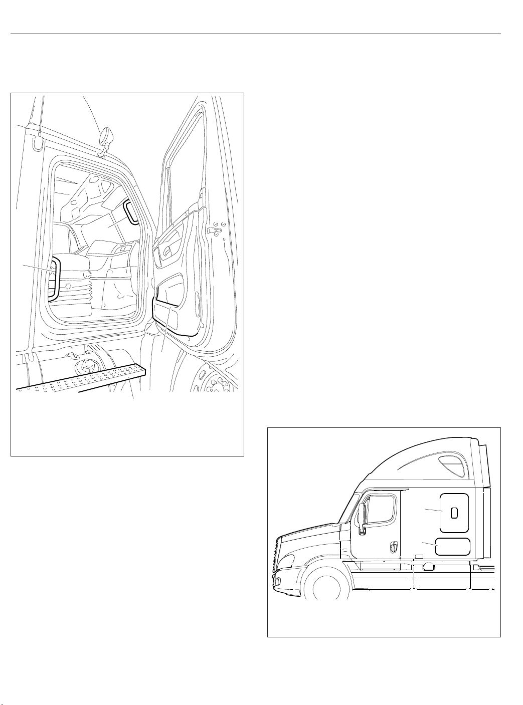
Grab Handles and Access
Steps
WARNING
Wet or dirty shoe soles greatly increase the
chance of slipping or falling. If your soles are wet
or dirty, be especially careful when climbing
onto, or down from, the back-of-cab area.
Always maintain three-point contact with the
back-of-cab access supports while entering and
exiting the back-of-cab area. Three-point contact
means both feet and one hand, or both hands
and one foot, on the grab handles, steps, and
deck plates. Other areas are not meant to support back-of-cab access, and grabbing or stepping in the wrong place could lead to a fall, and
personal injury.
Be careful not to get hands or feet tangled in
hoses or other back-of-cab equipment. Carelessness could cause a person to trip and fall, with
possible injury.
2.1
Page 13

Entering the Driver Side
When entering the cab from the driver side, use the
grab handle and access steps as follows:
1.
Open the driver side door, and place anything
that you are carrying in the cab.
2.
Using both hands, grasp the grab handle that is
on the B-pillar, or use your left hand on the integral door lower grab handle. See
up as far as is comfortable.
1
5
4
11/30/2006
1. Steering Wheel
2. B-Pillar Grab Handle
3. Bottom Step
3
4. Top Step
5. Integral Door Lower
Fig. 2.3. Reach
2
f602271
Grab Handle
Vehicle Access
5.
Grasp the steering wheel with your left hand, and
step up.
6.
Step into the cab with your right foot first, and
grasp the steering wheel with your right hand.
Exiting the Driver Side
Exit the cab from the driver side as follows:
IMPORTANT: Do not attempt to exit the cab
while carrying any items in your hands.
1.
Grasp the steering wheel with both hands, place
your left foot on the top step, then stand on the
threshold facing into the cab.
2.
Using your right hand, grasp the grab handle,
located on the B-pillar.
3.
Move your right foot to the bottom step.
4.
Move your left hand to the integral door lower
grab handle.
5.
Step to the ground with your left foot first.
Entering the Passenger Side
When entering the cab from the passenger side, use
the grab handles and access steps as follows:
1.
Open the passenger-side door, and place anything that you are carrying in the cab.
2.
Using your left hand, grasp the grab handle
that’s on the rear of the door opening. See
Fig. 2.4.
3.
Using your right hand, grasp the integral door
lower grab handle.
4.
Place your right foot on the bottom step, and
step up to the upper step with your left foot.
5.
Place your right foot on the top step, and step
up.
6.
Move your right hand to the upper grab handle
on the windshield post.
7.
Step into the cab with your left foot first.
Fig. 2.3, Driver-Side Steps and Grab Handle
3.
Place your right foot on the bottom step, and pull
yourself up. Move your left hand to the integral
door upper grab handle.
4.
Place your left foot on the top step.
Exiting the Passenger Side
Exit the cab from the passenger side as follows:
IMPORTANT: Do not attempt to exit the cab
while carrying any items in your hands.
2.2
Page 14
Vehicle Access
2
1
3
01/03/2007 f720643
1. Lower Grab Handle
2. Upper Grab Handle
3. Integral Door Lower Grab Handle
4. Top Step
4
Cab-to-Sleeper Access
To open the sleeper access on vehicles with vinyl
sleeper curtains, unzip the sleeper curtains. If desired, unsnap the curtains all the way around the
sides and top, and remove the curtains.
To open the sleeper access on vehicles with velour
sleeper curtains, unfasten the snaps at one side,
then push the curtain to the opposite side.
Sleeper Door
The sleeper door (
entry or exit. The door is intended only as a convenient means to stow or remove personal belongings
in and from the sleeper area. To open the sleeper
door from the inside, push down on the lever handle
located inside the sleeper compartment aft of the
door, or pull out on the upper lever located inside the
cab door opening; see
door from outside, open the cab door, then pull out
on the upper lever located inside the cab door opening. To close the door, pull on the strap attached to
the inside of the door, or push it closed from the outside, until it latches.
IMPORTANT: The sleeper doors are two-stage
latching. When closing the doors, ensure that
they are completely latched to prevent wind
noise and water intrusion.
Fig. 2.5, Ref. 1) is not intended for
Fig. 2.6. To open the sleeper
Fig. 2.4, Passenger-Side Steps and Grab Handles
1.
Using both hands, grasp the grab handle thats
on the windshield post, and place your right foot
on the top step while standing up from the seat
facing inward.
2.
Place your left foot on the bottom step.
3.
Move your left hand to the lower grab handle
located at the rear edge of the door opening.
Fig. 2.4.
See
4.
Move your right hand to the integral door lower
grab handle.
5.
Step to the ground with your right foot first.
2.3
04/20/2007
1. Sleeper Door
2. Luggage Compartment Door
Fig. 2.5, Sleeper Doors
1
2
f602302
Page 15

Vehicle Access
1
2
03/22/2007
1. Sleeper Door Lever
2. Luggage Door Lever
Fig. 2.6, Sleeper Door Levers
f720661
Sleeper Luggage Door
To open the sleeper luggage door, pull out on the
lower lever located inside the cab door opening. See
Fig. 2.6. To close the door, push it closed until it
latches.
Back-of-Cab Access
WARNING
External surfaces of the exhaust system remain
hot after the engine has been shut down. When
accessing the back of the cab or sleeper, do not
touch any part of the exhaust system, or severe
burns could occur.
When trailer air and electrical connections cannot be
reached conveniently from the ground, Federal Motor
Carrier Safety Regulations require commercial carriers to provide back-of-cab access.
Optional grab handles are mounted either on both
cab sidewalls, or on the left sidewall only. See
Fig. 2.7. Steps are mounted either on the fuel tank(s)
or on metal brackets. When a deck plate is necessary, it is mounted across the top of the frame rails.
IMPORTANT: Climb onto, and down from, backof-cab access facing in toward the vehicle, as
you would on a ladder. Do not climb up or down
facing out away from the vehicle.
2
3
1
1
09/24/2007
1. Steps
2. Grab Handle
Fig. 2.7, Back-of-Cab Access
3. Deck Plate
f602335
WARNING
Wet or dirty shoe soles greatly increase the
chance of slipping or falling. If your soles are wet
or dirty, be especially careful when climbing
onto, or leaving, the back-of-cab area.
Always maintain three-point contact with the
back-of-cab access supports while entering and
exiting the back-of-cab area. Three-point contact
means both feet and one hand, or both hands
and one foot, on the grab handles, steps, and
deck plates. Other areas are not meant to support back-of-cab access, and grabbing or stepping in the wrong place could lead to a fall, and
personal injury.
2.4
Page 16
Vehicle Access
Be careful not to get hands or feet tangled in
hoses or other back-of-cab equipment. Carelessness could cause a person to trip and fall, with
possible injury.
Entering Back-of-Cab
When climbing onto the deck plate, do the following:
1.
Grasp the sidewall grab handle with both hands.
Reach up as far as is comfortable.
2.
Place one foot on the bottom step and pull yourself up.
3.
Place your other foot on the top step.
4.
Move your lower hand to a higher position on the
grab handle.
5.
Step onto the deck plate.
Climbing Down from Back-of-Cab
To climb down from the back-of-cab area:
1.
Grasp the sidewall grab handle with both hands.
2.
Step one foot at a time onto the top step.
3.
Move your upper hand to a lower position on the
grab handle.
4.
Move one foot to the bottom step.
5.
Move your upper hand to a lower position on the
grab handle.
6.
Step to the ground with your upper foot first.
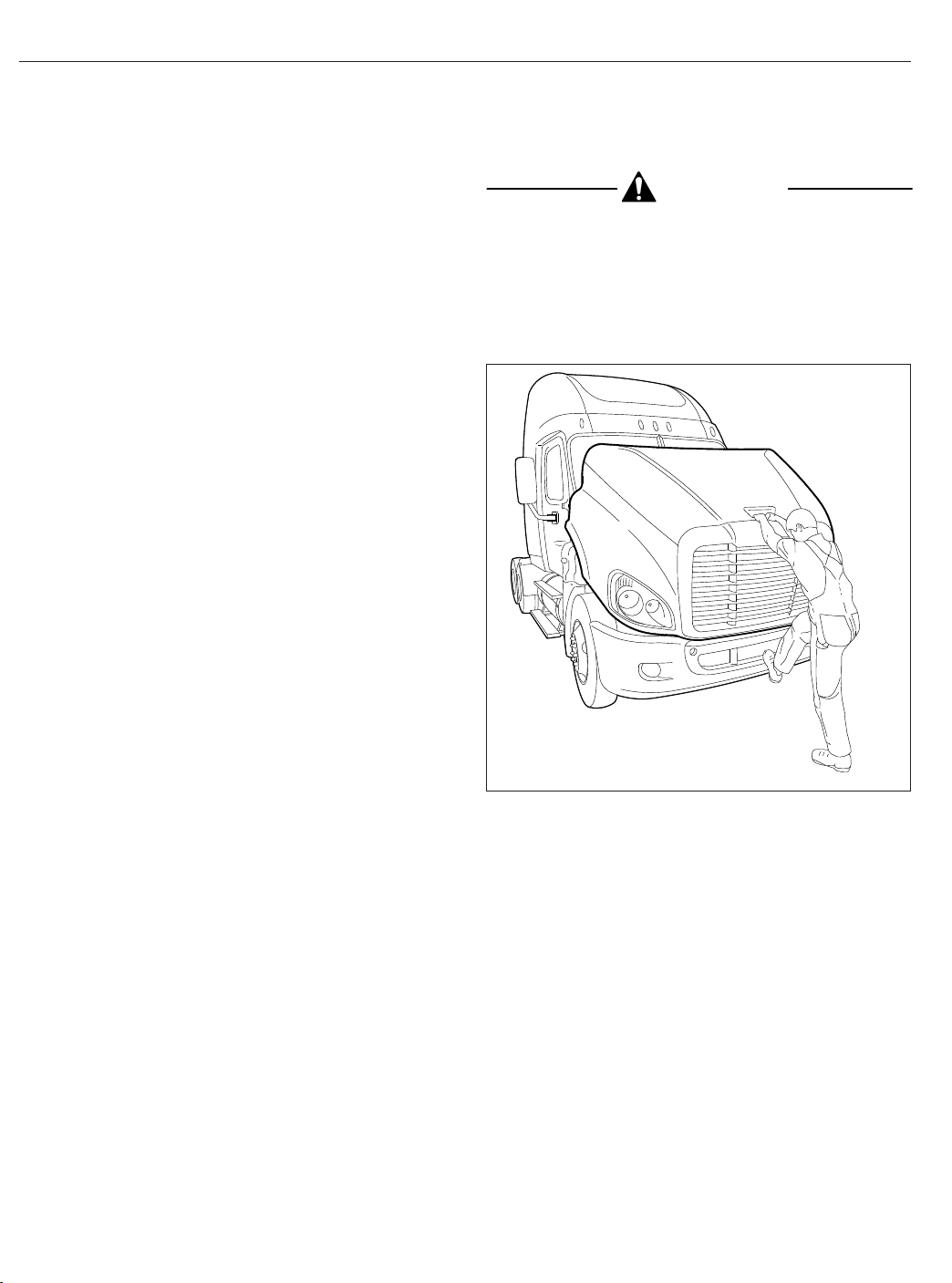
CAUTION
Do not let the hood free-fall to the full-open position. To do so could cause damage to the hood
or hood straps.
3.
Using the bumper step and grab handle, slowly
tilt the hood until the straps support it. See
Fig. 2.8.
03/22/2007
Fig. 2.8, Hood Tilting
f880788
Hood Opening and Closing
A grab handle at the front of the hood provides a
hand-hold for hood tilting. Two tilt-assist struts help to
tilt the hood open, and to return it to the operating
position. A damper controls the closing rate of the
hood and hood straps prevent the hood from overtravel. In the operating position, the hood is secured
by a hold-down latch on each side of the hood.
To Tilt the Hood
1.
Apply the parking brakes.
2.
Release both hood hold-down latches by pulling
the ends outward.
2.5
To Return the Hood
1.
Grasp the grab handle, and lift the hood a justover-center position.
2.
As the hood goes over center, the hood damper
controls the rate of descent to the operating position.
3.
Make sure the hood is flush with the cowl, then
secure the hood by engaging both hood holddown latches.
IMPORTANT: Make sure that both hold-down
latches are fully engaged before operating the
vehicle.
Page 17

3
Electrical System
Electrical Power Distribution ........................................................ 3.1
Emergency Power Supply .......................................................... 3.3
Progressive Low Voltage Disconnect ................................................. 3.4
Page 18

Electrical System
Electrical Power Distribution
Electrical power distribution provides battery power to
the electrical and electronic systems. See
power distribution component locations.
The following components make up the power distribution system:
•
MEGA Fuse Junction Block (MFJB), EPA07
only
•
Powertrain Power Distribution Module
(PT-PDM)
•
Powernet Distribution Box (PNDB), EPA10 and
newer
•
Cab Load Disconnect Switch
•
Auxiliary PDM
MEGA Fuse Junction Block, EPA07
On EPA07 vehicles, the MFJB distributes battery
power to the alternator, SAM cab, SAM chassis, and
powertrain PDM. Battery power may also be routed
to an inverter and a trailer PDM. The MFJB houses
up to five MEGA fuses, and is located on the left
frame rail in front of the batteries. See
Powernet Distribution Box, EPA10
and Newer
The PNDB distributes battery power to the SAM cab,
SAM chassis, powertrain PDM, and other keep-alive
circuits.
The PNDB is mounted in the engine compartment on
the frontwall near the steering column. The label on
the PNDB fuse cover identifies typical circuits. See
Fig. 3.3.
Power Distribution Modules
Powertrain PDM
The powertrain PDM contains fuses and relays that
provide battery and ignition power to the engine, aftertreatment device, transmission, and other
powertrain-related circuits. It is mounted in the engine compartment, above the driver-side inner
fender.
Fig. 3.1 for
Fig. 3.2.
Auxiliary PDM
The optional auxiliary PDM is used when additional
circuit protection is needed for optional features. For
example, if a beacon light is added to the Cascadia,
it may require an auxiliary PDM. The auxiliary PDM
may contain fuses and relays for these devices. It is
mounted in the cab, behind the doghouse cover.
Trailer PDM
The optional trailer PDM, mounted on the frame rail,
is used to supply trailer power to the chassismounted trailer receptacles. The SAM chassis supplies control signals to the relays in the trailer PDM.
SAM Cab
The SAM cab is located behind the glove box inside
the vehicle cab. See
fuses and relays in addition to solid state circuit protection devices that will trip when a circuit is overloaded.
Refer to
Chapter 25 for fuse and relay locations.
Fig. 3.4. The SAM cab contains
SAM Chassis
The SAM Chassis is located in the engine compartment on the driver-side frontwall. See
SAM chassis contains fuses and relays in addition to
solid state circuit protection devices that will trip
when a circuit is overloaded.
Refer to
Chapter 25 for fuse and relay locations.
Fig. 3.3. The
Circuit Protection Features
The SAM chassis and SAM cab may be equipped
with self-resetting circuit breakers instead of fuses.
Self-resetting circuit breakers are tripped when they
reach 170°F (77°C), then self-reset once the temperature drops sufficiently. When the circuit overload
is removed, this circuit protection will self-reset.
Some of these circuits require the ignition switch to
be cycled off then back on again for the self-reset to
occur.
Some ECU’s are equipped with a self-resetting circuit
breaker removal tool.
WARNING
3.1
Always wear heat-protective gloves when handling a self-resetting circuit breakers, which can
Page 19

Electrical System
1
2
02/27/2012
1. SAM Cab
2. Powertrain PDM (PT-PDM)
3. Powernet Distribution Box (PNDB)
4. SAM Chassis
5. Main Ground Junction Block
Fig. 3.1, Component Locations
reach extremely high temperatures. Failure to use
appropriate heat protection can lead to serious
injury.
NOTICE
Self-resetting circuit breakers can be permanently damaged if improperly handled. Use the
guidelines below to handle them safely.
•
Disconnect the batteries before removing a
self-resetting circuit breaker.
9
8
7
6
5
4
3
6. MEGA Fuse Junction Block
7. Cab Load Disconnect Switch (optional location)
8. Cab Load Disconnect Switch (optional location)
9. Trailer PDM
•
Use a circuit breaker removal tool to remove a
self-resetting circuit breaker. See
of any other tool, including pliers, may damage
the circuit breaker.
•
Never attempt to probe a self-resetting circuit
breaker while installed on the SAM Cab or
SAM Chassis. Remove the circuit breaker first,
or use a non-contact infrared thermometer to
measure temperature.
f001175a
Fig. 3.5. Use
3.2
Page 20

Electrical System
Cab Load Disconnect Switch
1
2
06/15/2007 f545073
1. MEGA Fuse Junction Block
2. Main Ground Junction Block
Fig. 3.2, EPA07 MEGA Fuse Junction Block
4
WARNING
Turning the cab load disconnect switch (CLDS) to
the off position does not disconnect the connection between the battery and the starter. To work
on the vehicle safely, the negative leads must be
disconnected from the battery.
IMPORTANT: The ignition should be turned off
before turning the CLDS to on or off.
The CLDS is used to avoid excessive draw on the
battery when the vehicle is parked for an extended
period of time by disconnecting (or opening) the connection between the battery and the most of the vehicle electrical system.
The CLDS may be mounted:
•
inside the cab on the outboard side of the
driver’s seat;
•
at the battery box;
•
outboard on the left frame rail.
Fig. 3.6 for an EPA07 CLDS; see Fig. 3.7 for an
See
EPA10 and newer switch.
If the CLDS is turned to the off position while the vehicle is running, the emergency power system will
activate. The powertrain PDM will receive power from
the emergency power feed, but the batteries will not
be charging. See the Emergency Power Supply
heading below for details.
3
2
02/27/2012 f545682a
1. Powertrain PDM (PT-PDM)
2. Inline Fuse, Auxiliary PDM
3. SAM Chassis
4. Powernet Distribution Box (PNDB)
Fig. 3.3, Engine Compartment Power Distribution
3.3
1
Components
Emergency Power Supply
The Cascadia electrical system has an emergency
power circuit that supplies battery power for exterior
lighting. This assists vehicle visibility in the event a
MEGA fuse is open circuit. The emergency power
circuit is live even when the CLDS is turned off.
The emergency power supply feature allows for the
vehicle to be driven off the highway and for the exterior lighting to remain on in the event of a SAM Cab
or SAM Chassis failure. The emergency power supply will cause certain exterior lamps to flash (depending on if it is the SAM Cab or SAM Chassis that
failed), indicating that the vehicle is disabled.
Page 21

Electrical System
f54494502/07/2007
Fig. 3.4, SAM Cab Location
SAM Cab Fault
If the emergency power supply system activates, do
not shut down the engine until the vehicle is in a safe
position to do so. It will not be able to be restarted
until the problem is corrected. If emergency power
mode is due to a SAM Cab fault, the gauges will become unresponsive but the engine will remain running until it is turned off.
When the ignition is in the ON position, the emergency power supply will cause the following lamps to
flash:
•
dash panel lights
•
clearance lights
•
front marker lights
•
side marker lights
•
trailer taillights
•
rear stop lights
SAM Chassis Fault
The engine may be able to be restarted when the
SAM Chassis fails. When the ignition is in the ON
position, the emergency power supply will cause the
following lamps to flash:
•
dash panel lights
•
identification lights
•
front marker lights
•
turn-signal indicators in the ICU (alternately)
•
side marker lights
•
rear turn-signal lights
•
trailer taillights
If the ignition switch is turned ON while the load disconnect switch is in the OFF position, the emergency
power supply feature will activate the following
lamps:
•
clearance lights (flashing)
•
side marker lamps (flashing)
•
low beam headlights
Progressive Low Voltage
Disconnect
The progressive low voltage disconnect (PLVD) feature protects the batteries from excessive discharge
by disconnecting certain circuits from battery power
supply. This allows the batteries to maintain acceptable charge to restart the vehicle.
When battery voltage drops below a predetermined
value, loads designated as comfort loads (priority
3.4
Page 22

Electrical System
1
06/19/2007 f545071
Fig. 3.6, Cab Load Disconnect Switch, EPA07
2
02/20/2012 f545876
1. Circuit Breaker
Removal Tool
Fig. 3.5, Self-Resetting Circuit Breaker Removal
2. Self-Resetting Circuit
Breaker
05/13/2009 f545527
Fig. 3.7, Cab Load Disconnect Switch, EPA10 and
Newer
level I) are shut down first. Then loads designated as
house loads (priority level II) are shut down. If necessary, basic loads (priority level III) are shut down last.
PLVD allows the driver to continue using critical
loads, while noncritical loads are temporarily unavailable. Calculations for disconnecting loads are based
on battery voltage, ignition switch status, and engine
rpm. Also, a time delay is implemented for the shutdown and reactivation of loads to avoid unnecessary
cycling of loads when battery voltage is close to
shutdown thresholds.
beeps. No alarm sounds before basic loads are shut
down.
If the interior lights have been shut down by PLVD,
pressing one of the interior light switches (if
equipped) brings the interior lights back on.
Table 3.1 for the type of loads shut down under
See
specific conditions.
Table 3.2 for the loads that are designated com-
See
fort, house, and basic load status.
One minute before the comfort loads or house loads
are shut down, the alarm in the instrument cluster
Type of Loads Shut Down Under Specific Conditions
Key Switch Position
Off N/A Priority level I, II loads Priority level I, II, and III loads
Accessory N/A Priority Level I loads Priority level I, II loads
Engine On, Voltage less than
12.5 Volts
Engine Off, Voltage less than
12.3 Volts
Engine Off, Voltage less than
12.1 Volts
3.5
Page 23

Key Switch Position
On Priority level I loads Priority Level I loads Priority level I, II loads
Start N/A N/A N/A
Priority Level I
Priority Level II
Electrical System
Type of Loads Shut Down Under Specific Conditions
Engine On, Voltage less than
12.5 Volts
Table 3.1, Type of Loads Shut Down Under Specific Conditions
Type of Load Function
Engine Off, Voltage less than
12.3 Volts
Designated Loads
12V power receptacle 6 (sleeper, refrigerator)
Amplifier power, accessory
General sleeper light
Foot well light
Reading light 1 (dimmer/theater)
Reading light 2 (dimmer/theater)
Rear baggage compartment light
12V power receptacle 5 (sleeper, cigar), battery
Auxiliary circulation fan-sleeper, battery
12V power receptacle 4 (sleeper, cigar), battery
Reading light 4 (switched locally), battery
Heated seats, ignition
*
Sleeper HVAC controller, accessory
Cabin HVAC controller, accessory
*
Radio, accessory (clamp 15R)
Power feed spare output I, battery
Power feed spare output III, battery
Mirror heating, passenger
Mirror heating, driver
*
*
Power feed spare output IV, battery
Power feed spare output II, battery
Fuel/water separator heater element, ignition
Air dryer (pneumatic, electrically heated), accessory
Auxiliary circulation fan-windshield, accessory
Accessory heater power
Utility light
Utility light
Dome light rear
Area lighting (lower bunk and sleeper work surface),
battery
Dome light cab, battery
Overhead compartment lights, battery
12V power receptacle 3 (sleeper, cigar), battery
Stand-alone HVAC, battery
Advertising light, accessory
*
Dome light passenger
Dome light driver/forward overhead
Engine Off, Voltage less than
12.1 Volts
*
*
*
*
3.6
Page 24

Electrical System
Type of Load Function
Priority Level III
*
When the vehicle has Optimized Idle, these functions will not operate with the ignition switch in the accessory
position. Optimized Idle may also turn these functions off to reduce stress on the batteries. Refer to the Optimized Idle section in
†
May or may not shut down depending on how an additional parameter is set at the factory or dealership.
Designated Loads
CB radio, battery
Fleet management system, battery
Trailer power, battery or ignition
12V power receptacle 2 (dash, phone), battery
12V power receptacle 1 (dash, cigar), battery
Chapter 11 for more information.
Table 3.2, Load Designation
†
†
3.7
Page 25

4
Instruments
Instrumentation Control Units ....................................................... 4.1
Warning and Indicator Lights ........................................................ 4.3
Instruments ...................................................................... 4.7
Driver Message Center ........................................................... 4.11
Overhead Instrument Panel ........................................................ 4.24
Page 26

Instruments
Instrumentation Control Units
•
"Driver Message Center"
The instrumentation control unit (ICU) provides the
driver with engine and vehicle information. It is comprised of standard and optional gauges, an audible
warning, a driver message center, and a lightbar containing warning and indicator lamps (also known as
telltales). Warning and indicator lamps illuminate in
red (danger), amber (caution), green (status advisory), or blue (high-beam headlights active).
Cascadia vehicles are equipped with an ICU3, ICU4,
ICU4M, or ICU4Me. See
Fig. 4.1, Fig. 4.2, and
Fig. 4.3 for typical ICU layouts.
The following headings in this chapter provide additional information and operating instructions for ICU
components:
•
"Warning and Indicator Lights"
•
"Instruments"
11
3
4
10
Ignition Sequence
When the ignition is turned on, the ICU runs a selfcheck. See
is a good way to ensure the ICU is functioning properly.
IMPORTANT: Do not crank the engine until the
ICU self-check is complete.
NOTE: Air gauges do not complete a sweep of
their dials during the ignition sequence.
When the ignition is turned on, the following actions
should occur:
•
Fig. 4.4. Observing the ignition sequence
electronic gauges complete a full sweep of
their dials
5
2
1
09/10/2009
1. Transmission Temperature Gauge
2. Coolant Temperature Gauge
3. Engine Oil Pressure Gauge
4. Driver Message Center
5. Fuel/DEF Level Gauge
4.1
9
6. Primary Air Pressure Gauge
7. Secondary Air Pressure Gauge
8. Speedometer
9. Tachometer
Fig. 4.1, ICU3 Instrument Cluster (EPA10 shown)
8
10. High Beam Indicator
11. Driver Display Screen
12. Mode/Reset Switch
13. Satellite Gauges
6
12
7
13
f610864a
Page 27

Instruments
1
34
5
09/10/2009
NOTE: The ICU4 and ICU4M are nearly identical, with the exception of the driver message center (Item 7).
1. Battery Voltage Gauge
2. Lightbar
3. Engine Oil Pressure Gauge
4. Coolant Temperature Gauge
5. Engine Oil Temperature Gauge
•
warning and indicator lamps illuminate, then
2
89
6
6. Turbo Boost Air Pressure Gauge
7. Driver Message Center
8. Tachometer
9. Speedometer
10. Primary Air Pressure Gauge
Fig. 4.2, ICU4M Instrument Cluster (EPA10 shown)
are extinguished
•
audible alert sounds for approximately four
seconds or until sufficient air pressure builds
up in the primary and secondary air systems
•
DEF level indicator illuminates all segments
green, then turns them off one at a time before
turning the leftmost segment amber and then
red
•
Freightliner logo displays on the ICU4Me driver
message center for two seconds.
•
software revision level of the ICU is displayed
on the driver message center, followed by any
active faults
IMPORTANT: If any red or amber warning and
indicator lamps do not illuminate during the ICU
self-check or do not go out after the self-check
completes, take the action outlined in
Table 4.1,
or take the vehicle to an authorized Freightliner
service facility as soon as possible.
7
10
11 12
13 14
11. Fuel/DEF Level Gauge
12. Secondary Air Pressure Gauge
13. Pyrometer
14. Rear Axle Temperature Gauge
NOTE: If active faults are present, take the vehicle to an authorized Freightliner service facility
as soon as possible.
If the ICU receives active fault codes, it displays
them one after the other until the parking brake is
released or the ignition is turned off. Once the parking brake is completely released, the ICU displays
the odometer. If there are no active faults, the ICU
displays the odometer after the self-check completes.
When the self-check is complete on an ICU4M, the
fasten seat belt screen displays if the engine is off. If
the engine is running, the idle hours screen displays.
Audible Alerts
An audible alert sounds during the ignition sequence
and whenever one of the following conditions exists:
•
Engine oil pressure falls below the minimum
preset value.
•
Coolant temperature rises above the maximum
preset value.
f610865b
4.2
Page 28

Instruments
10
1
2
4
5
6
3
06/27/2012 f611164
1. Engine Oil Temperature Gauge
2. Front Axle Temperature Gauge
3. Rear Axle Temperature Gauge
4. Speedometer and Coolant
5. Fuel/DEF Level Gauge
6. Tachometer and Engine Oil
Pressure Gauge
7. Primary Air Pressure Gauge
8. Secondary Air Pressure Gauge
9. Transmission Oil Temperature
Gauge
10. Driver Message Center
7
8
9
Temperature Gauge
Fig. 4.3, ICU4Me Instrument Cluster
•
IGNITION SWITCH
TURNED TO ON
Air pressure falls below approximately 70 psi
(483 kPa).
•
Parking brake is set with the vehicle moving
faster than two miles per hour.
•
System voltage falls below 11.9 volts.
ICU PERFORMS
SELF−TEST
IF NO FAULTS
WERE DETECTED
123456.7
MI
12.3 VOLTS
PARKING BRAKE
RELEASED
123456.7
MI
12.3 VOLTS
01/18/2012 f040420c
IF FAULT DETECTED
APU 190
PARKING BRAKE
RELEASED
Fig. 4.4, ICU Ignition Sequence
•
Door is open or the headlights are on, with the
parking brake off.
•
Driver seat belt is not fastened with the parking
brake off (optional).
•
Outside temperature falls below 35°F (1.7°C)
(optional).
Warning and Indicator Lights
The ICU lightbar has three or four rows of warning
and indicator lights with icon symbols, depending on
the ICU. The positions of the lights may vary for the
different ICU’s, but the telltales are standard for all
applications. See
and commonly used warning and indicator lamps.
Table 4.1 for a listing of standard
4.3
Page 29

Instruments
Warning and indicator lamps illuminate in red (danger), amber (caution), green (status advisory), or
blue (high-beam headlights active).
IMPORTANT: Depending upon local jurisdictional emissions guidelines, vehicles and/or en-
Common Warning and Indicator Lamps
Lamp Description Color
Indicates a serious fault that requires engine shutdown
immediately. The engine protection system will reduce the
maximum engine torque and speed, and, if the condition
does not improve, will shut down the engine within 30 to 60
seconds.
STOP
STOP Engine
High Coolant Temperature
Low Air Pressure (EPA07)
*
Safely bring the vehicle to a stop on the side of the road
and shut down the engine as soon as the red light is seen.
If the engine shuts down while the vehicle is in a
hazardous location, turn the key to the OFF position for
a few seconds, then restart the engine and move the
vehicle to a safer location.
Indicates the coolant temperature is above the maximum
allowable temperature.
Indicates air pressure in the primary or secondary reservoir
has dropped below approximately 70 psi (483 kPa).
gines that are domiciled outside of the U.S. and
Canada may not be compliant with EPA07,
EPA10, or GHG14 regulations. Noncompliant
vehicles may not be equipped with all of the
lamps shown in
Table 4.1.
Red
Red
Red
BRAKE
Low Air Pressure (EPA10
and Newer)
Low Engine Oil Pressure
Transmission Overheat Indicates high transmission temperature. Red
Transmission Fluid Level
Parking Brake (EPA07)
Parking Brake (EPA10
and Newer)
Low Battery Voltage Indicates that battery voltage is 11.9 volts or less. Red
Indicates air pressure in the primary or secondary reservoir
has dropped below approximately 70 psi (483 kPa).
Indicates the engine oil pressure is below the minimum
allowable pressure.
Indicates low transmission fluid level. Safely bring the
vehicle to a stop as soon as possible.
Indicates the parking brake is engaged, or hydraulic brake
fluid pressure is low. An audible alert activates when the
vehicle is moving over 2 mph (3 km/h) with the parking
brake set.
Indicates the parking brake is engaged. Red
Red
Red
Red
Red
4.4
Page 30

Instruments
Unfastened Seat Belt
Common Warning and Indicator Lamps
Lamp Description Color
Activates with an audible alert when the system detects that
the parking brake is off and the driver seat belt is not
fastened on some vehicles. On other vehicles, this lamp
illuminates for 15 seconds when the ignition is first turned
on.
Red
CHECK
Check ECAS
CHECK Engine
*
High Exhaust System
Temperature (HEST)
*
Diesel Particulate Filter
(DPF) Status
Malfunction Indicator
Lamp (MIL)
Vehicle ABS
Trailer ABS
Indicates Electronically Controlled Air Suspension (ECAS)
active fault.
Indicates an engine condition (low oil pressure, low coolant
level, high coolant temperature, high DPF soot level, or
uncontrolled DPF regeneration) that requires correction.
Correct the condition as soon as possible. If the condition
worsens, the STOP engine lamp will illuminate.
Slow (10-second) flashing indicates a regeneration (regen)
is in progress.
IMPORTANT: When the HEST lamp is illuminated, do
not park the vehicle near flammable material.
Solid illumination indicates high exhaust temperatures at the
outlet of the tail pipe when speed is below 5 mph (8 km/h).
Solid illumination indicates a regen is required. Change to a
more challenging duty cycle (such as highway driving ) to
raise exhaust temperatures for at least twenty minutes, or
perform a parked regen.
Blinking indicates that a parked regen is required
immediately. An engine derate and shutdown will occur.
Indicates an emissions-related fault. See the engine
operation manual for details.
Momentary illumination indicates the vehicle ABS is
engaged.
Solid illumination indicates a problem with the vehicle ABS.
Repair the ABS immediately to ensure full braking
capability.
Momentary illumination indicates the trailer ABS is engaged.
Solid illumination indicates a problem with the trailer ABS.
Repair the ABS immediately to ensure full braking
capability.
Red
Amber
Amber
Amber
Amber
Amber
Amber
4.5
NO
CHARGE
No Charge
Water in Fuel
Indicates the alternator is not properly powering the
electrical system.
Indicates the fuel may contain water. Drain any water
collected in the fuel/water separators.
Amber
Amber
Fuel Filter Restriction Indicates the fuel filter is clogged and requires service. Amber
Page 31

Instruments
Common Warning and Indicator Lamps
Lamp Description Color
IDLE
MGMT
WAIT
TO START
START
BLOCKED
WHEEL
SPIN
Optimized Idle Indicates optimized idle is enabled. Amber
Check Transmission Indicates an undesirable transmission condition. Amber
Indicates that the system is preventing the starter from
cranking. This can occur when the ignition switch is turned
Wait To Start (EPA07/
EPA10)
to START before the gauge sweep has completed, or if the
starter has overheated.
Amber
Turn the ignition switch back to ON, wait for the lamp to go
out, then turn the ignition switch to START again.
Indicates that the system is preventing the starter from
cranking. This can occur when the ignition switch is turned
to START before the gauge sweep has completed, or if the
starter has overheated.
Start Blocked (GHG14)
NOTE: Illumination of the Start Blocked lamp does not
Amber
indicate a problem with the starter.
Turn the ignition switch back to ON, wait for the lamp to go
out, then turn the ignition switch to START again.
Flashing indicates the ATC system is active, or the ATC
button has been pressed to allow wheel slip.
Wheel Spin
Solid illumination indicates a problem with the ATC system.
Amber
Repair the ATC system immediately to ensure full braking
capability.
Momentary illumination indicates that a stability event has
occurred.
Roll Stability
On vehicles that are also equipped with ATC, flashing
Amber
indicates the ATC button has been pressed to allow wheel
slip.
Hill Start Aid (HSA)
Override
Outside Normal Ride
Height
Indicates the HSA switch has been pressed to override the
hill start assist feature.
Indicates the current rear suspension height is not at the
normal ride height. This light will turn off once the vehicle
returns to normal ride height.
Amber
Amber
Engine Brake Indicates the engine brake is enabled. Green
Left-Turn Signal
Right-Turn Signal
Flashing indicates the outside left-turn signal lights are
activated.
Flashing indicates the outside right-turn signal lights are
activated.
Green
Green
4.6
Page 32

Instruments
Common Warning and Indicator Lamps
Lamp Description Color
Indicates the cruise control is enabled.
Cruise Control
High-Beam Headlights Indicates the high-beam headlights are on. Blue
*
See
Fig. 4.5 for an explanation of the aftertreatment system (ATS) warning indicators, and actions required to avoid further engine protection steps.
Table 4.1, Common Warning and Indicator Lamps
NOTE: The ICU4Me does not have a green cruise control
telltale.
Green
Engine Protection System
WARNING
When the red STOP engine lamp illuminates,
most engines are programmed to shut down automatically within 30 seconds. The driver must
immediately move the vehicle to a safe location
at the side of the road to prevent causing a hazardous situation that could cause bodily injury,
property damage, or severe damage to the engine.
See Fig. 4.5 for an explanation of the aftertreatment
system (ATS) warning indicators, and actions required to avoid further engine protection steps.
The STOP engine lamp illuminates when the engine
protection system is activated in one of two ways. On
some engines, the engine protection system will derate the engine, allowing it to run at lower rpm and
slower vehicle speed. Drive the vehicle to a safe location or to a service facility.
IMPORTANT: Safely bring the vehicle to a stop
on the side of the road and shut down the engine as soon as the red light is seen. If the engine shuts down while the vehicle is in a hazardous location, turn the key to the OFF position
for a few seconds, then restart the engine and
move the vehicle to a safer location.
On other engines, the engine protection system will
shut down the engine. It will first derate the engine,
then shut it down completely 30 to 60 seconds after
the indicator illuminates (depending on the critical
fault type) if the condition does not improve. Bring
the vehicle to a stop on the side of the road before
the engine shuts down.
Some vehicles may have a shutdown-override
switch, which may be used to momentarily override
the shutdown sequence. See
information regarding the shutdown process.
Chapter 11 for detailed
IMPORTANT: Do not attempt to restart the engine while the vehicle is moving. Bring the vehicle to a safe stop, then restart the engine.
To restart the engine, turn the ignition to OFF, leave
it there a few seconds, then turn the ignition to
START. The engine will run for a short period and
shut down again if the condition does not improve.
Instruments
Standard instruments are present on every vehicle.
They are listed here in alphabetical order to make
the information easier to find.
Optional instruments, typically located on the auxiliary dash panel or right-hand control panel, are not
found on every vehicle. They are listed here in alphabetical order, to make the information easier to find.
Air Intake Restriction Gauge
The air intake restriction gauge indicates the vacuum
on the engine side of the air cleaner. On standard
installations, it is mounted on the air intake duct in
the engine compartment. As an option for easier
viewing, the air intake restriction indicator (see
Fig. 4.6) can be mounted on the dash, usually on the
right-hand control panel.
NOTE: Rain or snow can wet the filter and
cause a temporary high reading.
Air intake restriction vacuum is measured in inches
of water (inH
graduated indicator or a restriction gauge on the
O). For vehicles equipped with a
2
4.7
Page 33

Instruments
EXHAUST AFTERTREATMENT SYSTEM INFORMATION
02/20/2009
INDICATOR
LAMP(S)
(Solid)
(Flashing) (Flashing)
CHECK
STOP
Level 1 Level 3Level 2 Level 4
Indicator Lamp
Message(s)
Diesel Particulate
Filter Condition
Required Action
For a driver performed Parked Regeneration, vehicle must be equipped with a dash mounted Regeneration Switch.
Filter Regeneration
Recommended.
Filter is reaching
capacity
.
Bring vehicle to
highway speeds to
allow for an
Automatic
Regeneration or
perform a Parked
Regeneration.
Filter
Regeneration
Necessary
Filter is now
reaching maximum
Switch.
capacity
.
To avoid engine
derate, bring vehicle
to highway speeds
to allow for an
Automatic
Regeneration, or
perform a Parked
Regeneration as
soon as possible.
Parked Regeneration
Required − Engine
Derate
Filter has reached
maximum capacity
Vehicle must be
parked, and a Parked
Regeneration must
be performed.
Engine will begin
derate.
Service Regeneration Required.
Engine Derate To Idle Only.
Filter has exceeded maximum
.
capacity.
Vehicle must be parked, and a
Service Regeneration must be
performed. Check engine
operator’s manual for details.
Engine will shut down.
Fig. 4.5, ATS Warning Lamps
Vehicles may be equipped with a go/no-go restriction
indicator without graduations (see
a graduated indicator.
Air Intake Maximum Restriction Values (inH2O)
Engine Make
Cummins 25 25
Detroit 20 22
Mercedes-Benz 22 22
Table 4.2, Air Intake Maximum Restriction Values
Pre-EPA07
Engines
W
ARNING
HEST (High Exhaust
System Temperature)
Flashing
A regeneration is in
progress.
Solid
Exhaust components
and exhaust gas are at
high temperature. When
stationary, keep away
from people and
flammable materials or
vapors.
Fig. 4.7) instead of
EPA07 and
Newer Engines
f080156
10/10/2001
f610568
Fig. 4.6, Air Intake Restriction Indicator
dash, check the gauge with the engine off. If the yellow signal stays locked in the red zone once the engine is shut down, or is at or above the values
shown in
Table 4.2, the air cleaner element needs to
be replaced.
Application Air Pressure Gauge
An application air pressure gauge registers the air
pressure being used to apply the brakes, and should
be used for reference only. The gauge will not register air pressure until the foot brake pedal is depressed or the trailer hand brake is applied.
4.8
Page 34

Instruments
04/08/2005
Fig. 4.7, Manual-Reset Air Restriction Indicator, Go/
No-Go
Coolant Temperature Gauge
NOTICE
A sudden increase in coolant temperature may
indicate engine or cooling system failure. Bring
the vehicle to a safe stop and investigate the
cause to prevent further damage. Do not operate
the engine until the cause has been determined
and corrected.
During normal engine operation, the coolant temperature gauge should read 175 to 195°F (79 to
91°C). If the temperature remains below 160°F
(71°C), inspect the cooling system to determine the
cause.
If coolant temperature rises above the maximum
temperature listed in
lamp will illuminate. If the condition does not improve, the STOP engine lamp will also illuminate and
an audible warning will sound. The engine will then
derate or shut down, depending on the type of engine protection system installed.
Maximum Coolant Temperature
Engine Make Temperature: °F (°C)
Cummins 225 (107)
Detroit 215 (101)
Mercedes-Benz 221 (105)
Table 4.3, Maximum Coolant Temperature
Table 4.3, the CHECK engine
f090431
Drive Axle Oil Temperature Gauges
NOTICE
A sudden increase in oil temperature that is not
caused by a load increase may indicate mechanical failure. Bring the vehicle to a safe stop and
investigate the cause to prevent further damage.
Do not operate the vehicle until the cause has
been determined and corrected.
During normal operation, drive axle oil temperature
gauges should read as follows:
•
160 to 220°F (71 to 104°C) for Detroit™and
Meritor™drive axles
•
180 to 200°F (82 to 93°C) for Dana Spicer®
drive axles
Under heavy loads, such as when climbing steep
grades, temperatures that exceed the normal oil temperature range for a short period are not unusual. If
the temperature returns to normal when the load decreases, there is no problem.
Engine Oil Pressure Gauge
NOTICE
A sudden decrease or absence of oil pressure
may indicate mechanical failure. Bring the vehicle
to a safe stop and investigate the cause to prevent further damage. Do not operate the engine
until the cause has been determined and corrected.
The engine oil pressure gauge displays the current
engine oil pressure. If engine oil pressure falls below
the minimum levels shown in
engine lamp will illuminate. If the condition does not
improve, the STOP engine lamp will also illuminate
and an audible warning will sound. The engine will
then derate or shut down, depending on the type of
engine protection system installed.
Minimum Oil Pressure
Engine Model
Cummins 15 (103) 35 (241)
Detroit 14 (97) 55 (350)
At Idle Speed:
psi (kPa)
Table 4.4, the CHECK
*
At Rated RPM:
psi (kPa)
4.9
Page 35

Instruments
Minimum Oil Pressure
Engine Model
Mercedes-Benz 7 (50) 36 (250)
*
Oil pressures are given with the engine at operating temperature. With
the engine cold, oil pressure may be higher. Individual engines may vary
from the listed pressures; observe and record pressures when the engine
is new to create a guide for checking engine condition.
Table 4.4, Minimum Engine Oil Pressure
At Idle Speed:
psi (kPa)
*
At Rated RPM:
psi (kPa)
Engine Oil Temperature Gauge
NOTICE
A sudden increase in oil temperature that is not
caused by a load increase may indicate mechanical failure. Bring the vehicle to a safe stop and
investigate the cause to prevent further damage.
Do not operate the engine until the cause has
been determined and corrected.
During normal operation, the optional engine oil temperature gauge should read:
•
200 to 260°F (93 to 126°C) for Detroit and
Cummins engines
•
177 to 203°F (81 to 95°C) for Mercedes-Benz
engines
Under heavy loads, such as when climbing steep
grades, temperatures that exceed the normal oil temperature range for a short period are not unusual. If
the temperature returns to normal when the load decreases, there is no problem.
Fuel Gauge, Pre-EPA10
The fuel gauge indicates the level of fuel in the fuel
tank(s). A single fuel gauge is standard. If equipped
with an optional second fuel tank, each fuel tank
level is indicated on a separate gauge.
Fuel/Diesel Exhaust Fluid (DEF)
Gauge, EPA10 and Newer
For engines that are EPA10-compliant or newer, the
fuel and DEF levels are measured in a dual purpose
fuel/DEF level gauge. See
The diesel fuel level is indicated at the top of the
gauge, with a low-fuel warning lamp that illuminates
amber when the diesel fuel level registers 1/8th of
capacity.
Fig. 4.8.
1
1/2
ULTRA LOW SULFUR
DIESEL FUEL ONLY
4
FE
DEF
EF
3
08/21/2009
1. Diesel Fuel Level Indicator
2. DEF Level Indicator
3. Low DEF Warning Lamp (amber below 10% DEF)
4. Low Fuel Warning Lamp (amber at 1/8 tank of fuel)
Fig. 4.8, Fuel/DEF Gauge, EPA10 and Newer
2
f611045
The DEF level is indicated in the lightbar on the
lower portion of the gauge. There is a low DEF level
warning lamp that illuminates amber when the DEF
level reaches 10% of capacity. See Chapter 12 for
details of the DEF gauge functions.
Primary and Secondary Air Pressure
Gauges
WARNING
If air pressure falls below minimum pressure, the
braking ability of the vehicle will be limited. Slow
the vehicle down and bring it to a gradual stop.
Do not attempt to move the vehicle until air pressure has risen above the minimum level. Moving
a vehicle without adequate braking power could
cause an accident resulting in property damage,
personal injury, or death.
Air pressure gauges register the pressure in the primary and secondary air systems. Normal pressure,
with the engine running, is 100 to 120 psi (689 to
827 kPa) in both systems.
A low-air-pressure warning light and audible alert,
connected to both the primary and secondary systems, activate when air pressure in either system
drops below approximately 70 psi (483 kPa).
4.10
Page 36

Instruments
When the engine is started, the warning light and
audible warning remain on until air pressure in both
systems exceeds minimum pressure.
Speedometer
Two speedometer options are available. The U.S.
version of the speedometer registers speed in both
miles per hour (mph) and kilometers per hour (km/h),
with mph in larger numbers. The metric version of
the speedometer face reverses this arrangement,
with km/h in larger numbers.
Tachometer
The tachometer indicates engine speed in revolutions
per minute (rpm) and serves as a guide for shifting
the transmission and keeping the engine in the appropriate rpm range. For low idle and rated rpm, see
the engine identification plate.
Transmission Fluid Temperature
Gauge
The transmission fluid temperature gauge indicates
the transmission lubricant operating temperature.
Temperatures vary by application, but the transmission fluid temperature gauge reading should not exceed 250°F (121°C).
Voltmeter
The voltmeter indicates the vehicle charging system
voltage when the engine is running and the battery
voltage when the engine is off. By monitoring the
voltmeter, the driver can stay aware of potential battery charging problems and have them fixed before
the batteries discharge enough to create starting difficulties. Cascadia vehicles are equipped with either a
voltmeter gauge, or a digital voltmeter readout located on the bottom line of the dash message center.
The voltmeter will normally show approximately 13.7
to 14.1 volts when the engine is running. The voltage
of a fully charged battery is 12.7 to 12.8 volts when
the engine is off. Battery voltage under 12.0 volts is
considered a low battery, and a completely discharged battery will produce only about 11.0 volts.
If the voltmeter shows an undercharged or overcharged condition for an extended period, have the
charging system and batteries checked at an authorized Freightliner service facility.
On a vehicle equipped with a battery isolator system,
the voltmeter measures the average voltage of all the
batteries when the engine is running. When the engine is off, the voltmeter shows only the isolated battery voltage and does not indicate the voltage of the
engine-starting batteries.
NOTICE
A sudden increase in transmission fluid temperature that is not caused by a load increase may
indicate mechanical failure. Bring the vehicle to a
safe stop and investigate the cause to prevent
further damage. Do not operate the vehicle until
the cause has been determined and corrected.
Under heavy loads, such as when climbing steep
grades, temperatures that exceed the normal oil temperature range for a short period are not unusual. If
the temperature returns to normal when the load decreases, there is no problem.
Turbocharger Boost Pressure Gauge
A turbocharger boost pressure gauge indicates the
pressure in the intake manifold, in excess of atmospheric pressure, being created by the turbocharger.
4.11
Driver Message Center
ICU3/ICU4
The driver message center is controlled using the
mode/reset switch, located on the right side of the
ICU, and the + and – buttons mounted in the righthand pod of the steering wheel (
Fig. 4.1 and Fig. 4.9. Tap the mode/reset switch or
the + switch to advance one screen; press and hold
either switch to select a menu choice or reset the
display. When the display resets, an audible chirp
sounds.
Four driving screens are accessible when the parking
brake is off. All screens and menus are accessible
when the parking brake is on (parked screens).
Driving Screens
The following screens are available when the parking
brake is off (when the vehicle is mobile) and no active fault codes are found. Use the + and – switches
on the steering wheel, or the mode/reset switch, to
Fig. 4.9). See
Page 37

+
MRKR
INT
−
ENG
BRK
02/06/2007
NOTE: To reset values in the ICU4M and ICU4Me driver
message centers, press and hold the + switch.
Fig. 4.9, Steering Wheel-Mounted Switches
f462061
scroll through the screens. To reset any values,
press and hold the + switch or the mode/reset
switch. The driving screens appear in the following
order:
i.
Odometer
ii.
Trip distance
iii.
Trip hours
iv.
Outside temperature
Parked Screens/Menus
The following screens and menus are available when
the parking brake is on (when the vehicle is parked)
and no active fault codes are found. Use the + and –
switches on the steering wheel, or the mode/reset
switch, to scroll through the driving screens. To reset
any values, press and hold the + switch or the mode/
reset switch. See
pear in the following order:
i.
Odometer
ii.
Trip distance
iii.
Trip hours
iv.
Outside temperature
v.
Temperature alert
vi.
Diagnostics
Fig. 4.10. The parked screens ap-
Instruments
vii.
Clear screen (on vehicles with less than 255
miles on the odometer)
viii.
Engine miles/hours
ix.
Setup
Temperature Alert
When the outside temperature drops to 35°F (1.7°C)
or less, the ICU displays a caution text at onesecond intervals for five seconds, and an audible
alert sounds. Tap the + or – switch on the steering
wheel, or the mode/reset switch, to acknowledge the
message. The audible alert will not sound again unless the temperature cycles above 37°F (4°C) and
back to 35°F (1.7°C) or less. This warning only occurs while the ignition is on and the parking brake is
released.
The temperature alert message allows the driver to
enable or disable the ambient temperature warning.
Press and hold the mode/reset switch to toggle between on and off. Release the mode/reset switch,
then tap it to select the displayed choice.
Diagnostics
When the DIAG screen is displayed, press and hold
the mode/reset switch to access the various diagnostic screens. See
nostic screens.
The diagnostic screens are used by trained technicians to retrieve fault codes and other diagnostic information pertaining to the vehicle. If active fault
codes display during start-up or at any other time,
make a note of the fault code and take the vehicle to
an authorized Freightliner service facility
If fault codes are displayed, press and hold the
mode/reset switch to view the next fault code until
reaching the DIAG screen.
Engine Miles/Hours
When the engine miles/hours screen is displayed,
press and hold the mode/reset switch to access the
engines screen submenu. See Fig. 4.11 for a diagram of the engine screens.
Fig. 4.11 for a diagram of the diag-
4.12
Page 38

Instruments
123456.7
MI
12.3 VOLTS
Tap
123456.7
TRIP MI
12.3 VOLTS
Tap
123456.7
TRIP HOURS
12.3 VOLTS
Tap
56°F
12.3 VOLTS
Tap
°t
n
01/30/2012 f040754
ALrt
Tap
Odometer
Press & Hold
To reset trip miles
Press & Hold
To reset trip hours
Press & Hold
To toggle ON
OFF
n
*Lo
**MI **HOURS
**no
dIAG
MI HOURS
Tap
123456.7
Tap
oiL
Tap
SEtUP
Tap
HOURS
ENGINE
ENGINE
Display diagnostics
Press & Hold
n = Number of Active Fault Codes
MI = Miles Interval Mode
HOURS = Hours Interval Mode
To display total
engine miles/hours
*Lo = Oil Level Low
HI = Oil Level High
Blank = Oil Level OK
− − = No Message
Press & Hold
**MI = Miles Interval Mode
**HOURS = Hours Interval Mode
**no = Service Interval Inactive
Display service
interval screens
Note: The engine oil level screen displays for Mercedes-Benz engines only (if equipped and enabled).
Fig. 4.10, ICU3 Parked Screens
Setup
The setup menu allows the driver to manage ICU
parameters. The setup screen submenu allows the
driver to enable and change service intervals. See
Fig. 4.12.
If service intervals are enabled and service distance
or time has been exceeded, the text SERVICE
HOUR/MI (KM) will display at start-up to indicate vehicle service is required.
For each parameter, press and hold the mode/reset
switch to navigate to the parameter change screen.
In each change screen, tap the mode/reset switch to
toggle between options.
Use the last screen in the setup menu, RESET EE,
to reset the parameters the ICU learns back to the
default settings. Press and hold the mode/reset
switch to reset the following learned parameters:
•
automated transmission display
•
seat belt switch learning
•
engine oil level
•
other electronic devices that have been removed from the vehicle (e.g. Qualcomm)
ICU4M
Functions
ICU4M settings and the driver message center are
controlled with the + and – switches and the MY
INFO switch, mounted on the dash. See
Tap the MY INFO switch to drill down from each
main screen to the submenus contained within it.
Use the + and – switches to scroll through screens
and select options. Tap the MY INFO switch again to
exit each change screen.
With the parking brake off, only the odometer and
alert messages can be displayed. Park the vehicle
and set the parking brake to access the parked
screens and menus.
Fig. 4.13.
4.13
Page 39

From Temp Alert Screen
Instruments
n = Number of
Active Fault Codes
dlAG
n
Tap
To Setup Screen (or Oil
Level Screen, if equipped)
Press & Hold
*If fault goes inactive,
display "noFault 1"
*FAULT
Press & Hold
01
Tap
AbS 11 ECU 0
Tap Tap
123456
SPN SPN
Tap Tap
FAIL 03 FAIL 00
*If fault goes inactive,
display "noFault n"
nn
*FAULT
Press & Hold
Tap
Press & Hold
123456
Press & Hold
Press & Hold
Tap Tap
01/31/2012
Fig. 4.11, ICU4 Diagnostic Screens
Alert Messages
The driver message center displays alert messages
when certain conditions occur. They are warnings,
cautions, or other messages that require the driver’s
attention, but not all of them are critical to the operation of the vehicle.
NOTE: If there is more than one alert message
to display, tap the + switch or the MY INFO
switch to access the next message, and so on,
until all messages have been viewed.
More important messages take priority over less important messages. The order of priority is:
1.
parking brake set (with the vehicle moving)
2.
parking brake off (with the door open)
3.
low oil pressure or high coolant temperature
4.
hard brake warnings (if equipped with roll stability advisor)
5.
low battery voltage
6.
ambient temperature below 35°F (1.7°C)
7.
turn signal on
8.
incoming instant or Qualcomm messages
9.
service warnings
f040802
4.14
Page 40

Instruments
From Engine
Miles/Hours Screen
SET UP SELECT
Press & Hold
*MI
Press & Hold
To toggle
MI
TapTap
WARN°T
Press & Hold
*on
Tap
To toggle
ON
OFF
LCD LMP
*on
Tap
Press & Hold to reset all
Service Interval counters
SET UP
**MI **HOURS
**no
Press & Hold Press & Hold
SERVICE SERVICE SERVICE
RESET
**MI **HOURS
*no
Tap Tap Tap
*12345
MI
MI
SERVICE
Selection?
no
Select NO
to disable
Service Intervals
KM
*no
HRS
To toggle
ON OFF
Press & Hold
SELECT
*MI *HOURS
TapTap
*12345
HOURS
SERVICE
Press & Hold
To toggle
MI
HOURS
no
Press & HoldPress & Hold
To Odometer
10.
no datalink activity
4.15
RESET
EE
Tap
Press & Hold
DONE
Tap
Fig. 4.12, ICU4 Setup Screens
Incoming Message
On vehicles with a Qualcomm onboard communications system, a notification appears on the driver
message center whenever a message is received.
NOTE:
* Flash screen text
**Display active mode
f04075501/30/2012
Page 41

02/22/2007
MY
INFO
Fig. 4.13, MY INFO Switch
f610887a
Instruments
High Coolant Temp
This message and an audible warning come on
whenever the engine coolant temperature exceeds
the maximum allowable temperature.
If high coolant temperature is detected during the
ignition sequence, it displays as an active fault instead of an alert message. After 30 seconds, the
message displays again.
Low Voltage
On some vehicles, this optional message and an audible warning come on whenever a low voltage condition is detected.
NOTE: The incoming message screen also displays during the ignition sequence if a message
is available.
This message displays for a preset time period, then
returns after a preset interval until it is dismissed by
the + and – switches or the MY INFO switch.
Parking Brake On
This warning message and an audible warning come
on whenever the parking brake is applied and the
vehicle is moving faster than 2 mph (3 km/h). See
Fig. 4.14. The screen and audible warning go away
only when the parking brake is released, or speed is
reduced below 2 mph.
WARNING
PARK BRAKE ON
06/21/2007
Fig. 4.14, Parking Brake On Alert Message
Low Oil Pressure
This warning message and an audible warning come
on whenever the oil pressure falls below the minimum oil pressure, whether the vehicle is idling or in
motion. Tap the + and – switches or the MY INFO
switch to dismiss the message.
If low oil pressure is detected during the ignition sequence, it displays as an active fault instead of an
alert message. After 30 seconds, the message displays again.
f601414
Turn Signal On
This warning message and audible warning come on
whenever the turn signal remains on for four minutes
or five miles of travel. To dismiss this message, either turn off the turn signal or tap the + and –
switches or the MY INFO switch.
Air Temperature
When the outside air temperature drops below 35°F
(1.7°C), a warning text is displayed at one-second
intervals for five seconds, and an audible warning will
sound. Tap the + and – switches or the MY INFO
switch to acknowledge the warning. The alert message will not occur again unless the temperature
cycles above 37°F (4°C) and back below 35°F
(1.7°C). This warning only occurs while the ignition is
on and the parking brake is off.
Service Warnings
Service warning alerts display during the ignition sequence and indicate if a service interval has been
reached or exceeded and maintenance is required.
The messages may indicate the number of miles
(KM) or hours until the next required service or, once
passed, the number of miles (KM) or hours since
maintenance should have been performed.
Automated Transmission Display
The ICU4M can display current gear information for
vehicles with an automated transmission. The last
three digits at the far right on the lower line of the
driver message center are reserved for this information.
4.16
Page 42

Instruments
When a shift request is made by the driver, an up or
down arrow is also displayed, depending on the shift
direction.
For more information about specific models of automated transmissions, see Chapter 15.
Driving Screens
The following screens are available when the parking
brake is off (when the vehicle is mobile).
Tap the MY INFO switch to drill down from each
main screen to the submenus contained within it.
Use the + and – switches to scroll through screens
and select options. Tap the MY INFO switch again to
exit each change screen. See
i.
Fasten seat belt (rpm<100)
ii.
Fuel economy (rpm>100)
+
R
=Holdtoreset.
C
onfir
mationscr
eenwilldispla
KEY
y
R
right afterthe firsthold.
PUSH+
TOCONFIRMCLEA
My Info
01/30/2012 f545600a
Fig. 4.15, ICU4M Driving Screens
Fig. 4.15.
Odometer
−0%III +
10.5 MPG 23456.7 MI
+
TRIP MILES 123456.7
TRIP HR 1234:56
+
TRIP ADVISORIES
123 ROLL 456 BRK
+
LEG MILES 123456.7
LEG HR 1234:56
+
LEG ADVISORIES
123 ROLL 456 BRK
+
FUEL USED 12345.6
AVG MPG 12:34
+
OUTSIDE AIR
TEMPERATURE 56F
−
−
−
−
R
R
−
R
R
−
R
iii.
Odometer
iv.
Trip distance/hours
v.
Trip advisory
vi.
Leg distance/hours
vii.
Leg advisory
viii.
Fuel used/average MPG (KM/L)
ix.
Outside air temperature
Favorite Screen
The driver can set a favorite driving screen using the
MY INFO switch. Press and hold the lower half of the
MY INFO switch for just over one second to set the
current screen as the favorite screen. A chirp will
sound to verify the screen has been set.
Tap the lower half of the MY INFO switch to access
the favorite screen. Tap the MY INFO switch again to
leave the favorite screen.
NOTE: Only driving screens can be set as the
favorite screen.
Parked Screens/Menus
Tap the MY INFO switch to drill down from each
main screen to the submenus contained within it.
Use the + and – switches to scroll through screens
and select options. Tap the MY INFO switch again to
exit each change screen. Press and hold the +
switch or the upper half of the MY INFO switch to
reset the counters for trip and fuel information.
The following screens are available when the parking
brake is on (when the vehicle is parked). See
Fig. 4.16.
i.
Odometer
ii.
Trip information including trip miles/hours, idle
hours, average speed, leg miles/hours
iii.
Fuel information including fuel used, fuel
economy, idle/PTO fuel usage
iv.
Engine information including engine miles/hours,
engine/PTO gallons, oil level
v.
Diagnostic information
vi.
Service information including mileage or time to
next service
vii.
Setup information
4.17
Page 43

viii.
Vehicle information including Datalink status, ICU
serial number, software version
Instruments
Diagnostic Information
01/30/2012
Odometer
IDLE HOURS 1234:56
12.3 GAL 123456.7 MI
TRIP MILES 123456.7
TRIP HR 1234:56
−
RR
TRIP ADVISORIES
123 ROLL 456 BRK
IDLE HOURS 1234:56
AVG MPH 12.3
− −
R
−
+
TRIP
INFORMATION
+
FUEL
INFORMATION
R
LEG MILES 123456.7
LEG HR 1234:56
−
−
−
FUEL USED 12345.6
AVG MPG 12:34
−
RR
LEG ADVISORIES
123 ROLL 456 BRK
IDLE GALLONS 12345.6
PTO GAL 12345.6
−
R
+
R
−
=Holdtoreset.
C
onfir
mationscr
right afterthe firsthold.
PUSH+
KEY
TOCONFIRMCLEA
My Info
eenwilldispla
y
R
+
ENGINE
INFORMATION
−
ENG MILES 1234567.8
ENG HOUR 1234:56
ENG GALLONS 123456.7
PTO GAL 123456.7
− − −
85
*Lo ENGINE
PER
OIL LVL
*Lo
ENGINE
−
To Diagnostic Information Screen
Fig. 4.16, ICU4M Idle Hours, Trip Information, Fuel Information, and Engine Information Screens
f545600b
ix.
Outside air temperature
x.
Fasten seat belt warning
Trip Information
Trip Information displays the trip miles, trip advisories, idle hours, leg miles, and leg advisories, in that
order.
Fuel Information
Fuel information displays total fuel usage since the
last reset, fuel mileage, and fuel consumed while
idling or running the PTO, in that order.
Engine Information
Engine information displays engine mileage and
hours, and total fuel consumption, in that order.
If active fault codes are displayed on the diagnostic
information screens, make a note of the fault code
and text message, then take the vehicle to an authorized Freightliner service facility See
Fig. 4.17 for a
diagram of the diagnostic information screens.
Service Information
The Service Information menu displays the next service interval, expressed in either miles or hours. See
Fig. 4.17. Service intervals can also be deactivated.
For programming service intervals, see Setup Information, below.
NOTE: If the vehicle has exceeded the service
interval, the miles(km)/hours remaining screen
is replaced by the service was due screen, followed by the number of miles(km)/hours since
the service was due.
4.18
Page 44
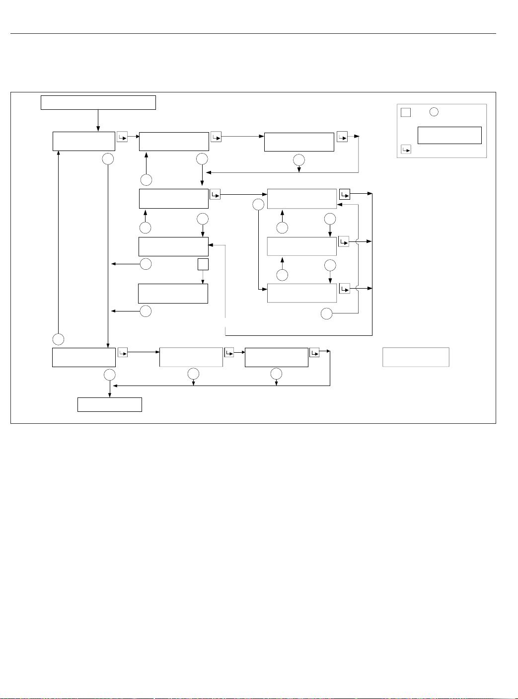
Instruments
From Engine Information Screen
DIAGNOSTI
INFORMATION
C
2HISTDASHFAULT
LASTCLR123456.7
+
−
−
This will also clear other vehicle ECU’s inactive
faults when od ometer is<254MI.
+
SERVIC
INFORMATION
E
−
ACTIVEFAULTS
3
+
HOLD+TO CLEAR
DASH FAULTS
ALLFAULT
CLEARE
2SecTimeout
12345
NEXTSERVICE
S
D
MILESTO
+
R
=Holdtoreset.
C
onfir
mationscr
eenwilldispla
KEY
y
R
right afterthe firsthold.
SA(text
)SA##SPN####
SPN(text)FMI
−−
S
+
SA(text
SPN(text)FMI
##
−
)SA#SPN#
#
PUSH+
TOCONFIRMCLEA
My Info
−−
+
LAST OCCUR 123456.7
1234 TI
M
ES
R
−
+
FIRST OCCUR 123456.7
1234 TI
M
ES
−
INTER
T
O
VALISSE
12345
MILES
T
If overdue:
SERVICEWASDU
MILES AGO
12345
E
−−
To Setup Screen
Fig. 4.17, ICU4M Diagnostic Information and Service Information Screens
Setup Information
The Setup Information menu allows the driver to program various features of the ICU4M. See
The setup features include:
1.
Service intervals (OFF/MILES/HOURS)
2.
Outside temperature warning (ON/OFF)
3.
Target MPG
4.
LCD lamp (ON/OFF)
5.
Driver message center brightness
6.
Language (English/French/Spanish)
7.
Units of measurement (English/Metric)
8.
Driver select (ON/OFF)
9.
Reset parameters to original settings
4.19
Fig. 4.18.
f54560101/30/2012
Vehicle Information Screens
The vehicle information screens display hardware
and software information, including the Freightliner
part number and switch ID of the ICU. See
Fig. 4.19.
ICU4Me
Functions
ICU4Me settings and the driver message center are
controlled using the ICU4Me control switch located
on the dash, and the + and – switches mounted in
the right-hand pod of the steering wheel. See
Fig. 4.20 and Fig. 4.9.
The driver message center is divided into four sections. The odometer and cruise control status field
are displayed along the bottom of the message center. When cruise control is active, the cruise control
Page 45

SETUP
INFORMATION
−
PUSH KEY TO
CHANGE SERVICE
+
PUSH KEY TO
CHANGE TEMP WARN
+
PUSH KEY TO
CHANGE TARGET MPG
+
PUSH KEY TO
CHANGE LCD LAMP
Instruments
Press to toggle between selections
SERVICE INTERVAL
OFF/*MILES/HOURS
−
TEMPERATURE WARNING
− OFF * ON +
−
TARGET MPG *8.5
− LESS MORE +
−
LCD LAMP
− OFF * ON +
−
+
−
Miles or Hours
Off
Press to toggle On Off
+
−
Press to increase target MPG
+
Press to decrease target MPG
−
Press to toggle On Off
+
−
PUSH KEY TO
CHANGE SERV MI
−
INTERVAL *2000 MILES
− LESS MORE +
Press to set service interval
+
−
+
Vehicle Information
Screen
01/30/2012
+
PUSH KEY TO
CHANGE BRIGHTNESS
+
PUSH KEY TO
CHANGE LANGUAGE
+
PUSH KEY TO
CHANGE UNITS
+
PUSH KEY TO
CHANGE DRIVER SEL
+
PUSH KEY TO
RESET PARAMETERS
+
Press to increase brightness
DISPLAY BRIGHTNESS
− DARK LIGHT +
+
Press to decrease brightness
−
−
LANGUAGE: *ENGLISH
FRENCH / SPNISH
Press to toggle between selections
+
−
−
Press to toggle between selections
UNITS
*ENGLISH / METRIC
+
−
−
DRIVER SELECT
− OFF * ON +
Press to toggle On Off
+
−
−
Press to toggle Yes No
RESET PARAMETERS
− *NO YES +
+
−
Fig. 4.18, ICU4M Setup Information Screens
* = Indicates flashing text
= My Info
Note: If parking brake is released while in stationary screens,
the display will return to the bar graph screen.
f544963a
status field displays relevant cruise control icons and the set speed. If the vehicle is equipped with a
4.20
Page 46

Instruments
Setup Information
+
VEHICLE
INFORMA
TION
−
Outside
03/30/2010 f040803
Fig. 4.19, ICU4M Vehicle Information Screens
AirTemp
DASH#123−12345−123
SW VER1.
0
−
Menu
Back
f61117304/03/2012
Fig. 4.20, ICU4Me Control Switch
manual transmission, time and temperature are displayed in the top left corner of the driver message
center. The message field displays the driving
screens and alert messages. See
Fig. 4.21.
If the vehicle is equipped with an automated transmission, the gear display is located in the top left
corner of the driver message center. Time and temperature are displayed in the message field, unless
an alert message is active or a driving screen has
been selected. The odometer and cruise control status field are displayed along the bottom of the message center. See
Fig. 4.22. For information about
transmission display options, see Chapter 15.
Alert Messages
Alert messages are displayed in the message field to
notify the driver when certain conditions occur. They
include warnings, cautions, and other messages that
require the driver’s attention. Not all alert messages
are critical to the operation of the vehicle. More im-
12
NW
77° F
0
5555555 mi
06/26/2012 f611166
1. Temperature and Compass
2. Message Field
3. Cruise Control Status Field
4. Odometer
Fig. 4.21, Driver Message Center Without Gear Display,
12
4
10
econ
A
5555555 mi
06/26/2012 f611165
1. Gear Display
2. Temperature and Compass
3. Cruise Control Status Field
4. Odometer
Fig. 4.22, Driver Message Center with Gear Display,
4
Trip MPG: 5.6
5
65 mph
ICU4Me
NW
77 °F
65 mph
ICU4Me
10
3
1/7
15
3
1/7
portant messages take priority over less important
messages.
NOTE: All alert messages follow the format
shown in
A
econ
Fig. 4.23.
10
Park Brake On!
5555555 mi
06/12/2012 f611192
Fig. 4.23, Parking Brake Alert Message
Press the + switch to acknowledge alert messages
and revert to the previously displayed driving screen.
4.21
Page 47

The following alert messages will repeat intermittently
until the condition is eliminated:
•
turn signal on
•
low voltage
•
no datalink
•
low transmission air pressure (Detroit transmissions only)
Driving Screens
Enter to
Time &
Temperature
+
−
MPG
Information
+
−
Trip
Information
−
+
Stationary
Menu
−
+
Predictive
Cruise
Control (opt)
−
Instruments
•
Gauge display (if selected)
•
Predictive Cruise Control (optional)
•
Enter parked menus
Parked Screens/Menus
Park the vehicle and set the parking brake to access
the parked menus and submenus. See
reset values in any of the menus, press and hold the
+ switch.
•
Trip information
•
Fuel information
•
Engine information
•
Diagnostics
•
Service information
•
Settings
Trip Info
+
−
Fig. 4.25.To
ICU Info
−
+
+
−
Leg
Information
06/21/2012 f040823
Use the + and – switches on the steering wheel to
navigate through the driving screens.
Fig. 4.24, Driving Screen Navigation, ICU4Me
+
−
(if selected)
+
Gauge
Display
Screens
With the parking brake off, only the driving screens
are available. Use the + and – switches on the steering wheel to scroll through the driving screens; see
Fig. 4.24. To reset any values, press and hold the +
switch.
•
Temperature
•
MPG information
•
Trip information
•
Leg information
Fuel Info
+
−
Engine Info
06/26/2012 f040824
Use the + and – switches on the steering wheel to
navigate through the parked menus.
Fig. 4.25, Parked Menus, ICU4Me
•
ICU Information
−
Diagnostics Service
+
+
Settings
−
+
−
A small numerical fraction is displayed in the upper
right-hand corner of each screen to indicate the number of available screens or options to scroll through.
Fig. 4.26. Press the upper half of the ICU4Me
See
control switch to select a menu choice. Press the
lower half of the control switch to back out of a selected menu or submenu. Use the + switch to scroll
up, and the – switch to scroll down.
4.22
Page 48

Instruments
Menu
Menu
Trip Info
Menu
Trip Info
Trip
Trip Info
Fuel Info
Engine Info
MENU
BACK
Trip
Leg
MENU
BACK
Miles:
Gallons:
123456.7
123456.7
Avg. MPG:
123.4
1/7
1/2
1/3
since the last reset, and the average MPG since the
last reset.
Engine Information
Using this menu, the driver can view engine miles,
engine hours, gallons used, PTO hours, and PTO
gallons. Engine oil level is optional for Detroit engines. The information contained in the Engine Information screens cannot be reset.
Diagnostics
Active and historical faults are displayed in the diagnostics menu. See
faults, the total number of faults is displayed in parenthesis next to the affected controller. To view specific active faults, press the upper half of the ICU4Me
control switch on the dash. Press the upper half of
the ICU4Me control switch to toggle between the text
description and the failure code for each selected
fault.
Fig. 4.27. If there are any active
Service Information
Using this menu, the driver can enable, disable, and
set service intervals for engine miles or engine
hours. After enabling service intervals, select interval
unit (miles or hours), and the interval duration.
Indicates when to press
the ENTER switch
MENU
BACK
06/21/2012 f611193
Fig. 4.26, Parked Menu Navigation, ICU4Me
When navigating the parked menus, the left side of
the driver message center displays a "breadcrumb
menu" to show the order of menus and submenus
that have been selected during the current navigation.
Indicates when to press
the MENU BACK switch
Trip Information
The ICU can record data for one trip segment and
one leg segment. When trip information is reset, all
the leg information is reset as well.
Fuel Information
Using this menu, the driver can view the total fuel
used since the last reset, the total idle gallons used
Settings
The settings menu contains the controls for the following settings:
•
Display (includes brightness, contrast, display
light, and night mode settings)
•
Gauge select
•
Language
•
Self-test
•
Temperature warning enable/disable
•
Units
The Gauge Select submenu allows the driver to select certain gauge values for display in the message
field while driving. See
switches on the steering wheel to scroll through the
list of available gauges, then press the upper half of
the ICU4Me control switch to select a desired gauge.
The ICU4Me control switch can also be used to uncheck boxes if necessary.
Fig. 4.28. Use the + and –
4.23
Page 49

Instruments
Menu
Diagnostics
Menu
Diagnostics
Active
Diagnostics
Active
Engine (3)
Active (12)
Historic (0)
MENU
BACK
ABS (1)
Engine (3)
MSF (1)
MENU
BACK
Accelerator Pedal
Problem Detected
1/2
1/3
1/3
Overhead Instrument Panel
The optional overhead instrument panel may hold a
citizen’s band (C/B) radio and any switches that can
not be accommodated on the driver’s or auxiliary
dash panels.
The underside of the overhead console also holds
the sun visors and the optional dome/reading light
asssembly. See
the dome/reading light assembly.
Chapter 5 for more information on
MENU
BACK
05/30/2012 f611194
Fig. 4.27, Diagnostics Menu Navigation, ICU4Me
Menu
Settings
Gauge Disp.
06/26/2012 f611195
Fig. 4.28, Selecting Gauges to Display, ICU4Me
Indicates when to press
the MENU BACK switch
Indicates when to press
the ENTER switch
Axle Temp
Air Pressure
x
Engine Oil Temp
1/6
ICU Information
The ICU Information screen displays the part numbers for the instrument cluster and software.
4.24
Page 50

5
Driver Controls
Ignition Switch and Key ............................................................ 5.1
Lighting Controls .................................................................. 5.2
Horn Controls .................................................................... 5.7
Powertrain Controls ............................................................... 5.7
Cruise Control ................................................................... 5.11
Dash-Mounted Brake Controls ...................................................... 5.14
Windshield Wiper/Washer Controls .................................................. 5.15
Suspension/Trailer Connection Controls .............................................. 5.16
Climate Controls ................................................................. 5.17
Seat Controls ................................................................... 5.19
Adjustable Steering Column Controls ................................................ 5.20
Page 51

Driver Controls
Ignition Switch and Key
The ignition switch is located on the left-hand dash,
below the headlight switch. See
2
04/30/2007
1. Headlight Switch 2. Ignition Switch
Fig. 5.1, Left-Hand Dash
The ignition switch has four positions: OFF, ACC (accessory), ON, and START. See
07/19/2006 f610805
Fig. 5.2, Ignition Switch
In the OFF position, the ignition switch is vertical.
The key can be inserted and removed only in the
OFF position.
Fig. 5.1.
1
f610916
Fig. 5.2.
The following functions are operable when the ignition switch is in the OFF position (regardless of
whether the key is inserted):
•
low-beam headlights
•
taillights
•
brake lights
•
road lights
•
dome lights
•
clearance lights
•
hazard warning lights
•
utility lights
•
baggage compartment lights
•
spotlights
•
electric horn
•
clock
•
refrigerator
•
CB radio
•
power mirrors
•
power receptacle
•
fuel heater
•
electric oil pan heater
•
electric or diesel-fired engine coolant preheater
Turn the key counterclockwise to reach the ACC position. In addition to all the functions that are operable in the OFF position, the following functions are
operable when the switch is in the ACC position:
•
radio/stereo system
•
heater and A/C fan
•
mirror defog
•
windshield fan
•
ether start system
•
air dryer
•
backup lights
Turn the key clockwise past the OFF position to
reach the ON position. With the switch in the ON position, all electrical systems become operable and
5.1
Page 52

Driver Controls
the warning and indicator lamps illuminate. Wait for
three seconds before starting the engine.
The SAM Cab vehicle controller automatically cycles
all exterior lights off and then on when the headlamps are on and the park brake is released, or set.
This rapid flash of the exterior lights is a self-test to
detect any bulb that is not operational. Drivers may
notice all lights flash simultaneously during this process. This is the normal operating sequence. A fault
code is set for any bulb that is out.
IMPORTANT: Do not crank the engine until the
ICU self-check is complete.
Turn the key clockwise past the ON position to reach
the START position to start the engine. Release the
key the moment the engine starts. Do not operate
the starter longer than thirty seconds, then allow the
starter to cool between attempts. If the starter overheats, the starter protection system will prevent operation of the starter until it has cooled. Release the
key the moment the engine starts.
The ignition key also locks and unlocks the cab
doors, the baggage door(s) and if equipped, the bunk
door(s).
Lighting Controls
IMPORTANT: Unless otherwise noted below,
press the upper half of the switch to activate the
desired light(s). Press the lower half of the
switch to turn the light(s) off.
Exterior Lighting Controls
Exterior light controls are listed here in alphabetical
order. See
Auxiliary High Beam Lights
Auxiliary high-beam lights may be located in the front
bumper. To activate the auxiliary high beam lights,
press the upper part of the dash switch. The auxiliary
high beam lights will illuminate only when the highbeam headlights are on. They will switch off temporarily when the low-beam headlights are on, until the
high beams are on again. Press the lower half of the
switch to deactivate it. See
Fig. 5.3 for exterior light locations.
Fig. 5.4.
Backup Lights
Backup lights activate only when the vehicle is in reverse, and are designed to be used while backing up
at night.
Daytime Running Lights
The daytime running lights (DRL), if equipped, are
automatically activated when the ignition is switched
on and the parking brake is released. The DRL turn
off when the engine falls below 400 rpm, the parking
brake is applied, or the headlights are turned on.
Daytime running lights are mandatory for vehicles
domiciled in Canada. Vehicles domiciled in any other
location may have an optional override switch
(
Fig. 5.4, ref. 2). This is a momentary switch that en-
ables the driver to deactivate the DRL. Press the
upper half of the switch briefly to activate or deactivate the DRL.
Fog Lights
Fog lights are designed to reduce glare in foggy conditions. The low-beam headlights must be on in order
to turn the fog lights on. Pull the headlight switch outward to activate the fog lights.
Hazard Warning Lights
The hazard warning light switch is located on the
dash in what is referred to as the master module.
Fig. 5.5. The hazard lights can be activated re-
See
gardless of the ignition switch position.
To activate the hazard lights, press the center of the
switch once. The switch will blink at the same rate
that the hazard lights flash. Press the switch again to
turn them off. All the turn signals on the vehicle and
trailer, as well as the turn signal indicators in the
ICU, flash simultaneously when the hazard lights are
activated.
Headlights
The headlight switch is a rotary switch located to the
left of the steering column, above the ignition switch.
Fig. 5.6.
See
If the Follow Me Home feature is activated, the lowbeam headlights will remain on for nine seconds
after the vehicle is parked, if the headlights were on
prior to engine shutdown. This feature provides temporary lighting in the path of the headlights while
walking to a building or other destination. If a vehicle
5.2
Page 53

Driver Controls
7
10
8
9
8
7
6
1
2
34
02/03/2012 f544971
1. High-Beam Headlight
2. Fog Light, or Auxiliary High-Beam Light
3. Low-Beam Headlight
4. Marker Light
5. Turn Signal
door is opened or closed while this feature is active,
the timer will add an additional 10 seconds of lighting. This feature can be temporarily disabled by turning the ignition switch on, or by cycling the headlight
switch from the off position to one of the other two
positions.
High-Beam Headlights
5
6. Side Turn Signal and Marker Light
7. Clearance Light
8. Stop Light, Taillight, and Turn Signal
9. Back-Up Light
10. Identification Light
Fig. 5.3, Exterior Lights
low-beam headlights are on. Return the turn-signal
lever back to its neutral position to deactivate the
high beams, and return to low beam headlights.
When the high-beam headlights are on, a blue light
illuminates on the instrument cluster. For vehicles
with fog lights, switching on the high beams will
switch off the fog lights. The headlight low beams
remain on continuously during high-beam operation.
To activate the high-beam headlights, press the turn
signal lever forward towards the windshield while the
5.3
Page 54

Driver Controls
1 2 3 4 5 6
AUX
HIGH
DOME
01/05/2012 f611155
1. Auxiliary High Beam Light Switch
2. DRL Override Switch
3. Utility Light Switch
4. Cab Foot Well Light Switch
5. Panel Lights Switch
6. Rear Cab Dome Light Switch
DRL
OVRD
REAR
DOME
7 8 9 10 11
7. Rear Cab Dome Light Switch
8. Sleeper Rear Dome Light Switch,
9. Sleeper Rear Dome Light Switch,
Fig. 5.4, Dash-Mounted and Sleeper-Control Light Switches
UTLY
LAMP
REAR
DOME
(mounted in sleeper)
Driver Side
Passenger Side
FOOT
WELL
LWR
LAMP
LAMP
10. Sleeper Reading Light Switch,
Driver Side
11. Sleeper Reading Light Switch,
Passenger Side
DOME
LWR
NOTE: The ignition switch must be on for the
high beams to work.
03/20/2007
1. Hazard Warning
Switch
1
Fig. 5.5, Master Module
2
2. Panel Lights Dimmer
Switch
f610855
Marker Lights
Turn the headlight switch clockwise to past the off
position. See Fig. 5.6.
Marker Interrupt
The marker interrupt switch, located in the right-hand
switch pod of the steering wheel, temporarily flashes
the marker lights. See
Fig. 5.7.
5.4
Page 55

Driver Controls
2
3
4
1
01/05/2012
f610806
1. Fog Lights (optional)—Activate by pulling the switch
out when the marker lights or headlights are on.
2. Off
3. Marker Lights
4. Headlights
Fig. 5.6, Headlight Switch
ON/
OFF
ACC
RES
DEC/
SET
CNCL
BRK
ENG
MRKR
INT
Turn Signals
The turn-signal lever is on the left side of the steering column. See
07/19/2006
1. Wiper Control Dial 2. High-Beam Icon
Fig. 5.8, Multifunction Turn Signal Lever
NOTE: The optional self-canceling turn signal
lever will automatically return to the neutral position when the steering wheel returns to the
straight-ahead position after a turn.
Move the turn signal lever downward to turn the leftturn signal on; move it upward to turn the right-turn
signal on. To manually cancel the signal, move the
lever to the neutral position.
When a turn signal is activated, a green indicator
light flashes on the instrument cluster.
Fig. 5.8.
1
2
f820427
05/24/2007 f462049
Fig. 5.7, Steering Wheel-Mounted Controls
Spotlight
The spotlight switch is located on the pivoting handle
of the spotlight. There may be a single spotlight assembly mounted above the driver’s door, or one
above each door.
5.5
Turn-Tip Feature
The turn-tip feature is advantageous in lane change
situations when the steering wheel does not travel far
enough to cancel a conventional turn signal request.
Pushing the turn-signal lever halfway to the normal
turning position to activate the turn-tip feature. The
signal will flash for a few seconds, then cancel. Activation of the turn-tip feature is immediately canceled
when a request for the turn signal in the opposite
direction is made.
Utility Lights
Utility lights can be swivel-mounted on upper half of
the cab, mounted on the exhaust support, or flushmounted on the back of the cab or sleeper. Press the
upper half of the switch to activate it. Press the lower
Page 56

half of the switch to turn it off. When activated, a red
indicator light in the switch is illuminated. See
Fig. 5.4.
Interior Lighting Controls
Interior light controls are listed here in alphabetical
order.
The interior lights include panel lights, dome lights,
red map lights, clear reading lights, and courtesy
lights. Vehicles come pre-set from the factory with
theater lighting, which ramps up lights from low
power to full power when activated.
Sleepers have rear dome lights, bunk reading lights,
sleeper floor lights, and baggage compartment lights.
Baggage Compartment Lights
Baggage compartment lights are located on the underside of the lower bunk, on both sides. Both lights
turn on when either baggage compartment door is
opened to illuminate the baggage compartment. The
lights also come on when the lower bunk is raised.
Foot Well Lights
When the driver or passenger doors are opened, red
lights illuminate both foot wells. These lights can also
be activated with the foot well light switch. See
Fig. 5.4. Press the upper half of the switch to turn
the foot well lights on, press the lower half of the
switch to turn them off.
Driver Controls
1
11/21/2006 f544907
1. Clear Reading Lamp
2. Clear Dome Lamp
Fig. 5.9, Overhead Console Lights
headlights are turned on, the panel lights setting will
default to the intensity that was last set.
Rear Dome Light
A rear cab dome light is located on the roof, between
the bunk and the cab on sleeper vehicles. See
Fig. 5.10. The rear cab dome light will activate with
the dome lights when a door is opened, then stay on
for a short time after both doors are closed.
Use the dash-mounted switch or the switch in the
sleeper panel to activate the rear cab dome light.
See
Fig. 5.4.
2
3
3. Red Map Lamp
Overhead Console Lights
The overhead console includes a clear reading light,
a clear dome light, and a red map light. See
The dome lights illuminate when a door opens, then
stay on for a short time after both doors are closed.
Press the lens of the reading light, dome light, or
map light to activate each one independently of the
others.
Fig. 5.9.
Panel Lights
The panel lights illuminate when the headlights are
turned on. To adjust the brightness of the panel
lights, use the panel lights switch, usually located in
the master module next to the hazard flasher switch.
See
Fig. 5.4. The panel lights brighten and dim in
5% increments, depending on whether the upper half
or the lower half of the switch is pressed. When the
11/21/2006 f544908
Fig. 5.10, Rear Cab Dome Light
5.6
Page 57

Driver Controls
Sleeper Dome Light
Two dome lights are mounted on the sleeper roof,
close to the outside walls.
There are two switches in the sleeper that control the
sleeper dome lights. The passenger-side switch will
activate both dome lights. The driver-side switch operates the driver-side light only. Press the upper half
of the switch to turn the sleeper dome light on, press
the lower half of the switch to turn it off.
Sleeper Foot Well Lights
The sleeper foot well switch is located in the lower
switch module in the sleeper. It looks identical to the
cab foot well switch. See
is activated, two lights illuminate the sleeper floor.
Fig. 5.4. When the switch
Sleeper Reading Lights
Clear reading lights are mounted above the lower
bunk in the rear corners of the sleeper. There are
two switches in the sleeper control panel for the
reading lights. To turn a reading light on, press the
upper half of the switch. Press the lower half of the
switch to turn it off. See
The reading lights can also be activated by pressing
the lens.
Fig. 5.4.
Horn Controls
Air Horn
Air horn(s) may be mounted on the roof of day cabs,
or under the driver-side floor for sleeper cabs. The
air horn is controlled by a wire lanyard that hangs
down inboard by the driver’s door. See
Pull downward on the lanyard to sound the air horn.
Electric Horn
The button for the electric horn on a vehicle without
an airbag is located in the center of the steering
wheel. See
on the button.
The electric horn on a vehicle with an airbag is activated by pressing down on the top of the steering
wheel center pad. See
The horn will sound for the duration that the button is
pressed, up to 60 seconds. The electric horn will operate regardless of the position of the ignition key.
Fig. 5.12. To sound the horn, press down
Fig. 5.13.
Fig. 5.11.
1
06/13/2007 f602322
1. Lanyard
Fig. 5.11, Air Horn Control
1
02/05/2007
1. Horn Button
Fig. 5.12, Steering Wheel, No Airbag
f544961
Powertrain Controls
Aftertreatment System Regen
Switches
NOTE: See
about the operation of the regeneration (regen)
switches and the aftertreatment system (ATS).
Chapter 12 for detailed information
5.7
Page 58

Driver Controls
01/13/2012 f462236
Press down on the top of the steering wheel center pad
to activate the horn.
Fig. 5.13, Steering Wheel With Airbag
IMPORTANT: Depending upon local jurisdictional emissions guidelines, vehicles that are
domiciled outside of the U.S. and Canada may
not have engines and/or emissions aftertreatment systems that are compliant with EPA07,
EPA10, or GHG14 regulations.
The regen request switch, located on the dash, is
used to initiate a parked regen. See
access the regen request switch, lift the guard and
press the yellow button.
Some vehicles may be equipped with a regen inhibit
switch. See
Fig. 5.14. To stop a regen in progress or
prevent the start of a regen, press the lower half of
the switch. Regen will be delayed until the switch is
no longer active.
Fig. 5.14.To
1
NO
RGEN
1. Regen Request
Switch
Fig. 5.14, Regen Request and Inhibit Switches
2. Regen Inhibit Switch
2
f61115702/08/2012
1
2
3
Axle Switches
Some vehicles are equipped with an interaxle differential lock switch and/or a switch for each drivercontrolled differential lock (DCDL). See Fig. 5.15. For
more information about differential locks and using
them for traction control, see
Chapter 16.
Engine Brake Switch
The Hi/Med/Lo engine brake 3-position switch controls the amount of engine braking. See
Press the lower third of the switch for low, center for
medium, and upper third for high.
Fig. 5.16.
4
01/05/2012 f611158
1. Interaxle Differential Lock Switch
2. Fifth Wheel Slide Switch
3. Driver-Controlled Differential Lock (DCDL) Switch
4. Air Suspension Dump Control Switch
Fig. 5.15, Axle and Suspension Switches
5.8
Page 59

Driver Controls
Hill Start Aid Override Switch
HI
LO
ENG
BRK
f61090505/02/2007
Fig. 5.16, Engine Brake Switch
There is also an engine brake switch located in the
right-hand switch pod on the steering wheel. See
Fig. 5.7. Press the ENG BRK switch once to engage
or disengage the engine brake. Refer to Chapter 13
for instructions on using the engine brake.
Engine Fan Switch
The engine cooling fan can be turned on by the engine fan switch.
To turn the engine fan on, press the upper half of the
switch. The fan will continue to operate for a set
amount of time and then turn off unless the coolant
temperature is high enough to continue fan operation. To turn the fan off before the set time period
ends, press the lower half of the switch. See
Fig. 5.17.
Some vehicles are equipped with a Hill Start Aid
(HSA) feature to prevent the vehicle from rolling
while on steep grades and to allow for a controlled
launch. HSA is "on" by default. It can be turned off
by pressing and releasing the HSA override switch
on the dash (see
Fig. 5.18, Hill Start Aid Override Switch
Fig. 5.18).
HSA
OVRD
f61118604/30/2012
PTO Switch
To activate the PTO function, press the upper half of
the switch. Press the lower half of the switch to deactivate the PTO function. See
Fig. 5.19.
WARNING
To avoid injury, do not install a PTO that is not
Detroit Diesel approved onto a Detroit™Transmission. Use of a non-Detroit Diesel approved
PTO with a Detroit Transmission could result in
unintended operation which could lead to severe
personal injury.
5.9
ENG
FAN
Fig. 5.17, Engine Fan Switch
Transmission Controls
Detroit™Automated Transmissions
NOTE: See
automated transmission operating instructions.
f61089902/26/2007
Vehicles with Detroit transmissions use the multifunction control shown in
two directions and has two switches. It is used to
request manual shifts, change shift mode, set engine
brake levels, and control specialty engine brake functions during cruise control operation.
Chapter 15 for complete Detroit
Fig. 5.20. This control moves in
Page 60

PTO
f61089402/23/2007
Fig. 5.19, PTO Switch
Eaton Automated Transmissions
NOTE: See Chapter 15 for complete automated
transmission operating instructions.
The SmartShift electronic transmission control is installed with the Eaton® Fuller® UltraShift™and
Eaton Fuller AutoShift™transmissions. The SmartShift control is operated by the fingers of the driver’s
right hand, allowing both hands to remain on the
steering wheel.
A two-position driving mode slide switch is mounted
on the body of the control lever just before the
paddle widens out. The slide switch allows the driver
to choose automatic (AUTO) or manual (MAN) mode.
Fig. 5.21.
See
Driver Controls
4
3
A
B
1
2
( − )
( + )
Manual Transmissions
NOTE: See
transmission operating instructions.
If so equipped, the transmission range control and
splitter valves are attached to the gear shift knob.
The range-preselection lever allows the selection of
the low or high range for each transmission ratio. It is
used once during an upshift sequence and once during a downshift sequence.
Dependent on the transmission model, some ratios
can be split using the splitter-control button.
Allison Automatic Transmissions
Automatic transmissions have up to six forward
speeds and one reverse speed. These transmissions
have electronic shift controls that can be pro- grammed to allow the use of different geared
Chapter 14 for complete manual
C
05/30/2012 f270163a
A. Front View
B. Shift Requests
C. Four positions for engine brake settings
1. Engine Brake Symbol
2. D/N/R Switch
3. Mode Switch
4. Gear Shift Symbol
Fig. 5.20, Detroit Multifunction Control
speeds. See
Fig. 5.22.
5.10
Page 61

Driver Controls
5
4
3
1
01/24/2003
To upshift manually, pull the lever back (towards the
driver). To downshift manually, push the lever forward
(away from the driver).
1. SmartShift Control Lever
2. Slide Switch (forward driving mode switch)
3. MAN Mode (of slide switch)
4. AUTO Mode (of slide switch)
5. Upshift Direction
6. Reverse Position (of selector switch)
7. Selector Switch
8. Neutral Lock Button
9. Neutral Position (of selector switch)
10. Drive Position (of selector switch)
11. Low Position (of selector switch)
12. Downshift Direction
Fig. 5.21, SmartShift Control (Eaton Fuller UltraShift
and AutoShift transmissions)
1
10/31/94
1. Indicator Panel 2. Mode ID
2
2
6
10
11
f270120
f600369a
7
8
9
12
Cruise Control
WARNING
Do not use the cruise control system when driving conditions do not permit maintaining a constant speed, such as in heavy traffic or on roads
that are winding, icy, snow-covered, slippery, or
roads with a loose driving surface. Failure to follow this precaution could cause a collision or
loss of vehicle control, possibly resulting in personal injury or property damage.
NOTICE
When the cruise control is engaged, do not attempt to shift gears without using the clutch
pedal. Failure to follow this precaution will result
in a temporarily uncontrolled increase in engine
speed. Transmission damage and gear stripping
could result.
IMPORTANT: On vehicles equipped with
VORAD Collision Warning System with SmartCruise, see
cruise control.
NOTE: If the vehicle is equipped with a Detroit
multifunction control, setting the cruise control
with the engine brake on will activate Descent
Control Mode. Moving the lever to the top position will resume the set cruise speed. Moving
the lever down to engage the engine brake after
the cruise control has been set will activate Deceleration Mode. See "Descent Control and Deceleration Modes, Detroit™Automated Transmissions" in this chapter.
The cruise control is operated by four buttons
mounted in the left-hand button pod of the steering
wheel. See
•
ON/OFF Button—Press to turn cruise control
on or off. When cruise control is on, a green
telltale illuminates in the ICU. The speed
memory will be retained until the cruise control
is disabled with the ON/OFF button, or the ignition is turned off.
Chapter 6 before operating the
Fig. 5.7.
Fig. 5.22, Allison Push-Button Shift Selector
5.11
Page 62

Driver Controls
•
DEC/SET Button—Press to set the cruise
speed while the vehicle is traveling at the desired speed. Press and hold to decrease the
set cruise speed.
•
CNCL Button—Press to pause the cruise control, while retaining the speed setting in
memory. The cruise control can also be disengaged, while retaining the speed memory, by
depressing the brake or clutch pedals.
•
ACC/RES Button—Press to resume the set
speed. Press and hold to accelerate the set
cruise speed.
1.
To cruise at a particular speed:
1.1
Press the ON/OFF button to turn cruise
control on.
1.2
Depress the accelerator pedal until the
speedometer reaches the desired speed.
NOTE: Cruise control is cancelled if the
brake or clutch pedal is depressed, or vehicle speed drops below the minimum cruise
control speed.
1.3
Press the DEC/SET button to set the desired speed.
NOTE: The speed memory is lost whenever the
ignition switch is turned to OFF, or cruise control
is turned off.
2.
To disengage the cruise control, do one of the
following:
•
Press the CNCL button.
•
Depress the brake pedal.
•
Depress the clutch pedal (on a manual
transmission only).
3.
To resume a preselected cruise speed:
3.1
Ensure cruise control is on.
3.2
Press the ACC/RES button. Cruise will
return to the last set speed.
NOTE: If vehicle speed drops below the
minimum cruise control speed, cruise control
will disengage. To resume to the preselected
cruise speed, increase vehicle speed to
above minimum cruise control speed and
press the ACC/RES button.
4.
To increase cruise speed, press the ACC/RES
button until the vehicle accelerates to the desired
speed.
5.
To decrease cruise speed, press the DEC/SET
button until the vehicle decelerates to the desired
speed.
Run Smart Predictive Cruise
Predictive Cruise Control (PCC) is an optional fuel
savings application that adjusts vehicle speed predictively, based on the approaching road. Using 3D digital map technology and GPS, PCC evaluates the upcoming road grade about a mile in advance to
determine the most fuel-efficient vehicle speed. Vehicles equipped with PCC have a sticker on the
dash. See
04/15/2009 f100149
Fig. 5.23, Run Smart Predictive Cruise Control Sticker
The 3D digital map database contains profile information for over 200,000 highway miles (322,000 km)
in the 48 contiguous United States. PCC will vary the
set cruise speed by up to 6% depending on the approaching road grade. If the engine brake is enabled,
PCC will automatically engage the engine brake
when actual vehicle speed exceeds the cruise set
speed by 6%. This is different from conventional
cruise control, which maintains the speed set by the
driver.
Fig. 5.23.
™
WARNING
Apply the brakes and downshift as necessary
when driving on downhill grades. PCC does not
adequately control vehicle speed on steep downhill grades. Failure to use normal braking techniques when PCC is active could result in personal injury and vehicle damage.
IMPORTANT: PCC adjusts the vehicle set speed
to achieve maximum fuel economy, but it does
5.12
Page 63

Driver Controls
not account for traffic flows or surrounding vehicles.
Driver interaction with PCC is the same as conventional cruise control, using the standard cruise control
buttons. In the event of a problem with PCC, or when
driving on a road with no profile information available, the system reverts to conventional cruise
control.
Cruise Control ("CC") Limiter
On vehicles equipped with a CC Limiter (or CC
Band) switch (see
control limiter allows the vehicle to exceed the set
cruise control speed before engine braking is applied. The CC limiter switch provides more flexibility
to the existing cruise control limit function, allowing
the driver to tune the cruise function to better suit
driving preferences and conditions. To select a limit,
use the three-position CC Limiter switch on the dash.
Table 5.1 for switch settings.
See
Fig. 5.24 or Fig. 5.25), the cruise
CC
LIMIT
f61120302/19/2013
Fig. 5.24, CC Limiter Switch
CC
BAND
f61119105/08/2012
Fig. 5.25, CC Band Switch
CC Limiter Switch Settings
Position Approximate Overrun Setting
Topin 3mph(5km/h)
Middle 6 mph (9 km/h)
Bottom in Unlimited
Table 5.1, CC Limiter Switch Settings
Descent Control and Deceleration
Modes, Detroit™Automated
Transmissions
On vehicles equipped with a Detroit multifunction
control (
tions for engine brake control change when cruise
control is set. Two distinct modes can be activated:
Descent Control Mode
Descent Control Mode keeps the vehicle speed
below the set cruise speed on a downhill.
To activate Descent Control Mode, set the cruise
control speed with the engine brake on (
positions 1, 2, or 3). In this mode, all three levels of
engine braking will be employed to to keep the
speed below the set cruise speed. This mode will not
keep the speed above the lower limit of the set
speed, so it is possible to eventually coast to a stop,
unless the lever is moved to "engine brake off" (position 0), or throttle is applied. After throttle application,
the Descent Control Mode is resumed.
Moving the lever to "engine brake off" (position 0)
cancels Descent Control Mode and resumes cruise
speed. To reactivate Descent Control Mode, reset the
cruise control speed with the lever in position 1, 2, or
3.
Deceleration Mode
Deceleration Mode reduces the vehicle speed at a
constant rate.
With the cruise control speed set, activate Deceleration Mode by moving the lever to engine brake on
Fig. 5.26), the functions of the lever posi-
•
Descent Control Mode—engine braking keeps
the speed below cruise set speed; throttle is
not automatically applied.
•
Deceleration Mode—engine braking activates
to reduce vehicle speed (with no lower limit) at
a constant rate.
Fig. 5.26,
5.13
Page 64

Driver Controls
Dash-Mounted Brake Controls
0
NOTE: See
about brake systems.
Chapter 13 for detailed information
1
2
3
02/19/2013 f270164a
0. Resume cruise control set speed.
1, 2, 3. Descent Control maintains set speed.
Fig. 5.26, Descent Control Mode Positions, Detroit
Multifunction Control
(Fig. 5.27, position 1, 2, or 3). This mode engages
one of the engine brake levels, depending on the
lever position. The vehicle will decelerate at a constant rate until the vehicle comes to a stop, unless
throttle applied to override the deceleration, or the
lever is moved to "engine brake off" (position 0).
Moving the lever to position 0 resumes the previously
set cruise control speed.
Parking Brake Control Valve
NOTICE
Do not step on the service brake pedal while the
parking brakes are applied. To do so can cause
damage to the brake mechanisms.
The yellow diamond-shaped knob operates the parking brake valve. See
apply both the tractor and the trailer spring parking
brakes. Push the knob in to release the tractor spring
parking brakes. Before the spring parking brakes can
be released, the air pressure in either air brake system must be at least 65 psi (447 kPa).
If the trailer is not equipped with spring parking
brakes, pull the parking brake valve out to apply the
tractor parking brakes and the trailer service brakes.
Fig. 5.28. Pull the knob out to
1
2
0
1
2
3
02/19/2013 f270164a
0. Resume cruise control
set speed.
1. Low
Fig. 5.27, Deceleration Mode Positions, Detroit
Multifunction Control
2. Medium
3. High
03/10/99
1. Trailer Air Supply Valve (red knob)
2. Parking Brake Control Valve (yellow knob)
Fig. 5.28, Brake Valve Control Knobs
f610291
Trailer Air Supply Valve
The red octagonal-shaped knob operates the trailer
air supply valve, which charges the trailer air supply
system and releases the trailer spring parking
brakes. See
After the vehicle and its air hoses are connected to a
trailer and the pressure in the air system is at least
65 psi (447 kPa), push the trailer air supply valve
knob in (and leave it in) to charge the trailer air supply system and release the trailer spring parking
brakes. Pull the trailer air supply valve out before
Fig. 5.28.
5.14
Page 65

Driver Controls
disconnecting a trailer or when operating a vehicle
without a trailer.
Trailer Brake Lever
The trailer brake lever is used to apply the trailer service brakes without applying the truck or tractor service brakes. It is usually mounted on the right-hand
control panel. See
tially or fully applied, but in any partially on position it
will be overridden by a full application of the service
brake pedal. Move the lever down to apply the trailer
brakes; move the lever up to release the trailer
brakes. The lever will automatically return to the up
position when it is released.
Fig. 5.29. The valve can be par-
Vehicles with ABS may have Automatic Traction Control (ATC). On these vehicles, the ATC system automatically limits wheel spin during reduced-traction
situations. In normal braking applications, the standard air brake system is in effect.
ATC includes a deep snow and mud option to increase available traction on extra-soft surfaces like
snow, mud, or gravel. A switch labeled ATC will be
located on the dash. See
to temporarily allow more drive wheel spin. The activation of the deep snow and mud option is indicated
by a flashing WHEEL SPIN lamp. Press the switch
again to cycle the system back to normal operation.
06/15/2007
Fig. 5.30. Press the switch
ATC
f610907
10/17/2001
Fig. 5.29, Trailer Brake Lever
f610591
Antilock Braking System
The Meritor™WABCO® Antilock Braking System
(ABS) passively monitors vehicle wheel speed at all
times, and controls wheel speed during emergency
stops or wheel lock situations.
During emergency or reduced-traction stops, fully
depress the brake pedal until the vehicle comes to a
safe stop.
brake pedal fully depressed, the ABS will control all
wheels to provide steering control and a reduced
braking distance.
The ABS is designed to communicate with a trailer
ABS, if they are compatible. Compatibility will result
in the illumination of the trailer ABS lamp during vehicle start-up and fault detection. The trailer ABS
lamp will not illuminate unless a compatible trailer is
connected to the tractor.
Do not pump the brake pedal. With the
Fig. 5.30, ATC Switch
NOTICE
The deep snow and mud option is intended to be
used under specific slippery conditions that require momentary increased wheel spin. Using
this option for an extended period of time may
damage the brake system.
Windshield Wiper/Washer
Controls
The multifunction turn signal lever is attached to the
left-hand side of the steering column, just below the
steering wheel. See
Do not attempt to manually move the windshield
wiper arms. Wiper motor damage will occur if the
arms are forcibly moved.
Fig. 5.8.
NOTICE
5.15
Page 66

Driver Controls
The wipers are operated by a rotary switch in the
wiper control dial, which is on the end of the turn signal lever. There are five intermittent settings, marked
on the dial by lines of increasing length, and two
steady speed settings: LO and HI.
Turn the wipers on by rotating the control dial counterclockwise. Rotate the control dial further to increase the speed of the wipers through the various
intermittent settings, then to LO and HI.
Rotate the control dial clockwise to slow the wipers
down. Rotate the control dial clockwise as far as it
will go to turn the wipers off.
The windshield washer button is located at the end
of the turn signal lever. Momentarily press the windshield washer button to initiate a single wipe without
activating the washer pump. The wipers will swipe
one full cycle and return to the inactive position.
To operate the windshield washers, press and hold
the button in. After a short delay, the washer will
pump windshield washer fluid onto the windshield for
as long as the washer button is pressed. The windshield wipers will turn on at low speed while the
washer button is pressed. After the button is released, the wipers will continue to operate for one to
several wipe cycles, depending on how long the
wash button was pressed initially.
NOTICE
Never exhaust air from the suspension while
driving. When the air is exhausted, the suspension will not absorb road shocks, and components may be damaged.
A red LED in the switch is illuminated when the suspension is deflated.
ECAS Remote Control Unit (ECAS
only)
Some vehicles equipped with Electronically Controlled Air Suspension (ECAS) have a remote control
unit to lower and raise the rear suspension. See
Table 5.2 for keys and functions.
If the suspension is outside normal ride height
(amber lamp on), the ECAS system will automatically
return the suspension to normal ride height when
vehicle speed reaches or exceeds a set speed (usually set to 5 mph).
ECAS Remote Control Keys and Functions
Suspension/Trailer Connection
Controls
Air Suspension Dump Control Switch
NOTICE
Do not operate the vehicle over uneven ground
such as ramps, speed bumps, curbs, etc. with
the air springs deflated. Doing this may lead to
air bag separation from the piston, preventing the
suspension air springs from re-inflating.
The air suspension height control switch may be
used to aid in connecting or disconnecting from a
trailer. See Fig. 5.15. When the switch is set to
LOWER, the air-suspension dump valve deflates the
air springs to lower the rear of the vehicle. In the
AUTO position, the automatic ride-control valves operate for normal driving.
08/16/2013
Key Function
Remote Control On/Off. The middle
light will remain lit while the remote is
f611211
active.
5.16
Page 67

Driver Controls
ECAS Remote Control Keys and Functions
Memory keys. Pressing the Stop key
and a memory key simultaneously will
store the current height. Once stored,
pressing the key will adjust the
vehicle to the stored height.
Normal height key. This key will
return the vehicle to normal ride
Lift and lower keys. These keys will
raise or lower the rear suspension
The Stop key. Pressing the Stop key
will interrupt and stop all adjustments
being made by the remote control.
When the key is off, holding the Stop
key for 2 seconds will cancel the 1
Table 5.2, ECAS Remote Control Keys and Functions
height.
height.
hour Standby mode.
ECAS Standby Mode
Once the key is turned off, the ECAS will enter
Standby Mode, remaining powered and adjusting to
level and load changes for 1 hour. To cancel Standby
mode, hold the STOP button on the remote for 2
seconds.
Fifth Wheel Slide Control Switch
NOTICE
Do not activate the fifth wheel slide control valve
while the vehicle is in motion. To do so could
cause damage to the fifth wheel member, the
kingpin, the cab or trailer, and ultimately to the
drivetrain.
The fifth wheel air slide valve allows repositioning of
the sliding fifth wheel from inside the cab. See
Fig. 5.15. Move the air slide control valve switch to
the LOCK position to lock the fifth wheel to the baseplate. Move the switch to the UNLOCK position to
unlock the fifth wheel slide mechanism, allowing
changes to the total length of the tractor-trailer and
changes to axle loads to comply with state or provincial laws.
For detailed operating instructions for fifth wheel
slide, refer to
nates whenever the fifth wheel slide is unlocked.
Chapter 18. A red indicator light illumi-
Trailer Auxiliary Switch
Trailers that are equipped with pneumatic brakes and
used in North America or South America are generally equipped with power for the trailer lights. The
connection is passed from the vehicle to the trailer
via the primary receptacle, controlled by a dash
switch.
Press the top of the switch to activate the trailer auxiliary function. Press the bottom of the switch to turn
trailer auxiliary function off. See
TRLR
AUX
Fig. 5.31, Trailer Auxiliary Switch
Fig. 5.31.
f61088802/23/2007
Climate Controls
NOTE: See
trol panel operating instructions.
Cab Climate Control
The climate control panel allows you to control the
heating, ventilating, defrosting, and air conditioning
(A/C) functions. The cab climate control panel has
three switches to control the functions of the cab
temperature system; see
•
fan switch with recirculation button
•
temperature control switch with A/C button
•
air selection switch (with bunk-override button
on sleeper cab only)
The fan switch controls the fan speed, and forces
fresh or recirculated air through the air outlets. To
increase airflow, turn the switch clockwise to a higher
number. To decrease airflow, turn the switch counterclockwise to a lower number.
Chapter 8 for detailed climate con-
Fig. 5.32:
5.17
Page 68

12
4
6
2
8
0
Driver Controls
5
4
3
3
2
6
7
8
07/20/2006 f831701
1. Fan Switch with Recirculation Button
2. Temperature Control Switch with Air Conditioning
Button
3. Air Selection Switch with Bunk-Override Button
Fig. 5.32, Cab Climate Control Panel
Recirculation mode limits the amount of outside air
that enters the cab. Press the recirculation button to
prevent dusty or smoky air from entering the cab.
NOTE: To prevent the buildup of odors and/or
oxygen depletion inside the cab, the system
switches from full recirculation mode to partial
recirculation mode after 20 minutes.
The temperature control switch is used to select the
desired temperature. Turn the switch clockwise to the
red area for warm air. Turn the switch counterclockwise to the blue area for cool air.
The A/C cools and dehumidifies the air inside the
cab. Press the A/C button, located in the center of
the temperature control switch, to turn the A/C on
and off.
The air selection switch allows the control of air flow
through the face outlets, the floor outlets, the defrost
(windshield) outlets, or a combination of these outlets. See
Fig. 5.33.
Bunk-Override Button
The bunk-override button is located in the center of
the cab air-selection switch (sleeper-cabs only). See
Fig. 5.33.
Press the bunk-override button to make the cab controls override the settings on the sleeper temperature
control panel; the sleeper temperature will mimic the
cab settings. An amber LED in the button is illumi-
1
06/08/2007 f610948
1. Face Mode
2. Selection Between Face Mode and Bi-Level Mode
3. Bi-Level Mode
4. Selection Between Bi-Level Mode and Floor Mode
5. Floor Mode
6. Selection Between Floor Mode and Defog Mode
7. Defog Mode
8. Selection Between Defog Mode and Defrost Mode
9. Defrost Mode
10. Bunk-Override Button (on sleeper-cabs only)
Fig. 5.33, Air Selection Switch With Bunk-Override
Button
10
9
nated when the bunk-override mode is activated.
When the override switch is not activated, the cab
climate control panel can be adjusted without affecting the sleeper settings.
Sleeper Climate Control
The sleeper temperature can be controlled from the
sleeper climate control panel or from the cab climate
control panel if the bunk-override button is activated.
The fan switch controls the sleeper temperature fan
speed. To increase airflow, turn the switch clockwise
to a higher number. To decrease the airflow, turn the
switch counterclockwise to a lower number. See
Fig. 5.34.
The temperature control switch is used to select the
desired temperature in the sleeper. Turn the switch
clockwise to the red area for warm air. Turn the
switch counterclockwise to the blue area for cool air.
Press the button in the center of the temperature
control switch to activate the A/C.
5.18
Page 69

Driver Controls
12
06/08/2007 f610949
1. Fan Switch
2. Temperature Control
Fig. 5.34, Sleeper Climate Control Panel
3
3. Air Conditioning
Button
Cancel bunk-override mode, if activated, by changing
the sleeper fan speed or temperature setting. The
system will then operate from the sleeper controls.
Seat Controls
NOTE: See
about seat controls and adjustments.
Chapter 7 for detailed information
WARNING
Keep hands, tools, and other objects away from
the scissor points under the seats. Failure to do
so could cause personal injury.
The following is a description of adjustments that can
be made to various seats. Not all seats have all of
the adjustments listed below. See
•
Backrest tilt
•
Lumbar support
•
Isolator
•
Height adjustment
•
Bottom cushion angle (fore-and-aft bottom
cushion height)
•
Fore-and-aft seat slide (seat track adjustment)
•
Seat tilt
•
Headrest adjustment
Fig. 5.35.
1
5
10/26/2000
1. Backrest Tilt
2. Lumbar Support
3. Isolator Feature
4. Height Adjustment
5.19
3
2
6
5. Bottom Cushion Angle (fore-andaft cushion height)
6. Fore-and-Aft Seat Slide (seat
track adjustment)
Fig. 5.35, General Seat Adjustments
7
4
8
f910149a
7. Seat Tilt
8. Upper Backrest Adjustment
Page 70

Adjustable Steering Column
Controls
To adjust the steering column, depress the foot pedal
located below the steering column. See
the steering column to the desired angle. Telescope
the steering column closer or further away by pushing or pulling it. Release the foot pedal to lock the
steering column in place.
Fig. 5.36. Tilt
Driver Controls
1
2
3
4
5
07/19/2006 f610799
1. Multifunction Turn
Signal Switch
2. Headlight Switch
3. Ignition Switch
Fig. 5.36, Steering Column and Left Panel Controls
4. Tilt Steering Column
Lever
5. Steering Wheel
5.20
Page 71

6
Driver Assistance Features
VORAD VS-400 System ........................................................... 6.1
OnGuard™Collision Safety System ................................................... 6.7
Lane Departure Warning Controls ................................................... 6.10
Roll Stability System .............................................................. 6.11
Enhanced Stability Control ......................................................... 6.13
Page 72

Driver Assistance Features
VORAD VS-400 System
WARNING
The VORAD VS-400 System is intended solely as
an aid for an alert and conscientious professional
driver. It is not intended to be relied upon to operate a vehicle. Use the system in conjunction
with rearview mirrors and other instruments to
safely operate the vehicle. Operate a vehicle
equipped with the VS-400 System in the same
safe manner as if the CWS were not present.
The VS-400 System is not a substitute for safe,
normal driving procedures, nor will it compensate for any driver impairment such as drugs,
alcohol, or fatigue.
The VS-400 System may provide little or no warning of hazards such as pedestrians, animals, oncoming vehicles, or cross traffic.
Failure to drive safely and use the system properly could result in personal injury and/or death
and severe property damage.
The VORAD VS-400 system is an on-board radar
system that monitors traffic conditions, warning the
driver of potentially hazardous driving situations.
The collision warning system (CWS) tracks objects
ahead of the vehicle, warning the driver with visual
and audible indicators whenever following distances
become unsafe.
SmartCruise® adjusts the vehicle’s cruise speed in
order to match the speed of traffic ahead, allowing
the driver to maintain a safe following distance while
cruise control is engaged.
The optional side object detection system warns of
unsafe lane changes by detecting vehicles that may
be difficult to see in adjacent lanes.
The VORAD VS-400 system performs in fog, rain,
snow, dust, smoke, and darkness. The VS-400 system becomes active whenever the ignition key is
switched to ON.
Driver Interface Unit
The driver interface unit (DIU) provides visual and
audible alerts, along with system status information.
The DIU also provides an interface for changing system settings. Menu selections are made by pressing
the up and down arrow buttons, and the OK button.
Fig. 6.1.
See
5
4
3
2
1
02/03/2012
1. Fault Indicator
2. Info Indicator
3. Following Distance
Lights
Fig. 6.1, Driver Interface Unit (DIU)
OK
TM
7
4. Ambient Light Sensor
5. Collision Alert Lights
6. User Interface Keypad
7. Graphic Display
6
f610919a
The following warning and indicator lights illuminate
on the DIU:
•
Red: illuminates with the collision alert
•
Yellow: illuminates with 3-, 2-, and 1-second
following distance alerts
•
Orange: illuminates when a system failure occurs
•
Blue: illuminates when information is available
Immediately after the ignition switch is turned to ON,
the DIU initializes a self-test routine. During the initialization, the VORAD screen displays and all lamps
illuminate for approximately three seconds, along
with a power-up tone. When the initialization is complete, the DIU displays the VS-400 system configuration screen. See
Fig. 6.2.
Menu Selections
IMPORTANT: The display of a menu item is
overridden whenever conditions require an alert
or collision warning to be displayed.
After initialization, the menu screen is displayed.
Scroll to the desired menu item by pressing an arrow
button, then press the OK button to select the item.
See
Fig. 6.3. If the driver does not make a selection
within 30 seconds, or the vehicle begins to move, the
DIU reverts to the system status display.
6.1
Page 73

VORAD started
A
Collision Warn
TM
VORAD started
B
02/03/2012
A. Configured for CWS only
B. Configured for CWS and SmartCruise
Collision Warn
SmartCruise
TM
OK
OK
f610921a
Driver Assistance Features
screens by pressing the down arrow. Pressing any
other key exits Demo mode.
Volume
The minimum adjustable volume is 50% of the maximum volume. If the DIU volume is not adjustable, the
display screen shows a grayed bar graph whenever
volume adjustment is selected. See
each ignition switch cycle, the volume will default
back to 100%.
NOTE: Headway and collision alert tones may
be suppressed when the brake is applied if the
system is configured to do so.
Volume
A
Fig. 6.4. After
OK
TM
Fig. 6.2, System Configuration Screens
System Status
Demo
OK
Volume
TM
02/03/2012
Fig. 6.3, Menu Screen
The display of any menu item is overridden whenever conditions require an alert or collision warning
to be displayed.
Demo (vehicle must be stationary)
When the vehicle is stationary and Demo mode is
selected, the DIU will demonstrate the meaning of all
LED and screen displays, including alert messages
and sound warnings. Scroll through the demo
f610922a
Volume
B
TM
02/03/2012
A. Adjustable Volume
B. Non-Adjustable Volume
Fig. 6.4, Volume Screen
OK
f610925a
SmartCruise Headway Range
Headway range adjustment is only available with
SmartCruise. Headway range is adjustable between
3.25 and 2.25 seconds. The headway range setting
will default to 3.25 seconds after each ignition power
cycle.
If headway range adjustment is disabled, only the
3.25 sec screen is displayed. See
various headway range screens. Press the OK button to exit the menu.
Fig. 6.5 for the
6.2
Page 74

Driver Assistance Features
NOTE: If the headway range is adjusted to
three seconds or below and SmartCruise is active, the 3-second collision warning headway
alert will not display. All other alerts are not
suppressed.
SmartCruise
A
Range
2.25 sec
TM
OK
SmartCruise
B
Range
3.25 sec
TM
OK
SmartCruise
C
Range
fixed
3.25 sec
TM
OK
adjusted in all driving conditions. Press the OK button to exit the menu.
Unit Adjustment Screen
The unit adjustment screen allows the driver to select
either km/h or mph units for display of SmartCruise
set speed. Press OK to exit the mph selection
screen.
System Status
System status shows the status of each system, indicating if the system is operating normally. If a system
is not operating normally, the system displays Failed
beside the system name. Failed indicates that a fault
is preventing the system from operating and it cannot
be used until the fault is corrected or acknowledged.
Depending on the VS-400 system installed, one of
the screens shown in
system fault is active. Press OK to exit the system
status menu.
Collision warn
A
SmartCruise
Fig. 6.6 will appear unless a
VORAD
Press OK for Menu
status
OK
OK
TM
OK
02/03/2012
A. Minimum headway adjustment
B. Maximum headway adjustment
C. Headway range disabled
Fig. 6.5, Headway Range Screen
f610927a
Brightness
Use the up and down arrows to change the DIU
backlight and warning LED brightness. Press the OK
button to exit the brightness screen.
The ambient light sensor reading determines if the
DIU is in daytime or nighttime mode. Menu-adjusted
brightness is applied only to the mode the DIU is in
at the time of adjustment. The previous brightness
settings are repeated after each ignition cycle. However, the graphic display and the warning LED brightness range are constrained such that they are always visible regardless of how low the brightness is
6.3
VORAD
Collision warn
B
Press OK for Menu
02/03/2012
A. Status display for CWS and SmartCruise
configuration
B. Status display for CWS configuration
Fig. 6.6, System Status Screens
status
OK
TM
OK
f610923a
Diagnostics
The DIU displays fault codes currently active when
this screen is selected and the vehicle is stationary.
Page 75
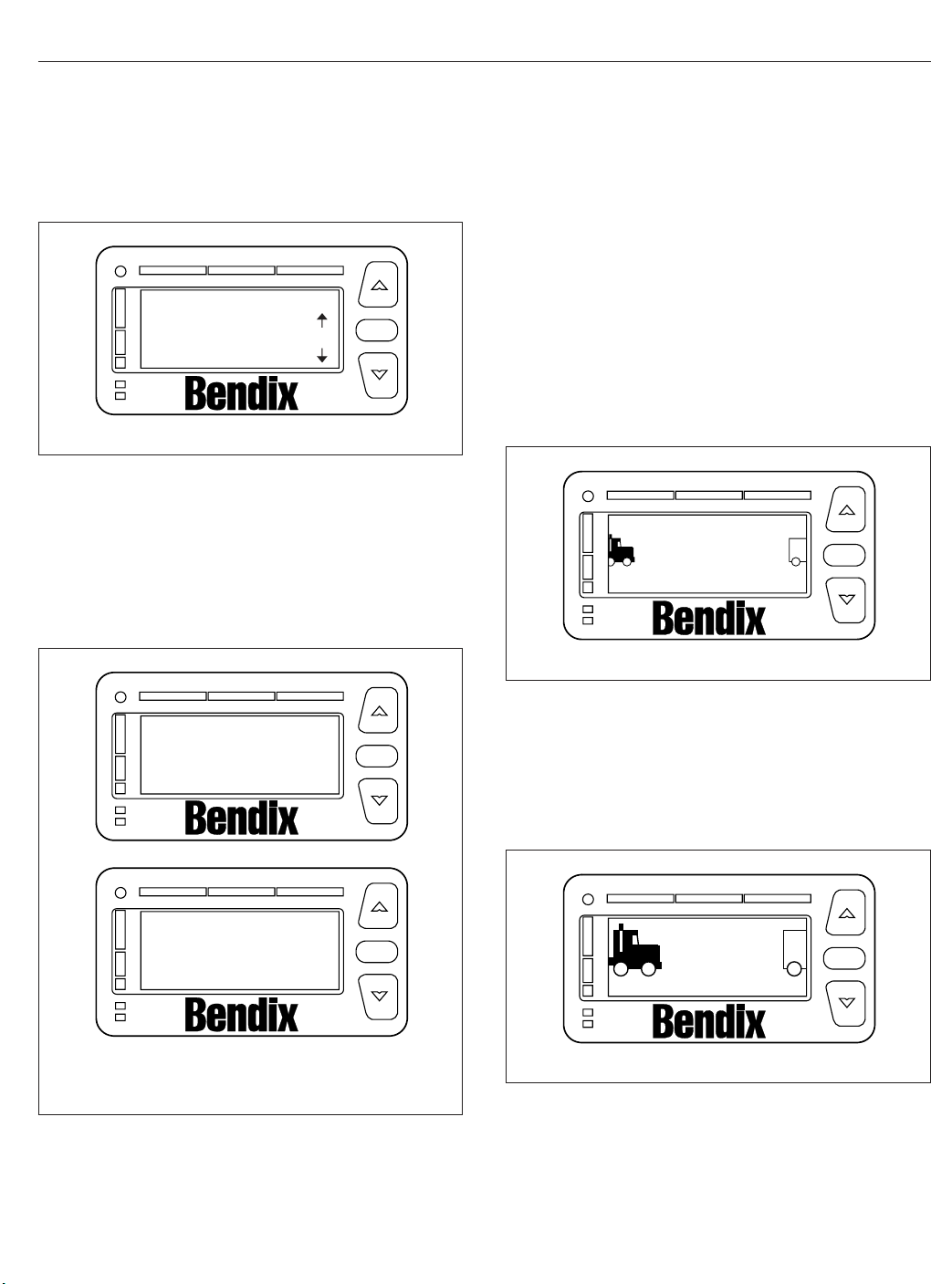
Driver Assistance Features
See Fig. 6.7. Contact an authorized Freightliner service center if fault codes display.
DIU DIAGNOSTICS
SPN: 00886 FMI:012
OK
TM
02/03/2012
Fig. 6.7, DIU Diagnostic Screen
OK
f610929a
Collision Warning System
The CWS may require a warm-up period of up to
one minute if the outside air temperature is below
32°F (0°C). The DIU will display a warm-up message
until the system reaches operating temperature. See
Fig. 6.8.
The alerts given by the VS-400 system are based on
the distance to the object ahead, whenever vehicle
speed is 10 mph (16 km/h) or faster. The VS-400
CWS identifies and tracks the nearest object in the
lane of travel. This object is classified by the range,
and assigned a message described under the following headings.
Object Detected
When a vehicle is detected in the same lane of travel
within 350 ft (107 m) but farther than a 3-second following distance, the DIU will display OBJECT DE-
TECTED. See
02/03/2012
Fig. 6.9.
Object Detected
TM
Fig. 6.9, Object Detected Alert
OK
f610930a
A
B
02/03/2012
A. CWS with
SmartCruise
Fig. 6.8, CWS Warm-Up Screens
Radar Warming Up
Do not use
SmartCruise
Radar Warming Up
Please wait
B. CWS Only
3-Second Headway Alert
OK
TM
OK
TM
f610924a
When a vehicle is detected to be within a 3-second
following distance, a single yellow indicator will illuminate and the DIU will display 3 seconds. See
Fig. 6.10.
3 seconds
TM
02/03/2012
Fig. 6.10, 3-Second Alert
OK
f610931a
6.4
Page 76

Driver Assistance Features
2-Second Headway Alert
When the following distance to the object ahead in
the same lane of travel decreases to within two seconds, a second yellow indicator will illuminate, the
DIU will display 2 seconds, and a single tone will
sound. See
Fig. 6.11.
COLLISION
ALERT
TM
OK
2
seconds
TM
02/03/2012
Fig. 6.11, 2-Second Alert
OK
f610932a
1-Second Headway Alert
When the following distance to the object ahead in
the same lane of travel decreases to within one second, a third yellow indicator will illuminate, the DIU
will display 1 sec, and two tones will sound. See
Fig. 6.12.
1
sec
TM
02/03/2012
Fig. 6.12, 1-Second Alert
OK
f610933a
Collision Alert: ½-Second Headway
When the following distance to the object ahead in
the same lane of travel decreases to 0.5 second, the
red indicators all illuminate across of the DIU, the
DIU will display COLLISION ALERT, and a tone will
sound repeatedly. See
Fig. 6.13.
02/03/2012
Fig. 6.13, Collision Alert
f610934a
SmartCruise
When approaching slower moving traffic with the vehicle’s cruise control engaged, SmartCruise adapts
the engine cruise speed to that of the closest vehicle
ahead, allowing the vehicle to maintain a safe following distance without disengaging the cruise control.
The DIU will display the SmartCruise status screen
indicating the vehicle’s current set cruise speed.
Once the speed of traffic ahead increases beyond
the adapted engine cruise speed, the original cruise
control set speed re-engages.
When SmartCruise is engaged, depressing the accelerator pedal will override the SmartCruise and will
cause the vehicle to accelerate. Depressing the
brake or clutch pedals will deactivate SmartCruise.
When approaching a slow moving or stopped vehicle
ahead, SmartCruise will attempt to maintain the minimum following distance by reducing the engine
cruise speed and engaging the engine brake, if necessary. If SmartCruise is unable to maintain the minimum following distance, the driver will be alerted by
the CWS headway alerts until the driver takes control
or conditions clear.
Side Object Detection
The optional side object detection system may be
installed on one or both sides of the vehicle. The
radar sensor(s) are located on the side of the vehicle, while the sensor display unit is mounted on the
A-pillar. See
The side sensor display unit uses two lights to display the status of the side sensor(s). The yellow light
indicates the system is active, but no objects are detected. The red light indicates that the side sensor
detects an object. If the vehicles turn signal is active
Fig. 6.14.
6.5
Page 77

1
2
3
4
02/06/2012
1. Volume Adjust
2. Red LED–Object Detected
3. Ambient Light Sensor
4. Yellow–No Object Detected
Fig. 6.14, Side Sensor Display Unit
and the sensor detects an object alongside the vehicle, an audible warning tone will sound.
f610935b
Driver Assistance Features
•
On approaching a steep hill, objects above the
beam cannot be detected. Generally, the beam
hitting the road surface does not cause an
alarm.
•
The side sensor only detects objects within its
field of view, next to the tractor. A vehicle behind the field of view will not be detected.
•
The side sensor range is set to detect
average-sized vehicles 2 to 10 feet (0.5 to 3
meters) away in the adjacent lane.
•
The radar beam will detect near range cut-ins
of approximately 30 feet (9 meters) or less,
depending on the angle of entrance into the
lane in front of your vehicle.
•
A continuous fixed object on the right side of
the vehicle such as a guard rail, wall, tunnel, or
bridge may cause the side sensor alert light to
stay on.
WARNING
Special Road Situations
Certain road situations may affect the system’s ability
to detect objects. These situations include the effects
of curves, dips, and hills which can provide an unexpected result.
NOTE: A warning may sound when an object is
detected in front of the vehicle even though the
driver intends to turn away or stop before reaching the object.
•
When an object is detected in a very sharp
right- or left-hand turn, the audible alarm will
not sound.
•
When approaching a curve, alarms may sound
and lights illuminate, because of an object off
the road directly in line with your vehicle. This
will not occur when the brakes are applied.
•
When approaching a roadway descending to a
lower elevation, elevated obstacles such as
overpasses and overhead signs may be detected.
•
Vehicles cannot be detected on the other side
of a hill. An alarm will not sound until the object
is within the antenna assembly’s field of view.
Heavy rain or water spray at the side sensor may
cause both the yellow and red lights on the side
sensor display to illuminate at the same time.
Under these conditions the system is temporarily
unable to provide adequate warnings.
Failure to drive safely and use the system properly could result in personal injury and/or death
and severe property damage.
Maintenance
Keep the antenna and side sensor free of buildup of
mud, dirt, ice, or other debris that might reduce the
system’s range.
Failure Display Mode/Fault Codes
The VS-400 performs internal diagnostics at powerup, then continuously monitors system components
thereafter.
If a failure is detected, depending on what features
are affected, the DIU displays a screen similar to
Fig. 6.15, blinks the orange fault light, and sounds a
tone. Press the OK button to acknowledge the fault.
After the fault has been acknowledged, the DIU will
attempt to return to normal operations. The orange
LED is continuously illuminated while the fault persists. If the fault disappears, the VS-400 transmits a
6.6
Page 78

Driver Assistance Features
VORAD fault
Collision warn FAILED
OK
TM
02/03/2012
Fig. 6.15, VORAD Fault Display
message to indicate that the fault status has
changed to a previously active fault.
In the event the CWS antenna becomes blocked
while the vehicle is moving (e.g., snow, mud, ice,
tampering, etc.), the system sounds a tone and displays the fault screen shown in
Fig. 6.16.
Contact an authorized Freightliner dealer to review
and clear previously active fault codes.
VORAD fault
Radar Blocked
OK
TM
OK
f610936a
OK
The front-looking antenna assembly transmits radar
signals to, and receives them back from, objects
ahead of the vehicle. This allows the determination of
the distance, speed, and angle of the object ahead.
The system uses this information to warn the driver
of potentially dangerous situations.
WARNING
The Meritor WABCO OnGuard™Collision Safety
System is intended solely as an aid for an alert
and conscientious professional driver. It is not
intended to be relied upon to operate a vehicle.
Use the system in conjunction with rearview mirrors and other instruments to safely operate the
vehicle. Operate a vehicle equipped with the OnGuard in the same safe manner as if the CWS
were not present.
The OnGuard Collision Safety System is not a
substitute for safe, normal driving procedures,
nor will it compensate for any driver impairment
such as drugs, alcohol, or fatigue.
The OnGuard Collision Safety System may provide little or no warning of hazards such as pedestrians, animals, oncoming vehicles, or cross
traffic.
Failure to drive safely and use the system properly could result in personal injury and/or death
and severe property damage.
OnGuard Display Unit
02/03/2012
Fig. 6.16, Antenna Blocked Display
f610937a
OnGuard™Collision Safety
System
Meritor WABCO OnGuard is a forward-looking radarbased adaptive cruise control and collision safety
system with active braking. The system includes a
collision warning system (CWS), adaptive cruise control (ACC) with active braking, and a collision mitigation system (CMS).
The system performs in fog, rain, snow, dust, smoke,
and darkness. To be detected, objects must be within
the radar field of view and provide a surface area
that can reflect the radar.
6.7
The OnGuard system controls are located in the display unit. The display provides visual and audible
warnings and messages, as well as verification of
correct system operation and faults. Menu selections
are made by pressing the up and down arrows, and
the MODE button. See
Fig. 6.17.
The display includes:
•
an internal speaker
•
a graphic display
•
buttons to scroll and select options
Collision Warning System (CWS)
The CWS generates audible and visual alerts when
the vehicle’s following distance may result in a collision. The CWS provides only a warning, and will not
control vehicle speed.
Page 79

Driver Assistance Features
230FT
08/30/2011
Fig. 6.17, OnGuard Display Unit
The CWS cannot be disengaged or turned off, and is
always active at vehicle speeds above 15 mph (25
km/h).
f545826
Standby
When no object is detected, the display shows that
the CWS is on and the radar is searching. See
Fig. 6.17.
Object Detected
When an object is detected in the lane ahead, the
display shows that the CWS is on and the radar is
tracking an object at the speed shown. See
Fig. 6.18.
If the following distance between the vehicle and the
object is too close, the CWS will emit an audible alert
and the display background will turn yellow. The alert
will end when vehicle speed drops below the object
speed and the following distance is increased.
Collision Warning
If the object is traveling slower than the driver’s vehicle, the CWS warns of an impending collision by
emitting an urgent audible alert and displaying the
collision warning symbol with a red background. See
Fig. 6.19.
CWS
10/31/2014 f611143
Fig. 6.18, CWS Object Detected
55 MPH
15 FT
CWS 15 MPH
10/31/2014 f611144
Fig. 6.19, CWS Collision Warning
Adaptive Cruise Control (ACC)
ACC is a radar-based system that works in conjunction with conventional cruise control to maintain the
set cruise speed when no vehicle is being tracked,
and maintains a minimum following distance when an
object is being tracked. The minimum following distance is maintained by automatically decelerating the
vehicle using throttle, engine, and service brakes
without driver intervention. When the object is no longer being tracked, the set cruise control speed resumes automatically.
Standby
When no object is detected, OnGuard ACC operates
similarly to conventional cruise control. The cruise
control set speed is shown on the OnGuard display
unit. See
Object Detected
When an object is detected in the lane ahead, the
display shows that ACC is on and the radar is tracking an object at the speed shown. See
Fig. 6.20.
Fig. 6.21.
6.8
Page 80

Driver Assistance Features
15 FT
Set: 60 MPH
10/31/2014 f611145
Fig. 6.20, ACC Standby
230 FT
Set: 60 MPH
10/31/2014 f611146
Fig. 6.21, ACC Object Detected
If the driver uses the accelerator pedal to override
the cruise control and approach a vehicle too closely,
the ACC will emit an audible alert and the display
background will turn yellow. The alert will end when
vehicle speed drops below the object’s speed and
the following distance is increased.
NOTE: The following distance alert does not
operate at speeds below 15 mph (25 km/h).
55 MPH
Set: 60 MPH
10/31/2014 f611147
Fig. 6.22, ACC Collision Warning
collision is developing and the driver does decelerate
the vehicle, OnGuard’s active braking automatically
applies the engine and service brakes to provide
braking power. The active braking application is intended only to provide early braking as the driver is
recognizing and reacting to the situation.
15 MPH
IMPORTANT: CMS and active braking are not
operational at vehicle speeds below 15 mph (25
km/h).
Error Screens
IMPORTANT: The OnGuard collision safety system is not operational when an error screen is
displayed.
If a system fault is detected, the OnGuard display
unit will immediately display an error screen like the
one shown in
ted will be displayed first; additional faults (if any)
can be viewed using the up or down buttons. The
display does not show stored fault codes.
Fig. 6.23. The first error code transmit-
Collision Warning
If the object is traveling more slowly than the driver’s
vehicle, the CWS warns of an impending collision by
emitting an urgent audible alert and displaying the
collision warning symbol with a red background. See
Fig. 6.22.
The braking control will activate and slow the vehicle.
The driver must also initiate braking.
Collision Mitigation System (CMS)
The CMS provides the driver with audible and visual
alerts when the vehicle’s following distance could
result in a rear-end collision. If a potential rear-end
6.9
DATA ERROR
ACC1 Link Error
10/31/2014 f611148
Fig. 6.23, OnGuard Error Screen
Page 81

If a fault occurs or OnGuard fails to properly track a
vehicle, take the vehicle in for service as soon as
possible. Standard cruise control will not function
with an active OnGuard system fault.
Refer to the OnGuard Collision Safety System Maintenance Manual MM-0951 for a full list of faults (
w.Meritor.WABCO.com
).
ww-
IMPORTANT: If the system fails to track an object, look for signs of damage to the radar assembly.
Driver Assistance Features
COMPONENT TEST
Brake Pedal Position
EBS Brake Switch
CCVS Brake Switch
10/31/2014 f611151
37%
ON
ON
Additional Features
Press the MODE button to access the OnGuard display unit additional features from the CWS or ACC
main operating screen. Press the up and down arrows to scroll through each menu, then press the
MODE button to select the value to be changed. In
edit mode, press the up or down arrows to change a
value setting, then press the MODE button to save
the setting. Pressing MODE in each feature screen
advances the display to the next feature.
The Display Control menu allows adjustment of the
alarm volume, LCD brightness, LCD contrast, and
U.S./metric unit conversion. See
Fig. 6.24.
DISPLAY CONTROL
Alarm Volume
Alarm Tone
LCD Intensity
10/31/2014 f611149
Fig. 6.24, Display Control Menu
The component test menu provides verification of
system component operation and acts as a valuable
OnGuard system diagnostic tool. The header will display either COMPONENT TEST or ACC FUNCTION,
depending on the software release version of the OnGuard system. The component test screen shown in
Fig. 6.25 provides access to the following compo-
nents (press the up or down arrows to scroll through
the menu):
•
brake pedal position
10
4
9
Fig. 6.25, Component Test Menu
•
EBS brake switch
•
CCVS brake switch
•
clutch switch
•
park brake switch
•
accelerator pedal position
•
driveline engaged
•
cruise control enable
•
cruise control set speed switch
•
cruise control coast switch
•
cruise control resume switch
•
cruise control accelerate switch
•
cruise control pause switch
Lane Departure Warning
Controls
The Lane Guidance lane departure warning system
monitors the vehicle’s position within the roadway
lane markings and sounds a warning in the cab
when the vehicle is about to stray outside its lane,
provided the turn signal is not on and the vehicle is
traveling at least 37 mph (60 km/h). The system includes a digital camera mounted high near the center
of the windshield inside the cab and speakers that
emit a sound similar to a rumble strip. The sound is
made on the side of the vehicle it’s straying toward,
prompting the driver to respond and steer away from
the sound and back into the center of the correct
lane.
6.10
Page 82

Driver Assistance Features
WARNING
The lane departure warning system is intended
only as an aid for a conscientious and alert
driver. The system may not indicate lane departures under certain conditions. Read carefully the
information in this manual to understand the circumstances under which this system may not
provide adequate lane departure warnings. Do
not rely solely on the system to safely operate
the vehicle. The system does not warn of all possible hazards. For example, the system cannot
prevent an accident if the driver is impaired or
not driving safely.
The lane departure warning system is not a substitute for safe driving procedures.
Failure to drive safely and use the system properly could result in personal injury and/or death
and severe property damage.
The lane departure warning system powers up each
time the ignition is turned to ON. The system conducts a self test, and initiates test tones from the left
speaker and then the right speaker. Once the vehicle
is started and the system is ready, the LED in the
switch illuminates.
Press the LANE ALERT switch to temporarily disable
the lane departure warning system. See
Some vehicles are equipped with a timer that automatically re-enables the warning system after 15
minutes. On all other vehicles, the warning system
will remain disabled until the driver enables the system by pressing the LANE ALERT switch again, or
the ignition is cycled off and then on.
Fig. 6.26.
When the vehicle approaches the lane markings on
either side, the system sense the activation of a turn
signal. If a turn signal has not been activated, the
system initiates the audible warning to alert the driver
that the vehicle is departing its current lane of travel.
The LANE SRCHNG warning light illuminates to indicate the system is not fully functional. When the
warning light is on, the system audible alert may not
indicate a lane departure. Conditions that can cause
the warning light to illuminate include:
•
The system is unable to detect lane markings.
•
Vehicle speed is less than 37 mph (60 km/h).
•
A system problem is detected.
Roll Stability System
The roll stability system may include the roll stability
advisor (RSA) only, or it may also include the roll stability control (RSC).
A decal (
an amber-colored dash indicator light (Fig. 6.28), indicate that the vehicle is equipped with roll stability
system components.
07/11/2003
Fig. 6.27) on the auxiliary dash panel, and
SAFETY INSTRUCTIONS
lamp indicates traction
OR roll control event.
Follow instructions in
driver’s manual.
24−01204−000
f080125
LANE
ALERT
Fig. 6.26, Lane Departure Warning System Disable
Switch
6.11
Fig. 6.27, Roll Stability Decal
f61115601/05/2012
06/26/2003 f602128
Fig. 6.28, Roll Stability Indicator Lamp
Page 83

Driver Assistance Features
Roll Stability Advisor
IMPORTANT: This is not an advance warning
system. The roll stability advisor displays a message only after the driving maneuver is completed.
The roll stability system uses a lateral-acceleration
sensor that monitors rollover risk. Shortly after a
curve, lane change, or other driving maneuver that
results in a rollover-risk detection, a dash warning
light illuminates, an audible tone sounds, and a driver
advisory message is displayed in the driver message
center. The purpose is to advise the driver that the
previous maneuver produced a rollover risk.
The roll stability advisor displays different text messages depending on the severity of the risk of each
occurrence of risky driving. From the highest risk
level to the lowest risk level, the system will sound
an audible alert, and display a message, as shown in
Fig. 6.29.
NOTE: The system will calculate and recommend a speed reduction value. It may be different than the values shown here.
Bring the vehicle to an authorized service facility if a
system failure message is displayed.
Roll Stability Control
WARNING
The Roll Stability Control system is intended only
as an aid for a conscientious and alert driver.
Carefully read the information in this manual to
understand this system and its limitations. The
Roll Stability Control system is not a substitute
for safe driving procedures. Failure to drive
safely, and use the system properly, could result
in personal injury and/or death and property
damage.
The roll stability control system automatically reduces
engine power, applies the engine brake, and/or applies the tractor and trailer brakes when the acceleration sensor detects that the vehicle is at risk of rolling
over. The control can intervene even before an advisory message is displayed.
The dash indicator light illuminates whenever the roll
stability control system intervenes.
MessageMSG
No.
System Fault1
07/25/2008 f040769
Message to Display
WARNING
RAC SYSTEM FAIL
ACTIVE SLOWING
ROLLOVER RISK
VERY HIGH RISK OF
ROLLOVER DETECTED
REDUCE SPEED
AT LEAST 7 MPH
or in metric
REDUCE SPEED
AT LEAST 11 KPH
HIGH RISK OF
ROLLOVER DETECTED
REDUCE SPEED
AT LEAST 7 MPH
or in metric
REDUCE SPEED
AT LEAST 11 KPH
ROLLOVER RISK
DETECTED
REDUCE SPEED
AT LEAST 7 MPH
or in metric
REDUCE SPEED
AT LEAST 11 KPH
HARD BRAKING WITH
ABS ACTIVATED
LOOK AHEAD
BRAKE SOONER
HARD BRAKING
DETECTED
LOOK AHEAD
BRAKE SOONER
LOSS OF TRACTION
ABS ACTIVATED
ROAD SURFACE
MAY BE POOR
Buzzer
Display
Time:
Time:
Seconds
Seconds
41
4 NoneRSC2
19.6 10RSA Level 33
14 5RSA Level 24
8.4 2RSA Level 15
14 0.5HBED Level 36
14 0.5HBED Level 27
14 0.5HBED Level 18
Fig. 6.29, Roll Stability and Hard-Braking Warnings
6.12
Page 84

Driver Assistance Features
Hard-Braking Advisor
The hard-braking advisor uses the information from
the ABS wheel speed sensors to determine when
braking is severe enough to produce lockup at one
or more wheels on the tractor, and/or very rapid vehicle deceleration. Shortly after a hard-braking event
occurs, an advisory message is displayed in the
driver message center, indicating that the braking
behavior was too aggressive for the current road surface conditions. This system is not a replacement for
a driver’s good judgment. Sometimes it is necessary
to brake hard.
From the highest risk level to the lowest risk level,
the system will sound an audible alert, and display a
message, as shown in
Trip/Leg Totals
Fig. 6.29.
TRIP ADVISORIES
237 ROLL 518 BRK
07/25/2008
A. RSA lev. 3 Count (2)
B. RSA lev. 2 Count (3)
C. RSA lev. 1 Count (7)
ABC
Fig. 6.30, Trip Advisor Message Screen
If the count reaches more than 9 occurrences an uparrow symbol will appear, to indicate to the driver
that the count has exceeded 9 counts. See
Fig. 6.31.
DEF
D. HBED lev. 3 Count (5)
E. HBED lev. 2 Count (1)
F. HBED lev. 1 Count (8)
f040770
The driver message center records the number of
messages received, and displays the number of
messages as counts. Roll stability advisor (RSA) and
hard-braking event data (HBED) counts can be
viewed in the trip advisory screen, and the leg advisory screen.
Counts can be reset using the + key on the steering
wheel. Clearing RSA and HBED leg counts will also
reset the leg miles and leg hours. Clearing RSA and
HBED trip counts will also reset trip miles, trip hours,
leg miles, leg hours, and leg advisory counts. In addition, resetting leg miles will clear leg counts. Clearing trip miles will reset miles, hours, and counts in
both the leg and trip screens.
The TRIP and LEG advisor screens count both the
roll stability advisories (ROLL) and hard-braking
events (BRK). For example, if during a TRIP, the
driver message center recorded the events in
Table 6.1, the message center would display as
shown in
Fig. 6.30.
RSA/HBED Count
Message Received Message Counts
RSA Level 3 2
RSA Level 2 3
RSA Level 1 7
HBED Level 3 5
HBED Level 2 1
HBED Level 1 8
Table 6.1, RSA/HBED Count
TRIP ADVISORIES
23 ROLL 518 BRK
07/25/2008
A. RSA Lev. 1 has more than 9 counts.
Fig. 6.31, Trip Advisor Message Screen (more than 9
A
counts)
f040771
Enhanced Stability Control
WARNING
Enhance Stability Control (ESC) is intended only
as an aid for a conscientious and alert driver.
Carefully read the information in this manual to
understand this system and its limitations. ESC
is not a substitute for safe driving procedures.
Failure to drive safely, and use the system properly, could result in personal injury and/or death
and property damage.
ESC offers the full capability of RSC (shown above)
with the added capability of complete directional stability (yaw control) in oversteer and understeer conditions to reduce the likelihood of drift-out or jackknife.
The system determines where the driver is attempting to steer the vehicle and how much brake demand
is required in order to more precisely control the vehicle in an emergency situation.
6.13
Page 85

ESC works by constantly comparing the driver’s intention with the vehicle’s actual behavior. The system
does this by monitoring systems such as wheel
speed, steering angle, yaw rate, lateral acceleration,
throttle position, and brake application. A central microcomputer analyzes the collected data and triggers
a response to keep the vehicle on course when an
unstable condition is detected.
When the system detects that the vehicle is at risk of
oversteering or understeering, it applies individual
tractor wheel end brakes and trailer brakes, activates
the engine retarder (if equipped), and/or cuts engine
power, depending on the severity. As a result, the
driver has full control over the vehicle until the system detects a potential risk and intervenes accordingly. ESC operates automatically; the driver does
not monitor or activate the system.
Driver Assistance Features
6.14
Page 86

7
Seats and Restraints
Seats, General Information ......................................................... 7.1
Cascadia 2.0 High-Back Seat ....................................................... 7.2
Cascadia High-Back Seat .......................................................... 7.3
Sears Atlas Seat .................................................................. 7.4
Seat Belts and Tether Belts ......................................................... 7.5
Steering Wheel Air Bag ............................................................ 7.8
RollTek Rollover Protection System .................................................. 7.9
Page 87

Seats and Restraints
Seats, General Information
Unless otherwise noted, all seat adjustments should
be made while seated and before the engine is
started.
Due to the high degree of adjustability of mid- and
high-back air suspension seats, it is possible to combine the seat back recline adjustment and the seat
slide adjustment so that the seat back contacts the
back wall. Use care when adjusting the seat to prevent damage to the seat and the cab interior.
WARNING
Keep hands, tools, and other objects away from
the scissor points under the seats. Failure to do
so could cause personal injury.
The following is a description of adjustments that can
be made to various Freightliner-installed seats. Not
all seats have all of the adjustments listed below.
See
Fig. 7.1.
•
Backrest Tilt enables the backrest to pivot forward or backward.
•
Lumbar Support changes the shape of the
backrest to give more or less support to the
occupant’s lumbar (lower back) area. This adjustment is either mechanical or air controlled,
depending on the seat model.
•
Fore/Aft Isolator feature reduces the amount of
road shock by isolating the occupant from the
motion of the vehicle, and allowing the upper
seat to move in a simple pendulum motion. A
lockout feature is used whenever the isolator is
not desired.
•
Height Adjustment moves the entire seat up or
down. The adjustment is either manually- or
air-controlled, depending on the seat model.
•
Bottom Cushion Angle (fore-and-aft bottom
cushion height)
enables the occupant to raise
or lower the front or back of the bottom cushion. This adjustment is easier to perform when
all weight is removed from the seat.
•
Fore/Aft Seat Slide (seat track adjustment)
moves the entire seat forward or backward on
its track.
1
5
10/26/2000
1. Backrest Tilt
2. Lumbar Support
3. Fore/Aft Isolator
4. Height Adjustment
7.1
3
2
6
5. Bottom Cushion Tilt (fore-and-aft
cushion height)
6. Fore/Aft Seat Slide (seat track
adjustment)
Fig. 7.1, General Seat Adjustments
4
8
7
f910149a
7. Seat Tilt
8. Headrest Adjustment
Page 88

•
Seat Tilt allows the seat assembly (back and
bottom cushions) to tilt forward or backward.
•
Headrest Adjustment changes the angle of the
upper part of the backrest to provide head and
upper back support.
Cascadia 2.0 High-Back Seat
Fig. 7.2 for seat adjustment controls. Not all
See
models of the Cascadia 2.0 Hi-Back seat have all the
adjustments listed below.
Recline
Pull the recline handle to adjust the backrest tilt.
Seat Heating/Ventilation
Use the forward switch to turn the seat heater and
ventilation ON or OFF. To turn on the heat, push the
top of the switch. To turn on the ventilation, push the
bottom of the switch. To turn off the heat or ventilation, move the switch to the middle position. To adjust the heat or ventilation, Use the rear button to
adjust seat heating or ventilation. Three settings are
available: low, medium, and high. See
NOTICE
Do not install seat covers on seats with heating
and ventilation. Do not cover the seat with blankets, clothing, or pillows. Blocking the air flow
through the cushions can overheat and damage
the seat.
IMPORTANT: Turn off seat heating/ventilation
when the seat is unoccupied.
Lumbar Support
Press the forward button to adjust lower lumbar support, the middle button to adjust upper lumbar support, and the rear button to adjust side support.
Fig. 7.3.
Seats and Restraints
1
2
10
9
8
05/11/2012 f910682
1. Recline Handle
2. Heat/Ventilation Adjustment Switch
3. Heat/Ventilation ON/OFF Switch
4. Lumbar and Side Support Switches
5. Height Adjustment Lever
6. Shock Absorber Adjustment Lever
7. Fore/Aft Isolator Lever
8. Bottom Cushion Extension Lever
9. Seat Fore/Aft Slide Lever
10. Seat Tilt Lever
Fig. 7.2, Cascadia 2.0 Hi-Back Seat
7
6
3
4
5
Height Adjustment
Pull or push the lever to adjust seat height.
Shock Absorber Adjustment
Move the lever down to increase damping on rough
roads, or up to decrease damping on flat roads.
Fore/Aft Isolator
Rotate the isolator knob to the left to lock the isolator, or to the right to allow movement.
7.2
Page 89

Seats and Restraints
45
3
2
1
05/08/2012 f910683
1. Ventilation ON
2. Heat/Ventilation OFF
3. Heat ON
4. Heat/Ventilation ON/OFF Switch
5. Heat/Ventilation Adjustment Switch
Fig. 7.3, Cascadia 2.0 Hi-Back Seat Heat/Ventilation
Controls
Bottom Cushion Extension
Pull the lever to move the seat cushion forwards or
backwards. The cushion moves 2-3/8 inches (60
mm) in 3/8-inch (10-mm) increments.
Seat Fore/Aft Slide
Lift the lever to slide the seat forward or backward.
Release the lever to lock the seat in position.
Seat Tilt
Pull the lever and lean back to tilt the seat backwards. Three positions are available.
Armrest Angle
Lumbar Support
To adjust the lumbar support, use the lumbar support
switches on the side of the seat.
Height Adjustment
To raise or lower the height of the seat, use the
height adjustment switch on the side of the seat.
Bottom Cushion Extension
To adjust the fore-and-aft position of the seat cushion, remove your weight from the seat, then lift up
and pull forward on the cushion adjustment handle.
To return the cushion to the aft position, lift up and
push rearward.
Fore/Aft Seat Slide
To adjust the fore-and-aft position of the entire seat,
move the fore-and-aft seat adjustment lever to the
left and slide the seat forward or backward to the
desired position. Move the lever back to its original
position to lock the seat in place.
Fore/Aft Isolator
To engage the isolator, turn the isolator knob rearward to the unlocked position. Turn the isolator knob
forward to the locked position when the isolator feature is not desired.
Shock Absorber
To adjust the amount of damping the shock absorber
provides, move the lever up to increase damping;
move the lever down to decrease damping.
To adjust the armrest angle, tilt the armrest to the
highest position, then down to the lowest position,
then to the desired position.
Cascadia High-Back Seat
Fig. 7.4 for seat adjustment controls.
See
Backrest Tilt
To tilt the backrest, lean forward slightly to remove
pressure from the cushion, then turn the knob forward or rearward to achieve the desired position.
7.3
Front Cushion Height
To adjust the height of the front of the cushion, remove your weight from the seat, then turn the adjustment knob toward the front of the seat (clockwise) to
increase cushion height. To lower the cushion height,
turn the adjustment knob toward the rear of the seat
(counterclockwise).
Rear Cushion Height
To adjust the height of the rear of the seat cushion,
remove your weight from the seat and turn the rear
cushion adjustment knob to one of three positions.
Page 90

Seats and Restraints
1
2
3
07/18/2007
1. Rear Cushion Height Adjustment
Knob
2. Fore/Aft Isolator
3. Front Cushion Height Adjustment
Knob
4. Bottom Cushion Extension Handle
5. Fore/Aft Seat Slide Lever
6. Backrest Tilt Knob
7. Heater Button
Fig. 7.4, Cascadia Hi Back Seat
Heater
To turn on the heat option, press the button. To turn
off the heat option, press the button again. If the vehicle has Optimized Idle, seat heating will not operate with the key in accessory mode. Optimized Idle
may also turn seat heating off to reduce stress on
the batteries. Refer to
Chapter 11 for more informa-
tion.
Sears Atlas Seat
Fig. 7.5 for seat adjustment controls.
See
6
4
5
8. Shock Absorber Lever
9. Height Adjustment Switch
10 Lumbar Support Switches
8
7
Backrest Tilt
Pull upward on the recliner handle, move the backrest to the desired position and release the handle.
Lumbar Support
Rear rocker switch: Push forward to inflate the lower
lumbar bag; push rearward to deflate the bag. Center
rocker switch: Push forward to inflate the upper lumbar bag; push rearward to deflate the bag.
Fore/Aft Seat Slide
To adjust the fore-and-aft position of the entire seat,
squeeze the fore/aft slide lock against the adjustment
bail, and lift the bail up. See
Fig. 7.6. Slide the seat
10
9
f910576
7.4
Page 91

Seats and Restraints
A
5
4
3
2
1
10/15/2007 f910597
1. Isolator Lever
2. Fore/Aft Seat Slide
Lever
3. Bottom Cushion Tilt
Handle
4. Seat Extension Lever
Fig. 7.5, Sears Atlas Seat
forward or backward to the desired position. Release
the bail and fore/aft slide lock, to its original position,
to lock the seat in place.
5. Backrest Tilt Lever
6. Lumbar Support
Switches
7. Suspension Inflation/
Deflation Switch
6
7
Bottom Cushion Tilt
Lift the handle upward and move the seat cushion to
the desired position. Three positions are available.
10/15/2007 f910599
A. Squeeze the fore-and-aft slide lock against the
adjustment bail.
B. Lift up the adjustment bail.
Fig. 7.6, Fore/Aft Slide Adjustment, Sears Atlas Seat
B
Armrest Angle
Rotate the control knob, located on the underside of
the armrest, to set the desired angle of the armrest.
Isolator
Position the handle to the left to allow isolation
movement. Position the handle to the right to lockout isolation movement.
Suspension Inflation/Deflation
Push forward on the gray rocker switch to inflate and
raise the suspension; push rearward to deflate and
lower the suspension.
Seat Extension
Rotate the handle upward to disengage, then move
the seat cushion to the desired position and release
the lever. Three positions are available.
Seat Belts and Tether Belts
Seat belt assemblies are designed to secure persons
in the vehicle to help reduce the chance of injury, or
the amount of injury, resulting from accidents or sudden stops. For this reason, Daimler Trucks North
America LLC (DTNA) urges that the driver and all
passengers, regardless of age or physical condition,
use seat belts when riding in the vehicle.
7.5
Page 92
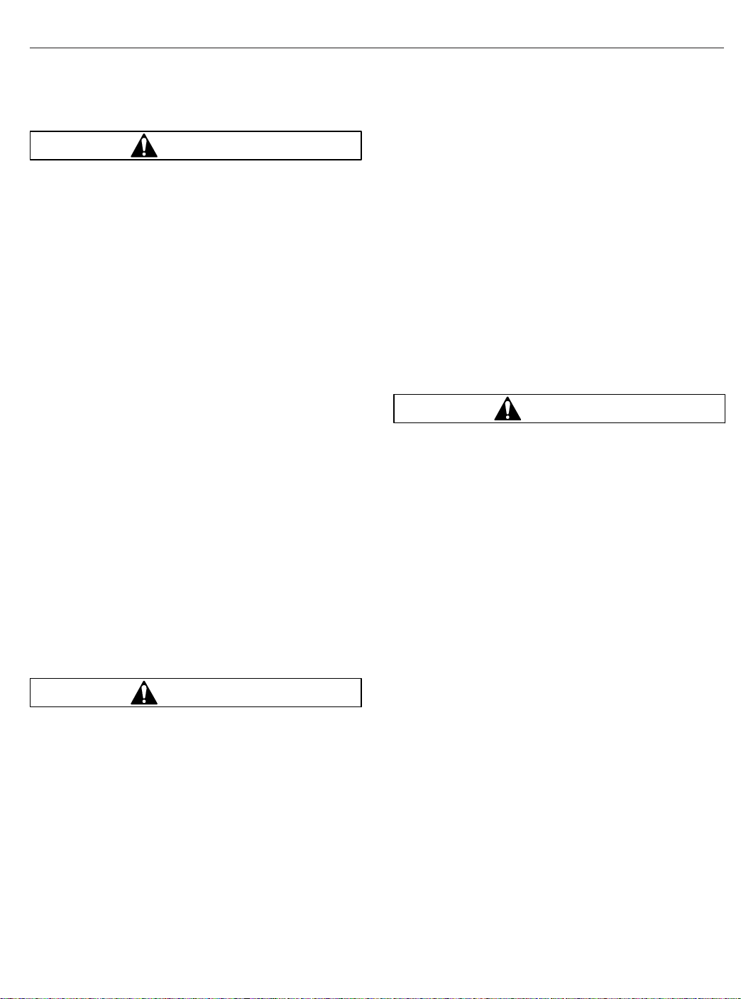
Seats and Restraints
WARNING
Always use the vehicle’s seat belt system when
operating the vehicle. Failure to do so can result
in severe personal injury or death.
Seat belt assemblies in DTNA vehicles meet Federal
Motor Vehicle Safety Standard 209, "Type 1" and
"Type 2" requirements.
When transporting a child, always use a child restraint system or the vehicle seat belts as appropriate. To determine whether a child restraint system is
required, review and comply with applicable state
and local laws. Any child restraint used must comply
with Federal Motor Vehicle Safety Standard 213,
"Child Restraint Systems." When providing a child
restraint system, always carefully read and follow all
instructions pertaining to installation and usage for
the child. Make certain the child remains in the restraint system at all times when the vehicle is in
motion.
In addition to seat belt assemblies, tether belts are
installed on suspension-type seats. Tether belts help
secure the seat to the floor and are intended to restrain the seat and seat belt in case of an accident or
sudden stop.
IMPORTANT: Seat belts have a finite life which
may be much shorter than the life of the vehicle.
Regular inspections and replacement as needed
are the only assurance of adequate seat belt
security over the life of the vehicle.
Seat Belt Inspection
WARNING
Inspect and maintain seat belts. When any part of
a seat belt system needs replacement, the entire
seat belt must be replaced, both retractor and
buckle side. Any time a vehicle is involved in an
accident, and the seat belt system was in use,
the entire vehicle seat belt system must be replaced before operating the vehicle. Do not attempt to modify the seat belt system; doing so
could change the effectiveness of the system.
Failure to replace worn or damaged seat belts, or
making any modifications to the system, may result in personal injury or death.
Inspect the seat belts and tether belts (if so
equipped).
1.
Check the web for fraying, cuts, extreme dirt and
dust, or for severe fading from exposure to sunlight, especially near the buckle latch plate and in
the D-loop guide area.
2.
Check operation of the buckle, latch, Komfort
Latch or Sliding Komfort Latch (if equipped), web
retractor, and upper seat belt mount on the door
pillar. Check all visible components for wear or
damage.
3.
Check the seat belt and tether belt connection
points and tighten any that are loose.
Seat Belt Operation
WARNING
Wear three-point seat belts only as described
below. Three-point seat belts are designed to be
worn by one person at a time. In case of an accident or sudden stop, personal injury or death
could result from misuse.
Fasten the seat belts before driving. Fastening a
three-point seat belt while driving creates a hazard.
When engaged and used properly, the Komfort Latch
Fig. 7.7) and the Sliding Komfort Latch (Fig. 7.8)
(
introduce a small amount of slack into the seat belt,
resulting in a more comfortable ride.
1.
Slowly pull the link end of the seat belt out of the
retractor and pull it across your lap (from outboard to inboard) far enough to engage the
buckle. If the retractor locks too soon, allow the
belt to retract slightly, then slowly pull it out
again. See
2.
Fasten the seat belt by pushing the latch into the
buckle. Listen for an audible click.
3.
Tug on the seat belt to make sure it is securely
fastened. If the buckle unlatches, repeat this
step. If the problem continues, replace the seat
belt.
4.
Snug the seat belt to your waist.
Fig. 7.9.
7.6
Page 93

Seats and Restraints
A
03/11/2010 f910620
A. Disengaged B. Engaged
Fig. 7.7, Komfort Latch
11/18/2010 f910621a
Fig. 7.8, Sliding Komfort Latch
B
WARNING
Before activating the Komfort Latch or the Sliding Komfort Latch, make sure the amount of
1
2
07/02/2007 f910578
1. Latch 2. Buckle
Fig. 7.9, Three-Point Seat Belt Operation
slack in the shoulder strap is set as described
below. Excess slack in the shoulder strap reduces the effectiveness of the seat belt, and increases the risk of injury or death in an accident.
5.
Position the shoulder strap diagonally across
your chest with the adjustable D-loop bracket (if
equipped). The shoulder strap must be centered
on your shoulder and chest, away from your face
and neck. See
Fig. 7.10. If desired, engage the
Komfort Latch or Sliding Komfort Latch as follows.
If equipped with a Sliding Komfort Latch, make
sure that the shoulder strap is snug against your
chest. Without loosening the shoulder strap,
push the Sliding Komfort Latch switch to the
"ON" position. See
Fig. 7.8. To activate the latch
lean forward until you hear a click. This will allow
7.7
Page 94

for approximately 1 inch (2.5 cm) of slack between your chest and the shoulder harness.
Once engaged, the latch will allow you to lean
forward about 5 inches (13 cm) without having to
reset the latch. Leaning forward more than 5
inches (13 cm) will disengage the Sliding Komfort Latch, requiring it to be reset.
If equipped with a Komfort Latch, pull on the
shoulder strap to lessen the pressure of the strap
on your shoulder and chest. Allow no more than
1 inch (2.5 cm) of slack between your chest and
the shoulder harness. More slack can significantly reduce the seat belt effectiveness in an
accident or a sudden stop. While holding the belt
slack, press the Komfort Latch lever up, clamping the seat belt webbing (
Fig. 7.11 and
Fig. 7.12).
Seats and Restraints
A
01/06/95
A. 1 Inch (2.5 cm) Maximum
Fig. 7.11, Adjusting Shoulder Harness Clearance,
Komfort Latch
f910048a
08/09/2010
A. Correct—Belt is centered on your shoulder and
B. Wrong—Belt must not rub against face or neck.
C. Wrong—Belt must not hang off shoulder.
6.
ABC
f910634
chest, away from your face and neck.
Fig. 7.10, Proper Shoulder Strap Fit
Unbuckle the seat belt and release the Komfort
Latch or the Sliding Komfort Latch as follows.
If equipped with a Sliding Komfort Latch, unbuckle the seat belt, then tug on the shoulder
belt to release the Sliding Komfort Latch,
or
press the Sliding Komfort latch to the "OFF" position, then unbuckle the seat belt.
If equipped with a Komfort Latch, unbuckle the
seat belt, then release the Komfort Latch by giving the shoulder belt a quick tug. If you lean forward against the shoulder belt, the Komfort Latch
will automatically release, and will need to be
reset.
NOTE: Neither the Komfort Latch nor the Sliding
Komfort Latch need to be manually released in
an emergency situation. Each will release by
11/02/95
Fig. 7.12, Locking the Komfort Latch
f910144
itself under rough road or other abnormal conditions. Make sure the seat belt is completely retracted when it is not in use.
Steering Wheel Air Bag
Operation
NOTE: Only vehicles with the letters "SRS"
molded into the steering wheel center pad are
equipped with a steering wheel air bag.
The air bag, when used with seat belts, provides additional protection to the driver in severe frontal collisions. Steering wheel air bags are designed to inflate
only in severe frontal collisions. The driver and the
7.8
Page 95

Seats and Restraints
passenger should always wear seat belts. The steering wheel air bag will activate during a collision even
if the seat belts are not fastened, but the system is
designed to provide protection to the occupant only
when the seat belts are fastened.
WARNING
Keep all heavy objects in the cab secured. Do not
place objects on the steering wheel or between
you and the steering wheel. Any such objects
may cause harm during an accident. Keep your
hands on the sides and lower portion of the
steering wheel. Failure to follow these instructions may result in death or personal injury.
For maximum protection in a collision, always be in a
normal seated position with your back against the
seat back and your head upright. Fasten your seat
belt and ensure that it is properly positioned on your
body as described under the "Seat Belt Operation"
heading. Since the air bag inflates with considerable
speed and force, a proper seat position will help
keep you a safe distance from the inflating air bag.
Inspection and Service
WARNING
Do not attempt to service or modify the air bag
system. Unintentional or improper air bag deployment could cause severe bodily injury or death.
Contact an authorized Freightliner service facility
for all service and maintenance.
The air bag system contains components that
use combustible chemicals. Do not cut, drill,
braze, solder, weld, strike, or probe the air bag
components. Keep all liquids and chemicals
away from air bag components.
The surface of the deployed air bag may contain
small amounts of sodium hydroxide (which is a
by-product of the gas generant combustion) and
metallic sodium. Sodium hydroxide may be irritating to the skin and eyes. Immediately wash
your hands and exposed skin areas with a mild
soap and water. Flush your eyes immediately if
exposed to sodium hydroxide.
The operational readiness of the air bag system is
indicated by the supplemental restraint system (SRS)
indicator on the dash. The SRS indicator illuminates
for several seconds when the ignition is turned on,
and then it goes off. The indicator will remain on if
there is a problem with the air bag system. The vehicle should be serviced if the SRS indicator does
not illuminate when the ignition is turned on, or if the
SRS indicator remains on.
The air bag module may contain perchlorate material; for information, see
hazardouswaste/perchlorate
apply; follow appropriate rules and regulations when
disposing of materials.
For all service and maintenance, contact an authorized Freightliner service facility.
www.dtsc.ca.gov/
. Special handling may
RollTek Rollover Protection
System
Identification
Only seats with the RollTek module under the seat
and the molded side-roll air bag cover on the upper
side of the seat back are equipped with the RollTek
rollover protection system; see
may be installed in one of the following configurations:
•
driver seat only or driver and passenger seats
•
driver seat only, with an optional steering
wheel frontal air bag
•
driver and passenger seats, with an optional
steering wheel frontal air bag
Operation
The RollTek system, when used with seat belts, provides additional protection to the driver and passenger (if equipped with a passenger-side system) in
rollover accidents. The RollTek system provides a
significant increase in seat stability during a rollover.
Vehicles equipped with RollTek rollover protection
have a sensor mounted in the seat base that activates the side-roll air bag and seat pull-down device
during a rollover.
When the RollTek module senses a rollover, the
module triggers gas cylinders mounted in the base of
the seat. The gas cylinders activate the power
cinches that then tighten the lap and shoulder belts
against the occupant of the seat and lower the seat
suspension, moving the occupant down and away
from the steering wheel and ceiling. The side-roll air
Fig. 7.13. RollTek
7.9
Page 96

Seats and Restraints
2
A
B
10/15/2007 f910598
1. RollTek Module
2. Side-Roll Air Bag Cover
Fig. 7.13, RollTek Protection System Components
1
bag deploys from the outboard side of the seat as
the seat is pulled down to its lowest position. See
Fig. 7.14.
WARNING
Always use the seat belts when operating the vehicle. Failure to do so can result in severe personal injury or death. Do not place infants and
children in seats equipped with the RollTek system. The RollTek system is designed for adults
only. Doing so could result in severe bodily injury or death. Keep all heavy objects in the cab
secured. Do not place objects on the seat back
07/03/2007
A. Side-roll air bag contained in seat.
B. Side-roll air bag deployed.
Fig. 7.14, Side-Roll Air Bag
f910579
or block the side-roll air bag. Objects that block
the side-roll air bag may prevent proper inflation
and could result in serious injury or death.
The RollTek system will activate during a rollover
even if the seat belts are not fastened, but the
RollTek system is only designed to provide protection
to the occupant when the seat belts are fastened.
For vehicles with the RollTek system(s) only, device(s) deploy as follows:
•
Rollover Crash—occupant seat belt pretensioning, seat pretensioning, and side-roll air bag at
the proper time
•
Frontal Crash—no devices deployed
7.10
Page 97

Seats and Restraints
For vehicles with the RollTek system(s) and frontal
steering wheel air bag, device(s) deploy as follows:
•
Rollover Crash—occupant seat belt pretensioning, seat pretensioning, and side-roll air bag at
the proper time
•
Frontal Crash—steering wheel air bag, occupant seat belt pretensioning, seat pretensioning, and the side-roll air bag at the proper time
Inspection and Service
WARNING
Keep hands and tools away from the scissor
points under the seats.
The RollTek system contains components that
use combustible chemicals. Do not cut, drill,
braze, solder, weld, strike, or probe any part of
the RollTek system. Keep all liquids and chemicals away from the RollTek components.
Do not attempt to service or modify the RollTek
system. Unintentional or improper deployment of
the RollTek system could cause severe bodily
injury or death. Contact an authorized Freightliner service facility for all service and maintenance.
IMPORTANT: The RollTek system must be replaced after being activated. Damaged seat
belts and tethers, or seat belts and tethers that
were worn in an accident, must be replaced,
and their anchoring points must be checked.
The operational readiness of the RollTek system is
indicated by the supplemental restraint system (SRS)
indicator on the dash. The SRS indicator illuminates
for several seconds when the ignition is turned on,
and then it goes off. The indicator will remain on if
there is a problem with the air bag or RollTek system. The vehicle must be serviced if the SRS indicator does not illuminate when the ignition is turned on,
or if the SRS indicator remains on.
The air bag module may contain perchlorate material; for information, see
hazardouswaste/perchlorate
apply; follow appropriate rules and regulations when
disposing of materials.
For all service and maintenance, contact an authorized Freightliner service facility.
www.dtsc.ca.gov/
. Special handling may
7.11
Page 98

8
Climate Control
Cab Climate Control Panel ......................................................... 8.1
Sleeper Climate Control Panel ...................................................... 8.2
ParkSmart™HVAC System ......................................................... 8.3
Accessory Heaters ................................................................ 8.5
Page 99

Climate Control
Cab Climate Control Panel
The standard cab climate control panel has a fan
switch with a recirculation button, temperature control
switch with an A/C button, and a mode control
switch. See
with a bunk override button.
07/20/2006 f831701
1. Fan Switch
2. Temperature Control Switch
3. Mode Control Switch
Fan Switch
The fan switch activates the fan, which forces fresh
air or recirculated air through the air outlets. The fan
switch has eight fan speed settings and an OFF position. See
Fig. 8.1. Sleeper cabs are also equipped
12
4
6
2
8
0
Fig. 8.1, Cab Climate Control Panel
Fig. 8.2.
3
To operate the fan switch, turn the fan switch clockwise to increase airflow; turn the fan switch counterclockwise to decrease airflow.
There is a two-second delay between the time the
engine is started and the blower is operational. It can
take an additional four seconds for the blower to
reach high speed. The blower motor performs a selftest immediately after the engine is started, which
causes the delay. If the vehicle has Optimized Idle,
the fan will not operate with the key in accessory
mode. Optimized Idle may also turn the fan off to
reduce stress on the batteries. Refer to
for more information.
Chapter 11
Recirculation
Recirculation mode limits the amount of outside air
entering the cab. Press the recirculation button to
prevent dusty or smoky air from entering the cab.
See
Fig. 8.2. Recirculation mode can also decrease
the time required to cool or heat the cab interior during extreme outside temperature conditions. When
the recirculation mode is turned on, the amber indicator on the recirculation button will illuminate.
The recirculation button will not work when the mode
control switch is in either defog or defrost modes.
NOTE: To prevent the buildup of odors or oxygen depletion inside the cab, the system
switches from full recirculation mode to partial
recirculation mode after 20 minutes. In extremely dusty or smoky conditions, the partial
recirculation mode can be overridden by pressing the recirculation button twice to obtain full
recirculation mode. This resets the 20-minute
timer.
1
06/08/2007 f610946
1. Recirculation Button
Fig. 8.2, Fan Switch
8.1
Temperature Control Switch
The temperature control switch is used to select the
desired temperature in the cab. Turn the switch
counterclockwise for cool air, or clockwise for hot air.
See
Fig. 8.3.
Air Conditioning Button
The air conditioner (A/C) cools and dehumidifies the
air inside the cab. Press the A/C button, located in
the center of the temperature control switch, to turn
the air conditioner on and off. See
A/C will be automatically disabled when:
Fig. 8.3.
Page 100
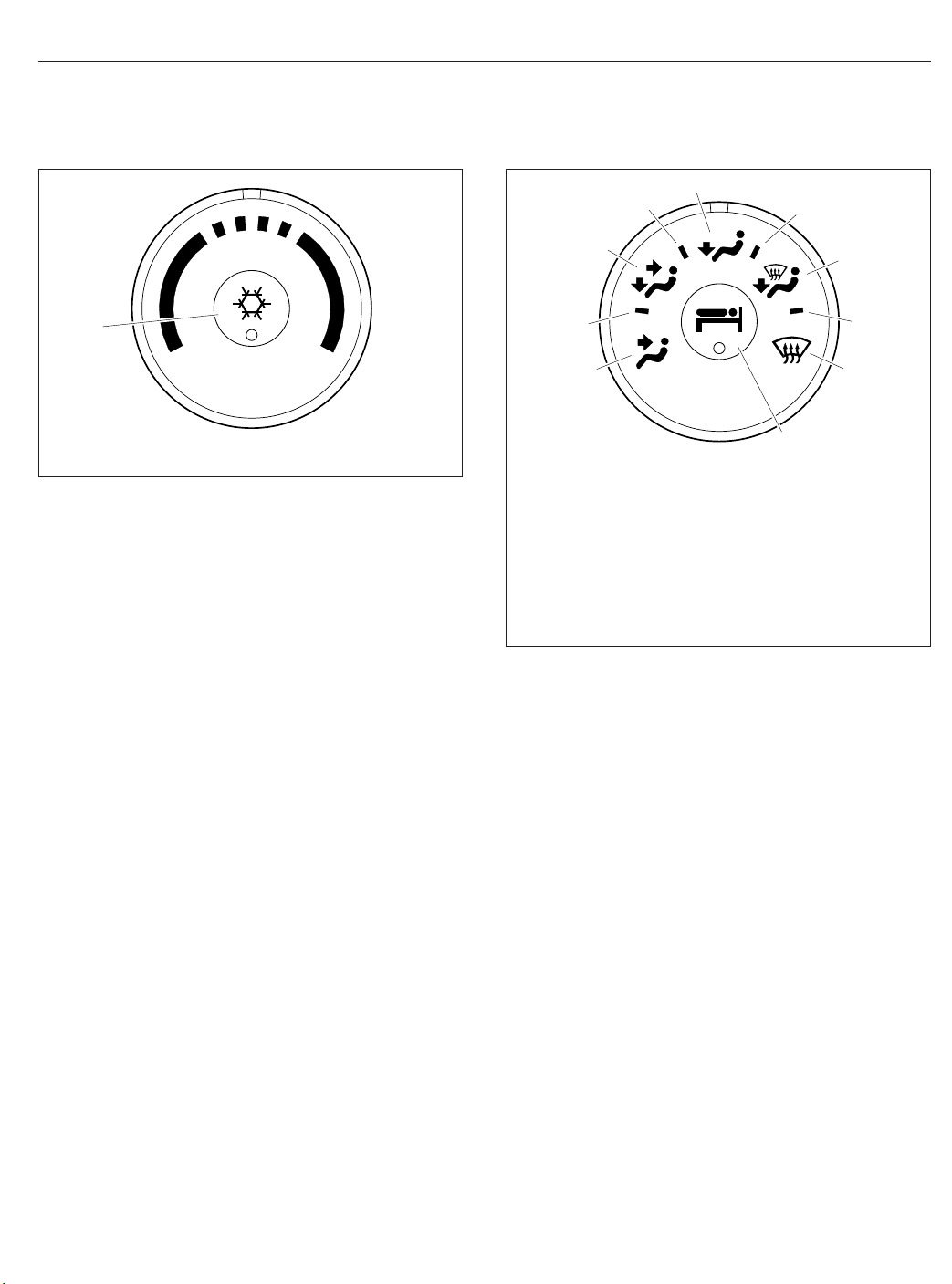
Climate Control
5
4
6
1
06/08/2007 f610947
1. Air Conditioning Button
Fig. 8.3, Temperature Control Switch
•
outside air temperature is low enough to make
the A/C ineffective;
•
engine is running at extremely low rpm;
•
conditions exist that result in the climate control system going into protection mode.
Mode Control Switch
The mode control switch allows the driver to control
the flow of air through the face outlets, the floor outlets, the defrost (windshield) outlets, or a combination
of these outlets. See
•
Face Mode: Directs all airflow through the face
or instrument panel outlets.
•
Bi-Level Mode: Directs the airflow equally to
the face outlets and the floor outlets.
•
Floor Mode: Directs all airflow through the floor
outlets.
•
Floor/Defrost Mode: Directs the airflow equally
to the floor outlets and the defrost outlets.
•
Defrost Mode: Directs all airflow through the
defrost outlets.
Fig. 8.4.
3
2
1
06/08/2007 f610948
1. Face Mode
2. Selection Between Face Mode and Bi-Level Mode
3. Bi-Level Mode
4. Selection Between Bi-Level Mode and Floor Mode
5. Floor Mode
6. Selection Between Floor Mode and Defog Mode
7. Defog Mode
8. Selection Between Defog Mode and Defrost Mode
9. Defrost Mode
10. Bunk Override Button (on sleeper-cabs only)
Fig. 8.4, Mode Control Switch With Bunk Override
Button
10
7
8
9
Press the bunk override button again to turn bunk
override mode off. Adjusting the sleeper climate controls at any time will also cause the bunk override
mode to cancel.
Sleeper Climate Control Panel
The standard sleeper climate control panel has a fan
switch and a temperature control switch with an A/C
button.
If the bunk override button has been activated, the
override mode can be canceled by changing the
sleeper fan speed or temperature setting. The climate control system will then operate from the
sleeper controls.
Bunk Override Button
The bunk override button, equipped on sleeper cabs
only, allows the driver to control the sleeper heat and
A/C settings from the cab. See
Press the bunk override button to turn the sleeper
heat or A/C on. An amber indicator will illuminate
when bunk override mode is activated.
Fig. 8.4.
Fan Switch
The fan switch activates the fan, which forces air
through the air outlets. The fan switch has eight fan
speeds and an OFF position. See
To operate the fan switch, turn the switch clockwise
to increase airflow; turn the fan switch counterclockwise to decrease airflow. If the vehicle has Optimized
Fig. 8.5.
8.2
 Loading...