

ARGOSY
®
STI-385-2
A24-00879-000
Driver’s Manual

Foreword
Introduction
This manual provides information needed to operate
and understand the vehicle and its components.
More detailed information is contained in the Owner’s
Warranty Information for North America booklet, and
in the vehicle’s workshop and maintenance manuals.
Custom-built Freightliner vehicles are equipped with
various chassis and cab components. Not all of the
information contained in this manual applies to every
vehicle. For details about components in your vehicle, refer to the chassis specification pages included in all new vehicles and to the component information label, located inside the vehicle.
For your reference, keep this manual in the vehicle
at all times.
IMPORTANT: Descriptions and specifications in
this manual were in effect at the time of printing.
Freightliner Trucks reserves the right to discontinue models and to change specifications or
design at any time without notice and without
incurring obligation. Descriptions and specifications contained in this publication provide no
warranty, expressed or implied, and are subject
to revisions and editions without notice.
if an air bag is installed, or if the vehicle features a
collision avoidance system, etc.).
Customer Assistance Center
Having trouble finding service? Call the Customer
Assistance Center at 1-800-385-4357 or 1-800-FTLHELP. Call night or day, weekdays or weekends, for
dealer referral, vehicle information, breakdown coordination, or Fleetpack assistance. Our people are
knowledgeable, professional, and committed to following through to help you keep your truck moving.
Environmental Concerns and
Recommendations
Whenever you see instructions in this manual to discard materials, you should first attempt to reclaim
and recycle them. To preserve our environment, follow appropriate environmental rules and regulations
when disposing of materials.
Event Data Recorder
This vehicle is equipped with one or more devices
that record specific vehicle data. The type and
amount of data recorded varies depending on how
the vehicle is equipped (such as the brand of engine,
© 2007–2015 Daimler Trucks North America LLC. All rights reserved. Daimler Trucks North America LLC is a Daimler
company.
No part of this publication, in whole or part, may be translated, reproduced, stored in a retrieval system, or transmitted
in any form by any means, electronic, mechanical, photocopying, recording, or otherwise, without the prior written permission of Daimler Trucks North America LLC. For additional information, please contact Daimler Trucks North
America LLC, Service Systems and Documentation, P.O. Box 3849, Portland OR 97208–3849 U.S.A. or refer to
www.Daimler-TrucksNorthAmerica.comand www.FreightlinerTrucks.com.
Part Number A24-00879-000
STI-385-2 (11/14)
Printed in U.S.A.

Contents
Chapter Page
Introduction, Environmental Concerns and Recommendations,
Event Data Recorder, Customer Assistance Center ....................... Foreword
1 Vehicle Identification ...................................................... 1.1
2 Vehicle Access .......................................................... 2.1
3 Electrical System ........................................................ 3.1
4 Instruments ............................................................. 4.1
5 Driver Controls .......................................................... 5.1
6 Climate Control .......................................................... 6.1
7 Seats and Restraints ..................................................... 7.1
8 Cab and Sleeper Features ................................................. 8.1
9 Engine Starting, Operation, and Shutdown .................................... 9.1
10 Optional Engine Systems ................................................. 10.1
11 Emissions Reduction Components ......................................... 11.1
12 Brake System .......................................................... 12.1
13 Steering System ........................................................ 13.1
14 Manual Transmissions and Clutch .......................................... 14.1
15 Automated Transmissions ................................................ 15.1
16 Drive Axle Feature Operation ............................................. 16.1
17 Fifth Wheels ........................................................... 17.1
18 Trailer Couplings ........................................................ 18.1
19 Headlight Aiming ........................................................ 19.1
20 Cab Appearance ........................................................ 20.1
21 In an Emergency ....................................................... 21.1
22 Pre- and Post-Trip Checklists ............................................. 22.1
23 Pre- and Post-Trip Inspections and Maintenance .............................. 23.1
Index .................................................................. I.1

1
Vehicle Identification
Component Information Label ....................................................... 1.1
Vehicle Identification
Component Information Label
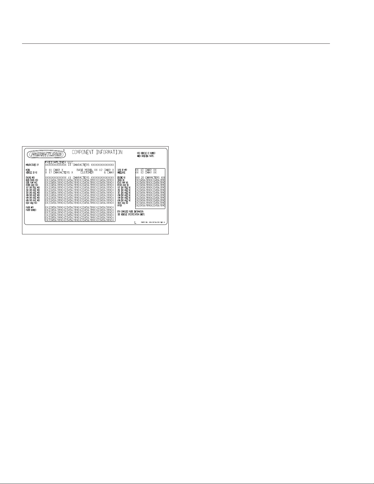
The component information label lists the vehicle
model, identification number, and major component
models. It also lists the major assemblies and installations shown on the chassis specification sheet. The
component information label is typically attached to
the passenger-side dash. An illustration of the label
is shown in
Fig. 1.1.
02/20/2012 f080176
Fig. 1.1, Component Information Label
1.1

2
Vehicle Access
Door Locks and Handles ........................................................... 2.1
Cab Access, Fixed Steps ........................................................... 2.1
Cab Access, Mobile Stairs .......................................................... 2.4
Back-of-Cab Access ............................................................... 2.7
Opening the Grille ................................................................ 2.8
Cab Tilt System .................................................................. 2.9
Vehicle Access
Door Locks and Handles
One common key operates the ignition switch and all
of the door locks.
IMPORTANT: Each key is numbered. Record
the number so a duplicate key can be made, if
needed.
To unlock the right-hand door from outside the cab,
insert the key in the lock and turn it one-quarter turn
counterclockwise. Turn the key to the original position to remove it. See
3
Fig. 2.1.
4
2
nal position to remove it. Pull out on the paddle
handle to open the door.
NOTE: The cab door locks can be operated
when the doors are open.
To lock a door from outside the cab, insert the key in
the lock and turn it opposite the unlocking direction
(counterclockwise for the left-hand door, clockwise
for the right-hand door). See
To lock a door from inside the cab, push the lock
knob down or press the automatic lock button on the
door armrest, depending on what the vehicle is
equipped with. See
inside, pull the lock knob up or press the unlock button on the door armrest, depending on what the vehicle is equipped with.
Fig. 2.2. To unlock the door from
Fig. 2.2.
Cab Access, Fixed Steps
WARNING
Wet or dirty shoes greatly increase the chance of
slipping or falling. If your shoes are wet or dirty,
be especially careful when entering or exiting the
vehicle.
Always maintain three-point contact with the vehicle when entering or exiting the cab. Threepoint contact means both feet and one hand, or
both hands and one foot.
Do not jump from the vehicle.
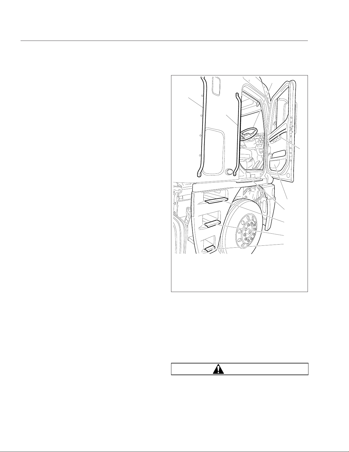
The grab handles, access steps, and steering wheel
are all part of the cab access system. Use these
"helping hands" when getting into or out of the cab to
increase your security and comfort.
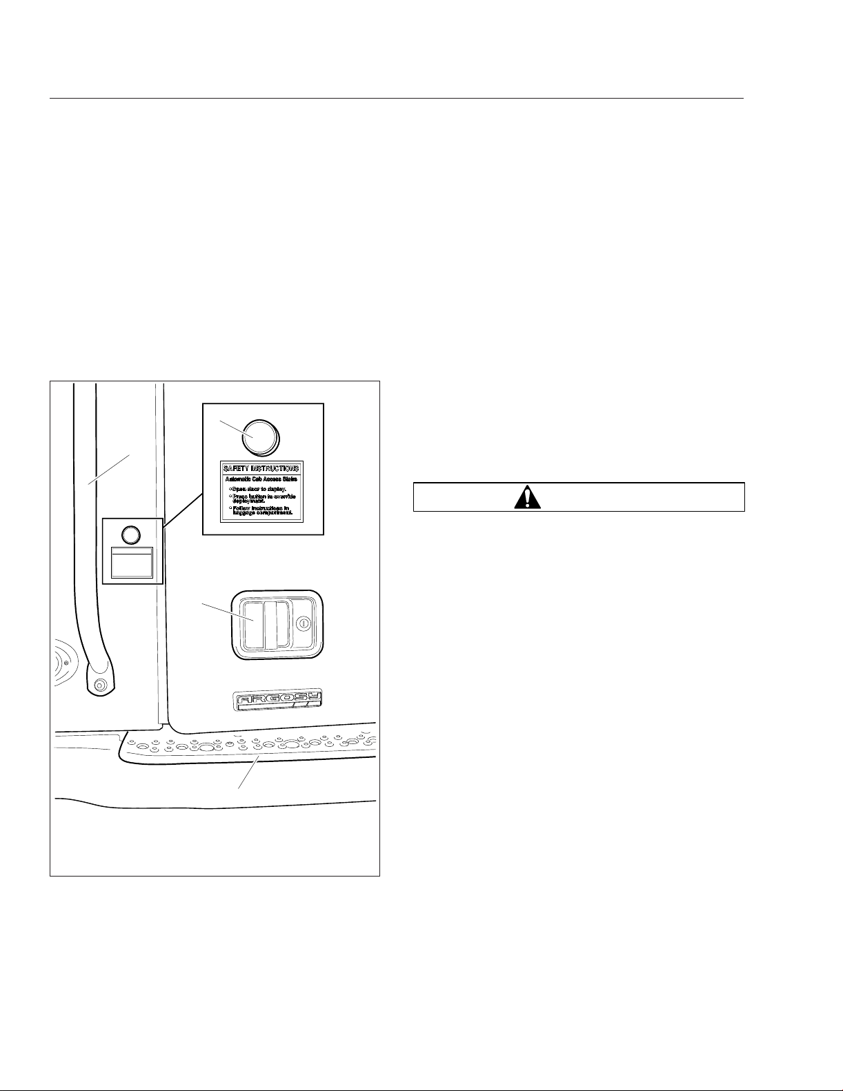
1
05/03/2012 f720751
1. Exterior Deck
2. Door Handle
3. Forward Grab Handle
Fig. 2.1, Door Exterior (right side shown)
To unlock the left-hand door from outside the cab,
insert the key in the lock and turn it one-quarter turn
clockwise. Turn the key counterclockwise to the origi-
2.1
4. Mobile Stairs Override
Button
Left Side Entry
1.
Open the left-hand door and place anything that
you are carrying in the cab.
2.
Grasp the aft grab handle with your right hand
and the forward grab handle with your left hand.
Fig. 2.3.
See
3.
Place your right foot on the bottom step and pull
yourself up.
4.
Place your left foot on the middle step, reaching
higher on both grab handles.
Vehicle Access
23
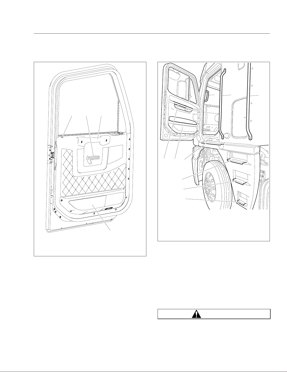
04/16/2012 f720747
1. Door Pocket
2. Lock Knob
3. Door Handle
Fig. 2.2, Door Interior
4
1
4. Upper Door Grab
Handle
4
12
04/27/2012 f720748
1. Upper Door Grab
2. Door Pocket
3. Exterior Deck
4. A-Pillar Grab Handle
Fig. 2.3, Fixed Steps and Grab Handles, Left Side (RHD
7.
Step into the cab with your right foot first.
Handle
3
7
8
9
5. Forward Grab Handle
6 Aft Grab Handle
7. Top Step
8. Middle Step
9. Bottom Step
shown)
5
6
5.
Place your right foot on the top step and pull
yourself up.
NOTE: The left side of the cab is equipped with
an A-pillar grab handle or the steering wheel,
depending on whether the vehicle is left-hand
drive (LHD) or right-hand drive (RHD).
6.
Move your right hand to the forward grab handle
and your left hand to the steering wheel or
A-pillar grab handle, then place your left foot on
the deck.
Left Side Exit
IMPORTANT: Do not attempt to exit the cab
while carrying any items in your hands.
1.
If you take items with you, place them in an accessible location on the seat or cab floor. Make
sure they will not get in your way as you exit.
WARNING
Always face in when exiting the cab. Do not attempt to exit with your back to the cab, as you
2.2
Vehicle Access
would going down a flight of stairs. It is easier to
slip or lose your balance. If you slip when exiting
in this way, there is a greater likelihood of personal injury.
NOTE: The left side of the cab is equipped with
an A-pillar grab handle or the steering wheel,
depending on whether the vehicle is LHD or
RHD.
2.
Grasp the steering wheel or A-pillar grab handle
with your left hand, place your right hand on the
forward sidewall grab handle, and place both feet
on the deck, facing into the cab.
3.
Grasp the forward grab handle with your left
hand and move your right hand to the aft grab
handle.
4.
Move your right foot to the top step.
5.
Move your left foot to the middle step and lower
your hands on both grab handles.
6.
Move your right foot to the bottom step.
7.
Step to the ground with your left foot first.
Right Side Entry
1.
Open the right-hand door and place anything that
you are carrying in the cab.
2.
Grasp the aft sidewall grab handle with your left
hand and the forward grab handle with your right
hand. See
3.
Place your left foot on the bottom step and pull
yourself up.
4.
Place your right foot on the middle step, reaching
higher on both grab handles.
5.
Place your left foot on the top step and pull yourself up.
NOTE: The right side of the cab is equipped
with an A-pillar grab handle or the steering
wheel, depending on whether the vehicle is LHD
or RHD.
6.
Move your left hand to the forward grab handle
and your right hand to the steering wheel or
A-pillar grab handle, then place your right foot on
the deck.
7.
Step into the cab with your left foot first.
Fig. 2.4.
7
9
8
6
5
4
3
2
1
05/04/2012 f720749
1. Bottom Step
2. Middle Step
3. Top Step
4. Exterior Deck
5. Door Pocket
Fig. 2.4, Fixed Steps and Grab Handles, Right Side
(RHD shown)
6 Upper Door Grab
Handle
7. Steering Wheel
8. Forward Grab Handle
9. Aft Grab Handle
Right Side Exit
IMPORTANT: Do not attempt to exit the cab
while carrying any items in your hands.
1.
If you take items with you, place them in an accessible location on the seat or cab floor. Make
sure they will not get in your way as you exit.
WARNING
Always face in when exiting the cab. Do not attempt to exit with your back to the cab, as you
would going down a flight of stairs. It is easier to
slip or lose your balance. If you slip when exiting
2.3
Vehicle Access
in this way, there is a greater likelihood of personal injury.
NOTE: The right side of the cab is equipped
with an A-pillar grab handle or the steering
wheel, depending on whether the vehicle is LHD
or RHD.
2.
Grasp the steering wheel or A-pillar grab handle
with your right hand, place your left hand on the
forward sidewall grab handle, and place both feet
on the deck, facing into the cab.
3.
Grasp the forward grab handle with your right
hand and move your left hand to the aft grab
handle.
4.
Move your left foot to the top step.
5.
Move your right foot to the middle step and lower
your hands on both grab handles.
6.
Move your left foot to the bottom step.
7.
Step to the ground with your right foot first.
Cab Access, Mobile Stairs
WARNING
•
vehicle is in motion (stairs automatically stow if
the vehicle begins to move)
•
sensors detect weight on the stairs
•
cab is tilted
•
an obstacle is encountered in the stair travel
path
•
the disable button is pressed
To prevent deployment of the stairs from outside the
vehicle, press the button on the side of the cab, directly above the stairs, before opening the door. See
Fig. 2.1.
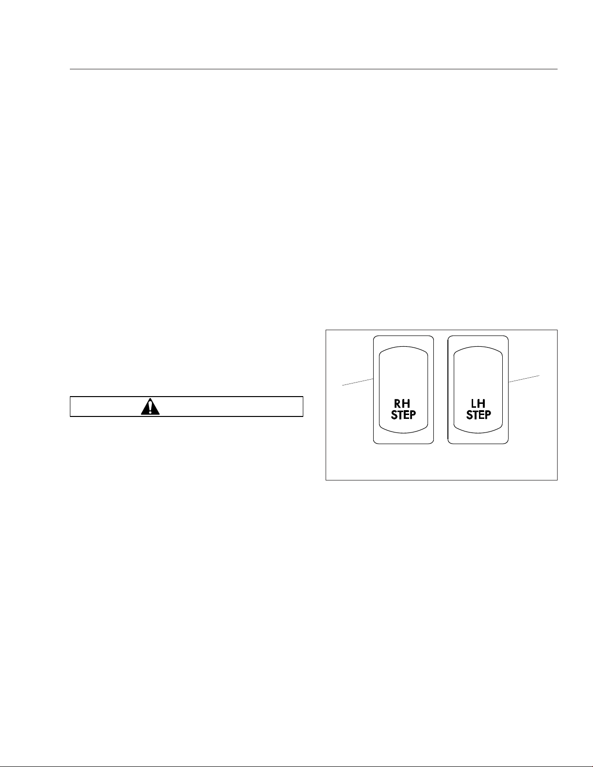
To prevent deployment of the stairs from inside the
cab, press the dash rocker switch labeled RH STEP
or LH STEP while opening the cab door. See
Fig. 2.5.
2
1
Wet or dirty shoes greatly increase the chance of
slipping or falling. If your shoes are wet or dirty,
be especially careful when entering or exiting the
vehicle.
Always maintain three-point contact with the vehicle when entering or exiting the cab. Threepoint contact means both feet and one hand, or
both hands and one foot.
Do not jump from the vehicle.
The grab handles, access steps, and steering wheel
are all part of the cab access system. Use these
"helping hands" when getting into or out of the cab.
They will increase your security and comfort.
The mobile stairs will deploy when the cab door is
opened. As the stairs deploy, an audible alert sounds
outside the vehicle. If anything prevents deployment
of the stairs, a buzzer will sound and an indicator will
illuminate on the dash.
The cab stairs will not operate under the following
conditions:
•
parking brake is not set
f61118204/24/2012
1. Right-Hand Stairs
Switch
Fig. 2.5, Mobile Stairs Deployment Switches
2. Left-Hand Stairs
Switch
NOTE: Pressing the disable button or switch will
disable the stairs for one cycle of opening and
closing the door. You must press the disable
button each time you want to prevent deployment of the stairs.
Left Side Entry
1.
Open the left-hand door and place anything that
you are carrying in the cab.
2.
Grasp the aft grab handle (Fig. 2.6) with your
right hand and grab the forward grab handle with
your left hand, reaching up as far as is
comfortable.
3.
Place your right foot on the bottom step and pull
yourself up.
2.4
Vehicle Access
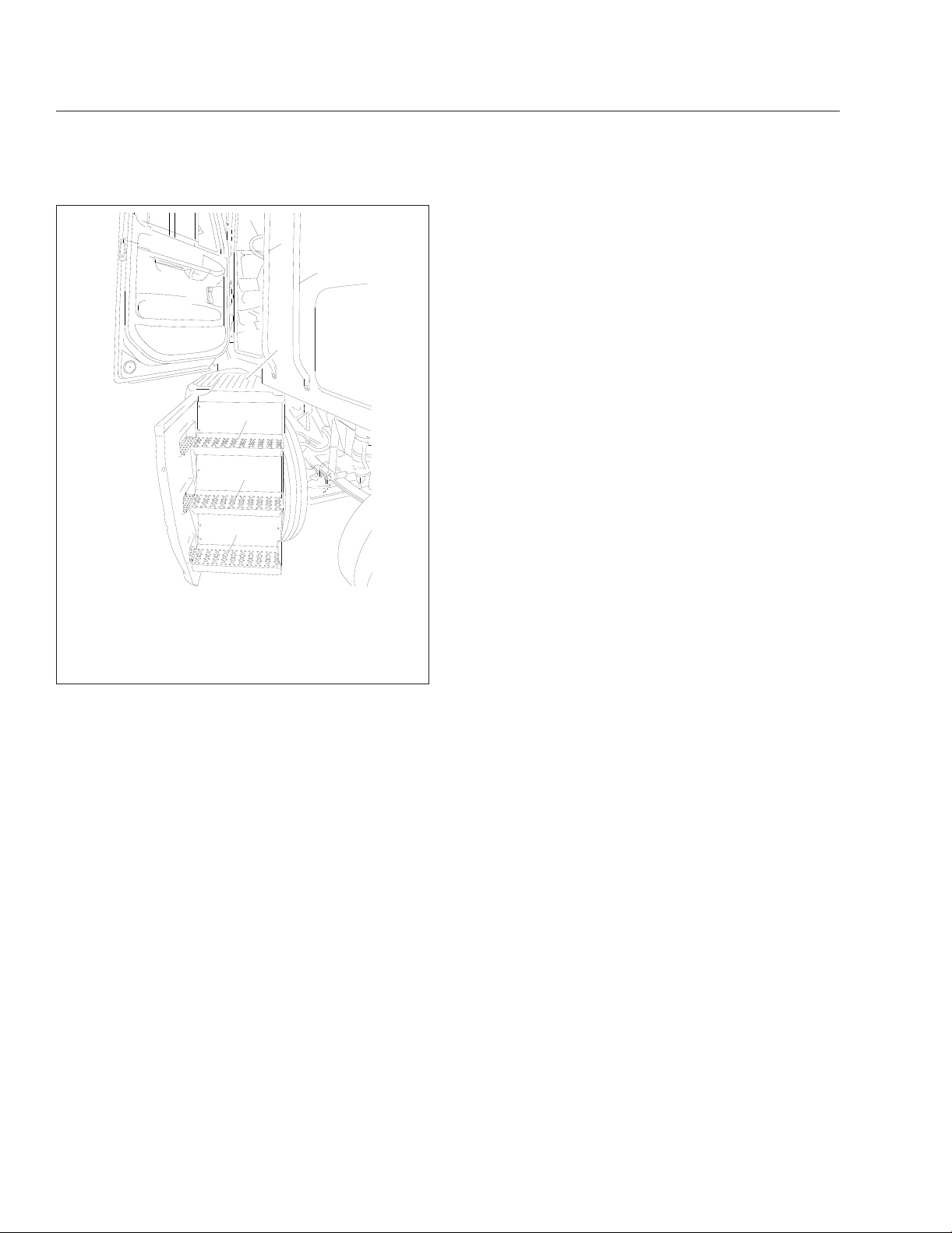
7
6
5
4
3
2
1
08/10/98
1. Bottom Step
2. Middle Step
3. Top Step
4. Top Deck
Fig. 2.6, Mobile Stairs, Left-Hand Side
4.
Place your left foot on the middle step and pull
5. Aft Grab Handle
6. Forward Grab Handle
7. Steering Wheel
f720309
yourself up.
5.
Move your left hand to the forward grab handle,
then place your left foot on the top step.
NOTE: The left side of the cab is equipped with
an A-pillar grab handle or the steering wheel,
depending on whether the vehicle is LHD or
RHD.
6.
Pull yourself up and place your right foot on the
top deck and move your left hand to the A-pillar
grab handle or steering wheel.
7.
Move your right hand to the steering wheel or
A-pillar grab handle.
8.
With both hands gripping the steering wheel or
A-pillar grab handle, move your right foot into the
cab.
Left Side Exit
IMPORTANT: Do not attempt to exit the cab
while carrying any items in your hands.
NOTE: The left side of the cab is equipped with
an A-pillar grab handle or the steering wheel,
depending on whether the vehicle is LHD or
RHD.
1.
Grasp the steering wheel or A-pillar grab handle
with both hands, and stand on the deck at the
top of the stairs facing into the cab.
2.
With your right hand, grasp the forward grab
handle.
3.
Move your right foot to the top step.
4.
Move your left hand to the forward grab handle
and move your left foot to the middle step.
5.
Move your right hand to the aft grab handle and
move your right foot to the bottom step.
6.
Step to the ground with your left foot.
Right Side Entry
1.
Open the right-hand door and place anything that
you are carrying in the cab.
2.
Grasp the aft grab handle with your left hand and
grab the forward grab handle with your right
hand, reaching up as far as you’re comfortable.
Fig. 2.7.
See
3.
Place your left foot on the bottom step and pull
yourself up.
4.
Place your right foot on the middle step and pull
yourself up.
5.
Move your right hand to the forward grab handle,
then place your right foot on the top step.
NOTE: The right side of the cab is equipped
with an A-pillar grab handle or the steering
wheel, depending on whether the vehicle is LHD
or RHD.
6.
Pull yourself up and place your left foot on the
top deck and move your right hand to the A-pillar
grab handle or steering wheel.
7.
Move your left hand to the steering wheel or
A-pillar grab handle.
2.5
Vehicle Access
NOTE: The right side of the cab is equipped
with an A-pillar grab handle or the steering
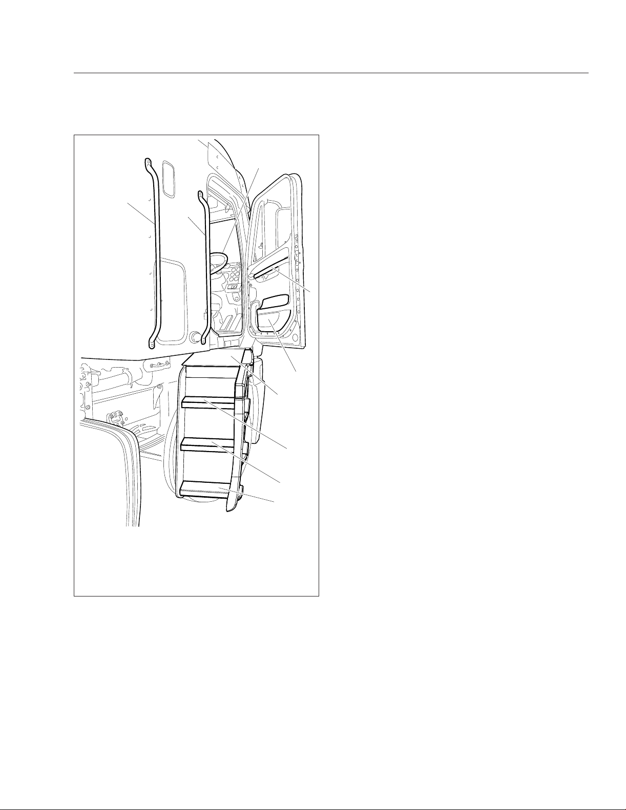
7
9
8
6
5
wheel, depending on whether the vehicle is LHD
or RHD.
1.
Grasp the steering wheel or A-pillar grab handle
with both hands, and stand on the deck at the
top of the stairs facing into the cab.
2.
With your left hand, grasp the forward grab
handle.
3.
Move your left foot to the top step.
4.
Move your right hand to the forward grab handle
and move your right foot to the middle step.
5.
Move your left hand to the aft grab handle and
move your left foot to the bottom step.
6.
Step to the ground with your right foot.
Mobile Stair Lock-Up Procedures
Access Stairs Will Not Fully Deploy
4
3
2
1
05/16/2012 f720750
1. Bottom Step
2. Middle Step
3. Top Step
4. Exterior Deck
5. Door Pocket
Fig. 2.7, Mobile Stairs and Grab Handles, Right-Hand
8.
With both hands gripping the steering wheel or
Side (RHD shown)
6 Upper Door Grab
Handle
7. Steering Wheel
8. Forward Grab Handle
9. Aft Grab Handle
A-pillar grab handle, move your left foot into the
cab.
Right Side Exit
IMPORTANT: Do not attempt to exit the cab
while carrying any items in your hands.
1.
Close the cab door.
2.
Ensure the parking brake is set.
3.
Inspect for an obstruction in the travel path of the
steps.
4.
Start the engine to increase battery voltage.
5.
If the vehicle is parked at an incline greater than
3.5 degrees in any direction, move it to a level
surface (if conditions permit).
6.
Open the door again. If the steps will not fully
deploy, but will return to a fully stowed position,
press the RH STEP or LH STEP switch while
opening the cab door.
7.
Enter and exit the cab using the access instructions for fixed steps.
Access Stairs Will Not Fully Stow
1.
Open and close the door.
2.
Inspect for an obstruction in the travel path of the
steps.
3.
Start the engine to increase battery voltage.
4.
If the vehicle is parked at an incline greater than
3.5 degrees in any direction, move it to a level
surface (if conditions permit).
2.6
Vehicle Access
5.
Open and close the door again. If the steps still
will not stow, leave the door open and exit the
cab from the opposite side.
6.
Place a hand on the exterior surface of the step,
then apply light pressure to the step while closing the door.
7.
If the step stows, press the yellow disable button
next to the grab handle. This will disable the step
for cycle of opening and closing the door.
8.
If the steps will not fully stow, follow the instructions on the inside of the baggage door to safely
stow the steps.
4
6
5
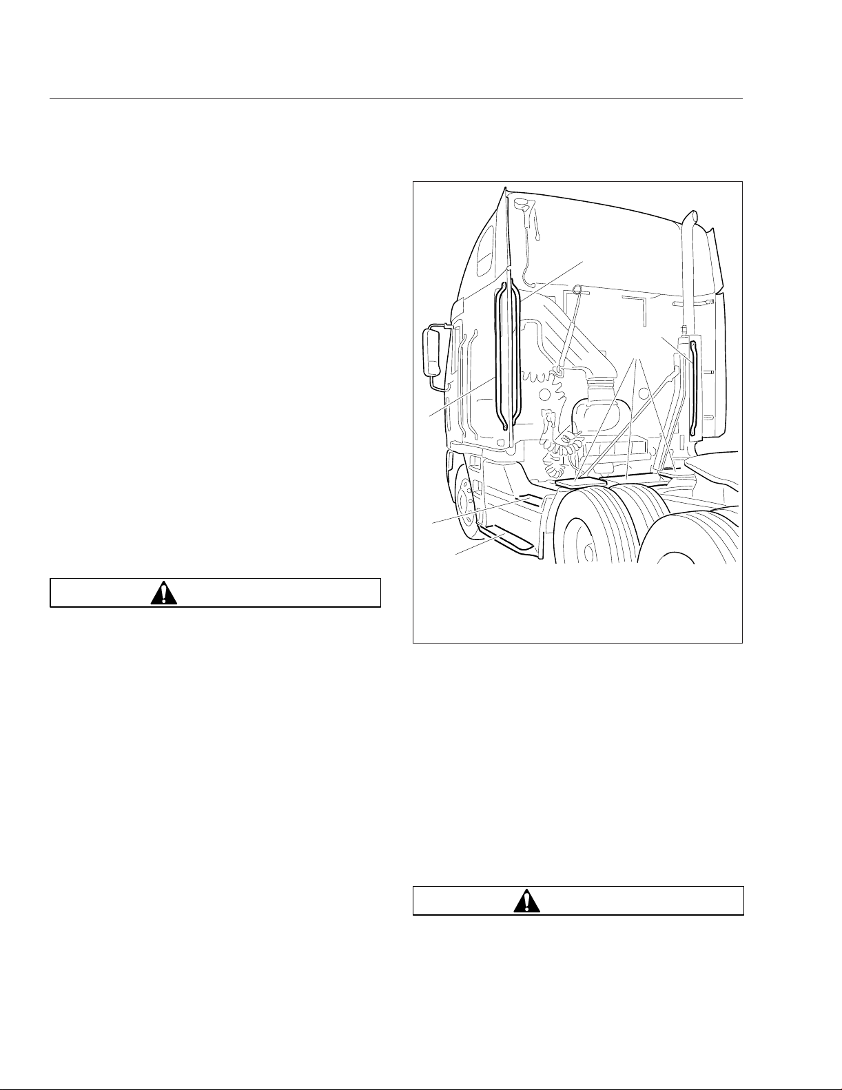
Back-of-Cab Access
Grab handles are typically located on the backwall of
the cab or sleeper, or on the inside of the cab extender, if equipped. See
also be provided on the exhaust stack. Steps may be
mounted on the fuel tank(s), battery or tool box(es),
or on metal brackets secured to the frame rail. A
deck plate is mounted across the top of the frame
rails. All other areas are not meant to support backof-cab access.
Follow these rules for back-of-cab access. Failing
to follow these rules could lead to a fall, and possible personal injury.
Never step on any exterior part unless it has a
slip-resistant surface meant for safe stepping. If
the surface is movable, such as a battery box
cover with a slip-resistant surface, be certain it is
firmly secured.
Be careful not to trip on items such as chains or
air lines in the back-of-cab area.
Always follow safety procedures for back-of-cab
access, maintaining three-point contact—both
hands and one foot, or both feet and one hand—
whenever moving around, and always face in toward the deck plate when climbing up or down.
Wet or dirty shoes, steps, or grab rails greatly
increase the chance of slipping or falling. If your
shoes or the contact areas are wet or dirty, clean
and dry them as much as possible before accessing the back of cab area, and be especially
careful when climbing or standing on the vehicle.
Fig. 2.8. A grab handle may
WARNING
3
2
1
05/09/2012 f720752
1. Bottom Step
2. Top Step
3. Outboard Grab
Handle
Fig. 2.8, Back-of-Cab Access
Never jump onto, or off of, a vehicle; doing so
creates a very high likelihood of a fall and personal injury.
Wet or dirty shoe soles greatly increase the chance
of slipping or falling. If your soles are wet or dirty, be
especially careful when accessing the back-of-cab
area.
Be careful not to get hands or feet tangled in hoses
or other back-of-cab equipment. Carelessness could
cause a person to trip and fall, with possible injury.
4. Inboard Grab Handle
5. Deck Plates
6. Exhaust-Mounted
Grab Handle
Accessing Back-of-Cab Area
WARNING
External surfaces of the exhaust system remain
hot after the engine has been shut down. When
accessing the back of the cab or sleeper, do not
2.7
touch any part of the exhaust system other than
the exhaust-mounted grab handle, if equipped, or
severe burns could occur.
1.
Facing the center of the deck plate, grasp the
grab handle with both hands. Reach up as far as
is comfortable.
2.
Place one foot on the bottom step and pull yourself up.
3.
Place your other foot on the top step.
4.
Move your lower hand to a higher position on the
grab handle.
5.
Step onto the deck plate.
Exiting the Back-of-Cab Area
1.
Face the center of the vehicle and grasp the
grab handle with both hands.
2.
Place one foot at a time on the top step.
3.
Move your upper hand to a lower position on the
grab handle.
4.
Move one foot to the bottom step.
5.
Step to the ground with your upper foot first.
Vehicle Access
05/23/2011 f602457
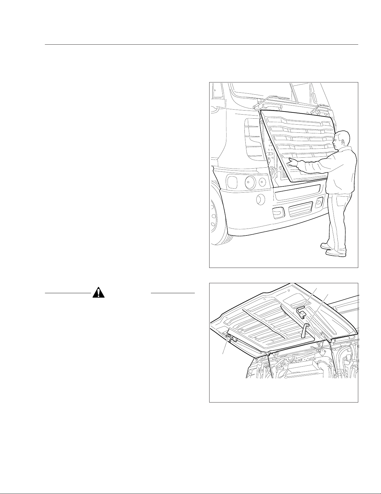
Opening the Grille
CAUTION
Step back from the grille when opening it. The
grille can open quickly and could hit a person,
possibly resulting in personal injury.
Opening the grille allows the driver access to the engine oil dipstick, the coolant fill cap, and the windshield washer reservoir. To open the grille, face the
front of the truck, reach through the latch access
openings on either side of the grille, and release the
two latches. See
both hands and lift. Pull the interior straps down to
pull the grille shut. See
Make sure the grille is shut and latched securely.
NOTE: On some vehicles, the access latches
are located behind the lower corners of the
grille.
Fig. 2.9. Grip the grille firmly with
Fig. 2.10.
Fig. 2.9, Opening the Grille
1
A
1
05/23/2011 f602458
A. Use this strap to close the grille.
1. Grille Latches
Fig. 2.10, Grille (shown fully open)
2.8
Vehicle Access
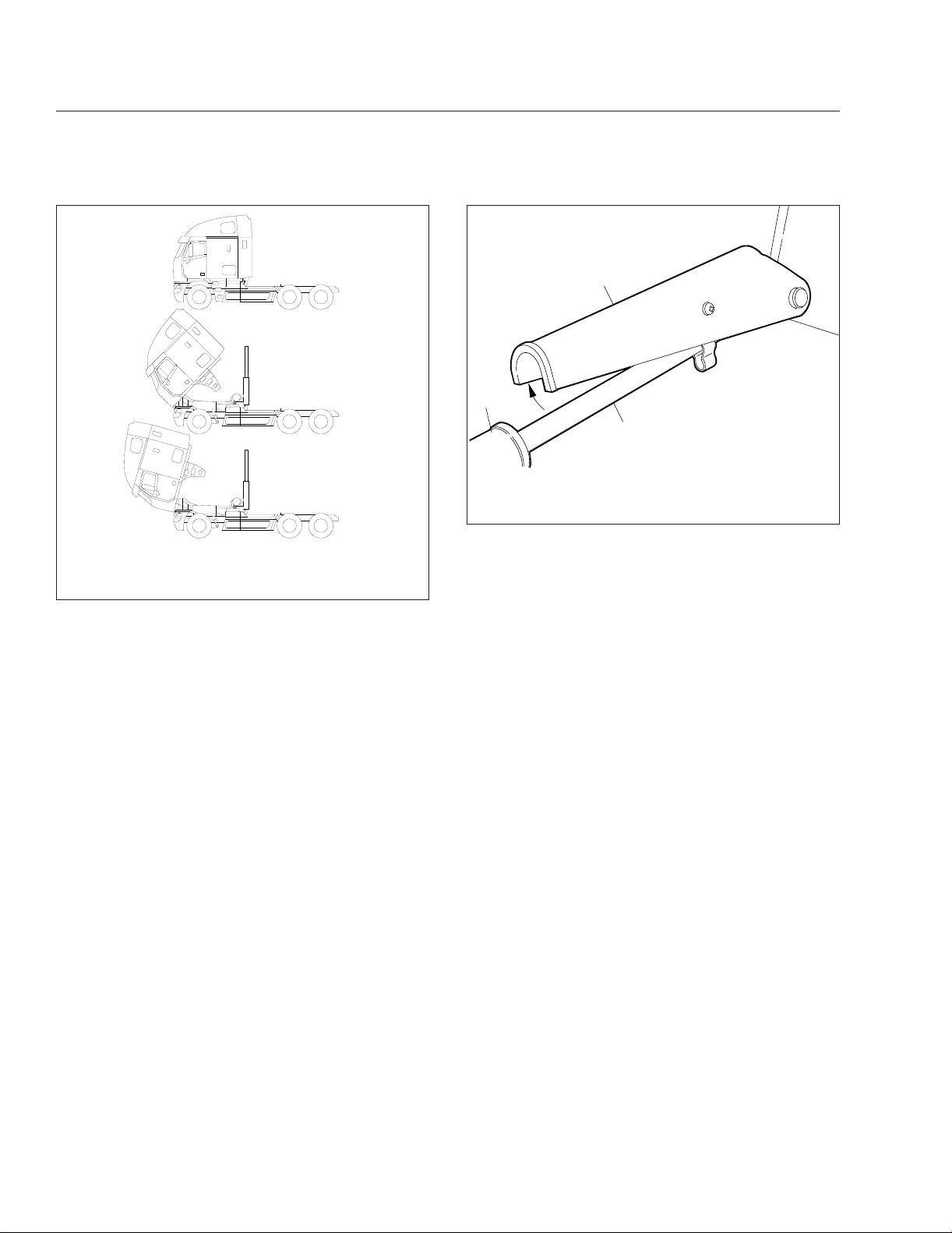
Cab Tilt System
The hydraulic tilt system is used to tilt and lower the
cab. An electric motor is used to activate the hydraulic tilt pump. The tilt pump can also be operated
manually if necessary. A pump handle is located in
the baggage compartment for manually working the
tilt pump.
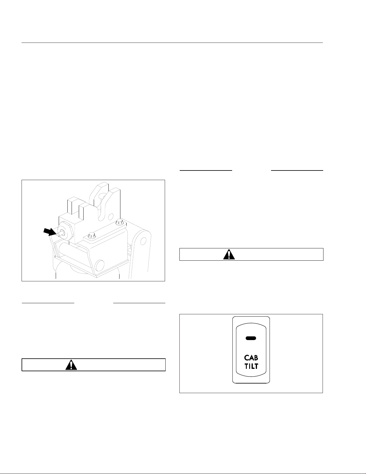
The hydraulic cab latches open automatically when
the cab is tilted. When the cab is returned to the operating position, the latch hooks lock automatically.
An indicator pin on the outboard side of each latch
protrudes when the latch is unlocked, and recedes
when the latch is locked. See
Fig. 2.11.
ing an accident that could result in personal injury or property damage.
The hydraulic tilt system is a cab-tilting, not a
cab-holding device. Do not leave the vehicle unattended unless the cab is fully tilted or resting
against the safety stop. Holding the cab in place
with the hydraulic tilt system may result in personal injury or death and/or property damage.
IMPORTANT: Before tilting or lowering the cab,
read the warning label on the tilt pump and the
tilt instructions label on the exhaust stack.
NOTICE
Before tilting the cab, make sure the vehicle is
parked on level ground, both side-to-side and
fore-to-aft. Tilting the cab while the vehicle is
parked on a slope may damage the cab mounts
and prevent you from returning the cab to the
operating position.
1.
Park the vehicle on a level surface, place the
vehicle in neutral, shut down the engine, and set
the parking brake. Chock the tires.
10/19/94
Fig. 2.11, Indicator Pin
f310441
NOTICE
Do not use either the telescoping tube assembly
or the hydraulic tilt cylinder as a step or handhold; you could damage the transmission, telescoping tube assembly, or the tilt cylinder.
Tilting the Cab
WARNING
Before tilting the cab, make sure there is adequate clearance in front of the vehicle and that
the area is free of people and objects.
Do not tilt the cab with the engine running. Tilting the cab could engage the transmission. If the
engine is running, the vehicle could move, caus-
WARNING
Objects falling in the cab or a door flying open
could damage the vehicle or cause personal injury.
2.
Secure all loose articles in the cab and bunk,
then activate the tilt system power switch on the
dash. See
3.
Exit the cab and make sure the doors are fully
latched.
Fig. 2.12.
f61117904/24/2012
Fig. 2.12, Cab Tilt Switch
2.9
NOTICE
Make sure the grille is open before tilting the cab
(vehicles built from June 2011). Leaving the grille
closed while tilting the vehicle will cause damage
to the grille.
IMPORTANT: Vehicles built February 2012 and
later are equipped with a safety mechanism that
prevents the tilt pump from operating when the
grille is not open.
4.
Fully open the grille.
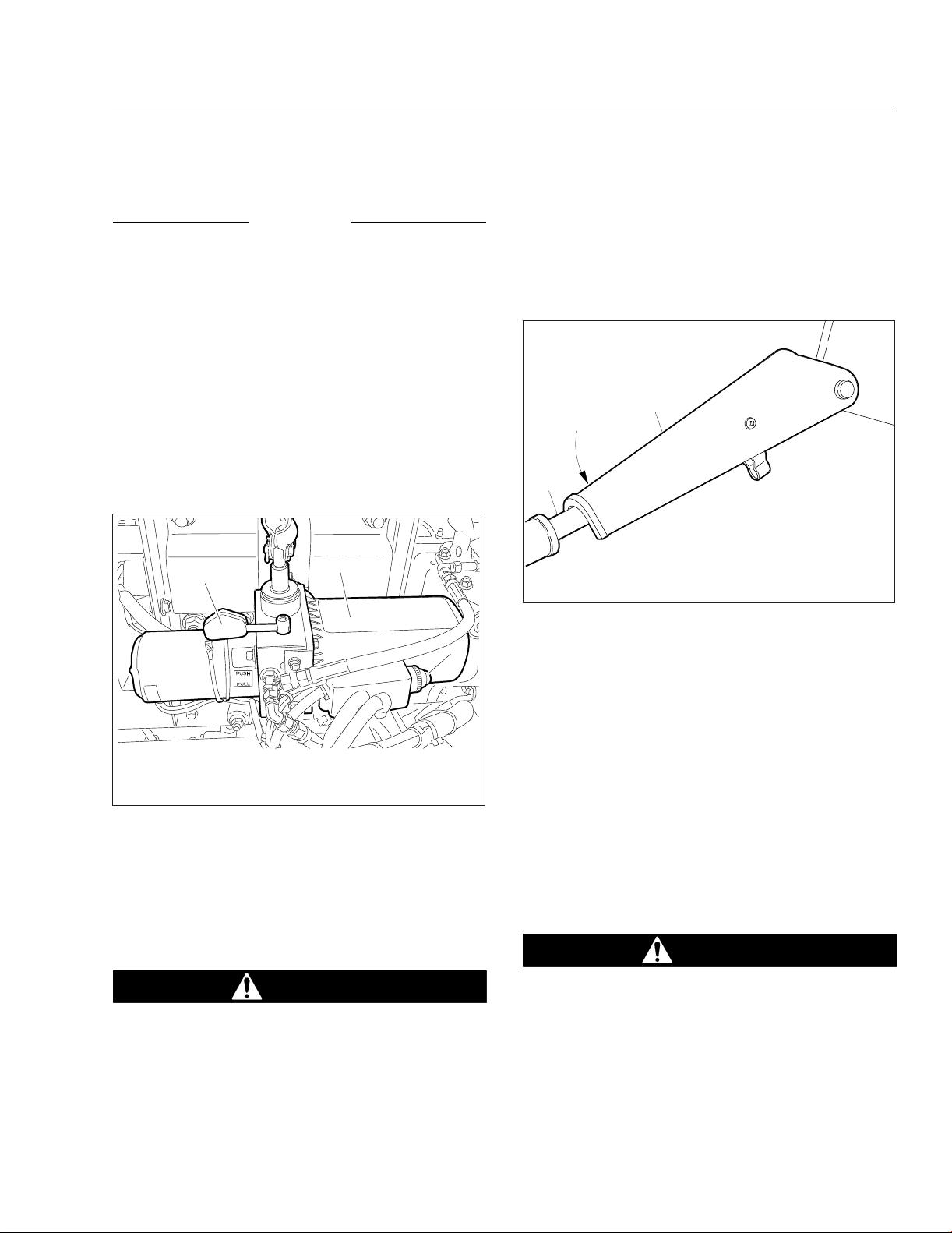
5.
Check the cab travel path for obstructions.
6.
Move the pump control lever to the TILT position.
Fig. 2.13.
See
Vehicle Access
8.
When the cab reaches a 30-degree angle, stop
tilting the cab by letting go of the pump button.
Engage the safety stop on the right tilt cylinder
rod. See
cab from accidentally dropping below this
position.
1
Fig. 2.14. The safety stop prevents the
2
1
05/07/2012 f602470
1. Pump Control Lever
2. Hydraulic Tilt Pump
Fig. 2.13, Cab Tilt Pump
7.
Press and hold the button on the pump to disengage the hold-down latches and begin tilting the
cab.
2
3
3. Pump Activation
Button
IMPORTANT: Check the indicator pin on each
cab latch. The latches have disengaged if the
pins are out. See
Fig. 2.11.
DANGER
Make sure the safety stop is engaged on the right
tilt cylinder rod. If the safety stop isn’t engaged,
and the cab should drop, the result could be serious injury or death.
04/15/93
1. Tilt Cylinder Rod 2. Safety Stop
Fig. 2.14, Safety Stop Engaged
9.
To tilt the cab all the way, press and hold the
button on the pump until the cab nears a 45degree angle (the balance point). See
Once the cab goes beyond 45 degrees, release
the button on the pump and move the tilt pump
lever to the RETURN position in order to slow
cab descent.
f310357a
Fig. 2.15.
IMPORTANT: If the cab stops after it has gone
beyond 45 degrees, don’t force it down with the
tilt pump. The velocity fuses have locked the tilt
cylinders. To unlock them, see Hydraulic
Lockup, below.
Returning the Cab to Operating
Position
DANGER
Stay completely clear of the cab’s travel path at
all times. Once the safety stop has been released, don’t lean over the frame rails, the engine, or the transmission for any reason. To do
so could result in serious injury or death.
1.
Move the pump lever to the RETURN position.
2.10
Vehicle Access
A
B
C
03/27/98
A. Upright or Operating Position
B. 45° Tilted Position (balance position)
C. Full-Tilt Position
Fig. 2.15, Cab Tilt Positions
2.
Check the cab travel path for obstructions.
3.
Press and hold the button on the pump to begin
f000896
moving the cab to the operating position.
NOTE: To slow the cab descent, reverse the tilt
pump lever after the cab passes the balance
point.
4.
Allow the cab to lower to the safety stop, then
move the safety stop away from the right tilt cylinder rod. See
5.
Press and hold the button on the pump until the
Fig. 2.16.
cab nears a 45-degree angle (the balance point).
Fig. 2.15. Once the cab goes beyond 45
See
degrees, release the button on the pump and
move the tilt pump lever to the TILT position in
order to slow cab descent.
IMPORTANT: If the cab stops after it has gone
beyond 45 degrees, don’t force it down with the
tilt pump. The safety stop is in the locked position or, the velocity fuses have locked the tilt
cylinders. Release the safety stop or, to unlock
the fuses, see Hydraulic Lockup, below.
6.
Move the pump lever to the RETURN position.
1
3
2
04/15/93
1. Safety Stop
2. Tilt Cylinder Rod
Fig. 2.16, Safety Stop Disengaged
7.
Check the indicator pin on each cab latch. The
3. Tilt Cylinder
f310358a
latches are locked when the pins have moved
back into the piston and cylinder spring assembly.
NOTE: Maintain the hydraulic oil level at the oil
fill plug. Add oil only when the cab is in the operating position. Use only Freightliner-approved
hydraulic oil. See Group 60 of the Century
Class Trucks Maintenance Manual.
8.
Close the grille.
9.
Switch off the tilt system dash switch.
Hydraulic Lockup
Hydraulic lockup can occur for the following reasons:
•
very cold temperatures
•
use of the wrong hydraulic fluid
•
air in the system
•
sudden cab movement
•
ruptured hydraulic line
•
continued pumping after the cab goes overcenter
•
tilt strut in locked position while lowering the
cab
2.11

Any of the above situations will lock the tilt cylinders.
To unlock the cylinders, the cab must be moved in
the opposite direction of travel.
For example, if the cab is moving toward the full-tilt
position when the lockup occurs, move the control
lever to RETURN and work the pump a few strokes
to unlock the cylinders. Move the control lever to the
TILT position and allow the cab to descend to a fulltilt position.
If the cab is moving toward the lowered (operating)
position when the lockup occurs, move the control
lever to TILT and work the pump a few strokes to
unlock the cylinders. Move the control lever to RETURN and allow the cab to descend to the operating
position.
Vehicle Access
2.12

3
Electrical System
Circuit Breaker/Relay Panel ......................................................... 3.1
Low Voltage Disconnect Feature ..................................................... 3.1
Cab Load Disconnect Switch ........................................................ 3.1
Battery Access ................................................................... 3.1
Electrical System
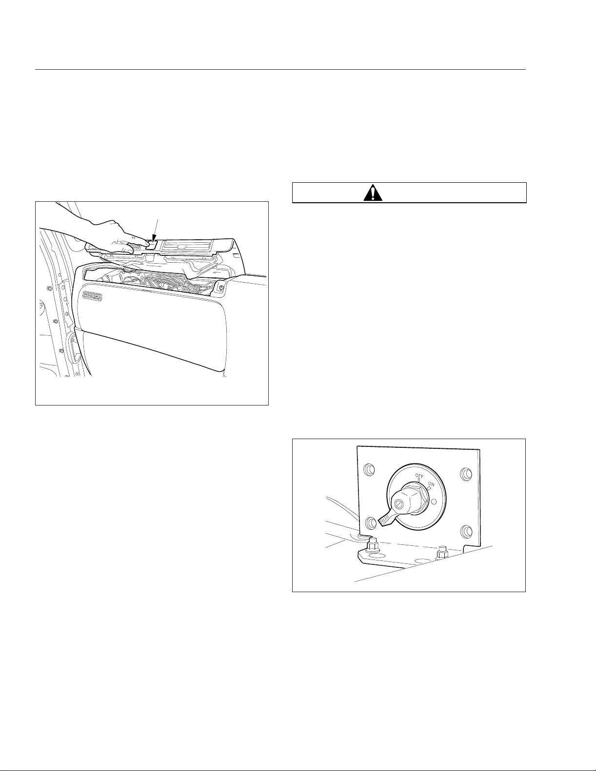
Circuit Breaker/Relay Panel
The circuit breaker/relay panel is located in the dash
in front of the passenger seat. To access the compartment, press the button labeled PRESS and lift
the top dash panel. See
05/07/2012 f545897
A. Press the button and lift the top dash panel
Fig. 3.1, Circuit Breaker/Relay Panel (right-hand drive
Fig. 3.1.
A
shown)
Another sticker is located inside the right-hand door
frame behind the seat, along with the LVD module.
Cab Load Disconnect Switch
WARNING
Turning the cab load disconnect switch (CLDS) to
the off position does not disconnect the connection between the battery and the starter. To work
on the vehicle safely, the negative leads must be
disconnected from the battery.
IMPORTANT: The ignition should be turned off
before turning the CLDS to on or off.
The CLDS is used to avoid excessive draw on the
battery when the vehicle is parked for an extended
period of time by disconnecting (or opening) the connection between the battery and the most of the vehicle electrical system. See
The CLDS may be mounted:
•
inside the cab on the outboard side of the
driver’s seat;
•
at the battery box;
•
outboard on the left frame rail.
Fig. 3.2.
Low Voltage Disconnect
Feature
The low voltage disconnect (LVD) feature protects
the batteries from excessive discharge by disconnecting certain circuits from battery power supply.
This allows the batteries to maintain acceptable
charge to restart the vehicle. The LVD system turns
off cab and sleeper accessories when voltage drops
to 12.3 volts. An alarm sounds for one minute before
accessories are turned off. If no action is taken within
that minute, the LVD module will shut off power to
predetermined cab and sleeper circuits and illuminate
an LED indicator on the LVD module located inside
the right-hand door frame behind the seat. These
circuits will remain off until the LVD measures 13.0
volts on the electrical system, which can be done by
starting the engine. After the engine is started, the
system will reset.
All vehicles equipped with LVD should have a sticker
on the dash indicating the presence of the system.
06/19/2007 f545071
Fig. 3.2, Cab Load Disconnect Switch
Battery Access
NOTE: On vehicles with vertically-mounted mufflers, tilt the cab slightly to open the battery box.
3.1

The batteries are typically located aft wall of the cab/
sleeper compartment. To remove the cover from the
battery box, release the latch and lift the cover.
Electrical System
3.2

4
Instruments
Instrumentation Control Units ....................................................... 4.1
Warning and Indicator Lights ........................................................ 4.3
Instruments ...................................................................... 4.7
Driver Message Center ........................................................... 4.10
Overhead Instrument Panel ........................................................ 4.19
Instruments
Instrumentation Control Units
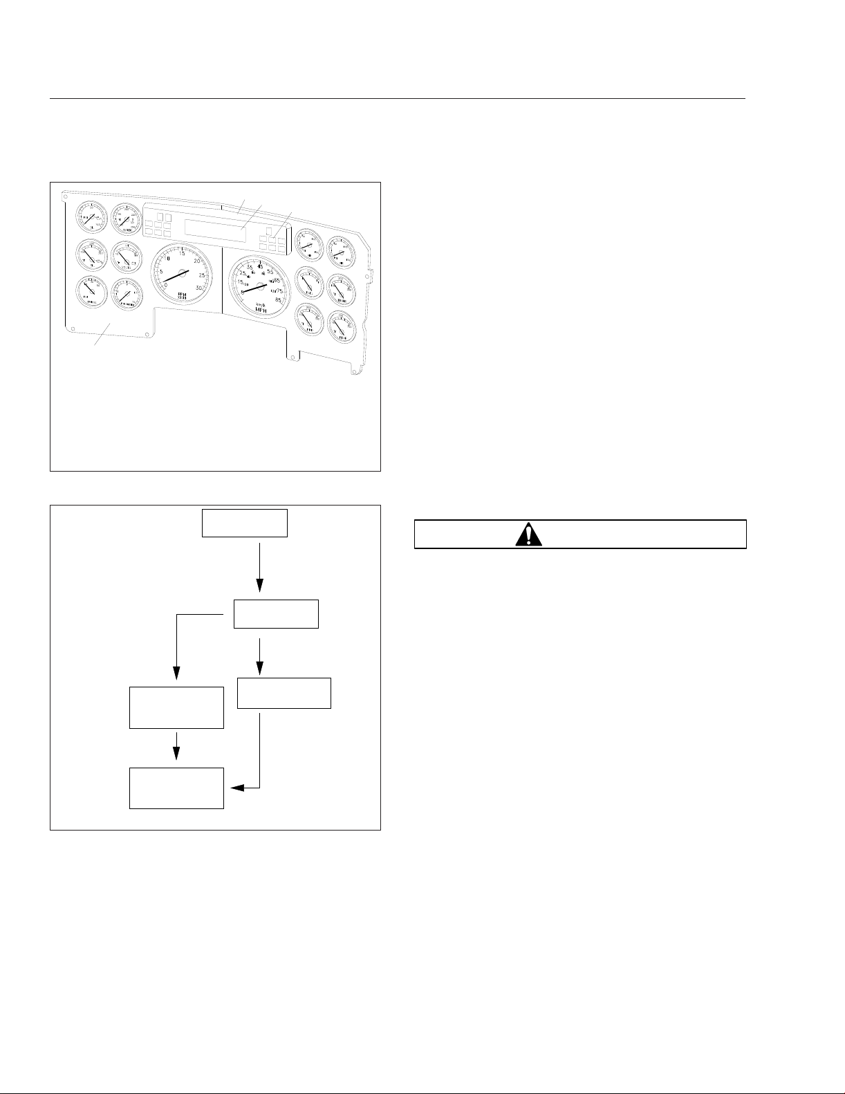
The instrumentation control unit (ICU) provides the
driver with engine and vehicle information. It is comprised of standard and optional gauges, an audible
warning, a driver message center, and a lightbar containing warning and indicator lamps (also known as
telltales). Warning and indicator lamps illuminate in
red (danger), amber (caution), green (status advisory), or blue (high-beam headlights activated).
Argosy vehicles are equipped with either an ICU4M
Fig. 4.1), ICU3 (Fig. 4.2), or ICU2M (Fig. 4.3).
(
The following headings in this chapter provide additional information and operating instructions for ICU
components:
•
"Warning and Indicator Lights"
•
"Instruments"
•
"Driver Message Center"
8
40
PSI
0
100
OIL
12
200
F
100
300
OIL
3
40
PSI
0
80
TURBO
56
200
150
F
100
250
WATER
12
8
16
VOLTS
4
90
F
10
30
150
PYRO
STOPCHECK
15
RPM
10
X 100
5
0
9
Ignition Sequence
When the ignition is turned on, the ICU runs a selfcheck. See
is a good way to ensure the ICU is functioning
properly.
IMPORTANT: Do not crank the engine until the
ICU gauge sweep is complete.
NOTE: Air gauges do not complete a sweep of
their dials during the ignition sequence.
When the ignition is turned on, the following actions
should occur:
•
•
7
FASTEN SEATBELTS
0000432 MILES
20
25
30
15
10
Fig. 4.4. Observing the ignition sequence
electronic gauges complete a full sweep of
their dials
some warning and indicator lamps illuminate,
then are extinguished
8
25
OPT OPT OPT OPTOPT OPT OPT OPT
BRAKE
45
35
70
50
30
10
5
MPH
OPT
ABS
ABS
IDLE
!
55
65
90
110
75
130
85
km/h
15
10060
PSI
P
0 160
AIR
11 12
1/2
EF
FUEL
13
F
100
14
200
300
AXLE
16
PSI
0 160
190
F
110
F
100
TRANS
200
AXLE
10060
S
AIR
270
350
300
09/29/2010 f610706b
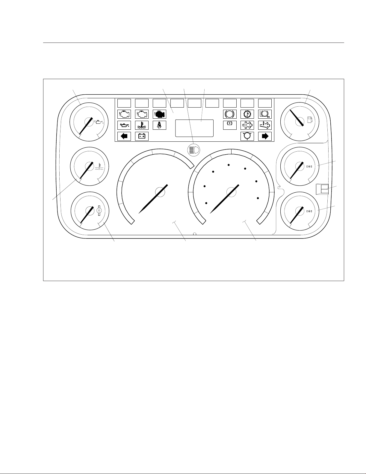
1. Engine Oil Pressure Gauge
2. Engine Coolant Temperature Gauge
3. Engine Oil Temperature Gauge
4. Battery Voltage Gauge
5. Turbo Boost Air Pressure Gauge
6. Pyrometer
7. Driver Message Center
8. Warning and Indicator Lights
9. Tachometer
10. Speedometer
11. Primary Air Pressure Gauge
12. Secondary Air Pressure Gauge
13. Fuel Level Gauge
14. Transmission Fluid Temperature Gauge
15. Forward Drive Axle Temperature Gauge
16. Rearmost Drive Axle Temperature Gauge
Fig. 4.1, ICU4M Instrument Cluster (typical)
4.1
Instruments
124 5
12
10/26/2006
PSI
150
0
F°
100
F°
100
50
100
OIL
200
250
WATER
225
350
TRANS
CHECK
11
1. Engine Oil Pressure Gauge
2. Lightbar
3. Headlight High-Beam Indicator
4. Driver Message Center
5. Fuel Level Gauge
10
5
3
STOP
20
25
15
30
25
15
5
RPM
0
X100
10
6. Primary Air Pressure Gauge
7. Mode/Reset Switch
8. Secondary Air Pressure Gauge
9. Speedometer
30
35
10
50
ABS
BRAKE
45
70
km/h
MPH
OPT
OPTOPTOPTOPTOPTOPTOPTOPT
1/2
E
F
FUEL
50
100
PSI
150
0
AIR
90
ABS
55
65
110
75
130
85
9
10. Tachometer
11. Tranismission Fluid Temperature
Gauge
12. Coolant Temperature Gauge
50
100
PSI
150
0
AIR
PUSH−
MODE
HOLD−
RESET
f610837b
6
7
8
Fig. 4.2, ICU3 Instrument Cluster
•
audible alert sounds until sufficient air pressure
builds up in the primary and secondary air systems
•
software revision level of the ICU is displayed
on the driver message center, followed by any
active faults
IMPORTANT: If any red or amber warning or
indicator lamps do not illuminate during the ICU
self-check or do not extinguish after the selfcheck completes, take the action outlined in
Table 4.1, or take the vehicle to an authorized
Daimler Trucks service facility as soon as possible.
NOTE: If active faults are present, take the vehicle to an authorized Daimler Trucks service
facility as soon as possible.
If the ICU receives active fault codes, it displays
them one after the other until the parking brake is
released or the ignition is turned off. Once the parking brake is completely released, the ICU displays
the odometer. If there are no active faults, the ICU
displays the odometer after the self-check completes.
When the self-check is complete on an ICU4M, the
fasten seat belt screen displays if the engine is off. If
the engine is running, the idle hours screen displays.
Audible Alerts
An audible alert sounds during the ignition sequence
and whenever one of the following conditions exists:
•
Engine oil pressure falls below the minimum
preset value.
•
Coolant temperature rises above the maximum
preset value.
4.2
Instruments
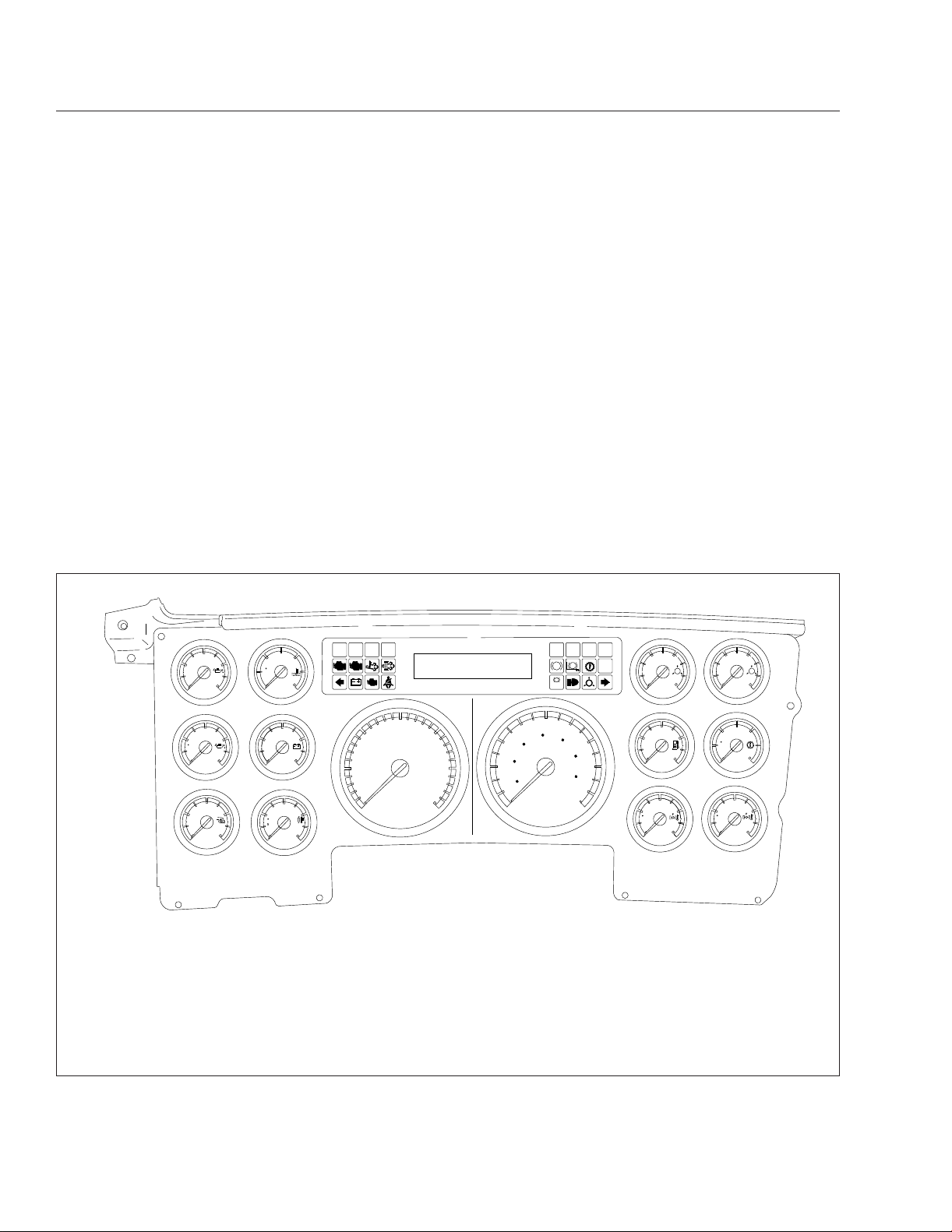
2
1
09/27/95
1. Main Dash Panel
2. Lightbar
3. Driver Message Center
4. Warning and Indicator Lights
Fig. 4.3, ICU2M Instrument Cluster (typical)
IGNITION SWITCH
TURNED TO ON
•
3
4
Door is open or the headlights are on, with the
parking brake off.
Warning and Indicator Lights
The ICU lightbar has three or four rows of warning
and indicator lights with icon symbols, depending on
the ICU. The positions of the lights may vary for the
different ICU’s, but the telltales are standard for all
Table 4.1 for a listing of standard
WARNING
f600991
applications. See
and commonly used warning and indicator lamps.
Warning and indicator lamps illuminate in red (danger), amber (caution), green (status advisory), or
blue (high-beam headlights active).
IMPORTANT: Depending upon local jurisdictional emissions guidelines, vehicles may not be
equipped with all of the lamps shown in
Table 4.1.
Engine Protection System
ICU PERFORMS
SELF−TEST
IF NO FAULTS
WERE DETECTED
123456.7
MI
12.3 VOLTS
PARKING BRAKE
RELEASED
123456.7
MI
12.3 VOLTS
01/18/2012 f040420c
Fig. 4.4, ICU Self-Check
•
Air pressure falls below approximately 70 psi
IF FAULT DETECTED
APU 190
PARKING BRAKE
RELEASED
(483 kPa).
•
Parking brake is set with the vehicle moving
faster than two miles per hour.
•
System voltage falls below 12 volts.
When the red STOP engine lamp illuminates,
most engines are programmed to shut down automatically within 30 seconds. The driver must
immediately move the vehicle to a safe location
at the side of the road to prevent causing a hazardous situation that could cause bodily injury,
property damage, or severe damage to the engine.
Fig. 4.5 for an explanation of the aftertreatment
See
system (ATS) warning indicators, and actions required to avoid further engine protection steps.
The STOP engine lamp illuminates when the engine
protection system is activated in one of two ways. On
some engines, the engine protection system will derate the engine, allowing it to run at lower rpm and
slower vehicle speed. Drive the vehicle to a safe location or to a service facility.
IMPORTANT: Safely bring the vehicle to a stop
on the side of the road and shut down the engine as soon as the red light is seen. If the engine shuts down while the vehicle is in a hazardous location, turn the key to the OFF position
for a few seconds, then restart the engine and
move the vehicle to a safer location.
4.3
STOP
STOP Engine
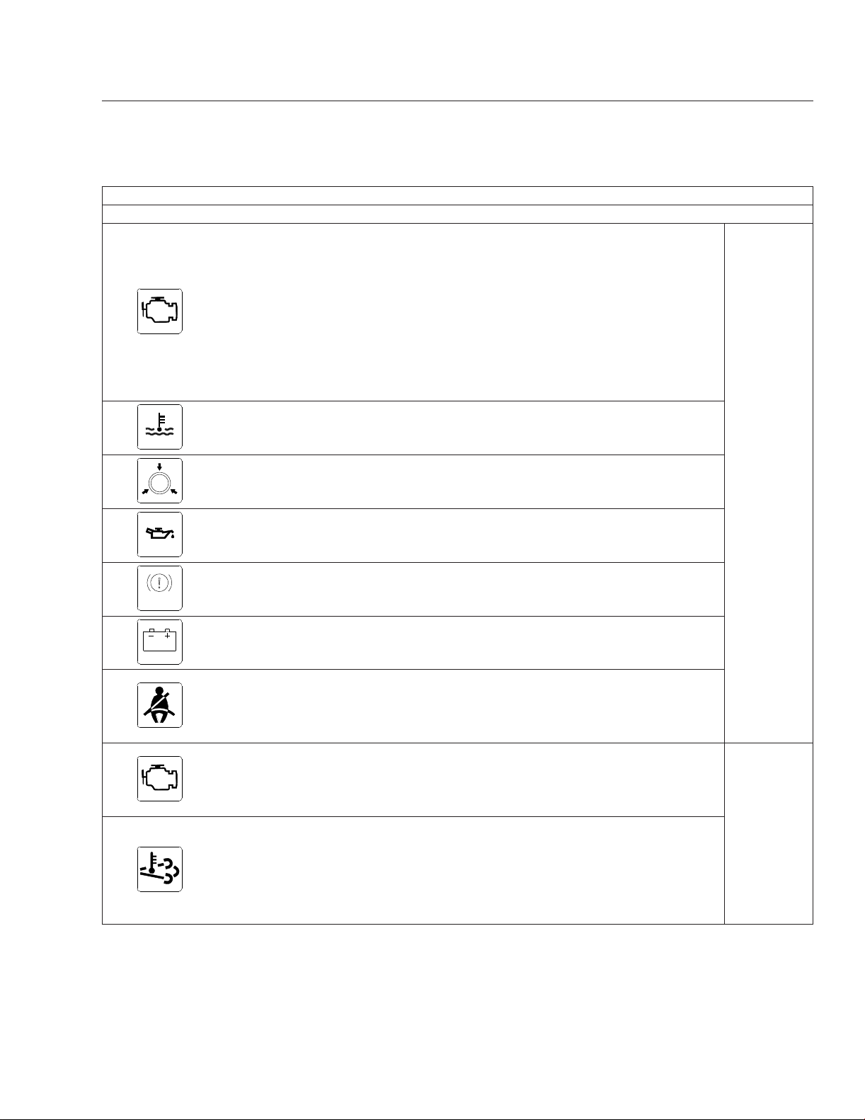
Common Warning and Indicator Lamps
Lamp Description Color
Indicates a serious fault that requires engine shutdown
immediately. The engine protection system will reduce the
maximum engine torque and speed, and, if the condition
does not improve, will shut down the engine within 30 to 60
seconds.
*
Safely bring the vehicle to a stop on the side of the road
and shut down the engine as soon as the red light is seen.
IMPORTANT: If the engine shuts down while the vehicle
is in a hazardous location, turn the key to the OFF
position for a few seconds, then restart the engine and
move the vehicle to a safer location.
Instruments
BRAKE
CHECK
High Coolant Temperature
Low Air Pressure
Low Engine Oil Pressure
Indicates the coolant temperature is above the maximum
allowable temperature.
Indicates air pressure in the primary or secondary reservoir
is below 70 psi (483 kPa).
Indicates the engine oil pressure is below the minimum
allowable pressure.
Indicates the parking brake is engaged. An audible alert
Parking Brake
activates when the vehicle is moving over 2 mph (3 km/h)
with the parking brake set.
Low Battery Voltage Indicates that battery voltage is 11.9 volts or less.
Activates with an audible alert when the system detects that
the parking brake is off and the driver seat belt is not
Unfastened Seat Belt
fastened on some vehicles. On other vehicles, this lamp
illuminates for 15 seconds when the ignition is first turned
on.
Indicates an engine condition (low oil pressure, low coolant
level, high coolant temperature, high DPF soot level, or
CHECK Engine
*
uncontrolled DPF regeneration) that requires correction.
Correct the condition as soon as possible. If the condition
worsens, the STOP engine lamp will illuminate.
Slow (10-second) flashing indicates a regeneration (regen)
is in progress.
High Exhaust System
Temperature (HEST)
IMPORTANT: When the HEST lamp is illuminated, do
*
not park the vehicle near flammable material.
Solid illumination indicates high exhaust temperatures at the
outlet of the tail pipe when speed is below 5 mph (8 km/h).
Red
Amber
4.4
Instruments
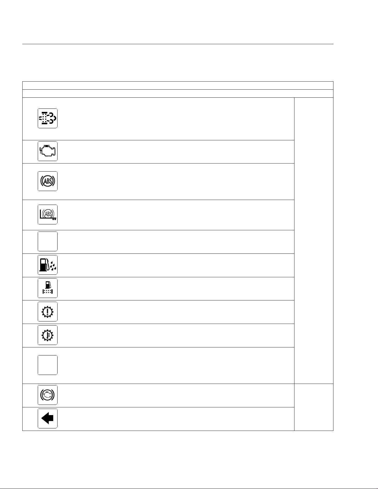
Diesel Particulate Filter
(DPF) Status
Common Warning and Indicator Lamps
Lamp Description Color
Solid illumination indicates a regen is required. Change to a
more challenging duty cycle (such as highway driving ) to
raise exhaust temperatures for at least twenty minutes, or
perform a parked regen.
Blinking indicates that a parked regen is required
immediately. An engine derate and shutdown will occur.
NO
CHARGE
Malfunction Indicator
Lamp (MIL)
Vehicle ABS
Trailer ABS
No Charge
Water in Fuel
Fuel Filter Restriction Indicates the fuel filter is clogged and requires service.
Check Transmission Indicates an undesirable transmission condition.
Indicates an emissions-related fault. See the engine
operation manual for details.
Momentary illumination indicates the vehicle ABS is
engaged.
Solid illumination indicates a problem with the vehicle ABS.
Repair the ABS immediately to ensure full braking
capability.
Momentary illumination indicates the trailer ABS is engaged.
Solid illumination indicates a problem with the trailer ABS.
Repair the ABS immediately to ensure full braking
capability.
Indicates the alternator is not properly powering the
electrical system.
Indicates the fuel may contain water. Drain any water
collected in the fuel/water separators.
Amber
4.5
WHEEL
SPIN
Transmission Overheat Indicates high transmission temperature.
Flashing indicates the ATC system is active, or the ATC
button has been pressed to allow wheel slip.
Wheel Spin
Engine Brake Indicates the engine brake is enabled.
Left-Turn Signal
Solid illumination indicates a problem with the ATC system.
Repair the ATC system immediately to ensure full braking
capability.
Flashing indicates the outside left-turn signal lights are
activated.
Green
Instruments
Common Warning and Indicator Lamps
Lamp Description Color
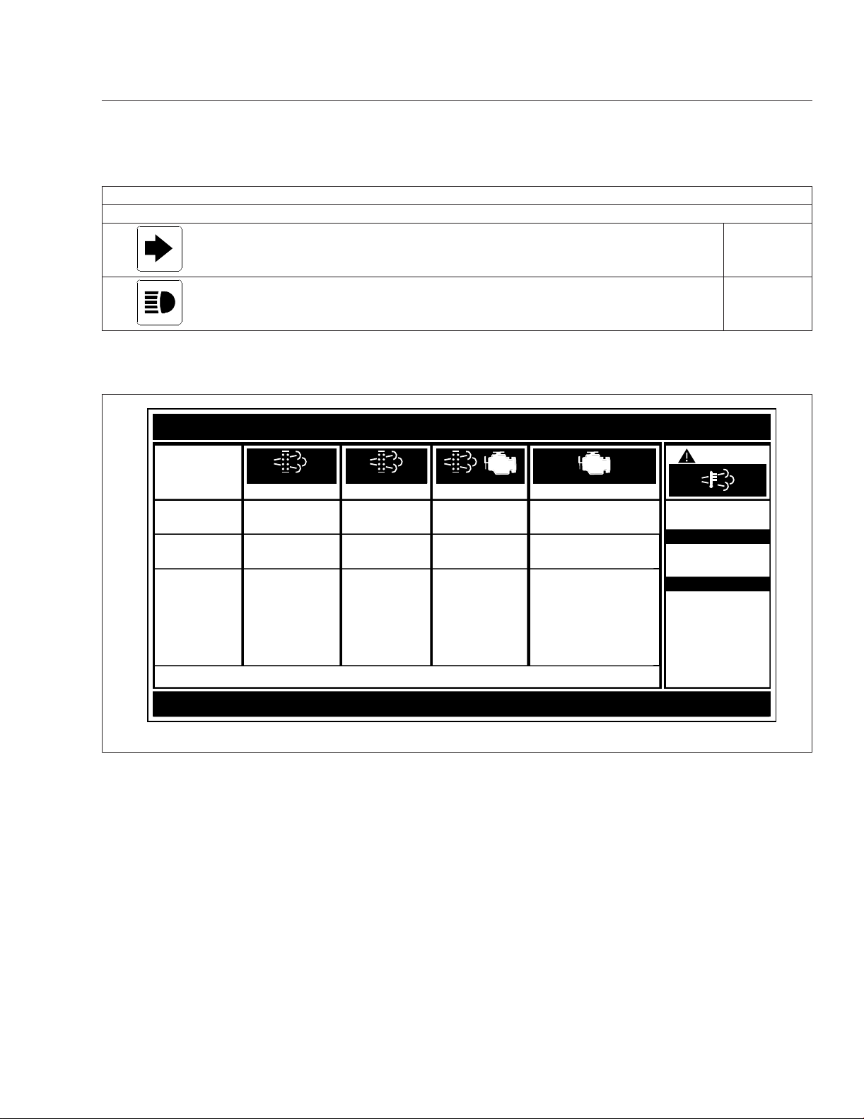
Right-Turn Signal
Flashing indicates the outside right-turn signal lights are
activated.
High-Beam Headlights Indicates the high-beam headlights are on. Blue
*
See Fig. 4.5 for an explanation of the aftertreatment system (ATS) warning indicators, and actions required to avoid further engine protection steps.
Table 4.1, Common Warning and Indicator Lamps
EXHAUST AFTERTREATMENT SYSTEM INFORMATION
INDICATOR
LAMP(S)
(Solid)
(Flashing) (Flashing)
CHECK
STOP
Level 1 Level 3Level 2 Level 4
Indicator Lamp
Message(s)
Diesel Particulate
Filter Condition
Required Action
For a driver performed Parked Regeneration, vehicle must be equipped with a dash mounted Regeneration Switch.
Filter Regeneration
Recommended.
Filter is reaching
capacity
.
Bring vehicle to
highway speeds to
allow for an
Automatic
Regeneration or
perform a Parked
Regeneration.
Filter
Regeneration
Necessary
Filter is now
reaching maximum
Switch.
capacity
.
To avoid engine
derate, bring vehicle
to highway speeds
to allow for an
Automatic
Regeneration, or
perform a Parked
Regeneration as
soon as possible.
Parked Regeneration
Required − Engine
Derate
Filter has reached
maximum capacity
Vehicle must be
parked, and a Parked
Regeneration must
be performed.
Engine will begin
derate.
.
Service Regeneration Required.
Engine Derate To Idle Only.
Filter has exceeded maximum
capacity.
Vehicle must be parked, and a
Service Regeneration must be
performed. Check engine
operator’s manual for details.
Engine will shut down.
W
ARNING
HEST (High Exhaust
System Temperature)
Flashing
A regeneration is in
progress.
Solid
Exhaust components
and exhaust gas are at
high temperature. When
stationary, keep away
from people and
flammable materials or
vapors.
Green
02/20/2009
Fig. 4.5, ATS Warning Lamps
On other engines, the engine protection system will
shut down the engine. It will first derate the engine,
then shut it down completely 30 to 60 seconds after
the indicator illuminates (depending on the critical
fault type) if the condition does not improve. Bring
the vehicle to a stop on the side of the road before
the engine shuts down.
Some vehicles may have a shutdown-override
switch, which may be used to momentarily override
the shutdown sequence. See
Chapter 10 for detailed
information regarding the shutdown process.
f080156
IMPORTANT: Do not attempt to restart the engine while the vehicle is moving. Bring the vehicle to a safe stop, then restart the engine.
To restart the engine, turn the ignition switch to OFF
for a few seconds, then turn the ignition switch to ON
and let the gauge sweep complete before starting the
engine. The engine will run for a short period and
shut down again if the condition does not improve.
4.6
Instruments
Instruments
Standard instruments are present on every vehicle.
Optional instruments, typically located on the auxiliary dash panel or right-hand control panel, are not
found on every vehicle. Instruments are listed here in
alphabetical order to make the information easier to
find.
Air Intake Restriction Gauge
The air intake restriction gauge indicates the vacuum
on the engine side of the air cleaner. On standard
installations, it is mounted on the air cleaner. As an
option for easier viewing, an air intake restriction indicator (see
dash panel.
Fig. 4.6) can be mounted on the auxiliary
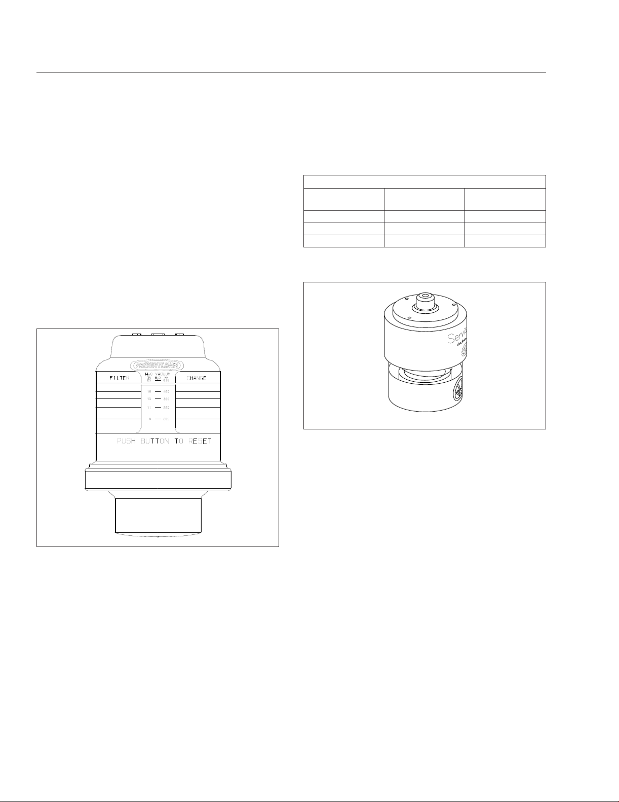
Vehicles may be equipped with a go/no-go restriction
indicator without graduations (see
a graduated indicator.
Air Intake Maximum Restriction Values (inH2O)
Engine Make
Cummins 25 25
Detroit 20 22
Mercedes-Benz 22 22
Table 4.2, Air Intake Maximum Restriction Values
04/08/2005 f090431
Pre-EPA07 (ADR
80/02) Engines
Fig. 4.7) instead of
EPA07 (ADR 80/
03) Engines
10/10/2001
Fig. 4.6, Air Intake Restriction Indicator
f610568
NOTE: Rain or snow can wet the filter and
cause a temporary high reading.
Air intake restriction vacuum is measured in inches
of water (inH2O). For vehicles equipped with a
graduated indicator or a restriction gauge on the
dash, check the gauge with the engine off. If the yellow signal stays locked in the red zone once the engine is shut down, or is at or above the values
shown in
be replaced.
Table 4.2, the air cleaner element needs to
Fig. 4.7, Manual-Reset Air Restriction Indicator, Go/
No-Go
If air restriction exceeds the maximum allowable
value, operate the vehicle for one more day, making
sure not to run the engine over rated rpm. Refer to
the engine operation manual for more information on
rated rpm for your engine.
If air restriction exceeds the maximum value again,
replace the air cleaner. For instructions, refer to
Group 09 of the Century Class Trucks Workshop
Manual.
Application Air Pressure Gauge
An application air pressure gauge registers the air
pressure being used to apply the brakes, and should
be used for reference only. The gauge will not register air pressure until the foot brake pedal is depressed or the trailer hand brake is applied.
4.7

Instruments
Coolant Temperature Gauge
NOTICE
A sudden increase in coolant temperature may
indicate engine or cooling system failure. Bring
the vehicle to a safe stop and investigate the
cause to prevent further damage. Do not operate
the engine until the cause has been determined
and corrected.
During normal engine operation, the coolant temperature gauge should read 175 to 195°F (79 to
91°C). If the temperature remains below 160°F
(71°C), inspect the cooling system to determine the
cause.
If coolant temperature rises above the maximum
temperature listed in
lamp will illuminate. If the condition does not improve, the STOP engine lamp will also illuminate and
an audible warning will sound. The engine will then
derate or shut down, depending on the type of engine protection system installed.
Maximum Coolant Temperature
Engine Make Temperature: °F (°C)
Cummins 225 (107)
Detroit 215 (101)
Mercedes-Benz 221 (105)
Table 4.3, Maximum Coolant Temperature
Table 4.3, the CHECK engine
Drive Axle Oil Temperature Gauges
NOTICE
Under heavy loads, such as when climbing steep
grades, temperatures that exceed the normal oil temperature range for a short period are not unusual. If
the temperature returns to normal when the load decreases, there is no problem.
Engine Oil Pressure Gauge
NOTICE
A sudden decrease or absence of oil pressure
may indicate mechanical failure. Bring the vehicle
to a safe stop and investigate the cause to prevent further damage. Do not operate the engine
until the cause has been determined and corrected.
The engine oil pressure gauge displays the current
engine oil pressure. If engine oil pressure falls below
the minimum levels shown in
engine lamp will illuminate. If the condition does not
improve, the STOP engine lamp will also illuminate
and an audible warning will sound. The engine will
then derate or shut down, depending on the type of
engine protection system installed.
Minimum Oil Pressure
Engine Model
Cummins 15 (103) 35 (241)
Detroit 14 (97) 55 (350)
Mercedes-Benz 7 (50) 36 (250)
*
Oil pressures are given with the engine at operating temperature. With
the engine cold, oil pressure may be higher. Individual engines may vary
from the listed pressures; observe and record pressures when the engine
is new to create a guide for checking engine condition.
Table 4.4, Minimum Engine Oil Pressure
At Idle Speed:
psi (kPa)
Table 4.4, the CHECK
*
At Rated RPM:
psi (kPa)
A sudden increase in oil temperature that is not
caused by a load increase may indicate mechanical failure. Bring the vehicle to a safe stop and
investigate the cause to prevent further damage.
Do not operate the vehicle until the cause has
been determined and corrected.
During normal operation, drive axle oil temperature
gauges should read as follows:
•
160 to 220°F (71 to 104°C) for Detroit™and
Meritor™drive axles
•
180 to 200°F (82 to 93°C) for Dana Spicer®
drive axles
Engine Oil Temperature Gauge
NOTICE
A sudden increase in oil temperature that is not
caused by a load increase may indicate mechanical failure. Bring the vehicle to a safe stop and
investigate the cause to prevent further damage.
Do not operate the engine until the cause has
been determined and corrected.
During normal operation, the optional engine oil temperature gauge should read:
4.8

Instruments
•
200 to 260°F (93 to 126°C) for Detroit and
Cummins engines
•
177 to 203°F (81 to 95°C) for Mercedes-Benz
engines
Under heavy loads, such as when climbing steep
grades, temperatures that exceed the normal oil temperature range for a short period are not unusual. If
the temperature returns to normal when the load decreases, there is no problem.
Tachometer
The tachometer indicates engine speed in revolutions
per minute (rpm) and serves as a guide for shifting
the transmission and keeping the engine in the appropriate rpm range. For low idle and rated rpm, see
the engine identification plate.
Transmission Fluid Temperature
Gauge
Fuel Gauge
The fuel gauge indicates the level of fuel in the fuel
tank(s). A single fuel gauge is standard. If equipped
with an optional second fuel tank, each fuel tank
level is indicated on a separate gauge.
Primary and Secondary Air Pressure
Gauges
WARNING
If air pressure falls below minimum pressure, the
braking ability of the vehicle will be limited. Slow
the vehicle down and bring it to a gradual stop.
Do not attempt to move the vehicle until air pressure has risen above the minimum level. Moving
a vehicle without adequate braking power could
cause an accident resulting in property damage,
personal injury, or death.
Air pressure gauges register the pressure in the primary and secondary air systems. Normal pressure,
with the engine running, is 100 to 120 psi (689 to
827 kPa) in both systems.
A low-air-pressure warning light and audible alert,
connected to both the primary and secondary systems, activate when air pressure in either system
drops below 64 to 76 psi (441 to 524 kPa).
When the engine is started, the warning light and
audible warning remain on until air pressure in both
systems exceeds minimum pressure.
Speedometer
Two speedometer options are available. The U.S.
version of the speedometer registers speed in both
miles per hour (mph) and kilometers per hour (km/h),
with mph in larger numbers. The metric version of
the speedometer face reverses this arrangement,
with km/h in larger numbers.
The transmission fluid temperature gauge indicates
the transmission lubricant operating temperature.
Temperatures vary by application, but the transmission fluid temperature gauge reading should not exceed 250°F (121°C).
NOTICE
A sudden increase in transmission fluid temperature that is not caused by a load increase may
indicate mechanical failure. Bring the vehicle to a
safe stop and investigate the cause to prevent
further damage. Do not operate the vehicle until
the cause has been determined and corrected.
Under heavy loads, such as when climbing steep
grades, temperatures that exceed the normal oil temperature range for a short period are not unusual. If
the temperature returns to normal when the load decreases, there is no problem.
Turbocharger Boost Pressure Gauge
A turbocharger boost pressure gauge indicates the
pressure in the intake manifold, in excess of atmospheric pressure, being created by the turbocharger.
Voltmeter
The voltmeter indicates the vehicle charging system
voltage when the engine is running and the battery
voltage when the engine is off. By monitoring the
voltmeter, the driver can stay aware of potential battery charging problems and have them fixed before
the batteries discharge enough to create starting difficulties. Argosy vehicles are equipped with either a
voltmeter gauge, or a digital voltmeter readout located on the bottom line of the dash message center.
The voltmeter will normally show approximately 13.7
to 14.1 volts when the engine is running. The voltage
of a fully charged battery is 12.7 to 12.8 volts when
the engine is off. Battery voltage under 12.0 volts is
4.9

Instruments
considered a low battery, and a completely discharged battery will produce only about 11.0 volts.
If the voltmeter shows an undercharged or overcharged condition for an extended period, have the
charging system and batteries checked at an authorized Freightliner service facility.
On a vehicle equipped with a battery isolator system,
the voltmeter measures the average voltage of all the
batteries when the engine is running. When the engine is off, the voltmeter shows only the isolated battery voltage and does not indicate the voltage of the
engine-starting batteries.
Driver Message Center
The dash message centers for the following instrument clusters are described below:
•
ICU4M
•
ICU3
•
ICU2M
ICU4M
Functions
A keypad located on the auxiliary dash panel controls
the driver message center. See
Fig. 4.8.
•
A flashing alert message that appears on the
driver message center in low engine oil pressure or high coolant temperature conditions.
With the parking brake off, only the odometer and
alert screens will display. Park the vehicle and set
the parking brake to access additional screens.
The dash message center displays alert screens
when certain conditions occur. They are warnings,
cautions, or other messages that require the driver’s
attention, but not all of them are critical to the operation of the vehicle. Warning messages always display
at full brightness.
More important messages take priority over less important messages. The order of priority is:
1.
parking brake set (with the vehicle moving)
2.
parking brake off (with the door open)
3.
low oil pressure or high coolant temperature
4.
hard brake warnings (if equipped with roll stability advisor)
5.
low battery voltage
6.
turn signal on
7.
service warnings
8.
no datalink activity
Dedicated Keys
08/08/96
To reset a value, press the SET/RESET button twice.
Fig. 4.8, ICU4M/ICU2M Keypad
Main features of the ICU4M include:
•
Gauges that sweep 270 degrees and have
pointers lit by an LED.
•
Service intervals that are programmable via
two dash-mounted switches.
•
An audible warning and alert message to warn
the driver if the door is opened without first setting the parking brake.
General Keys
Control Keys
f601009
Alert Screens
NOTE: If there is more than one alert message
to display, tap any key to access the next message, and so on, until all the messages have
been viewed.
Parking Brake On
This warning message and an audible warning come
on whenever the parking brake is applied and the
vehicle is moving faster than 2 mph (3 km/h). The
screen and audible warning go away only when the
parking brake is released, or speed is reduced below
2 mph.
Low Oil Pressure
This warning message and an audible warning come
on whenever the oil pressure falls below the minimum oil pressure, whether the vehicle is idling or in
motion. Tap any key to dismiss the message.
4.10

Instruments
If the fault is still active 30 seconds after the message is dismissed, the warning message will come
on again.
High Coolant Temp
This message and an audible warning come on
whenever the engine coolant temperature exceeds
the maximum allowable temperature.
If the fault is still active 30 seconds after the message is dismissed, the warning message will come
on again.
Low Voltage
On some vehicles, this optional message and an audible warning come on whenever the ICU detects a
low voltage condition.
Turn Signal On
This warning message and audible warning come on
whenever the turn signal remains on for four minutes
or five miles of travel.
To dismiss this message, either turn off the turn signal or tap any key.
Service Warnings
Service warning screens display during the ignition
sequence and indicate that a service interval has
been reached or exceeded and maintenance is required. The messages may indicate the number of
miles (KM) or hours until the next required service or,
once passed, the number of miles (KM) or hours ago
that maintenance should have been performed.
Automated Transmission Display
The ICU4M can display current gear information for
vehicles with an automated transmission. The last
three digits at the far right on the lower line of the
driver display screen are reserved for this information.
If there is a request to shift, an up or down arrow is
also displayed, depending on the shift direction.
On vehicles with conventional manual or automatic
transmissions, the gear and shift direction are not
displayed. For more information about specific
models of automated transmissions, see
Chapter 8.
Mobile Screens
The following screens are available when the parking
brake is off (when the vehicle is mobile).
i.
Fasten seat belt (rpm<100)
ii.
Fuel economy (rpm>100)
iii.
Odometer
iv.
Trip distance/hours
v.
Trip advisory
vi.
Leg distance/hours
vii.
Leg advisory
viii.
Outside air temperature
ix.
Fuel used/average MPG (KM/L)
Stationary Screens
NOTE: Metric unit screens are similar. AMT=
Current gear information for automated manual
transmissions.
The following screens are available when the parking
brake is on (when the vehicle is stationary).
i.
Odometer
ii.
Trip information including trip miles/hours, idle
hours, average speed, leg miles/hours
iii.
Fuel information including fuel used, fuel
economy, idle/PTO fuel usage
iv.
Engine information including engine miles/hours,
engine/PTO gallons, oil level
v.
Diagnostic information
vi.
Service information including mileage or time to
next service
vii.
Setup information
viii.
Vehicle information including Datalink status, ICU
serial number, software version
ix.
Fasten seat belt warning
Trip Information
When idle hours are displayed, tap the any key to
access the main trip information screen. See
Fig. 4.9. Tap the arrow keys on the 10-key keypad to
advance through the screens. Press and hold the
SET/RESET key to reset any of the screens.
4.11

FASTEN SEATBELTS
123456.7 MILES AMT
Instruments
Engine Idling
(100 RPM or more)
IDLE HOURS 1234:56
12.3GAL123456.7MI AMT
TRIP
INFORMATION AMT
12/01/2004 f040699
Go to Fuel Information Screens
Press Right Arrow Key and Set the Parking Brake
TRIP MILES 123456.7
TRIP HR 1234:56 AMT
R R R
IDLE HOURS 1234:56
AVG MPH 12.3 AMT
LEG MILES 123456.7
LEG HR 1234:56 AMT
Fig. 4.9, ICU4M Trip Information Screens
Fuel Information
Fuel information allows you to view total fuel usage
since the last reset, fuel mileage, and fuel consumed
while idling or running the PTO. See
the arrow keys on the 10-key keypad to advance
through the screens. Press and hold the SET/RESET
key to reset any of the screens.
Fig. 4.10.Tap
Press and hold the SET/RESET key to reset any of
the screens.
Diagnostic Information
If active fault codes are displayed on the diagnostic
information screens, make a note of the fault code
and text message, then take the vehicle to an authorized Freightliner service facility as soon as possible.
Fig. 4.12 for a diagram of the diagnostic infor-
Engine Information
The engine information screens allow you to view
See
mation screens.
engine mileage and hours, and total fuel consumption. See
Fig. 4.11. Tap the arrow keys on the 10-key
keypad to advance through the screens.
12/17/2004
Return to
Idle Hours
Screen
Go to Engine Information Screens
Information
FUEL
INFORMATION AMT
From Trip
FUEL USED 12345.6
AVG MPG 12.34 AMT
R R
Fig. 4.10, ICU4M Fuel Information Screens
IDLE GALLONS
PTO GAL 12345.6 AMT
12.3
f040700
4.12

Instruments
12/01/2004
Return to
Idle Hours
Screen
From Fuel
Information
ENGINE
INFORMATION AMT
Go to Diagnostic Information Screens
Return to
Idle Hours
Screen
From Engine
Information
DIAGNOSTIC
INFORMATION AMT
ENG MILES 123456.7
ENG HOUR1234:78AMT
ENG GALLONS 123456.7
PTO GAL 12345.6 AMT
If Oil Level Low
If Oil Level OK
If Oil Level High
Fig. 4.11, ICU4M Engine Information Screens
ACTIVE FAULTS
12 or NONE AMT
MID(text) PID/SID(text)
FMI(text) MID#sPID#FMI#AMT
Fault # 1 Fault # n
ENG OIL LEVEL
LO −1 QTS AMT
ENG OIL LEVEL
LO −1 QTS AMT
ENG OIL LEVEL
OK AMT
ENG OIL LEVEL
HI 1 QTS AMT
MID(text) PID/SID(text)
FMI(text) MID#sPID#FMI#AMT
f040701
12 HIST DASH FAULTS
LAST CLR 123456.7AMT
2
PUSH RESET TO
CLEAR DASH FAULTS AMT
CLEARED AMT
12/17/2004
Go to Service Information Screens
Fig. 4.12, ICU4M Diagnostic Information Screens
Service Information
Service information allows you to view the next recurring service interval, expressed in either miles or
hours. See
deactivated, so they do not display at all.
Fig. 4.13. Service intervals can also be
MID(text) PID/SID(text)
FMI(text) MID#sPID#FMI#AMT
LAST OCCUR 123456.7
1234 TIMES AMT
FIRST OCCUR 123456.7
1234 TIMES AMT
R
ALL FAULTS
For programming service intervals, see Setup Information, below.
NOTE: If the vehicle has gone past the service
interval, the miles (km)/hours remaining
screen is replaced by the service was due
Hist Fault # 1
MID(text) PID/SID(text)
FMI(text) MID#sPID#FMI#AMT
LAST OCCUR 123456.7
1234 TIMES AMT
FIRST OCCUR 123456.7
1234 TIMES AMT
Hist Fault # n
f040702
4.13

Instruments
12/17/2004
Return to
Idle Hours
Screen
From Diagnostic
Information
SERVICE
INFORMATION AMT
SERVICE
INFORMATION AMT
Distance prior to reaching the
set Service Interval
INTERVAL IS SET TO
XXXXX MILES AMT
Go to Set−up Information Screens
INTERVAL IS SET TO
XXXX HOURS AMT
Go to Setup Information Screens
12345 MILES
TO NEXT SERVICE AMT
Time prior to reaching the
set Service Interval
1234 HOURS
TO NEXT SERVICE AMT
Distance traveled beyond the
OR
R
Time accumulated beyond the
OR
R
set Service Interval
SERVICE WAS DUE
12345 MILES AGO AMT
set Service Interval
SERVICE WAS DUE
1234 HOURS AGO AMT
R
R
NOTE: Service information screens only appear if the service interval is set to MILES or HOURS in Setup Information.
Fig. 4.13, ICU4M Service Information Screens
screen, followed by the number of miles(km)/
ICU3
hours since the service was due.
A mode/reset button, located on the right side of the
Setup Information
See Fig. 4.14 and Fig. 4.15 for diagrams of the
setup information screens.
Setup information allows you to program various features of the ICU4M environment, including:
A.
Service intervals (OFF/MILES/HOURS);
B.
Target MPG;
C.
LCD Lamp (ON/OFF);
D.
Driver message center brightness;
E.
Language (English/French/Spanish);
F.
Units of measurement (English/Metric);
G.
Driver select (ON/OFF)
H.
Reset parameters to original settings.
Vehicle Information Screens
The vehicle information screens display hardware
and software information, including the Freightliner
part number and switch ID of the ICU. See
Fig. 4.16.
ICU instrument cluster, is used to control the driver
message center. See
Fig. 4.2. Tap the mode/reset
button to advance one screen; press and hold the
button to select a menu choice or reset the display.
When the display resets, an audible chirp sounds.
Only four screens are accessible when the parking
brake is off (mobile screens). All screens are accessible when the parking brake is on (stationary
screens).
Mobile Screens
The following screens are available when the parking
brake is off (when the vehicle is mobile) and no active fault codes are found. Tap the mode/reset button
to scroll through the mobile screens.
i.
Odometer
ii.
Trip distance
iii.
Trip hours
iv.
Back to odometer
Stationary Screens
f040703
The following screens are available when the parking
brake is on (when the vehicle is stationary) and no
4.14

Instruments
PUSH SET KEY TO
Return to
Idle Hours
Screen
SETUP
INFORMATION AMT
Go to Vehicle Information Screens
12/17/2004
From Service
Information
CHANGE SERVICE AMT
To more Setup Information
Fig. 4.14, ICU4M Setup Information Screens (for service intervals)
Go to Setup Information Screens
12.3
ON
−−> AMT
ENGLISH
/ METRIC AMT
f040705
12/17/2004
PUSH SET KEY TO
CHANGE TARGET MPG AMT
PUSH SET KEY TO
CHANGE LCD LAMP AMT
PUSH SET KEY TO
CHANGE BRIGHTNESS AMT
PUSH SET KEY TO
CHANGE LANGUAGE AMT
PUSH SET KEY TO
CHANGE UNITS AMT
PUSH SET KEY TO
CHANGE PARAMETERS AMT
Go to Vehicle Information Screens
TARGET MPG:
S
<−−LESS MORE−−>AMT
LCD LAMP
S
<−−OFF
DISPLAY BRIGHTNESS
S
<−−DARK LIGHT−−>AMT
LANGUAGE:
S
FRENCH/SPANISH AMT
UNITS
S
ENGLISH
RESET PARAMETERS
S
<−−
NO−−> AMT
YES
Fig. 4.15, Other Setup Information
active fault codes are found. Tap the mode/reset button to scroll through the stationary screens. See
Fig. 4.17.
SERVICE INTERVAL
S
OFF/
MILES
/HOURS AMT
If Service Interval is set to MILES
PUSH SET KEY TO
CHANGE SERVICE MI
AMT
INTERVAL
S
<−−LESS MORE−−> AMT
XXXXX MILES
OR
SERVICE INTERVAL
S
OFF/
MILES / HOURS
AMT
If Service Interval is set to HOURS
PUSH SET KEY TO
CHANGE SERVICE HR
i.
Odometer
ii.
Trip distance
iii.
Trip hours
iv.
Select units
v.
Diagnostics
vi.
Clear screen (on vehicles with less than 255
AMT
INTERVAL
S
<−−LESS MORE−−> AMT
XXXX
HOURS
f040704
miles on the odometer)
vii.
Engine miles
viii.
Engine hours
ix.
Engine oil level
x.
Setup
xi.
Back to odometer
Trip Distance
When the odometer reading is displayed, tap the
mode/reset button once for trip distance. Press and
hold the mode/reset button to reset trip miles to zero.
Trip Hours
When trip distance is displayed, tap the mode/reset
button once for trip hours. Press and hold the mode/
reset button to reset trip hours to zero.
4.15

Instruments
Return to
Idle Hours
Screen
VEHICLE
INFORMATION AMT
Return to Trip Information Screens
01/11/2005
MI
12.3 VOLTS
TRIP MI
12.3 VOLTS
From Setup
Information
123456.7
Push
123456.7
Push
DATALINK ACTIVE
AMT
DATA LINK STATUS
USAGE 12% ERR1%AMT
Fig. 4.16, ICU4M Vehicle Information Screens
Push
Push
CLEAr
123456.7
MI
Default Odometer
Dispay Screen
Hold
To Reset Trip Miles
EC
DASH# XXX−XXXXX−XXX
SW# P1.2.3 AMT
Hold
Clear Defaults
To Dispay Total Engine Miles
EC = Engine Control
f040706
123456.7
TRIP HOURS
12.3 VOLTS
Push
SELECt
MI
Push
dIAG
MI HOURS
n
Push Push
Hold
To Reset Trip Hours
To Toggle between Units
Hold
MI<−−−−>KM
Hold
Dispay Diagnostics
n = Number of Active Fault Codes
MI = CYCLE Miles Enabled
HOURS = Cycle Hours Enabled
123456.7
EC
Push
EnG oIL
*Lo
Push
**MI **HOURS
**no
HOURS
SEtUP
To Dispay Total Engine Hours
EC = Engine Control
Hold
Dispay Oil Level
*Lo = Oil Level Low
HI = Oil Level High
Blank = Oil Level OK
− − = No Message
Dispay Service Interval
Hold
Cycle Screens
**MI = CYCLE Miles Active Mode
**HOURS = CYCLE Hours Active Mode
**no = Service CYCLE Inactive
03/26/2004 f040636a
Note: The engine oil level screen displays for Mercedes-Benz engines only (if equipped and enabled).
Fig. 4.17, ICU3 Stationary Screens
Diagnostic Information
When the DIAG screen is displayed, press and hold
the mode/reset button to access the various diagnostic screens.
Trained technicians use the diagnostic screens to
retrieve fault codes and other diagnostic information
pertaining to the vehicle. If active fault codes display
during start-up or at any other time, make a note of
4.16

Instruments
the fault code and take the vehicle to an authorized
Freightliner service facility as soon as possible.
If fault codes are displayed, press and hold the
mode/reset button to view the next fault code until
reaching the DIAG screen.
If service intervals are enabled and service distance
or time has been exceeded, the text SERVICE
HOUR/MI (KM) will display at start-up to indicate vehicle service is required.
Engine Information
When the DIAG screen is displayed, tap the mode/
reset button once to access the engine miles/hours
screen. When the engine miles/hours screen is displayed, press and hold the mode/reset button to access the engines screen sub-menu.
Setup Information
The setup screen allows the driver to manage ICU
parameters. When the engine hours/miles screen is
displayed, tap the mode/reset button to access the
setup screen. The setup screen submenu allows the
driver to enable and change service intervals.
For each parameter, press and hold the mode/reset
button to navigate to the parameter change screen.
In each change screen, tap the mode/reset button to
toggle between options.
When the setup screen is displayed again, tap the
mode/reset button to view the odometer.
ICU2M
A keypad located on the auxiliary dash panel controls
the driver message center. See
keypad is used to:
•
call up information on mobile screens;
•
navigate from screen to screen;
•
set up the display;
•
record significant data.
The odometer is a seven-digit display with one decimal point after the sixth digit, allowing it to display
tenths of miles (or kilometers). When first installed,
the odometer starts at 0.0 miles (or kilometers).
When replaced, the odometer starts again from 0.0.
Fig. 4.8. The 10-key
Alert Screens
Alert screens can appear at any time, even when the
vehicle is moving. They override the regular screen
display. They are warnings, cautions, or other messages that require the driver’s attention, but not all of
them are critical to the operation of the vehicle. The
word Warning or Alert sometimes flashes on the
display screen above the alert text. More important
messages take priority over less important messages.
NOTE: If there is more than one alert message
to display, press any button to scroll to the next
message, and so on until all the messages have
been viewed.
Parking Brake On
This warning message and an audible warning come
on whenever the parking brake is applied and the
vehicle is moving faster than 2 mph (3 km/h). The
screen and audible warning go away only when the
parking brake is released, or speed is reduced below
2 mph (3 km/h).
Low Oil Pressure
NOTE: All alert screens follow Low Oil Pressure
alert format.
This warning message and an audible warning come
on whenever the oil pressure falls below the minimum oil pressure, whether the vehicle is idling or in
motion. See
press any button on the keypad.
If low oil pressure is detected during the ignition sequence, it displays as an active fault and the alert
screen does not appear. After 30 seconds, this message displays again.
Fig. 4.18. To dismiss the message,
Low Coolant Level
This warning message and audible warning activate
whenever the coolant level falls below a preset point.
High Coolant Temp
This message and an audible warning come on
whenever the engine coolant temperature exceeds
the maximum allowable temperature.
If high coolant temperature is detected during the
ignition sequence, it displays as an active fault and
4.17

INITIAL
WARNING
PRESS ANY KEY
NORMAL OPERATION
SCREEN
WARNING
LOW OIL PRESSURE
BLINKING
WARNING
RETURN TO
NORMAL
OPERATION
Instruments
Low Fuel Level
The ICU continuously monitors fuel level. When the
fuel level drops to 1/8th full, the word Warning
flashes on the message display screen above the
low fuel alert.
Turn Signal On
This message (the audible warning is optional) appears whenever the turn signal remains on beyond a
preset time or distance traveled.
To dismiss this message, either turn off the turn signal or press any button on the keypad.
08/17/95
NOTE: All Alert Screens follow this format.
Fig. 4.18, ICU2M Alert Screen: Low Oil Pressure
f040307
the alert screen does not appear. After 30 seconds,
this message displays again.
Low Voltage
On some vehicles, this optional message and an audible warning come on whenever the ICU detects a
low voltage condition.
Faulty Speedo Gauge
This message is displayed when the system detects
a faulty speedometer. This becomes the default
screen, and vehicle speed is displayed as a digital
readout at the bottom left of the screen. All other
screens and functions operate normally.
Recirc Mode Engaged/Provide Fresh Air
The Recirc Mode Engaged message appears whenever recirculated air is selected on the fresh/air recirculation switch or the air circulation switch is rotated
to the maximum air conditioning position. It displays
one time only for seven seconds. It notifies the driver
that recirculated air is being used and that fresh air
needs to be provided after 20 minutes.
If fresh air is not provided after 20 minutes, Provide
Fresh Air is displayed. It displays for seven seconds
approximately every four minutes until the driver selects fresh air on the fresh/air recirculation switch or
rotates the air circulation switch away from maximum
air conditioning. See
instructions for the heater/air conditioner.
Chapter 4 for detailed operating
Service Warnings
Service warning screens display during the ignition
sequence and indicate that a service interval has
been reached or exceeded and maintenance is required. The messages may indicate the number of
miles (KM) or hours until the next required service or,
once passed, the number of miles (KM) or hours ago
that maintenance should have been performed. The
ICU2M can be programmed using ServiceLink to
generate service warnings in either miles or hours,
but not both.
No Datalink Activity
This message appears whenever the datalink is not
receiving data. If the condition persists, take the vehicle in for service as soon as possible to discover
the cause of the problem.
Mobile Screens
The following screens are available when the parking
brake is off (when the vehicle is mobile) and no active fault codes are found. Press the appropriate button on the keypad to display one of the mobile
screens.
•
trip miles and hours
•
fuel used and average MPG
•
leg miles and hours
NOTE: Resetting trip miles and hours also resets leg miles and hours.
To reset a mobile screen, push the Set/Reset button
twice within a 6-second period while the screen is
displayed. A confirmation screen will display after you
press the button once.
4.18

Instruments
NOTE: If the memory in the data logger is full,
the screen will display Memory Full Data Not
Recorded. If the data logger is not connected
or not responding, the screen will display Data
Recorder Not Responding. If the EVENT button was pressed within the last two minutes, the
screen will display Still Recording Last Event.
Stationary Screens
The following screens are available when the parking
brake is applied (vehicle is stationary) and no active
fault codes are found. Each set of stationary screens
has a title screen followed by one or more data
screens.
To move forward and backward through these
screens, use the three arrow buttons on the keypad.
Fig. 4.19, Fig. 4.20, and Fig. 4.21 for stationary
See
screen navigation.
i.
Trip Information: miles, hours
ii.
Fuel information: fuel used, average MPG
iii.
Engine information: engine miles and hours, engine gallons and PTO gallons
iv.
Diagnostic information: active faults, historical
dash faults
v.
Setup Information: target MPG, brightness, language, units of measurement
vi.
Vehicle information: datalink activity/status, ICU
part number, software ID number
Overhead Instrument Panel
The optional overhead instrument panel may hold a
citizen’s band (C/B) radio, digital clock, storage
pocket areas for sunglasses and maps, and a locked
glove box.
The underside of the overhead console also holds
the sun visors and the optional dome/reading light
assembly. See
the dome/reading light assembly.
Chapter 5 for more information on
02/13/96
IDLE HOURS 1234.56
12.3 GAL 1234567 MI
FASTEN SEATBELTS
1234567 MILES
IGNITION
ON ONLY
IDLING
DIAGNOSTIC
INFORMATION
See applicable Figure.
Fig. 4.19, ICU2M Engine Information and Diagnostic Information
See applicable Figure for trip and fuel information.
ENGINE
INFORMATION
ACTIVE FAULTS
1234 or NONE
123 HIST DASH FAULTS
LAST CLEAR 1234567
ENG MILES 1234567.8
ENG HOURS 123456:78
For each fault, display fault codes and description.
FIRST SECOND
For each fault, display fault codes and description.
FIRST
LAST OCCR
FIRST OCCR
ENG GALLONS 123456.7
PTO GALLONS 123456.7
LAST
LAST OCCR
FIRST OCCR
R
S
CLEAR DASH FAULTS
=RESET (PUSH RESET/SET KEY TWICE)
=SET (PUSH RESET/SET KEY ONCE)
LAST
PUSH RESET TO
R
f040325
4.19

Instruments
01/29/98
See
applicable
Figure.
SETUP
INFORMATION
VEHICLE
INFORMATION
To trip information
See applicable Figure.
PUSH SET KEY TO
CHANGE TARGET MPG
PUSH SET KEY TO
CHANGE BRIGHTNESS
PUSH SET KEY TO
CHANGE LANGUAGE
PUSH SET KEY TO
CHANGE UNITS
DATA LINK ACTIVE
S
S
S
S
TARGET MPG 7.0
<−−LESS MORE−−>
DISPLAY BRIGHTNESS
<−−LIGHT DARK−−>
CURRENT LANGUAGE
IS FLASHING
LANGUAGE ENGLISH
FRENCH SPANISH
CURRENT UNITS
IS FLASHING
UNITS
ENGLISH METRIC
DATA LINK STATUS
USAGE 40% ERROR 6%
R
=RESET (PUSH RESET/SET KEY TWICE)
S
S
S
S
S
=SET (PUSH RESET/SET KEY ONCE)
Fig. 4.20, ICU2M Setup Information and Vehicle Information
DASH #
SW#
A06−XXXXX−XXX
7.3.9
f040326a
4.20

Instruments
IDLE HOURS 1234:56
12.3 GAL 1234567 MI
FASTEN SEATBELTS
1234567 MILES
IGNITION
ON ONLY
01/28/98
IDLING
TRIP
INFORMATION
FUEL
INFORMATION
ENGINE
INFORMATION
TRIP MILES 123456.7
TRIP HOURS 1234:56
FUEL USED 12345.6
AVERAGE MPG 12.34
ENG MILES 1234567.8
ENG HOURS 123456:78
IDLE HOURS 1234:56
AVERAGE MPH 12.3
R R R
IDLE GALLONS 12345.6
PTO GALLONS 12345.6
R R
ENG GALLONS 123456.7
PTO GALLONS 123456.7
R
=RESET (PUSH RESET/SET KEY TWICE)
=SET (PUSH RESET/SET KEY ONCE)
S
See applicable figure
Fig. 4.21, ICU2M Trip Information, Fuel Information, and Engine Information
LEG MILES 123456.7
LEG HOURS 1234:56
f040324a
4.21

5
Driver Controls
Ignition Switch and Key ............................................................ 5.1
Lighting Controls .................................................................. 5.2
Horn Controls .................................................................... 5.4
Powertrain Controls ............................................................... 5.5
Cruise Control .................................................................... 5.7
Dash-Mounted Brake Controls ....................................................... 5.8
Windshield Wiper/Washer Controls .................................................. 5.10
Suspension/Trailer Connection Controls .............................................. 5.10
Climate Controls ................................................................. 5.11
Seat Controls ................................................................... 5.12
Adjustable Steering Column Controls ................................................ 5.12

Driver Controls
Ignition Switch and Key
The ignition switch has four positions: OFF, ACC (accessory), ON, and START. See
key also locks and unlocks the cab doors, baggage
door(s), and if equipped, the bunk door(s).
07/19/2006 f610805
Fig. 5.1, Ignition Switch
In the OFF position, the ignition switch is vertical.
The key can be inserted and removed only in the
OFF position.
The following functions are operable when the ignition switch is in the OFF position (regardless of
whether the key is inserted):
•
low-beam headlights
•
taillights
•
brake lights
•
road lights
•
dome lights
•
clearance lights
•
hazard warning lights
•
turn signals
•
utility lights
•
baggage compartment lights
•
spotlights
•
electric horn
•
clock
•
refrigerator
Fig. 5.1. The ignition
•
CB radio
•
power mirrors
•
power receptacle
•
fuel heater
•
electric oil pan heater
•
electric or diesel-fired engine coolant preheater
Turn the key counterclockwise to reach the ACC position. In addition to all the functions that are operable in the OFF position, the following functions are
operable when the switch is in the ACC position:
•
radio/stereo system
•
heater and A/C fan
•
mirror defog
•
windshield fan
•
ether start system
•
air dryer
•
backup lights
Turn the key clockwise past the OFF position to
reach the ON position. When the ignition is turned
on, the following actions should occur:
•
electronic gauges complete a full sweep of
their dials
•
warning and indicator lamps illuminate, then
are extinguished
•
audible alert sounds for approximately four
seconds or until sufficient air pressure builds
up in the primary and secondary air systems
•
software revision level of the ICU is displayed
on the driver message center, followed by any
active faults
IMPORTANT: If any red or amber warning or
indicator lamps do not illuminate during the ICU
self-check or do not extinguish after the selfcheck completes, take the vehicle to an authorized Daimler Trucks service facility as soon as
possible.
IMPORTANT: Do not crank the engine until the
ICU gauge sweep is complete.
5.1

Driver Controls
Turn the key clockwise past the ON position to reach
the START position to start the engine. Release the
key the moment the engine starts. Do not operate
the starter longer than thirty seconds, then allow the
starter to cool between attempts. If the starter overheats, the starter protection system will prevent operation of the starter until it has cooled. Release the
key the moment the engine starts.
Lighting Controls
Exterior Lighting Controls
Exterior light controls are listed here in alphabetical
order.
Backup Lights
Backup lights provide a warning to pedestrians and
other drivers that the vehicle is, or is about to, back
up.
Daytime Running Lights
The daytime running lights (DRL), if equipped, are
automatically activated when the ignition is switched
on and the parking brake is released. The DRL operate until the parking brake is applied or the headlights are turned on.
Some vehicles may be equipped with a momentary
DRL override switch. See
half of the switch to briefly deactivate the DRL.
Fog Lights
Fog lights are designed to reduce glare in foggy conditions. The low-beam headlights must be on in order
to turn the fog lights on. Press the upper half of the
switch to activate the fog lights. See
Hazard Warning Lights
The hazard warning light switch tab is located below
the turn signal lever. Pull the tab out to activate the
hazard warning lights. When the hazard warning
lights flash, all turn signal lamps and both of the indicator lights on the control panel will flash. Move the
turn signal lever up or down to cancel the warning
lights.
Headlights
A three-position paddle switch is used to operate the
exterior lights. See
Fig. 5.2. Press the upper
Fig. 5.2.
Fig. 5.2. Move the paddle switch
up to activate the headlights, instrument panel, clearance lights, marker lights, and taillights. To deactivate
all vehicle lighting, ensure the switch is in the middle
position. Move the paddle switch down to activate
only the clearance, instrument panel, marker lights,
and the taillights.
High-Beam Headlights
To activate the high-beam headlights, pull the turn
signal lever towards the driver while the low-beam
headlights are on. Pull the turn signal lever back
again to deactivate the high beams and return to low
beam headlights.
When the high-beam headlights are on, a blue light
illuminates on the instrument cluster.
NOTE: The ignition switch must be on for the
high beams to work.
Marker Light Interrupt
A momentary interrupt switch temporarily deactivates
the marker lights and taillights. With the vehicle lights
on, press and release the interrupt switch to briefly
turn the marker lights and taillights off. To alert the
driver that the switch is functioning, the dash lights
will flash with the marker lights when the switch is
actuated.
Road Lights
Press the upper half of the road light switch to activate the road lights mounted on the bottom edge of
the front bumper or recessed in the front bumper.
Fig. 5.2.
See
Spotlight
The spotlight switch is located on the pivoting handle
of the spotlight. There may be a single spotlight assembly mounted above the driver’s door, or one
above each door.
Turn Signals
The turn signal lever is mounted on the steering column. Push the lever down to activate the left-turn
signal lights; pull the lever up to activate the rightturn signal lights. To manually cancel the signal,
move the lever to the neutral position. When a turn
signal is activated, a green indicator light flashes on
the instrument cluster.
5.2

Driver Controls
1 2 3 4 5
04/24/2012 f611174
1. Spotlight Switch
2. Dome Light Switch
3. Utility Lights Switch
4. Foot Well Lights Switch
Utility Lights
Utility lights can be swivel-mounted on top of the
cab, mounted on the intake/exhaust support, or flushmounted in the back of the cab or sleeper. Press the
upper half of the switch to activate the utility lights.
Fig. 5.2. Press the lower half of the switch to
See
turn the utility lights off. When activated, a red indicator light in the switch is illuminated, if equipped
Interior Lighting Controls
Interior light controls are listed here in alphabetical
order.
Baggage Compartment Lights
Baggage compartment lights are located on the underside of the lower bunk, on both sides. Both lights
turn on when either baggage compartment door is
6 7 8 9 10
5. Road Lights Switch
6. Rear Strobe Light Switch
7. Front Strobe Light Switch
Fig. 5.2, Typical Light Controls
opened to illuminate the baggage compartment. The
lights also come on when the lower bunk is raised.
8. Fog Lights Switch
9. Headlights/Marker Lights Switch
10. DRL Override Switch
Cab Overhead Console Lights
The overhead console includes a clear reading light,
a clear dome light, and a red map light. The dome
lights illuminate when a door opens, then stay on for
a short time after both doors are closed. Press the
lens of the reading light, dome light, or map light to
activate each one.
Foot Well Lights
When the driver or passenger doors are opened, red
lights illuminate both foot wells. These lights can also
be activated with the foot well light switch. See
Fig. 5.2. Press the upper half of the switch to turn
the foot well lights on, press the lower half of the
switch to turn them off.
5.3

Driver Controls
5
6
5
4
3
11/21/2006 f544908
2
1
Fig. 5.4, Sleeper Dome Light
2
05/04/2012 f545896
1. Fog Light
2. Headlight
3. Front Turn Signal
Fig. 5.3, Exterior Lights
The sleeper foot well switch is located in the lower
switch module in the sleeper. It looks identical to the
cab foot well switch. See
is activated, two lights illuminate the sleeper floor.
4. Sidewall Turn Signal
5. Clearance Light
6. Marker Lights
Fig. 5.2. When the switch
1
Instrument Panel Lights
The instrument panel lights illuminate when the
headlights are turned on. When the headlights are
on, the panel lamp switch controls the intensity of the
instrument panel lamps. Slide the switch up to
brighten them and down to dim them. When the
headlights are turned on, the panel lights setting will
default to the intensity that was last set.
Sleeper Dome Light
A sleeper dome light is located on the roof, between
the bunk and the cab on sleeper vehicles. See
Fig. 5.4. The rear cab dome light will activate with
the dome lights when a door is opened, then stay on
for a short time after both doors are closed.
Use the dash-mounted switch or the switch in the
sleeper panel to activate the rear cab dome light.
Fig. 5.2.
See
Rear-Wall Dome Light
A rear-wall dome light is available on all sleeper
cabs. It is located on the rear wall where the wall
meets the roof. To turn on the rear-wall fluorescent
light, press the dome light switch on either the lower
or upper bunk control panels. See
Fig. 5.5.
Sleeper Reading Lights
Clear reading lights are mounted above the lower
bunk in the rear corners of the sleeper. There are
two switches in the sleeper control panel for the
reading lights. To turn a reading light on, press the
upper half of the switch. Press the lower half of the
switch to turn it off. See
The reading lights can also be activated by pressing
the lens.
Fig. 5.5.
Horn Controls
Air Horn
Air horn(s) may be mounted on the roof of day cabs,
or under the driver-side floor for sleeper cabs. The
air horn is controlled by a wire lanyard that hangs
down inboard by the driver’s door. See
downward on the lanyard to sound the air horn.
Electric Horn
The button for the electric horn on a vehicle without
an airbag is located in the center of the steering
wheel. To sound the horn, press down on the button.
Fig. 5.6. Pull
5.4

Driver Controls
4
3
5
6
2
7
1
05/04/2012 f611184
1. Clock
2. Volume Control Switch
3. Fan Switch
4. Reading Light
5. Temperature Control Switch
6. Dome Light Switch
7. Power Receptacle
Fig. 5.5, Sleeper Climate Control Panel
The electric horn on a vehicle with an airbag is activated by pressing down on the top of the steering
wheel center pad.
The horn will sound for the duration that the button is
pressed, up to 60 seconds. The electric horn will operate regardless of the position of the ignition key.
1
06/13/2007 f602322
1. Lanyard
Fig. 5.6, Air Horn Control
be equipped with an emissions aftertreatment
system (ATS).
The regen request switch, located on the dash, is
used to initiate a parked regen. See Fig. 5.7.
2
1
Powertrain Controls
Aftertreatment System Regen
Switches
NOTE: See Chapter 11 for detailed information
about the operation of the regeneration (regen)
switches and the aftertreatment system (ATS).
IMPORTANT: Depending upon local jurisdictional emissions guidelines, the vehicle may not
5.5
f61117504/24/2012
1. Regen Request Switch
2. Regen Request/Inhibit Switch
Fig. 5.7, ATS Regen Switches
NOTE: The regen switch can initiate a parked
regen only when the DPF lamp is illuminated.
Some vehicles may be equipped with a regen
request/inhibit switch. See Fig. 5.7. To stop a regen
in progress or prevent the start of a regen, press the

Driver Controls
lower half of the switch. Regen will be delayed until
the switch is no longer active.
Axle Switches
Differential Lock Switch
The differential lock switch provides maximum traction for slippery conditions by forcing the wheels on
each drive axle governed by the switch to rotate together. Engagement can be at any speed, provided
the wheels are not slipping or spinning. See
Fig. 5.8.
1
2
UNLOCK control valve switch. See
indicator illuminates when the interaxle lock is engaged.
Fig. 5.8. A red
NOTICE
The interaxle lock should only be engaged when
the vehicle is moving slowly at low throttle. Engagement at high speed or power can damage
the axle(s).
Do not permit rear wheels to spin freely for more
than ten seconds when traction is lost. Shift into
LOCK to prevent damage to interaxle and main
differentials.
Engine Fan Switch
To turn the engine fan on, press the upper half of the
engine fan switch. See Fig. 5.9. The fan will continue
to operate for a set amount of time and then turn off
unless the coolant temperature is high enough to
continue fan operation. To turn the fan off before the
set time period ends, press the lower half of the
switch.
3
4
01/05/2012 f611158
1. Interaxle Differential Lock Switch
2. Fifth Wheel Slide Switch
3. Rearmost Axle Differential Lock Switch
4. Air Suspension Dump Control Switch
Fig. 5.8, Axle and Suspension Switches
Interaxle Lock Switch
The interaxle lock, standard on all dual-drive vehicles, is driver-actuated by means of a LOCK/
f61117804/24/2012
Fig. 5.9, Engine Fan Switch
Hill Start Aid Override Switch
Some vehicles are equipped with a Hill Start Aid
(HSA) feature to prevent the vehicle from rolling
while on steep grades and to allow for a controlled
launch. HSA is active by default. It can be turned off
by pressing and releasing the HSA override switch
on the dash (see
Fig. 5.10).
5.6

Driver Controls
HSA
OVRD
f61119606/04/2012
Fig. 5.10, Hill Start Aid Override Switch
PTO Switch
To activate the PTO function, press the upper half of
the switch. Press the lower half of the switch to deactivate the PTO function.
Transmission Controls
Manual Transmissions
NOTE: See Chapter 14 for complete manual
transmission operating instructions.
If so equipped, the transmission range control and
splitter valves are attached to the gear shift knob.
The range-preselection lever allows the selection of
the low or high range for each transmission ratio. It is
used once during an upshift sequence and once during a downshift sequence.
Depending on the transmission model, some ratios
can be split using the splitter-control button.
Eaton Automated Transmissions
NOTE: See Chapter 15 for complete automated
transmission operating instructions.
The SmartShift electronic transmission control is installed with the Eaton® Fuller® UltraShift
Eaton Fuller AutoShift™transmissions. The SmartShift control is operated by the fingers of the driver’s
right hand, allowing both hands to remain on the
steering wheel.
A two-position driving mode slide switch is mounted
on the body of the control lever just before the
paddle widens out. The slide switch allows the driver
to choose automatic (AUTO) or manual (MAN) mode.
Fig. 5.11.
See
™
and
5
4
3
1
01/24/2003
To upshift manually, pull the lever back (towards the
driver). To downshift manually, push the lever forward
(away from the driver).
1. SmartShift Control Lever
2. Slide Switch (forward driving mode switch)
3. MAN Mode (of slide switch)
4. AUTO Mode (of slide switch)
5. Upshift Direction
6. Reverse Position (of selector switch)
7. Selector Switch
8. Neutral Lock Button
9. Neutral Position (of selector switch)
10. Drive Position (of selector switch)
11. Low Position (of selector switch)
12. Downshift Direction
Fig. 5.11, SmartShift Control (Eaton Fuller UltraShift
and AutoShift transmissions)
2
6
11
7
8
9
10
12
f270120
Cruise Control
WARNING
Do not use the cruise control system when driving conditions do not permit maintaining a constant speed, such as in heavy traffic or on roads
that are winding, icy, snow-covered, slippery, or
roads with a loose driving surface. Failure to follow this precaution could cause a collision or
loss of vehicle control, possibly resulting in personal injury or property damage.
NOTICE
When the cruise control is engaged, do not attempt to shift gears without using the clutch
pedal. Failure to follow this precaution will result
in a temporarily uncontrolled increase in engine
speed. Transmission damage and gear stripping
could result.
5.7

Driver Controls
Cruise control is activated by two dash-mounted
switches: an On/Off switch and a Set/Decelerate/
Resume/Accelerate switch. See
1
1. Set/Decelerate/Resume/Accelerate Switch
2. Cruise Control On/Off Switch
Fig. 5.12, Cruise Control Switches
Fig. 5.12.
2
f61118104/24/2012
Cruise at a particular speed
1.
Press the upper part of the cruise control On/Off
switch to turn cruise control on.
2.
Hold the accelerator pedal down until the speedometer reaches the desired speed.
3.
Press the lower half of the Set/Resume/
Accelerate/Decelerate switch momentarily to set
the cruise speed (with the vehicle moving at the
desired speed).
To decrease cruise speed, press and hold the
lower half of the Set/Resume/Accelerate/
Decelerate switch to decelerate slowly. Release
the switch when the desired speed is achieved.
To increase cruise speed, press and hold the
upper half of the Set/Resume/Accelerate/
Decelerate switch to accelerate slowly. Release
the switch when the desired speed is achieved.
Disengage cruise control
NOTE: The speed memory is lost whenever the
ignition is turned off or the cruise control system
is turned off.
1.
Depress the brake pedal (automatic or manual
transmissions)
or
Depress the clutch pedal (manual transmissions
only).
2.
Press the lower half of the On/Off switch.
NOTE: To resume the preselected cruise speed,
increase vehicle speed to above minimum
cruise control speed and momentarily press the
upper half of the Set/Resume/Accelerate/
Decelerate switch. Cruise will return to the last
speed selected.
Dash-Mounted Brake Controls
NOTE: See Chapter 12 for detailed information
about brake systems.
Antilock Braking System
The Meritor™WABCO® Antilock Braking System
(ABS) passively monitors vehicle wheel speed at all
times, and controls wheel speed during emergency
stops or wheel lock situations.
During emergency or reduced-traction stops, fully
depress the brake pedal until the vehicle comes to a
safe stop. Do not pump the brake pedal. With the
brake pedal fully depressed, the ABS will control all
wheels to provide steering control and a reduced
braking distance.
The ABS is designed to communicate with a trailer
ABS, if they are compatible. Compatibility will result
in the illumination of the trailer ABS lamp during vehicle start-up and fault detection. The trailer ABS
lamp will not illuminate unless a compatible trailer is
connected to the tractor.
Vehicles with ABS may have Automatic Traction Control (ATC). On these vehicles, the ATC system automatically limits wheel spin during reduced-traction
situations. In normal braking applications, the standard air brake system is in effect.
ATC includes a deep snow and mud option to increase available traction on extra-soft surfaces like
snow, mud, or gravel. A switch labeled ATC will be
located on the dash. See
to temporarily activate the snow/mud option. The activation of the deep snow and mud option is indicated
by a flashing WHEEL SPIN lamp. Press the switch
again to cycle the system back to normal operation.
Fig. 5.13. Press the switch
5.8

Driver Controls
The yellow diamond-shaped knob operates the parking brake valve. See
apply the tractor and the trailer spring parking
brakes. Push the knob in to release the spring parking brakes. Before the spring parking brakes can be
released, the air pressure in either air brake system
must be at least 65 psi (447 kPa).
If the trailer is not equipped with spring parking
brakes, pull the parking brake valve out to apply the
tractor parking brakes and the trailer service brakes.
f61118004/24/2012
Fig. 5.15. Pull the knob out to
Fig. 5.13, ATC Switch
NOTICE
The deep snow and mud option is intended to be
used under specific slippery conditions that require momentary increased wheel spin. Using
this option for an extended period of time may
damage the brake system.
Engine Brake Switch
The Hi/Med/Lo engine brake 3-position switch controls the amount of engine braking. Press the lower
third of the switch for low, center for medium, and
upper third for high. See
Fig. 5.14.
f61117606/04/2012
1
03/10/99
1. Trailer Air Supply Valve (red knob)
2. Parking Brake Control Valve (yellow knob)
Fig. 5.15, Brake Valve Control Knobs
2
f610291
Trailer Air Supply Valve
The red octagonal-shaped knob operates the trailer
air supply valve, which charges the trailer air supply
system and releases the trailer spring parking
brakes. See
After the vehicle and its air hoses are connected to a
trailer and the pressure in the air system is at least
65 psi (447 kPa), push the trailer air supply valve
knob in (and leave it in) to charge the trailer air supply system and release the trailer spring parking
brakes. Pull the trailer air supply valve out before
disconnecting a trailer or when operating a vehicle
without a trailer.
Fig. 5.15.
Fig. 5.14, Engine Brake Switch
Parking Brake Control Valve
NOTICE
Do not step on the service brake pedal while the
parking brakes are applied. To do so can cause
damage to the brake mechanisms.
5.9
Trailer Brake Lever
The trailer brake lever is used to apply the trailer service brakes without applying the truck or tractor service brakes. It is usually mounted on the right-hand
control panel. See
tially or fully applied, but in any partially on position it
will be overridden by a full application of the service
brake pedal. Move the lever down to apply the trailer
brakes; move the lever up to release the trailer
Fig. 5.16. The valve can be par-

Driver Controls
brakes. The lever will automatically return to the up
position when it is released.
10/17/2001
Fig. 5.16, Trailer Brake Lever
f610591
Windshield Wiper/Washer
Controls
NOTICE
Do not attempt to manually move the windshield
wiper arms. Wiper motor damage will occur if the
arms are forcibly moved.
The wipers are operated by a dual paddle switch located on the auxiliary instrument panel. See
Fig. 5.17. To turn the wipers on or off, press the top
paddle in. When the top paddle is pushed up, the
wipers will operate at high speed; when it is pushed
down, they will wipe at low speed.
the wipers will perform a single, low speed dry wipe
(mist function). When pressed for more than 1/2second, the wash cycle begins and continues for
three cycles or until the paddle is released. When the
bottom paddle is pushed up, the wipers operate in
fast delay. When the bottom paddle is pushed down,
the wipers operate in slow delay. With the wipers in
delay mode (fast or slow), push the bottom paddle
up to shorten the delay period, or push the paddle
down to lengthen it.
Suspension/Trailer Connection
Controls
Air Suspension Dump Control Switch
NOTICE
Do not operate the vehicle over uneven ground
such as ramps, speed bumps, curbs, etc. with
the air springs deflated. Doing this may lead to
air bag separation from the piston, preventing the
suspension air springs from re-inflating.
The air suspension height control switch may be
used to aid in connecting or disconnecting from a
trailer. See
LOWER, the air suspension dump valve deflates the
air springs to lower the rear of the vehicle. In the
AUTO position, the automatic ride-control valves operate for normal driving.
Never exhaust air from the suspension while
driving. When the air is exhausted, the suspension will not absorb road shocks, and components may be damaged.
A red LED in the switch is illuminated when the suspension is deflated.
Fig. 5.8. When the switch is set to
NOTICE
05/01/2012 f611185
Fig. 5.17, Windshield Wiper Switch
The bottom paddle, when pushed in, turns the
washers on. When pressed for less than 1/2-second,
Fifth Wheel Slide Control Switch
NOTICE
Do not activate the fifth wheel slide control valve
while the vehicle is in motion. To do so could
cause damage to the fifth wheel member, the
kingpin, the cab or trailer, and ultimately to the
drivetrain.
5.10

Driver Controls
The fifth wheel air slide valve allows repositioning of
the sliding fifth wheel from inside the cab. See
Fig. 5.8. Move the air slide control valve switch to
the LOCK position to lock the fifth wheel to the baseplate. Move the switch to the UNLOCK position to
unlock the fifth wheel slide mechanism, allowing
changes to the total length of the tractor-trailer and
changes to axle loads to comply with state or provincial laws.
For detailed operating instructions for fifth wheel
slide, refer to
Chapter 17. A red indicator light illumi-
nates whenever the fifth wheel slide is unlocked.
Trailer Auxiliary Switch
Some trailers with pneumatic brakes are equipped
with power for the trailer lights. The connection is
passed from the vehicle to the trailer via the primary
receptacle, controlled by a dash switch.
Press the top of the switch to activate the trailer auxiliary function. Press the bottom of the switch to turn
trailer auxiliary function off.
Climate Controls
NOTE: See Chapter 6 for detailed climate control panel operating instructions.
Cab Climate Control
The climate control panel allows the control of heating, ventilating, defrosting, and air conditioning (A/C)
functions. See
panel has three knobs to control the functions of the
cab temperature system:
•
fan switch
•
air selection switch
•
temperature control switch
The fan switch controls the fan speed, and forces
fresh or recirculated air through the air outlets. To
increase airflow, turn the switch clockwise to a higher
number. To decrease airflow, turn the switch counterclockwise to a lower number.
The air selection switch allows the control of air flow
through the face outlets, the floor outlets, the defrost
(windshield) outlets, or a combination of these outlets.
The temperature control switch is used to select the
desired temperature. Turn the switch clockwise to the
Fig. 5.18. The cab climate control
12 3 4 5
BUNK
HI
BUNK
OFF
FAN
05/01/2012 f611183
1. Bunk Override Switch
2. Air Recirculation Switch
3. Fan Switch
4. Air Selection Switch
5. Temperature Control Switch
Fig. 5.18, Cab Climate Control Panel
red area for warm air. Turn the switch counterclockwise to the blue area for cool air.
The climate control panel may also be equipped with
up to three rocker switches that can control recirculation, air conditioning, and bunk override.
When the recirculation switch is activated, the HVAC
system limits the amount of outside air that enters
the cab. Activate the recirculation switch to prevent
dusty or smoky air from entering the cab.
NOTE: To prevent the buildup of odors and/or
oxygen depletion inside the cab, the system
switches from full recirculation mode to partial
recirculation mode after 20 minutes.
The A/C cools and dehumidifies the air inside the
cab. Press the A/C switch to turn the A/C on or off.
Press the bunk override switch to make the cab controls override the settings on the sleeper temperature
control panel; the sleeper temperature will mimic the
cab settings.
Sleeper Climate Control
The sleeper temperature can be controlled from the
sleeper climate control panel or from the cab climate
control panel if the bunk override switch is activated.
Fig. 5.5.
See
The fan switch controls the sleeper temperature fan
speed. To increase airflow, turn the switch clockwise
to a higher number. To decrease the airflow, turn the
switch counterclockwise to a lower number.
The temperature control switch is used to select the
desired temperature in the sleeper. Turn the switch
5.11

Driver Controls
clockwise to the red area for warm air. Turn the
switch counterclockwise to the blue area for cool air.
Cancel bunk override mode, if activated, by changing
the sleeper fan speed or temperature setting. The
system will then operate from the sleeper controls.
Seat Controls
NOTE: See Chapter 7 for detailed information
about seat controls and adjustments.
WARNING
Keep hands, tools, and other objects away from
the scissor points under the seats. Failure to do
so could cause personal injury.
The following is a description of adjustments that can
be made to various seats. Not all seats have all of
the adjustments listed below. See
•
Backrest tilt
•
Lumbar support
•
Isolator
Fig. 5.19.
•
Height adjustment
•
Bottom cushion angle (fore-and-aft bottom
cushion height)
•
Fore-and-aft seat slide (seat track adjustment)
•
Seat tilt
•
Headrest adjustment
Adjustable Steering Column
Controls
The adjustable steering column control button is located on the outboard sidewall of the cab. See
Fig. 5.20.
After adjusting the seat to the desired ride position,
unlock the steering column by pushing and holding
the tilt/telescope button down with the outboard foot.
Tilt the steering column and the steering wheel telescope function to the desired position. Release the
tilt/telescope button to lock the steering wheel and
column in place.
1
5
10/26/2000
1. Backrest Tilt
2. Lumbar Support
3. Isolator Feature
4. Height Adjustment
3
2
6
5. Bottom Cushion Angle (fore-andaft cushion height)
6. Fore-and-Aft Seat Slide (seat
track adjustment)
Fig. 5.19, General Seat Adjustments
7
4
8
f910149a
7. Seat Tilt
8. Upper Backrest Adjustment
5.12

Driver Controls
3
2
1
4
05/07/2012 f462240
1. Brake Pedal
2. Accelerator Pedal
Fig. 5.20, Steering Column Tilt/Telescope Button (RHD
3. Steering Column
4. Tilt/Telescope Button
shown)
5.13

6
Climate Control
Cab Climate Control Panel ......................................................... 6.1
Sleeper Climate Control Panel ...................................................... 6.2

Climate Control
Cab Climate Control Panel
The climate control panel allows the driver to control
the heating, ventilating, defrosting, and air conditioning (A/C) functions. See
control panel has three knobs to control the functions
of the cab temperature system:
•
fan control knob
•
air selection knob
•
temperature control knob
The climate control panel may also be equipped with
up to three rocker switches to control recirculation,
air conditioning, and bunk override.
12 3 4 5
BUNK
HI
BUNK
OFF
FAN
05/01/2012 f611183
1. Bunk Override Switch
2. Air Recirculation Switch
3. Fan Control Knob
4. Air Selection Knob
5. Temperature Control Knob
Fig. 6.1, Cab Climate Control Panel
All of the dash-face outlets have adjustable louvers
that pivot right and left, and up and down. The outlets can be closed by moving the louvers all the way
down. Windshield defrost outlets and the passenger’s
door window defrost outlet have non-adjustable louvers. The bunk outlet (at the right-hand rear corner of
the bunk) has two sets of vertical louvers that operate like the horizontal dash-face louvers.
Fig. 6.1. The cab climate
Temperature Control Knob
The temperature control knob is used to select the
desired temperature in the cab. Turn the knob counterclockwise for cool air, or clockwise for hot air.
Air Selection Knob
The air selection knob allows the driver to control the
flow of air through the face outlets, the floor outlets,
the defrost (windshield) outlets, or a combination of
these outlets.
•
Air Conditioning Mode: Cools and dehumidifies
the air inside the cab
•
Face Mode: Directs all airflow through the face
or instrument panel outlets.
•
Bi-Level Mode: Directs the airflow equally to
the face outlets and the floor outlets.
•
Floor Mode: Directs all airflow through the floor
outlets.
•
Floor/Defrost Mode: Directs the airflow equally
to the floor outlets and the defrost outlets.
•
Defrost Mode: Directs all airflow through the
defrost outlets.
IMPORTANT: Operate the air conditioner at
least five minutes each month, even during cool
weather. This helps prevent drying and cracking
of tubing seals, reducing refrigerant leaks in the
system.
NOTE: Shutting off the heater supply gate valve
(if equipped) on the engine limits the ability to
control air conditioning temperature in the cab
and in the sleeper. With the valve shut off, warm
coolant is no longer available from the engine,
and the outlet air temperature controls can’t be
used to change air temperature.
Fan Control Knob
The fan control knob activates the fan, which forces
fresh air or recirculated air through the air outlets.
The fan control knob has eight fan speed settings
and an OFF position.
To operate the fan knob, turn knob clockwise to increase airflow, or counterclockwise to decrease airflow.
6.1
Recirculation Switch
When the recirculation switch is activated, the HVAC
system limits the amount of outside air that enters
the cab. Activate the recirculation switch to prevent
dusty or smoky air from entering the cab. Recirculation mode can also decrease the time required to
cool or heat the cab interior during extreme outside
temperature conditions. When the recirculation mode

is turned on, the amber indicator on the recirculation
switch will illuminate.
The recirculation switch will not work when the mode
control switch is in either defog or defrost modes.
IMPORTANT: To prevent the buildup of fumes or
odors inside the cab (for example, from smoking) do not operate the heater and air conditioning system in recirculation mode for more than
20 minutes.
Bunk Override Switch
The bunk override switch, equipped on sleeper cabs
only, allows the driver to control sleeper heat and
A/C settings from the cab. Press the bunk override
switch to turn the sleeper heat or A/C on. An amber
indicator will illuminate when bunk override mode is
activated.
Press the bunk override switch again to turn bunk
override mode off. Adjusting the sleeper climate controls at any time will also cause the bunk override
mode to cancel.
Sleeper Climate Control Panel
An auxiliary heater and air conditioner unit is standard when there is a sleeper compartment. The unit
is installed in the right side sleeper baggage compartment and uses the cab’s refrigerant liquid system
for air conditioner operation. The unit is equipped
with a separate evaporator coil, expansion valve, and
fan. It is also equipped with its own heater core and
water valve, independent of the cab heater. The auxiliary unit’s climate control panel is mounted on the
right rear wall or the rear overhead storage compartment.
The standard sleeper climate control panel has a fan
control knob and a temperature control knob. See
Fig. 6.2.
If the bunk override switch has been activated, the
override mode can be canceled by changing the
sleeper fan speed or temperature setting. The climate control system will then operate from the
sleeper controls.
When the climate control unit is set for fresh air, 300
cubic feet per minute of air is provided to the sleeper
and stale air is exhausted through a vent in the left
rear area of the sleeper. When the system is acti-
Climate Control
4
3
5
6
2
7
1
05/04/2012 f611184
1. Clock
2. Sound System Volume Knob
3. Fan Control Knob
4. Reading Light
5. Temperature Control Knob
6. Dome Light Switch
7. Power Receptacle
Fig. 6.2, Sleeper Climate Control Panel
vated, fresh air rapidly displaces stale air as the cab
pressurizes.
Fan Control Knob
The fan control knob activates the fan, which forces
air through the air outlets. The fan control knob has
eight fan speeds and an OFF position.
To operate the fan control knob, turn the knob clockwise to increase airflow, or counterclockwise to decrease airflow.
IMPORTANT: To prevent the buildup of fumes or
odors inside the sleeper (for example, from
smoking) do not operate the heater and air conditioning system in recirculation mode for more
than 20 minutes.
NOTE: When the cab air conditioner (A/C) is on,
the sleeper fan will operate at low speed even if
6.2

Climate Control
the sleeper fan knob is turned to OFF. This is
necessary to protect the evaporator in the
sleeper heater and air conditioner system from
freezing. At lower fan speed settings, a slight
increase in airflow levels may appear at times,
as the control acts to regulate the evaporator
temperature.
Temperature Control Knob
The temperature control knob is used to select the
desired temperature in the sleeper. Turn the knob
counterclockwise for cool air, or clockwise for hot air.
6.3

7
Seats and Restraints
Seats, General Information ......................................................... 7.1
Freightliner High-Back Seat ......................................................... 7.2
Bostrom Seat .................................................................... 7.3
EzyRider® Seat .................................................................. 7.4
National Seat .................................................................... 7.5
ABTS Seat ...................................................................... 7.5
Seat Belts and Tether Belts ......................................................... 7.6
Sleeper Compartment Restraints ..................................................... 7.9
Steering Wheel Air Bag ........................................................... 7.10

Seats and Restraints
Seats, General Information
Unless otherwise noted, all seat adjustments should
be made while seated and before the engine is
started.
Due to the high degree of adjustability of mid- and
high-back air suspension seats, it is possible to combine the seat back recline adjustment and the seat
slide adjustment so that the seat back contacts the
back wall. Use care when adjusting the seat to prevent damage to the seat and the cab interior.
WARNING
Keep hands, tools, and other objects away from
the scissor points under the seats. Failure to do
so could cause personal injury.
The following is a description of adjustments that can
be made to various Argosy seats. Not all seats have
all of the adjustments listed below. See
•
Backrest Tilt enables the backrest to pivot forward or backward.
Fig. 7.1.
•
Lumbar Support changes the shape of the
backrest to give more or less support to the
occupant’s lumbar (lower back) area. This adjustment is either mechanical or air controlled,
depending on the seat model.
•
Fore/Aft Isolator feature reduces the amount of
road shock by isolating the occupant from the
motion of the vehicle, and allowing the upper
seat to move in a simple pendulum motion. A
lockout feature is used whenever the isolator is
not desired.
•
Height Adjustment moves the entire seat up or
down. The adjustment is either manually- or
air-controlled, depending on the seat model.
•
Bottom Cushion Angle (fore-and-aft bottom
cushion height) enables the occupant to raise
or lower the front or back of the bottom cushion. This adjustment is easier to perform when
all weight is removed from the seat.
1
5
10/26/2000
1. Backrest Tilt
2. Lumbar Support
3. Fore/Aft Isolator
4. Height Adjustment
3
2
6
5. Bottom Cushion Tilt (fore-and-aft
cushion height)
6. Fore/Aft Seat Slide (seat track
adjustment)
Fig. 7.1, General Seat Adjustments
4
8
7
f910149a
7. Seat Tilt
8. Headrest Adjustment
7.1

•
Fore/Aft Seat Slide (seat track adjustment)
moves the entire seat forward or backward on
its track.
•
Seat Tilt allows the seat assembly (back and
bottom cushions) to tilt forward or backward.
•
Headrest Adjustment changes the angle of the
upper part of the backrest to provide head and
upper back support.
Seats and Restraints
Backrest Tilt
To tilt the backrest, lean forward slightly to remove
pressure from the cushion, then turn the knob forward or rearward to achieve the desired position.
Lumbar Support
To adjust the lumbar support, use the lumbar support
switches on the side of the seat.
Freightliner High-Back Seat
See Fig. 7.2 for seat adjustment controls. Not all
models of the seat have all the adjustments listed
below.
1
Height Adjustment
To raise or lower the height of the seat, use the
height adjustment switch on the side of the seat.
6
2
3
07/18/2007
NOTE: Not all models of the seat have all the adjustment controls shown.
1. Rear Cushion Height Adjustment
Knob
2. Fore/Aft Isolator
3. Front Cushion Height Adjustment
Knob
4. Bottom Cushion Extension Handle
5. Fore/Aft Seat Slide Lever
6. Backrest Tilt Knob
7. Heater Button
Fig. 7.2, Freightliner High-Back Seat
4
5
10
9
8
7
f910576
8. Shock Absorber Lever
9. Height Adjustment Switch
10 Lumbar Support Switches
7.2

Seats and Restraints
Bottom Cushion Extension
To adjust the fore-and-aft position of the seat cushion, remove your weight from the seat, then lift up
and pull forward on the cushion adjustment handle.
To return the cushion to the aft position, lift up and
push rearward.
Fore/Aft Seat Slide
To adjust the fore-and-aft position of the entire seat,
move the fore-and-aft seat adjustment lever to the
left and slide the seat forward or backward to the
desired position. Move the lever back to its original
position to lock the seat in place.
Fore/Aft Isolator
To engage the isolator, turn the isolator knob rearward to the unlocked position. Turn the isolator knob
forward to the locked position when the isolator feature is not desired.
Shock Absorber
To adjust the amount of damping the shock absorber
provides, move the lever up to increase damping;
move the lever down to decrease damping.
Front Cushion Height
Bostrom Seat
See Fig. 7.3 for Bostrom seat adjustment controls.
6
5
12/03/2010
1. Backrest Recline Lever
2. Air Lumbar Switches
3. Height Adjustment Switch
4. Bottom Cushion Tilt Knob
5. Isolator and Fore/Aft Seat Slide Lever
6. Mechanical Lumbar Knob
4
3
1
2
f910131a
To adjust the height of the front of the cushion, remove your weight from the seat, then turn the adjustment knob toward the front of the seat (clockwise) to
increase cushion height. To lower the cushion height,
turn the adjustment knob toward the rear of the seat
(counterclockwise).
Rear Cushion Height
To adjust the height of the rear of the seat cushion,
remove your weight from the seat and turn the rear
cushion adjustment knob to one of three positions.
Heater
To turn on the heat option, press the button. To turn
off the heat option, press the button again. If the vehicle has Optimized Idle, seat heating will not operate with the key in accessory mode. Optimized Idle
may also turn seat heating off to reduce stress on
the batteries.
7.3
Fig. 7.3, Bostrom Seat Adjustment Controls
Backrest Recline
To recline the backrest, lean forward slightly to remove pressure from the cushion and hold the backrest recline lever rearward. Lean forward or backward slowly to the desired position and release the
lever to lock the backrest in place.
Bottom Cushion Tilt
To adjust the bottom cushion tilt, rotate the bottom
cushion tilt knob to increase or decrease tilt.
Fore-and-Aft Seat Slide
To adjust the fore-and-aft position of the entire seat,
hold the fore-and-aft adjustment lever to the left and
slide the seat forward or backward to the desired
position.

Height Adjustment
To raise the seat, press the upper portion of the
height adjustment switch. To lower the seat, press
the lower portion of the switch.
Isolator
Seats and Restraints
7
To engage the isolator, put the isolator lever in the
center position. Lock out the isolator by moving the
lever to the right.
Lumbar Support
To increase lumbar support on standard models, rotate the mechanical lumbar knob forward. To decrease lumbar support, rotate the knob rearward.
To increase lumbar support on optional models,
press the plus sign on the air lumbar switch. To decrease lumbar support, press the minus sign on the
switch.
EzyRider® Seat
For EzyRider seat adjustment controls, see Fig. 7.4.
Armrest Angle (optional armrests)
To adjust the vertical angle of the armrest, turn the
adjustment knob on the underside of the armrest.
Backrest Recline
To recline the backrest, raise the backrest recline
lever and lean forward or backward. Release the
lever to lock the cushion in place.
Bottom Cushion Angle
To adjust the bottom cushion angle, pull the bottom
cushion up and forward or down and back. The bottom cushion angle is controlled by the guides on
each side of the seat.
6
1
2
11/24/2009 f910616
1. Fore/Aft Seat
Adjustment Lever
2. Isolation Adjustment
3. Height Adjustment
4. Lumbar Support
Switch
Fig. 7.4, EzyRider Seat Adjustment Controls
5. Backrest Recline
Lever
6. Bottom Cushion Angle
Guide
7. Armrest Adjustment
3
5
4
Fore-and-Aft Slide Adjustment
To adjust the fore-and-aft position of the entire seat,
lift the bar and slide the seat to the desired positon.
Height Adjustment
To raise or lower the seat, use the height adjustment
switch on the side of the seat.
Isolator
To adjust the isolator, move to the switch left to allow
insolation; move it to the right to lock the isolator.
7.4

Seats and Restraints
Lumbar Support
To adjust the amount of support for your lower back,
push the front of the switch to inflate the lower lumbar bag, push the rear of the switch to deflate the
bag.
National Seat
See Fig. 7.5 for National seat adjustment controls.
7
6
5
4
11/14/2000
1. Backrest Recline Knob
2. Lumbar Support Switch
3. Height Adjustment Switch
4. Fore-and-Aft Seat Slide Lever
5. Bottom Cushion Extension Handle
6. Isolator Handle
7. Rear Cushion Adjustment Knob
Fig. 7.5, National 2000 Series Seat Adjustment Controls
Backrest Recline
To recline the backrest, turn the backrest recline
knob until the desired position is reached.
2
3
f910445
Fore-and-Aft Seat Slide
To adjust the fore-and-aft position of the entire seat,
move the fore-and-aft seat adjustment lever to the
left and slide the seat forward or backward to the
desired position. Move the lever back to its original
position to lock the seat in place.
Height Adjustment
To raise or lower the height of the seat, use the
height adjustment switch on the side of the seat.
Isolator
To engage the isolator, turn the isolator lever to the
horizontal position. Lock out the isolator by turning
the isolator lever down.
Lumbar Support
To adjust the lumbar support, use the lumbar support
switch on the side of the seat.
1
Rear Cushion Adjustment
To adjust the height of the rear of the seat cushion,
remove your weight from the seat and turn the rear
cushion adjustment knob to one of three positions.
ABTS Seat
See Fig. 7.6 for ABTS (all-belts-to-seat) seat adjustment controls.
Cushion Extension Adjustment
Move the cushion extension adjustment lever to the
left and move the seat cushion to the desired position.
Track Adjustment
To adjust the fore-and-aft position of the entire seat,
lift the track adjustment handle and slide the seat to
the desired position.
Bottom Cushion Extension
To adjust the bottom cushion, lift the bottom cushion
adjustment handle and pull forward or push back to
the desired setting.
7.5
Isolator
Pull up the isolator control handle to lock out the isolation movement.

10
Seats and Restraints
Seat Tilt Control
Set the seat tilt control to one of the five positions to
set cushion rake adjustment.
Backrest Adjustment
To tilt the backrest backward, pull up on the recliner
handle while leaning backward. To tilt the backrest
forward, pull up on the recliner handle while leaning
forward.
Armrest Adjustment
Rotate the control knob, located on the underside of
the armrest, to set the desired angle of the armrest.
9
8
Shoulder Belt Height Control
Adjust the shoulder belt height. The height can be
adjusted vertically by 3 inches (75 mm).
7
6
5
4
11/30/2011 f910676
1. Cushion Extension Adjustment Lever
2. Track Adjustment Handle
3. Isolator Control Handle
4. Upper Lumbar Adjustment Switch
5. Lower Lumbar Adjustment Switch
6. Seat Height Adjustment Switch
7. Seat Tilt Control
8. Recliner Handle
9. Armrest Control Knob
10. Shoulder Belt Height Control
Fig. 7.6, ABTS Seat Adjustment Controls
3
Lumbar Adjustment
Push the middle rocker switch to adjust the lower
lumbar bag. Push the forward switch to adjust the
upper lumbar bag.
Seat Height Adjustment
Push the seat height adjustment switch to raise or
lower the seat suspension.
Seat Belts and Tether Belts
Seat belt assemblies are designed to secure persons
1
2
in the vehicle to help reduce the chance of injury or
the amount of injury resulting from accidents or sudden stops. For this reason, Daimler Trucks North
America LLC (DTNA) urges that the driver and all
passengers, regardless of age or physical condition,
use seat belts when riding in the vehicle.
WARNING
Always use the vehicle’s seat belt system when
operating the vehicle. Failure to do so can result
in severe personal injury or death.
Seat belt assemblies in DTNA vehicles meet Federal
Motor Vehicle Safety Standard 209, "Type 1" and
"Type 2" requirements.
When transporting a child, always use a child restraint system or the vehicle seat belts as appropriate. To determine whether a child restraint system is
required, review and comply with applicable state
and local laws. Any child restraint used must comply
with Federal Motor Vehicle Safety Standard 213,
"Child Restraint Systems." When providing a child
restraint system, always carefully read and follow all
instructions pertaining to installation and usage for
the child. Make certain the child remains in the restraint system at all times when the vehicle is in
motion.
7.6

Seats and Restraints
In addition to seat belt assemblies, tether belts are
installed on suspension-type seats. Tether belts help
secure the seat to the floor and are intended to restrain the seat and seat belt in case of an accident or
sudden stop.
IMPORTANT: Seat belts have a finite life which
may be much shorter than the life of the vehicle.
Regular inspections and replacement as needed
are the only assurance of adequate seat belt
security over the life of the vehicle.
Seat Belt Inspection
WARNING
Inspect and maintain seat belts. When any part of
a seat belt system needs replacement, the entire
seat belt must be replaced, both retractor and
buckle side. Any time a vehicle is involved in an
accident, and the seat belt system was in use,
the entire vehicle seat belt system must be replaced before operating the vehicle. Do not attempt to modify the seat belt system; doing so
could change the effectiveness of the system.
Failure to replace worn or damaged seat belts, or
making any modifications to the system, may result in personal injury or death.
Inspect the seat belts and tether belts (if so
equipped).
1.
Check the web for fraying, cuts, extreme dirt and
dust, or for severe fading from exposure to sunlight, especially near the buckle latch plate and in
the D-loop guide area.
2.
Check operation of the buckle, latch, Komfort
Latch or Sliding Komfort Latch (if equipped), web
retractor, and upper seat belt mount on the door
pillar. Check all visible components for wear or
damage.
3.
Check the seat belt and tether belt connection
points and tighten any that are loose.
WARNING
Wear three-point seat belts only as described
below. Three-point seat belts are designed to be
worn by one person at a time. In case of an accident or sudden stop, personal injury or death
could result from misuse.
Fasten the seat belts before driving. Fastening a
three-point seat belt while driving creates a hazard.
1.
Slowly pull the link end of the three-point seat
belt out of the retractor and pull it across your
lap (from outboard to inboard) far enough to engage the buckle. If the retractor locks too soon,
allow the belt to retract slightly, then slowly pull it
out again.
2.
Fasten the three-point seat belt by pushing the
link into the buckle until it latches (
the belt a tug at the buckle. If the buckle unlatches, repeat this step. If the problem continues, replace the three-point seat belt.
01/18/95
Fig. 7.7, Fastening the Three-Point Belt
Fig. 7.7). Give
f910004a
Seat Belt Operation
Three-Point Seat Belt With Komfort Latch
NOTE: For vehicles not equipped with the Komfort Latch, see the seat belt operation under the
heading "Three-Point Seat Belt."
7.7
3.
Position the shoulder strap diagonally across
your chest with the adjustable D-loop bracket (if
equipped). The shoulder strap must be centered
on your shoulder and chest, away from your face
and neck. See
Komfort Latch as follows.
Pull on the shoulder strap to lessen the pressure
of the strap on your shoulder and chest. Allow no
Fig. 7.8. If desired, engage the

more than one inch (2.5 cm) of slack between
your chest and the shoulder harness. More slack
can significantly reduce the seat belt’s effectiveness in an accident or a sudden stop. While
holding the belt slack, press the Komfort Latch
lever up, clamping the seat belt webbing
Fig. 7.9 and Fig. 7.10).
(
Seats and Restraints
08/09/2010 f910634
A. Correct—Belt is centered on your shoulder and
B. Wrong—Belt must not rub against face or neck.
C. Wrong—Belt must not hang off shoulder.
01/06/95
A. 1 Inch (2.5 cm) Maximum
ABC
chest, away from your face and neck.
Fig. 7.8, Proper Shoulder Strap Fit
A
f910048a
11/02/95
Fig. 7.10, Locking Komfort Latch
01/18/95
Fig. 7.11, Releasing the Three-Point Seat Belt
f910144
f910049a
or other abnormal conditions. Make sure the
three-point seat belt is completely retracted
when it is not in use.
Fig. 7.9, Adjusting Shoulder Harness Clearance
4.
To unbuckle the three-point seat belt, push the
button on the buckle as shown in Fig. 7.11.Ifthe
Komfort Latch was used, release it by giving the
shoulder belt a quick tug. If you lean forward
against the shoulder belt, the Komfort Latch will
automatically release, and will need to be reset.
NOTE: The Komfort Latch does not have to be
released in an emergency situation. The Komfort Latch will release by itself under rough road
Three-Point Seat Belt
NOTE: For vehicles equipped with the Komfort
Latch, see the seat belt operation under the
heading "Three-Point Seat Belt With Komfort
Latch."
WARNING
Wear three-point seat belts only as described
below. Three-point seat belts are designed to be
7.8

Seats and Restraints
worn by one person at a time. In case of an accident or sudden stop, personal injury or death
could result from misuse.
Fasten the seat belts before driving. Fastening a
three-point seat belt while driving creates a hazard.
1.
Slowly pull the link end of the three-point seat
belt out of the retractor and pull it across your
lap (from outboard to inboard) far enough to engage the buckle. If the retractor locks too soon,
allow the belt to retract slightly, then slowly pull it
out again.
2.
Fasten the three-point seat belt by pushing the
latch into the buckle. Listen for an audible click.
Fig. 7.7.
See
3.
Tug on the seat belt to make sure it is securely
fastened. If the buckle unlatches, repeat this
step. If the problem continues, replace the threepoint seat belt.
4.
Snug the seat belt to your waist.
5.
Position the shoulder strap diagonally across
your chest with the adjustable D-loop bracket (if
equipped). The shoulder strap must be centered
on your shoulder and chest, away from your face
and neck. See
6.
To unbuckle the three-point seat belt, press the
release button on the buckle; see Fig. 7.11.
Fig. 7.8.
jury or the amount of injury resulting from accidents
or sudden stops.
Bunk Restraint Adjustment
1.
Make sure the belt is attached to the bunk support and sleeper wall.
2.
To lengthen the belt, tip the link end downward
and pull the link until it connects with the buckle.
3.
After the belt is connected, shorten it by pulling
on the loose end until the belt is snug, but comfortable. Be sure the belts are not twisted. See
Fig. 7.12.
2
1
3
01/06/95
A. Pull on the loose end to shorten the belt.
1. Buckle
2. Belt Release Button
Fig. 7.12, Bunk Restraint Adjustment
3. Link
A
f910068a
NOTE: Make sure the three-point seat belt is
completely retracted when it is not in use.
Sleeper Compartment
Restraints
WARNING
Do not use the sleeper compartment while the
vehicle is in motion unless a bunk restraint is
installed and used. Not using the bunk restraint
increases the chance of injury, or the degree of
injury, from accidents or sudden stops to all occupants of the vehicle.
On vehicles equipped with a sleeper compartment,
bunk restraints should be used whenever the sleeper
compartment is occupied and the vehicle is moving.
Restraints are designed to lessen the chance of in-
7.9
Bunk Restraint Operation
1.
Starting at the foot of the bunk, pull the link end
of the belt up far enough to engage the buckle.
Fig. 7.13.
See
2.
Fasten the belt by pushing the link end into the
buckle until it latches. Make sure that the belt is
not twisted. Check the engagement by trying to
pull the link out of the buckle. If they come apart,
repeat this step. If the problem continues, replace the belt. Repeat steps 1 and 2 for the
other two belts located in the middle and upper
portion of the bunk to lock the restraint in place.
3.
To release the bunk restraint, push the release
button on the buckle at the head of the bunk and
pull the link from the buckle.
Repeat this step for the other two buckles to
completely release the bunk restraint.

Seats and Restraints
seat back and your head upright. Fasten your seat
belt and ensure that it is properly positioned on your
2
3
body as described under the "Seat Belt Operation"
heading. Since the air bag inflates with considerable
speed and force, a proper seat position will help
keep you a safe distance from the inflating air bag.
Inspection and Service
WARNING
4
f910150
1
02/14/96
1. Mattress
2. Sleeper Wall
3. Restraint
5
4. Belt Anchor
5. Buckle
Fig. 7.13, Bunk Restraint
Steering Wheel Air Bag
Operation
NOTE: Only vehicles with the letters "SRS"
molded into the steering wheel center pad are
equipped with a steering wheel air bag.
The air bag, when used with seat belts, provides additional protection to the driver in severe frontal collisions. Steering wheel air bags are designed to inflate
only in severe frontal collisions. The driver and the
passenger should always wear seat belts. The steering wheel air bag will activate during a collision even
if the seat belts are not fastened, but the system is
designed to provide protection to the occupant only
when the seat belts are fastened.
WARNING
Keep all heavy objects in the cab secured. Do not
place objects on the steering wheel or between
you and the steering wheel. Any such objects
may cause harm during an accident. Keep your
hands on the sides and lower portion of the
steering wheel. Failure to follow these instructions may result in death or personal injury.
For maximum protection in a collision, always be in a
normal seated position with your back against the
Do not attempt to service or modify the air bag
system. Unintentional or improper air bag deployment could cause severe bodily injury or death.
Contact an authorized Freightliner service facility
for all service and maintenance.
The air bag system contains components that
use combustible chemicals. Do not cut, drill,
braze, solder, weld, strike, or probe the air bag
components. Keep all liquids and chemicals
away from air bag components.
The surface of the deployed air bag may contain
small amounts of sodium hydroxide (which is a
by-product of the gas generant combustion) and
metallic sodium. Sodium hydroxide may be irritating to the skin and eyes. Immediately wash
your hands and exposed skin areas with a mild
soap and water. Flush your eyes immediately if
exposed to sodium hydroxide.
The operational readiness of the air bag system is
indicated by the supplemental restraint system (SRS)
indicator on the dash. The SRS indicator illuminates
for several seconds when the ignition is turned on,
and then it goes off. The indicator will remain on if
there is a problem with the air bag system. The vehicle should be serviced if the SRS indicator does
not illuminate when the ignition is turned on, or if the
SRS indicator remains on.
The air bag module may contain perchlorate material; for information, see
hazardouswaste/perchlorate
apply; follow appropriate rules and regulations when
disposing of materials.
For all service and maintenance, contact an authorized Freightliner service facility.
www.dtsc.ca.gov/
. Special handling may
7.10

8
Cab and Sleeper Features
Windows ........................................................................ 8.1
Mirrors .......................................................................... 8.1
Cab Amenities ................................................................... 8.1
Sleeper Amenities ................................................................. 8.2

Cab and Sleeper Features
Windows
The windows in both doors operate manually or electrically (if so equipped). For manual windows, use the
crank handle installed on the door to raise or lower a
door window.
For electric windows, press the upper half of the
switch to raise the window. To lower the window,
press the lower half of the switch. See
Fig. 8.1.
10/09/2001
Fig. 8.1, Power Window Switch
f610522
Mirrors
The standard outside mirrors are mounted on the
door frame. The power mirrors are controlled with a
left-hand or right-hand mirror selector switch, and a
directional switch. Select the left mirror, or the right
mirror using the corresponding arrow selection on the
mirror selector switch. The mirror can then be adjusted by pressing the arrows on the 4-way directional switch.
Mirrors may be equipped with an optional heater to
keep them clear of fog, frost, and ice. To heat the
mirrors, press the upper part of the mirror heat
switch on the dash. See
Fig. 8.2.
10/28/2009
Fig. 8.2, Mirror Heat Switch
A power outlet that supplies 12V power for accessories and an ashtray/coin holder are be located below
the cup holders.
f611080
Lighting
See Chapter 5 for detailed information regarding
lighting controls.
Radio and CB
The radio and CB are typically installed in the overhead console. An optional hot mount may be installed on the dash for fleet CB radios.
Storage Areas
Vehicles may have two glove boxes and three
molded storage bins located in the overhead console
assembly. See
(C/B) radio may be installed in place of the driverside glove box.. Storage pockets are also molded
into the lower portion of the driver and passenger
doors.
Fig. 8.3. Optionally, a citizen’s band
Cab Amenities
Argosy vehicles are available with many optional features. The following are some of those options.
Center Dash Panel
The cab is equipped with two cup holders and three
storage trays molded into the center dash.
8.1
05/15/98
f680007
Fig. 8.3, Overhead Storage

Sleeper Amenities
Argosy sleepers are available with many optional
features. The following are some of those options.
Baggage Compartment Doors
The baggage compartment doors are intended as a
convenient means to stow or remove items under the
bunk. The baggage compartment doors can be
opened using the pull cable located near the aft edge
of the cab door opening on the sidewall behind the
seat.
IMPORTANT: Some baggage compartment
doors are two-stage latching. When closing the
two-stage latching doors, ensure that they are
completely latched to prevent wind noise and
water intrusion.
Cab and Sleeper Features
Bunk Latches
To move the lower or upper sleeper bunk (if
equipped), disengage the latch at the front of the
lower bunk, or the latches on both sides of the upper
bunk. Lock the bunks into operating position, down
for the lower bunk and up or down for the upper
bunk, by engaging both the primary and secondary
latches.
Lighting
See Chapter 5 for detailed information regarding
lighting controls.
Power Outlets
Power outlets are located underneath the lower
bunk.
Vents
To open any sleeper compartment vent, push the
vent handle outward and forward. To close the vent,
pull in and back on the front edge of the handle. Use
care to avoid pinching of fingers.
8.2

9
Engine Starting, Operation,
and Shutdown
Engine Starting ................................................................... 9.1
Engine Operation ................................................................. 9.2
Engine Shutdown ................................................................. 9.3

Engine Starting, Operation, and Shutdown
Engine Starting
This engine chapter is to serve as a guide for best
practices only. Each engine model may have operating characteristics that are unique to that particular
engine, and will be documented in the engine manufacturer’s literature. Always refer to specific instructions and recommendations from the engine manufacturer.
NOTE: Before starting the engine, read Chap-
ter 4
, Instruments, and Chapter 5, Driver
Controls. Read the engine manufacturer’s oper-
ating instructions before starting the engine.
07/19/2006 f610805
WARNING
Never pour fuel or other flammable liquid into the
air inlet opening in the air intake in an attempt to
start the vehicle. This could result in a flash fire
causing serious personal injury or property
damage.
IMPORTANT: The starter can not be used for
priming the fuel system. If the fuel/water separator filter is replaced, and the fuel system needs
to be primed, see the engine manufacturer’s
operating instructions.
1.
Before engine start-up, complete the pre- and
post-trip inspections and maintenance procedures in
2.
Set the parking brake.
3.
Place the transmission in neutral. On vehicles
with manual transmissions, fully depress the
clutch pedal.
NOTE: Depending on local jurisdictional emissions regulations, vehicles may not be equipped
with the WAIT TO START lamp.
4.
Turn the ignition switch to the ON position and
allow the gauge sweep to complete. See
Fig. 9.1. The audible alert will sound for approxi-
mately four seconds.
During cold conditions, the WAIT TO START
lamp may illuminate. Wait until the lamp goes out
before turning the ignition switch to START.
Chapter 23.
Fig. 9.1, Ignition Switch
ent temperature. The lower the ambient temperature, the longer the lamp will be illuminated.
5.
Once the gauge sweep has completed, turn the
ignition key to the START position. Release the
key the moment the engine starts.
NOTICE
Do not rev the engine if the oil pressure gauge
indicates no oil pressure. Shut down the engine
if oil pressure does not build within approximately 10 seconds. Check to determine the cause
of the problem. Operating the engine with no oil
pressure will damage the engine.
6.
It is not necessary to idle the engine before engaging or starting the operation, but load should
be applied gradually during the warm-up period
until the oil temperature reaches 140°F (60°C).
7.
Apply load gradually during the warm-up period.
NOTICE
If the oil pressure gauge indicates no oil pressure, shut down the engine within approximately
ten seconds to avoid engine damage.
8.
Check the oil pressure gauge for any drop in
pressure or mechanical malfunction in the lubricating oil system. Minimum oil pressure at idle is
7 psi (48 kPa).
NOTE: The length of time the WAIT TO START
lamp remains illuminated depends on the ambi-
9.1

Engine Starting, Operation, and Shutdown
Cold-Weather Starting
See the engine manufacturer’s operation manual for
starting aids that are approved for specific engines.
Starting After Extended Shutdown
Before engine start-up, complete the engine pretrip
inspections in
Chapter 23.
NOTICE
Failure to eliminate water-diluted lubricating oil
may lead to serious engine damage at startup.
An engine in storage for an extended period of time
(over winter, for example) may accumulate water in
the oil pan through normal condensation of moisture
on the internal surfaces of the engine. Oil diluted by
water cannot provide adequate bearing protection at
start-up. For this reason, change the engine oil and
filters after extended storage.
Engine Operation
Safety and Environmental
Considerations
WARNING
NOTICE
It is extremely important that the following guidelines be followed for engines that are equipped
with an ATS, or damage may occur to the aftertreatment device, and the warranty may be compromised.
•
Use ultralow-sulfur diesel with 15 ppm sulfur content or less.
•
Do not use fuel blended with used engine
lube oil or kerosene.
•
Use only engine lube oil with a sulfated ash
level less than 1.0 wt%.
The driver should be familiar with the vehicle warning
system in order to bring the vehicle to a safe stop if
the engine malfunctions. If the driver doesn’t understand how the warning system works, an engine
shutdown could occur, causing a safety hazard. See
Chapter 10 for more information.
Engine Break-In
Each engine must pass a full-load operating test on
a dynamometer before shipment, thereby eliminating
the need for a break-in. Before running the engine
for the first time, follow the instructions in the manufacturer’s engine operation manual.
Do not operate the engine in an area where flammable vapors such as gasoline or diesel fumes
are present. Shut off the engine when in an area
where flammable liquids or gases are being
handled. Failure to observe these precautions
could result in serious injury or death.
Once an engine is placed in service, the responsibility for meeting both state and local regulations is with
the owner/operator.
IMPORTANT: Depending upon local jurisdictional emissions guidelines, the vehicle may not
be equipped with an emissions aftertreatment
system (ATS). Adequate maintenance of the engine and the diesel particulate filter (DPF) are
the responsibility of the owner/operator, and are
essential to keep the emission levels low. Good
operating practices, regular maintenance, and
correct adjustments are factors that will help
keep emissions within the regulations.
Normal Operation
WARNING
Do not operate the engine in an area where flammable vapors such as gasoline or diesel fumes
are present. Shut off the engine when in an area
where flammable liquids or gases are being
handled. Failure to observe these precautions
could result in serious injury or death.
Every engine has an operating range in which it performs most efficiently. The operating range extends
from maximum torque rpm at the low end, to engine
rated speed at the high end. Most engines deliver
best fuel economy when operated in the low- and
mid-speed segments of the efficiency range and produce maximum horsepower at rated speed, which is
also the recommended maximum speed of the engine. For further engine-specific information, refer to
the engine manufacturer’s operation manual.
9.2

Engine Starting, Operation, and Shutdown
Prolonged idling of engines is not recommended, and
is illegal in some states. Idling produces sulfuric acid
that is absorbed by the lubricating oil, and eats into
bearings, rings, valve stems, and engine surfaces. If
you must idle the engine for cab heating or cooling,
use the high idle function of the cruise control
switches. An idle speed of 900 rpm should be
enough to provide cab heat in ambient temperatures
that are above freezing.
If the engine is programmed with an idle shutdown
timer, 90 seconds before the preset shutdown time,
the CHECK engine light will begin to flash at a rapid
rate. If the position of the clutch pedal or service
brake changes during this final 90 seconds the idle
shutdown timer will be disabled until reset.
Cold-Weather Operation
Satisfactory performance of a diesel engine operating
in low ambient temperatures requires modification of
the engine, surrounding equipment, operating practices, and maintenance procedures. The lower the
temperature, the greater the amount of modification
required. For service products approved for use in
cold weather for your engine, see the engine manufacturer’s engine operation manual.
If satisfactory engine temperature is not maintained,
maintenance costs will increase due to greater engine wear. If the engine coolant gets too cold, raw
fuel will wash the lubricating oil off the cylinder walls
and dilute the crankcase oil, causing all moving parts
of the engine to suffer from poor lubrication.
If the engine is in good mechanical condition and the
precautions necessary for cold-weather operation are
taken, ordinary cold weather will not cause difficulty
in starting or loss of efficiency.
The following points are important to observe when
operating in cold weather.
•
Check for cracks in the battery cases, for corrosion of the terminals, and for tightness of the
cable clamps at the terminals.
•
Charge the batteries to full capacity. Replace
damaged batteries.
•
If equipped, turn off the load disconnect switch
after the engine is shut down to prevent battery
discharge.
•
Have the alternator output checked at an authorized Freightliner service provider.
•
Check the condition and tension of the drive
belts.
•
Refer to the engine manufacturer’s operation
manual for recommended heaters, lowviscosity lubricating oils, winter-grade fuels,
and approved coolants.
•
Periodically check the coolant mixing ratio
(concentration of antifreeze in the coolant). Add
more if necessary.
•
At outside temperatures below -4°F (-20°C), a
coolant preheater is recommended.
A winterfront may be used to improve cab heating
while idling. If a winterfront is used, at least 25% of
the grille should remain open in sectioned stripes
that run perpendicular to the charge air cooler tubeflow direction. Winterfronts should only be used when
the ambient temperature remains below 10°F
(-12°C).
High-Altitude Operation
Engines lose horsepower when operated at high altitude because the air is too thin to burn as much fuel
as at sea level. This loss equals about three percent
for each 1000 ft (300 m) altitude above sea level for
a naturally aspirated engine.
All engines used on Freightliner vehicles are altitudecompensated by the use of a turbocharger. This reduces smoky exhaust at high altitudes, requires less
downshifting, and allows the engine to make better
use of its fuel. Nevertheless, shift gears as needed to
avoid excessive exhaust smoke.
Engine Shutdown
1.
With the vehicle stopped, set the parking brake
and place the transmission in neutral.
NOTICE
Idle the engine one to two minutes before shutting it down. After hard operation, shutting down
the engine without idling may cause damage to
the turbocharger.
2.
Allow the engine to idle one to two minutes before shutting it down. This allows the lubricating
oil and the coolant to carry heat away from the
combustion chambers, bearings, shafts, and
seals.
9.3

Engine Starting, Operation, and Shutdown
NOTICE
Except in an emergency, do not shut down the
engine when the coolant temperature is above
194°F (90°C). To do so could damage the engine.
3.
Turn off the ignition switch and shut down the
engine.
9.4

10
Optional Engine Systems
Engine Protection—Warning and Shutdown ........................................... 10.1
Power Takeoff (PTO) Governor ..................................................... 10.2

Optional Engine Systems
Engine Protection—Warning
and Shutdown
NOTE: The engine warning and shutdown system is present on vehicles that are equipped
with an exhaust aftertreatment system (ATS).
The driver should be familiar with the vehicle warning
system in order to bring the vehicle to a safe stop if
necessary.
The engine will begin a warning and derate and/or
shutdown process if the engine coolant temperature,
coolant level, engine oil pressure, or component temperatures in the ATS reach preset levels. On some
engines, the warning process will begin when the
engine oil temperature, engine coolant temperature,
or the intake air temperature reach preset levels. De-
™
engines may also begin the warning and shut-
troit
down process if water is detected in the fuel.
See the engine manufacturer’s operation manual for
specific details for your vehicle. See
the warning and shutdown modes associated with
the ATS.
Electronic engine protection can be specified as either SHUTDOWN or WARNING and DERATE.
Chapter 11 for
CHECK
07/09/2009 f611036
1. Malfunction Indicator Lamp (MIL)
2. CHECK Engine Lamp
3. STOP Engine Lamp
Do not operate the vehicle further until the problem
causing the shutdown has been corrected.
Some vehicles may have a shutdown override
switch, which can be used to momentarily override
the shutdown sequence. This switch resets the shutdown timer, restoring power to the level before the
derate. The switch must be pressed again after five
seconds to obtain a subsequent override. See
Fig. 10.2.
123
Fig. 10.1, Engine Warning Lamps
STOP
WARNING
When the STOP engine or CHECK engine lamp
illuminates, most engines are programmed to
shut down automatically within 30 seconds. The
driver must immediately move the vehicle to a
safe location at the side of the road to prevent
causing a hazardous situation that could cause
bodily injury, property damage, or severe damage
to the engine.
In SHUTDOWN mode, the red STOP engine lamp
will illuminate when the problem is serious enough to
reduce power or speed. See
will ramp down, then the engine will shut down if the
problem continues while in derate mode. The driver
has 30 or 60 seconds (depending on the critical fault
type) after the STOP engine lamp illuminates to
move the vehicle safely off the road. If the vehicle
cannot be moved to a safe location within that time,
turn the ignition switch to OFF for at least five seconds, then restart the engine. Repeat this action until
the vehicle is safely off the road.
Fig. 10.1. Engine power
f61117704/24/2012
Fig. 10.2, Shutdown Override Switch
NOTICE
When a derate process takes place, get the vehicle serviced immediately in order to prevent
severe damage to the engine.
Detroit engines may begin a warning and derate process if water is detected in the fuel, or for high engine coolant temperature. In WARNING and DERATE mode, the CHECK engine, STOP engine, or MIL
lamp will illuminate to indicate an engine problem
that requires service and the engine controls will
begin a derate of engine output. Continuing to run
10.1

the engine while it is in derate mode could cause
severe damage to the engine.
Power Takeoff (PTO) Governor
Engine power takeoffs (PTO) tap into engine power
to run auxiliary devices, such as hydraulic pumps
that power additional equipment. The following are
general guidelines for operating a PTO.
1.
Set the parking brake and put the transmission in
neutral.
2.
Press the dash PTO switch. Release the switch
when the light begins to blink.
When the light illuminates steadily, the PTO is
engaged and ready to operate. In stationary
mode, the vehicle must remain in neutral with the
parking brake set.
3.
To activate mobile mode, shift from neutral to
reverse, 1st, or 2nd gear. The clutch will open
and the PTO will disengage for a moment.
4.
Touch the accelerator pedal to close the clutch
and engage the PTO in mobile mode. The PTO
may be operated with the transmission in neutral
or reverse, and 1st and 2nd gears only.
Optional Engine Systems
NOTE: Do not attempt to change gears while
the vehicle is moving. The transmission will ignore the request.
5.
To deactivate mobile mode, bring the vehicle to a
stop. The clutch will open and shut down power
to the PTO.
6.
To resume stationary mode, shift to neutral. The
PTO will engage.
7.
To deactivate PTO, press the PTO switch again.
When the light in the switch goes out, power to
the PTO is shut off.
10.2

11
Emissions Reduction
Components
Exhaust Aftertreatment System, Optional ............................................. 11.1

Emissions Reduction Components
Exhaust Aftertreatment
System, Optional
IMPORTANT: Depending upon local jurisdictional emissions guidelines, the vehicle may not
be equipped with an emissions aftertreatment
system (ATS). Adequate maintenance of the engine and the diesel particulate filter (DPF) are
the responsibility of the owner/operator, and are
essential to keep the emission levels low. Good
operating practices, regular maintenance, and
correct adjustments are factors that will help
keep emissions within the regulations.
NOTICE
It is extremely important that the following guidelines be followed for engines that are equipped
with an ATS, or damage may occur to the aftertreatment device, and the warranty may be compromised.
•
Use ultralow-sulfur diesel with 15 ppm sulfur content or less.
•
Do not use fuel blended with used engine
lube oil or kerosene.
•
Use only engine lube oil with a sulfated ash
level less than 1.0 wt%.
IMPORTANT: See the engine manufacturer’s
operation manual for complete details and operation of the ATS.
The ATS varies according to engine manufacturer
and vehicle configuration, but the exhaust muffler is
replaced by an aftertreatment device (ATD). Inside
the ATD, the exhaust first passes over the diesel oxidation catalyst (DOC), then passes through the diesel particulate filter (DPF), which traps soot particles.
The soot is reduced to ash during a process called
regeneration (regen).
Regeneration
The harder an engine works, the better it disposes of
soot. If the exhaust temperature is high enough, a
process called passive regeneration (regen) occurs
as the vehicle is driven normally. However, if the engine isn’t running hot enough, the electronic controls
may initiate an active regen, whereby extra fuel is
injected into the exhaust stream to elevate filter tem-
peratures and reduce the soot trapped in the DPF to
ash. Active regen happens only when the vehicle is
moving above a certain speed, determined by the
engine manufacturer. See your engine operation
manual for complete details. Both active and passive
regen happen automatically, without driver input.
WARNING
Active regeneration can occur automatically anytime the vehicle is moving. The exhaust gas temperature could reach 1500°F (800°C), which is hot
enough to cause a fire, heat damage to objects
or materials, or personal injury to persons near
the exhaust outlet. The exhaust temperature can
remain high even after the vehicle has stopped.
When stopping the vehicle shortly after an automatic regen, ensure the exhaust outlets are directed away from structures, trees, vegetation,
flammable materials, and anything else that may
be damaged or injured by exposure to high heat.
See Regen Switches, below, for instructions on
preventing automatic regen if necessary.
When operating conditions do not allow for ATD filter
cleaning by active or passive regen, the vehicle may
require a driver-activated parked regen. When this
occurs, the DPF lamp illuminates, indicating that a
regen is required. The driver must either bring the
vehicle up to highway speed to increase the load
(thus starting an active regen), or park the vehicle
and initiate a parked regen. See Regen Switches,
below, for instructions on initiating a parked regen.
Regen Switches
The regen request switch, located on the dash, is
used to initiate a parked regen. See Fig. 11.1.
Some vehicles may be equipped with a regen
request/inhibit switch. See
in progress or prevent the start of a regen, press the
lower half of the switch. Regen will be delayed until
the switch is no longer active.
NOTE: The regen switch can initiate a parked
regen only when the DPF lamp is illuminated.
Fig. 11.1. To stop a regen
WARNING
During parked regen, exhaust temperatures are
very high and could cause a fire, heat damage to
11.1

Emissions Reduction Components
2
1
f61117504/24/2012
1. Regen Request Switch
2. Regen Request/Inhibit Switch
Fig. 11.1, ATS Regen Switches
objects or materials, or personal injury to persons near the exhaust outlet.
Before initiating a parked regeneration, make certain the exhaust outlets are directed away from
structures, trees, vegetation, flammable materials, and anything else that may be damaged or
injured by prolonged exposure to high heat.
To initiate a parked regen, perform the following
steps.
1.
Park the vehicle away from all flammable materials, put the transmission in neutral, and set the
parking brake.
2.
Start and warm the engine until the coolant temperature is at least 150°F (66°C).
3.
Press and hold the regen request switch for five
seconds. As the regen process is initiated, engine rpm increases and the HEST lamp illuminates to indicate extremely high exhaust temperatures.
IMPORTANT: The driver must remain with the
vehicle during the entire regen cycle.
4.
The regen cycle will finish after 20 to 60 minutes,
at which time engine idle speed drops to normal
and the vehicle can be driven normally. The
HEST lamp is extinguished when vehicle speed
exceeds 5 mph (8 km/h) or the system has
cooled to normal operating temperature.
5.
To stop a parked regen at any time during the
process:
•
depress the clutch pedal or accelerator
pedal;
•
take the parking brake off;
•
press and hold the regen inhibit switch until
idle returns to normal;
•
shut down the engine.
ATS Warning Lamps
There are three warning lamps that alert the driver of
high exhaust temperature, the need to perform a
parked regen or service the DPF, or of an engine
fault that affects emissions.
Fig. 11.2 for an explanation of the ATS warn-
See
ings, and actions required to avoid engine protection
sequences.
Malfunction Indicator Lamp (MIL)
A steadily illuminated yellow malfunction indicator
lamp (MIL) indicates an engine fault that affects
emissions. See
DPF Status Lamp
When soot accumulates in the DPF and the DPF status lamp illuminates, see
regen or bring the vehicle up to highway speed to
increase the load (thus starting an active regen).
If the DPF status lamp blinks while the CHECK engine lamp is illuminated, initiate a parked regen immediately in order to prevent an engine derate.
If the red STOP engine lamp illuminates with the
blinking DPF lamp and the CHECK engine lamp,
begin a parked regen in order to prevent an engine
shutdown. Park the vehicle and perform a parked
regen.
High Exhaust System Temperature
(HEST) Lamp
Slow (10-second) flashing of the high exhaust system temperature (HEST) lamp indicates that a
parked regen is in progress, and the engine’s high
idle speed is being controlled by the engine software,
not the vehicle driver.
Steady illumination of the HEST lamp alerts the
driver of high exhaust temperature during the regen
process if the vehicle speed is below 5 mph (8 km/
h), or during a parked regen. See
Fig. 11.3.
Fig. 11.4, perform a parked
Fig. 11.5.
11.2

Emissions Reduction Components
EXHAUST AFTERTREATMENT SYSTEM INFORMATION
INDICATOR
LAMP(S)
(Solid)
(Flashing) (Flashing)
Level 1 Level 3Level 2 Level 4
Indicator Lamp
Message(s)
Diesel Particulate
Filter Condition
Required Action
For a driver performed Parked Regeneration, vehicle must be equipped with a dash mounted Regeneration Switch.
Filter Regeneration
Recommended
Filter is reaching
capacity
. .
Bring vehicle to
highway speeds to
allow for an Automatic
Regeneration or
perform a Parked
Regeneration.
Filter Regeneration
Necessary
Filter is now
reaching maximum
Switch.
capacity
.
To avoid engine
derate bring vehicle
to highway speeds
to allow for an
Automatic
Regeneration or
perform a Parked
Regeneration as
soon as possible.
Parked Regeneration
Required − Engine
Derate
Filter has reached
maximum capacity
Vehicle must be
parked and a Parked
Regeneration must
be performed −
engine will begin
derate.
CHECK CHECK
.
(Flashing)
Parked Regeneration Required −
Engine Shut Down
Filter has exceeded
maximum capacity
Vehicle must be parked and a
Parked Regeneration or Service
Regeneration must be performed.
Check engine operator’s manual
for details −engine will shut down.
STOP
W
ARNING
HEST (High Exhaust
System Temperature)
Flashing
A regeneration is in
progress.
Solid
Exhaust Components
and exhaust gas are
at high temperature.
When stationary, keep
away from people and
flammable materials
or vapors.
See Engine Operator’s Manual for complete Regeneration Instructions.
06/29/2009
Fig. 11.2, ATS Warning Lamps
09/25/2006 f610814a
Fig. 11.3, Malfunction Indicator Lamp (MIL)
Maintenance
Authorized service facilities must perform any DPF
service. For warranty purposes, maintain a record
that includes:
•
date of cleaning or replacement;
•
vehicle mileage;
•
particulate filter part number and serial number.
24−01583−000B
f080147
09/25/2006 f610815a
Fig. 11.4, DPF Status Lamp
11.3

Emissions Reduction Components
09/25/2006 f610816a
Fig. 11.5, HEST Lamp
11.4

12
Brake System
Air Brake System ................................................................ 12.1
Meritor WABCO® Antilock Braking System ........................................... 12.3
Engine Brake ................................................................... 12.5

Brake System
Air Brake System
Brake System General Information
A dual air brake system consists of two independent
air systems that use a single set of brake controls.
Each system has its own reservoirs, plumbing, and
brake chambers. The primary system operates the
service brakes on the rear axle; the secondary system operates the service brakes on the front axle.
Service brake signals from both systems are sent to
the trailer.
WARNING
Do not operate the vehicle with the front brakes
backed off or disconnected. Backing off or disconnecting the front brakes will not improve vehicle handling and may lead to loss of vehicle
control, resulting in property damage or personal
injury.
Brake System Components
The warning light and audible alert activate if air
pressure drops below 64 to 76 psi (441 to 524 kPa)
in either system. If this happens, check the air pressure gauges to determine which system has low air
pressure. Although the vehicle’s speed can be reduced using the foot brake control pedal, either the
front or rear service brakes will not be operating at
full capacity, causing a longer stopping distance.
Bring the vehicle to a safe stop and have the air system repaired before continuing.
IMPORTANT: In the event of a total loss of service brakes with full system air pressure, use
the parking brake control valve (yellow knob) to
bring the vehicle to a complete stop in the safest location possible.
Before a vehicle with insufficient system air pressure
can be moved, the spring parking brakes must be
released by applying an external air source at the
gladhands, or by manually caging the parking brake
springs.
WARNING
Do not release the spring parking brakes and
then drive the vehicle. There would be no means
of stopping the vehicle, which could result in serious personal injury or vehicle damage. Before
releasing the spring parking brakes, make the
connection to a towing vehicle or chock the tires.
After correcting the brake system problem, uncage
the spring parking brakes before resuming normal
vehicle operation.
Primary Air Brake System
Loss of air pressure in the primary air system causes
the rear service brakes to become inoperative, and
the parking brake to engage. The secondary air system will continue to operate the front brakes and the
trailer brakes (if equipped).
Secondary Air System
Loss of air pressure in the secondary air system
causes the front axle brakes to become inoperative.
The primary air system will continue to operate the
rear service brakes and the trailer brakes (if
equipped).
Brake System Operation
Before driving your vehicle, allow time for the air
compressor to build up a minimum of 100 psi (689
kPa) pressure in both the primary and secondary
systems. Monitor the air pressure system by observing the air pressure gauges and the low-air-pressure
warning light and buzzer. The warning light and
buzzer shut off when air pressure in both systems
reaches 64 to 76 psi (441 to 524 kPa).
IMPORTANT: Before driving the vehicle, secure
all loose items in the cab so that they will not fly
forward during a full brake application. Make
sure all passengers are wearing seat belts.
During normal brake stops, depress the foot brake
control pedal until braking action slows down the vehicle. Increase or decrease the pressure on the
pedal so that the vehicle comes to a smooth, safe
stop. Apply the spring parking brakes if the vehicle is
to be parked.
IMPORTANT: An air brake proportioning system
may be used in tractor air brake systems when
the vehicle is not equipped with an antilock
braking system (ABS). When operating in bobtail mode, the rear brake chambers (on which
the axle load has been greatly reduced) receive
reduced (proportional) air pressure, while the
front axle brake chambers receive full (normal)
12.1

air pressure. This results in a different brake
pedal "feel," as the pedal seems to require more
travel and/or effort to slow or stop the vehicle.
However, the air brake proportioning system
actually improves vehicle control when the tractor is in bobtail mode. When the tractor is towing a trailer, the rear brake chambers will receive full (normal) application air pressure.
When parking a vehicle attached to a trailer that
does not have spring parking brakes, apply the tractor parking brakes. Chock the trailer tires before disconnecting the vehicle from the trailer.
WARNING
10/17/2001
Brake System
f610591
Fig. 12.1, Trailer Brake Lever
If a trailer or combination vehicle is not equipped
with spring parking brakes, do not park it by pulling out only the trailer air supply valve knob.
This would apply only the trailer service brakes.
If air were to bleed from the trailer brake system,
the trailer brakes would release, possibly causing
an unattended runaway vehicle.
NOTICE
Never apply the service and spring parking
brakes simultaneously. To do so puts excessive
input force on brake components, which could
damage or cause eventual failure of brake actuating components.
Brake Controls
The trailer brake lever (hand control valve) is used
for applying the trailer brakes without applying the
truck or tractor service brakes. It is usually mounted
on the right-hand control panel. See
valve can be partially or fully applied, but in any partially on position it will be overridden by a full application of the service brake pedal. Moving the lever
down applies the trailer brakes, moving it up releases
them. The lever will automatically return to the up
position when it is released.
Fig. 12.1. The
WARNING
Do not use the trailer service brakes for parking;
they are not designed for this purpose. If air
bleeds out of the trailer air tank during parking,
the vehicle could roll, causing serious personal
injury or property damage.
The red octagon-shaped knob in the control panel
actuates the trailer air supply valve. See
After the vehicle’s air hoses are connected to a
trailer and the pressure in both air systems is at least
65 psi (448 kPa), the trailer air supply valve must be
pushed in. It should stay in to charge the trailer air
supply system and to release the trailer spring parking brakes.
Pull the trailer air supply valve out before disconnecting a trailer or when operating a vehicle without a
trailer. If pressure in both air systems drops to 35 to
45 psi (242 to 310 kPa), the trailer air supply valve
automatically pops out, exhausting the trailer air supply, and applying the trailer service or spring parking
brakes.
1
03/10/99
1. Trailer Air Supply Valve
2. Parking Brake Valve
Fig. 12.2, Brake Valves
The yellow diamond-shaped knob in the control
panel actuates the parking brake valve. See
Fig. 12.2. Pulling out the parking brake valve applies
both the tractor and trailer spring parking brakes and
Fig. 12.2.
2
f610291
12.2

Brake System
automatically causes the trailer air supply valve to
pop out.
NOTICE
Do not use the spring parking brakes if the service brakes are hot, such as after descending a
steep grade. To do so could damage the brakes.
Allow hot brakes to cool before using the spring
parking brakes.
Do not use the spring parking brakes during
freezing temperatures if the service brakes are
wet. To do so could cause them to freeze. If the
brakes are wet, drive the vehicle in low gear and
lightly apply the brakes to heat and dry them.
If the trailer is not equipped with spring parking
brakes, pulling out the parking brake valve applies
the tractor spring parking brakes and the trailer service brakes. When the tractor and trailer parking
brakes (or trailer service brakes) are both applied,
the trailer brakes are released by pushing in the
trailer air supply valve, leaving the tractor parking
brakes applied. Air pressure in the primary or secondary reservoir must be at least 65 psi (448 kPa)
before the tractor spring parking brakes, or the trailer
service or spring parking brakes, can be released.
Automatic Slack Adjusters
WARNING
Manually adjusting an automatic slack adjuster to
bring the pushrod stroke within legal limits is
likely masking a mechanical problem. Adjustment
is not a repair. Before adjusting an automatic
slack adjuster, troubleshoot the foundation brake
system and inspect it for worn or damaged components. Improperly maintaining the vehicle braking system may lead to brake failure, resulting in
property damage, personal injury, or death.
Automatic slack adjusters should never be manually
adjusted except during routine maintenance of the
foundation brakes (e.g., replacing shoes), during
slack adjuster installation, or in an emergency situation.
When the brake pushrod stroke exceeds the legal
brake adjustment limit on a vehicle, there is likely a
mechanical problem with the foundation brake components or the adjuster is improperly installed.
Visit a repair facility as soon as possible when
brakes equipped with automatic slack adjusters are
determined to be out of adjustment.
Meritor WABCO® Antilock
Braking System
The Meritor WABCO Antilock Braking System (ABS)
is an electronic wheel speed monitoring and control
system that works with the standard air brake system. ABS passively monitors vehicle wheel speed at
all times, and controls wheel speed during emergency stops.
IMPORTANT: For proper ABS system operation,
do not change tire sizes. The sizes of the tires
installed during production are programmed into
the electronic control unit. Installing differentsized tires could result in a reduced braking
force, leading to longer stopping distances.
ABS includes signal-generating tone wheels and sensors located in the wheel hubs of each sensed
wheel. The sensors transmit vehicle wheel speed
information to an electronic control unit (located behind the center dash). The control unit’s main circuit
interprets the speed sensor signals and calculates
wheel speed, wheel retardation, and a vehicle reference speed. If the calculations indicate wheel lockup,
the main circuit signals the appropriate modulator
valve to reduce braking pressure. During emergency
braking, the modulator valve alternately reduces, increases, or maintains air pressure supply in the
brake chamber to prevent front and rear wheel
lockup.
The electronic control unit (ECU) also has a safety
circuit that constantly monitors the wheel sensors,
traction control valve (if equipped), modulator valves,
and the electrical circuitry.
The Meritor WABCO ABS combines one front-axle
control channel with one rear-axle control channel to
form one control circuit. For example, the sensor and
modulator valve on the left-front axle form a control
circuit with the sensor and modulator valve on the
right-rear axle. If, during vehicle operation, the safety
circuit senses a failure in any part of the ABS, the
vehicle ABS warning indicator illuminates and the
control circuit where the failure occurred is switched
to normal braking action. See
ing control circuit will retain the ABS effect. Even if
the ABS is completely inoperative, normal braking
Fig. 12.3. The remain-
12.3

Brake System
1
6 7 8 9 10 11
CHECK
18 19 21 22 24 2520 23
05/07/2012 f611094
NOTE: Some vehicles may not be equipped with all warning indicators shown here.
1. Engine Brake
2. Optional
3. Wait To Start
4. Check Transmission
5. Optimized Idle
6. CHECK Engine
7. STOP Engine
8. Malfunction Indicator Lamp (MIL)
9. Vehicle ABS
10. Transmission Overheat
2
OPT 2 OPT 4 OPT 5 OPT 6 OPT 9
STOP
12 13 14 15 16 17
3
11. Trailer ABS
12. Low Engine Oil Pressure
13. High Coolant Temperature
14. Unfastened Seat Belt
15. Park Brake On
16. Diesel Particulate Filter (DPF)
Status
17. High Exhaust Temperature
(HEST)
4 5
IDLE
MGMT
ABS
BRAKE
18. Left-Turn Signal
19. Low Battery Voltage
20. Water In Fuel
21. Driver Message Center
22. High Beams On
23. Low Air Pressure
24. Cruise Control On
25. Right-Turn Signal
ABS
Fig. 12.3, ICU3 Message Center (typical)
ability is maintained. An exception would be if a
modulator valve (or combination modulator valve) is
damaged and inoperative. As these components are
an integral part of the air brake system, normal braking may be impaired or inoperative.
During emergency or reduced-traction stops, fully
depress the brake pedal until the vehicle comes to a
safe stop. Do not pump the brake pedal. With the
brake pedal fully depressed, the ABS will control all
wheels to provide steering control and a reduced
braking distance.
Although the ABS improves vehicle control during
emergency braking situations, the driver still has the
responsibility to change driving styles depending on
existing traffic and road conditions. For example, the
ABS cannot prevent an accident if the driver is
speeding or following too closely.
Trailer ABS Compatibility
The Meritor WABCO ABS is designed to communicate with a trailer ABS, if they are compatible. Compatibility will result in the illumination of the trailer
ABS warning indicator during vehicle start-up and
fault detection. See
The trailer ABS warning indicator will not illuminate
unless a compatible trailer is connected to the tractor. The dash-mounted lamp will operate as follows
when a compatible trailer is properly connected to
the tractor:
Fig. 12.3.
12.4

Brake System
•
When the ignition key is turned to the ON position, the trailer ABS warning indicator will illuminate momentarily, then turn off.
•
If the lamp illuminates momentarily during vehicle operation, then shuts off, a fault was detected and corrected.
•
If the lamp illuminates and stays on during vehicle operation, there is a fault with the trailer
ABS. Repair the trailer ABS system immediately to ensure full antilock braking capability.
IMPORTANT: If a compatible trailer is connected, and the lamp is not illuminating momentarily when the ignition key is turned to the ON
position, it is possible that the lamp is burnt out.
Automatic Traction Control
Vehicles with electronic engines and ABS may have
Automatic Traction Control (ATC). On these vehicles,
the ATC system automatically limits wheel spin during reduced-traction situations. In normal braking applications, the standard air brake system is in effect.
An additional solenoid valve is installed. During
reduced-traction situations, the ATC solenoid valve
controls air pressure to the modulator valves and
they in turn increase, hold, or reduce pressure to the
appropriate brake chambers to provide better traction
whenever wheel spin occurs.
When the ATC system is in the NORMAL mode, it
will apply gentle braking to the spinning wheel, to
feed power to the wheel(s) with better traction. If
both wheels are spinning, the system will signal the
engine to reduce power.
ATC includes a deep snow and mud option to increase available traction on extra-soft surfaces like
snow, mud, or gravel. A rocker switch labeled ATC is
located on the dash. See
switch temporarily allows more drive wheel spin. Activating the deep snow and mud option causes the
WHEEL SPIN lamp to flash. Pressing the switch
again cycles the system back to normal operation.
The deep snow and mud option is intended to be
used under specific slippery conditions that require momentary increased wheel spin. Using
this option for an extended period of time may
damage the vehicle brake system.
Fig. 12.4. Pressing the
NOTICE
f61118004/24/2012
Fig. 12.4, ATC Switch
After the ignition switch is turned on, the vehicle ABS
lamp and the WHEEL SPIN indicator lamp come on
for about three seconds. After three seconds, the
warning lights go out if all of the tractor’s ABS components are working.
IMPORTANT: If any of the ABS warning lights
do not work as described above, or come on
while driving, repair the ABS immediately to ensure full antilock braking capability.
Engine Brake
WARNING
To avoid injury from loss of vehicle control, do
not activate the engine brake system under the
following conditions:
•
on wet or slippery pavement, unless the
vehicle is equipped with antilock braking
system (ABS) and you have had prior experience driving under these conditions;
•
when driving without a trailer or pulling an
empty trailer;
•
if the tractor drive wheels begin to lock, or
there is fishtail motion after the engine
brake is activated.
Each engine manufacturer uses a specific engine
brake for their engine. Regardless of the manufacturer, the engine brake is operated with the principles
outlined in this chapter. Refer to the engine manufacturer’s operation manual for details of their particular
engine brake product.
12.5

Brake System
Whenever vehicle braking is required on good road
conditions, the engine brake may be used in conjunction with the service brakes. There is no time
limit for operation of the engine brake. However, an
engine brake does not provide the precise control
available from the service brakes, and is not a substitute for a service braking system.
WARNING
Usage of the engine brake as the primary braking
system can cause unpredictable stopping distances, that could result in personal injury or
property damage. Service brakes are the primary
vehicle braking system.
There are two switches that control the engine brake.
•
The dash mounted ON/OFF switch (ENG
BRK), is used to turn the engine brake ON and
OFF. See
•
The HI/MED/LO (in some cases HI/LO) engine
brake level switch on the dash, controls the
amount of engine braking.
12
Fig. 12.5.
The engine brake must be disengaged when
shifting gears using the clutch pedal. If the engine brake is engaged when the transmission is
in neutral, the braking power of the engine brake
can stall the engine, which could result in loss of
vehicle control, possibly causing personal injury
and property damage.
Do not allow the engine to exceed 2500 rpm. Serious engine damage could result.
"Control speed" is the speed at which the engine
brake performs 100 percent of the required downhill
braking, resulting in a constant speed of descent.
The control speed varies, depending on vehicle
weight and the downhill grade.
For faster descent, select a higher gear than that
used for control speed. Service brakes must then be
used intermittently to prevent engine overspeed and
to maintain desired vehicle speed.
A driver may descend slower than control speed by
selecting a lower gear, being careful not to overspeed the engine. Occasional deactivation of the engine brake may be necessary to maintain the designated road speed under these conditions.
Below a set engine temperature when the engine is
cold, the brake may be disabled depending on the
brake type.
WARNING
NOTICE
08/12/2009
1. Engine Brake ON/OFF
2. Engine Brake Intensity Switch
Fig. 12.5, Engine Brake Switches
Since the engine brake is most effective at rated engine speed, gear selection is very important. Gearing
down the vehicle, within the limits of the rated engine
speed, makes the engine brake more effective. Recommended engine braking speed is above 1800 rpm
and below the rated speed.
f611039
Engine Brake Operation
To activate the engine brake after the engine is
warmed up and the vehicle is in motion:
•
Remove your feet from both the clutch and
throttle pedals. Press the dash-mounted ENG
BRK switch to toggle the engine brake ON.
Fig. 12.4.
See
The engine brake will engage at the rate last
set on the brake intensity switch.
•
Move the intensity switch to the desired intensity. Depending on the engine model, LO will
provide 1/3 or 1/2 of the full braking capacity of
the engine. HI will provide maximum engine
braking.
12.6

Brake System
Use the dash-mounted switch set at the LO
position when driving on flat, open stretches of
road. If the service brakes are still required to
slow down on a grade, switch to a higher setting on the dash switch, until there is no need
for the service brakes. Grade descent speed
should be such that the service brakes are
used infrequently and that they remain cool,
thus retaining their effectiveness.
•
For maximum retarding, maintain the top governed speed of the engine through the appropriate selection of gears. When shifting gears,
the engine brake will disengage when the
clutch pedal is depressed, then engage when
the clutch pedal is released.
•
To cancel the engine brake application, toggle
the ENG BRK switch OFF.
If the engine is equipped with both cruise control and
an engine brake, the engine brake can operate automatically while in cruise control mode.
The engine brake will only operate when the accelerator pedal is fully released. Disengaging the clutch
will prevent the engine brake from operating.
Vehicles equipped with antilock braking systems
(ABS) have the ability to turn the engine brake off if
a wheel-slip condition is detected. The engine brake
will automatically turn itself back on once the wheel
slip is no longer detected.
12.7

13
Steering System
Steering System General Information ................................................ 13.1

Steering System
Steering System General
Information
The power steering system includes the integral
power steering gear, hydraulic hoses, power steering
pump, reservoir, steering wheel and column, and
other components. Some models are also equipped
with a separate hydraulic power cylinder on the right
side of the front axle, or a right-hand slave gear.
The power steering pump, driven by the engine, provides the power assist for the steering system. If the
engine is not running, there is no power assist. If the
power-assist feature does not work due to hydraulic
fluid loss, steering pump damage, or some other
cause, bring the vehicle to a safe stop. Do not drive
the vehicle until the cause of the problem has been
corrected.
WARNING
Driving the vehicle without the power-assist feature of the steering system requires much greater
effort, especially in sharp turns or at low speeds,
which could result in an accident and possible
injury.
NOTICE
Never steam clean or high-pressure wash the
steering gear. Internal damage to gear seals, and
ultimately the steering gear, can result.
Drivers should carefully use the power available with
a power steering system. If the front tires become
lodged in a deep chuckhole or rut, drive the vehicle
out instead of using the steering system to lift the
tires out of the hole.
NOTICE
Avoid turning the tires when they are against a
curb, as this places a heavy load on steering
components and could damage them.
13.1

14
Manual Transmissions and
Clutch
Eaton Fuller® Transmission, Operating Tips ........................................... 14.1
Eaton Fuller Splitter and Range-Shift Transmissions .................................... 14.1
Clutch ......................................................................... 14.4

Manual Transmissions and Clutch
Eaton Fuller® Transmission,
Operating Tips
Refer to the Eaton website for additional information,
www.roadranger.com.
Follow these important operation principles:
•
For all conditions, use the highest gear that is
still low enough to start the vehicle moving with
the engine at or near idle speed, and without
slipping the clutch excessively.
When operating on-highway with no load or
under ideal conditions, use 1st gear to start the
vehicle moving forward.
When operating off-road or under adverse conditions, use LOW gear to start the vehicle moving forward.
•
Use the clutch brake to stop gear rotation
when shifting into LOW or reverse while the
vehicle is stationary. The clutch brake is actuated by depressing the clutch pedal all the way
to the floor.
•
Partially disengage the clutch to break engine
torque during normal gear shifts.
•
Double-clutch between all upshifts and downshifts that require movement of the shift knob.
Splitting of gears does not require movement
of the shift knob.
•
Never push the range-preselection lever down
into low range while operating in high range,
except when downshifting from 5th gear to 4th
gear.
•
Do not shift from high range to low range at
high vehicle speeds.
•
Never make a range shift or a splitter shift
while the vehicle is in reverse.
•
Never move the range-preselection lever with
the transmission in neutral while the vehicle is
moving.
•
Skip ratios while shifting only when operating
conditions permit, depending on the load,
grade, and road speed.
•
Never coast with the transmission in neutral.
Eaton Fuller Splitter and
Range-Shift Transmissions
Combination splitter and range-shift transmissions
allow the choice of two splitter ratios in each gear, as
well as the additional ratios provided by a low range
and a high range.
General Information, Range-Shift
Transmissions
IMPORTANT: Not all ratios are used in each
range, and the shift patterns vary between
transmissions. Read the shift pattern decal on
the dash for the operating instructions for the
transmission installed in your vehicle.
The range-preselection lever selects the low or high
range for each transmission ratio. It is used once
during an upshift sequence and once during a downshift sequence.
To operate a range-shift transmission, move the gear
shift lever through all the low-range gear positions
and then pull the range-preselection lever up to
move into the high-range ratios.
IMPORTANT: Always preselect range shifts
when upshifting or downshifting. Preselection
requires that the range lever be moved to the
necessary position before starting to shift. Preselecting range shifts prevents damage to the
transmission and provides for smoother shifts.
General Information, Splitter Control
Depending on the transmission model, some ratios
can be split using the splitter-control button (located
on the side of the gear shift lever).
IMPORTANT: Always preselect splitter shifts.
Preselection requires that the splitter-control
button be moved to the necessary position before starting to shift. Preselecting splitter shifts
allows for smoother and faster shifting. Complete the shift immediately after preselecting the
split to avoid unnecessary wear on transmission
components.
14.1
 Loading...