


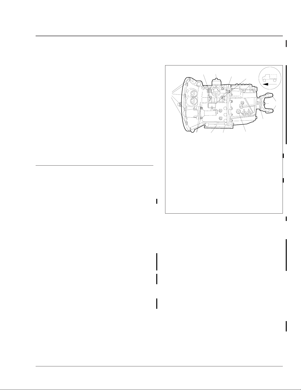
Freightliner AMT3and Mercedes-Benz Automated-Manual
Transmissions
26.03
General Troubleshooting
IMPORTANT: Always use ServiceLink when attempting to diagnose problems with the AGS
(Automated Gear Shift) transmission.
How To Start
To gain a baseline for troubleshooting when there is
no definite problem, when the malfunction is erratic
or intermittent, or to determine the general health of
the electrical system, start with the electrical pre-test
in Subject 301.
In a few cases there will be a definite problem and
no J1587 fault code will be sent (engine will not
crank, no information on gear display, fluid level
fault). For these problems, see the appropriate table
in Subject 301.
Fault Code Guide (MID 130 SIDs)
SID FMI Text Message Failure Reason Procedure
18 02 Prim Selector Erratic The shift lever does not shift gears. See Subject 302.
33 03 MultiPress Ind Short Hi The hydraulic pressure sensor circuit is shorted to power. See Subject 303.
33 04 MultiPress Ind Short Lo The hydraulic pressure sensor circuit is shorted to ground. See Subject 303.
33 05 MultiPress Ind OPEN The hydraulic pressure sensor circuit is open. See Subject 303.
52 05 Hydraulic Sys OPEN The hydraulic pump circuit is open. See Subject 304.
52 07 Hydraulic Sys NoRESPONSE
52 11 Clutch Act Not Known The hydraulic pump temperature is too high. See Subject 304.
55 00 Clutch Act HIGH The clutch is too hot. See Subject 305.
55 07 Clutch Act NoRESPONSE The clutch does not operate properly. See Subject 305.
55 13 Clutch Act Calibrate The clutch needs to be calibrated. See Subject 305.
231 02 SAE J1939 Datalink Erratic The J1939 datalink is not communicating properly. See Subject 306.
231 09 SAE J1939 Datalink UPDATE The J1939 datalink has timed out. See Subject 306.
231 12 SAE J1939 Datalink Bad
251 00 POWER SUPPLY HIGH The power supply voltage is too high. See Subject 307.
251 01 POWER SUPPLY Low The power supply voltage is too low. See Subject 307.
251 05 POWER SUPPLY OPEN
251 14 POWER SUPPLY RSRVD The power supply is not properly grounded. See Subject 307.
253 02 Calibration Memory Erratic The transmission needs to be recalibrated. See Subject 308.
253 12 Calibration Memory Bad The transmission needs to be recalibrated. See Subject 308.
253 13 Calibration Memory Calibrate The transmission needs to be recalibrated. See Subject 308.
253 14 Calibration Memory RSRVD The transmission needs to be recalibrated. See Subject 308.
The hydraulic pressure does not increase even though the
hydraulic pump is activated.
The J1939 datalink is not communicating with the
transmission.
There is no power to the transmission with the engine
running.
But in most cases, the J1587 fault code is the starting point for the troubleshooting procedures. See
Table 1 to find information for SID fault codes. See
Table 2 to find information for PID fault codes.
Before starting any procedures, use ServiceLink to
depressurize the AGS hydraulic system. For detailed
procedures, see Subject 160.
Fault Code Guide
To troubleshoot a given fault code, look up the subject number in Table 1 (for SIDs) and Table 2 (for
PIDs). Follow the procedures for that fault code until
the fault is corrected.
See Subject 304.
See Subject 306.
See Subject 307.
Business Class M2 Workshop Manual, Supplement 20, September 2011 300/1

Freightliner AMT3and Mercedes-Benz Automated-Manual
26.03
Transmissions
General Troubleshooting
Fault Code Guide (MID 130 SIDs)
SID FMI Text Message Failure Reason Procedure
254 04 Controller Short Lo The TCU is shorted to ground. See Subject 309.
254 05 Controller OPEN The TCU has an open circuit. See Subject 309.
254 11 Controller Not Known The TCU AUTO mode software module has an error. See Subject 309.
254 12 Controller Bad The TCU has a hardware problem. See Subject 309.
254 13 Controller Calibrate The TCU has a software memory problem. See Subject 309.
Table 1, Fault Code Guide (SIDs)
Fault Code Guide (MID 130 PIDs)
PID FMI Text Message Failure Reason Procedure
33 02 Erratic The clutch position sensor gives invalid data. See Subject 310.
33 03 Short Hi The clutch position sensor circuit is shorted to power. See Subject 310.
33 04 Short Lo The clutch position sensor circuit is shorted to ground. See Subject 310.
33 05 OPEN The clutch position sensor circuit is open. See Subject 310.
33 14 RSRVD
59 02 Shift FNGR Gear Erratic The shift rod position sensor gives invalid data. See Subject 311.
59 03 Shift FNGR Gear Short Hi The gear position sensor circuit is shorted to power. See Subject 311.
59 04 Shift FNGR Gear Short Lo The gear position sensor circuit is shorted to ground. See Subject 311.
59 05 Shift FNGR Gear OPEN The gear position sensor circuit is open. See Subject 311.
59 14 Shift FNGR Gear RSRVD The gear position sensor gives incorrect resistance readings. See Subject 311.
60 02 Shift FNGR Rail Erratic The rail position sensor circuit gives invalid data. See Subject 312.
60 03 Shift FNGR Rail Short Hi The rail position sensor circuit is shorted to power. See Subject 312.
60 04 Shift FNGR Rail Short Lo The rail position sensor circuit is shorted to ground. See Subject 312.
60 05 Shift FNGR Rail OPEN The rail position sensor circuit is open. See Subject 312.
60 14 Shift FNGR Rail RSRVD The rail position sensor gives incorrect resistance readings. See Subject 312.
64 09 Dir Switch Update
64 11 Dir Switch Not Known
158 00 Volts (BattSw) HIGH The voltage in the ignition power circuit is too high. See Subject 314.
158 01 Volts (BattSw) Low The voltage in the ignition power circuit is too low. See Subject 314.
161 02 In shaft SPEED Erratic The input shaft speed sensor circuit gives invalid data. See Subject 315.
161 03 In shaft SPEED Short Hi The input shaft speed sensor circuit is shorted to power. See Subject 315.
161 04 In shaft SPEED Short Lo The input shaft speed sensor circuit is shorted to ground. See Subject 315.
161 05 In shaft SPEED OPEN The input shaft speed sensor circuit is open. See Subject 315.
161 08 In shaft SPEED Update
The clutch position sensor gives incorrect resistance
readings.
The output shaft speed sensor is not providing accurate
directional information.
The output shaft speed sensor is not providing accurate
directional information.
The input shaft speed sensor circuit is broadcasting an
abnormal frequency.
See Subject 310.
See Subject 313.
See Subject 313.
See Subject 315.
Business Class M2 Workshop Manual, Supplement 20, September 2011300/2

Freightliner AMT3and Mercedes-Benz Automated-Manual
Transmissions
26.03
General Troubleshooting
Fault Code Guide (MID 130 PIDs)
PID FMI Text Message Failure Reason Procedure
162 02 RANGE Selected Erratic The transmission is not properly calibrated. See Subject 316.
163 02 RANGE Attained Erratic The gears do not shift properly. See Subject 316.
191 02 OUTPUT SPEED Erratic
191 05 OUTPUT SPEED OPEN
191 08 OUTPUT SPEED SIGNAL
191 14 OUTPUT SPEED RSRVD The output shaft speed sensor is providing invalid data. See Subject 317.
One or both of the output shaft speed sensor circuits give
invalid data.
One or both of the output shaft speed sensor circuits are
open.
There is no signal coming from one or both output shaft
speed sensors.
Table 2, Fault Code Guide (PIDs)
See Subject 317.
See Subject 317.
See Subject 317.
Business Class M2 Workshop Manual, Supplement 20, September 2011 300/3
Freightliner AMT3and Mercedes-Benz Automated-Manual
Transmissions
IMPORTANT: Always use ServiceLink when attempting to diagnose problems with the automated gear shift (AGS) transmission.
In most cases, the J1587 fault code is the starting
point for the troubleshooting procedures. See Sub-
ject 300 for a list of fault codes and the location of
troubleshooting procedures for each code.
Electrical Pre-Test Instructions
Before starting any procedures, use ServiceLink to
depressurize the AGS hydraulic system. For detailed
procedures, see Subject 160.
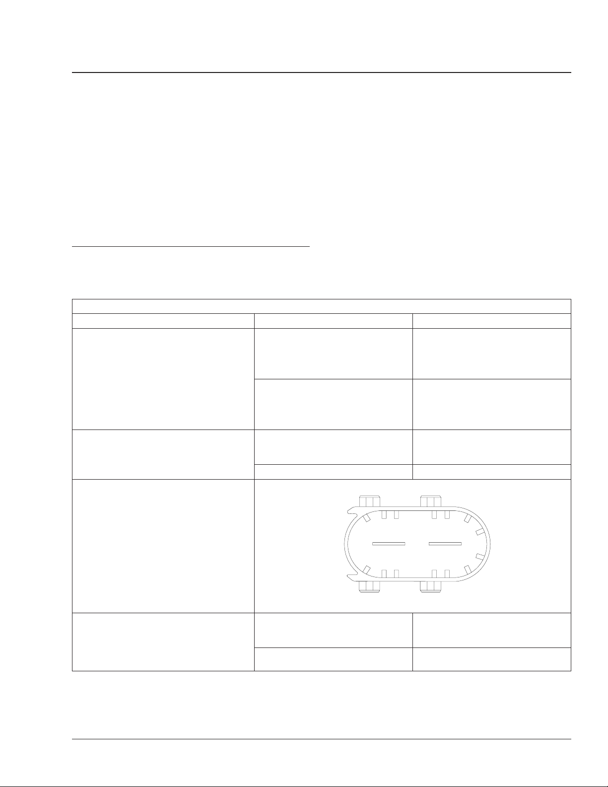
Electrical Pre-Test
Procedure Result Action
Make sure that the selector switch on the
SmartShift lever is set to N. Turn on the
ignition switch to power up the
transmission.
NOTE: If the hydraulic pump starts up with
its characteristic humming noise, this
means the main power cables are OK (see
the steps below to check the X3
connector).
With the ignition switch off, check the
voltage at the battery.
Remove the X3 (electric motor 2-pin)
connector from the transmission control unit
(TCU). Check the electric motor power
circuit.
The current gear indicator does not
power up normally. No fault codes
display.
The current gear indicator goes
through its normal power-up
sequence, ending by displaying "N."
Voltage is less than 11 or greater
than 13 volts.
Voltage is between 11 and 13 volts. Go to the next row in the table.
26.03
Troubleshooting Without Fault Codes
Use the electrical pre-test instructions given in
Table 1 as a baseline for troubleshooting when there
is no definite problem, the malfunction is erratic or
intermittent, or as an informational step to determine
the general health of the electrical system. To record
your findings, a result sheet is provided at the end of
this subject. For locations of serial numbers, see
Fig. 1 and Fig. 2.
Troubleshoot the current gear
indicator. See Table 4.
Turn off the ignition switch and go to
the next row in the table.
Charge or replace the battery. For
battery charging procedures, see
Section 54.12, Subject 150.
2
06/01/2004 f544485
Check for voltage between pin 1 (power
circuit 232) of the X3 connector and the
battery ground terminal.
Business Class M2 Workshop Manual, Supplement 20, September 2011 301/1
Voltage drops more than 0.2 volts
from the voltage measured at the
battery.
Voltage is within 0.2 volts of the
voltage measured at the battery.
X3
1
Repair or replace the wiring as
needed. See Section 54.06, Subject
100.
Go to the next row in the table.
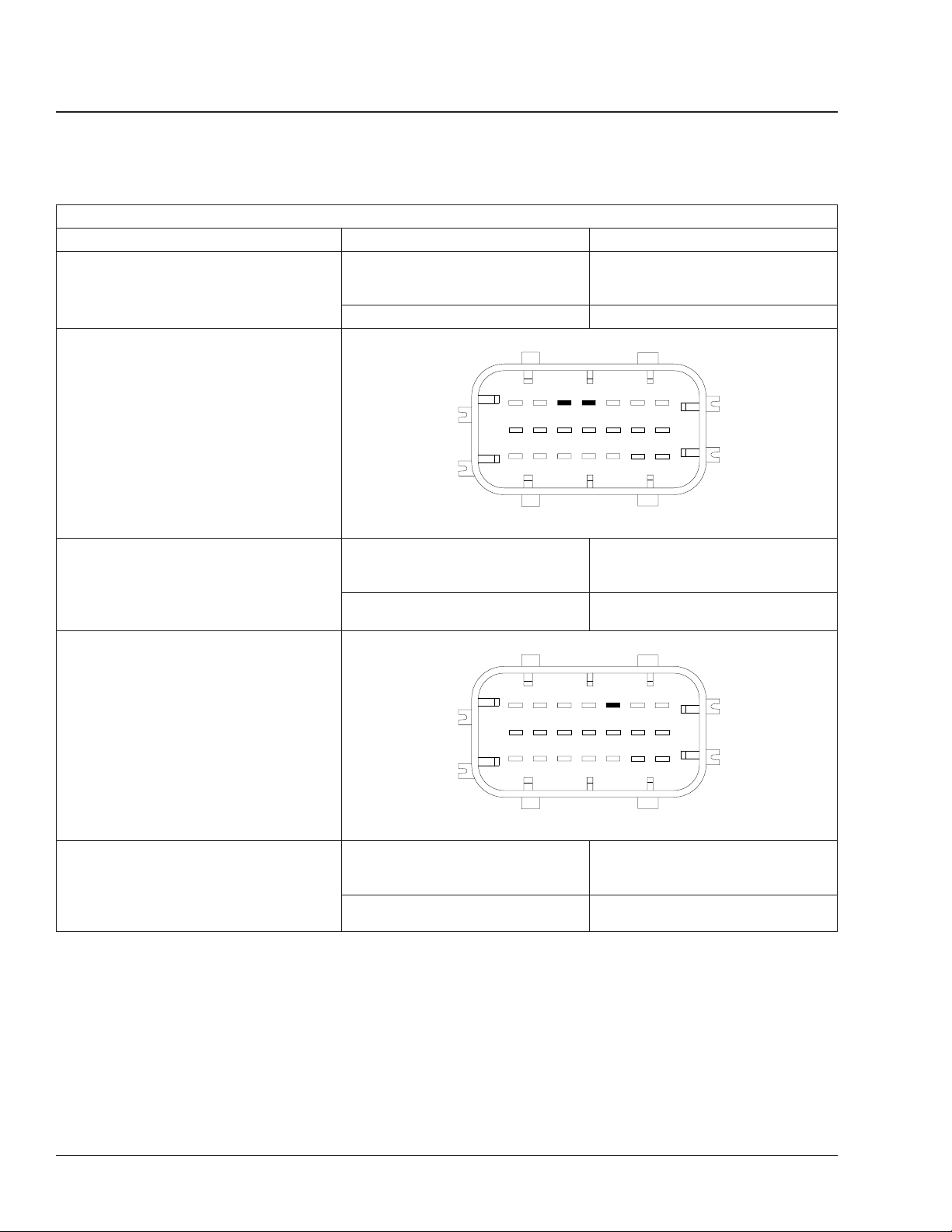
Freightliner AMT3and Mercedes-Benz Automated-Manual
26.03
Troubleshooting Without Fault Codes
Electrical Pre-Test
Procedure Result Action
Check for resistance between pin 2
(ground) of the X3 connector and the
battery ground terminal.
Remove the X1 (vehicle 21-pin) connector
from the transmission control unit (TCU).
Check the battery power circuit.
Resistance is greater than 0.3 ohms. Repair or replace the wiring as
Resistance is 0.3 ohms or less. Go to the next row in the table.
07/16/2004 f544483b
21
20
19
18
17
16
Transmissions
needed. See Section 54.06, Subject
100.
3
15
14
13
12
11
10
X1
6
9
2
5
8
1
4
7
Check for voltage from pins 12 and 15
(battery power circuit 232D) of the X1
connector to the battery ground terminal.
Turn on the ignition switch. Check the
ignition power circuit.
Check for voltage from pin 9 (ignition power
circuit 232E) of the X1 connector to the
battery ground terminal.
Voltage drops more than 0.2 volts
from the voltage measured at the
battery.
Voltage is within 0.2 volts of the
voltage measured at the battery.
18
21
17
20
16
19
07/16/2004 f544483c
Voltage drops more than 0.2 volts
from the voltage measured at the
battery.
Voltage is within 0.2 volts of the
voltage measured at the battery.
Repair or replace the wiring as
needed. See Section 54.06, Subject
100.
Go to the next row in the table.
3
15
14
13
12
11
10
X1
6
9
2
5
8
1
4
7
Repair or replace the wiring as
needed. See Section 54.06, Subject
100.
Go to the next row in the table.
Business Class M2 Workshop Manual, Supplement 20, September 2011301/2
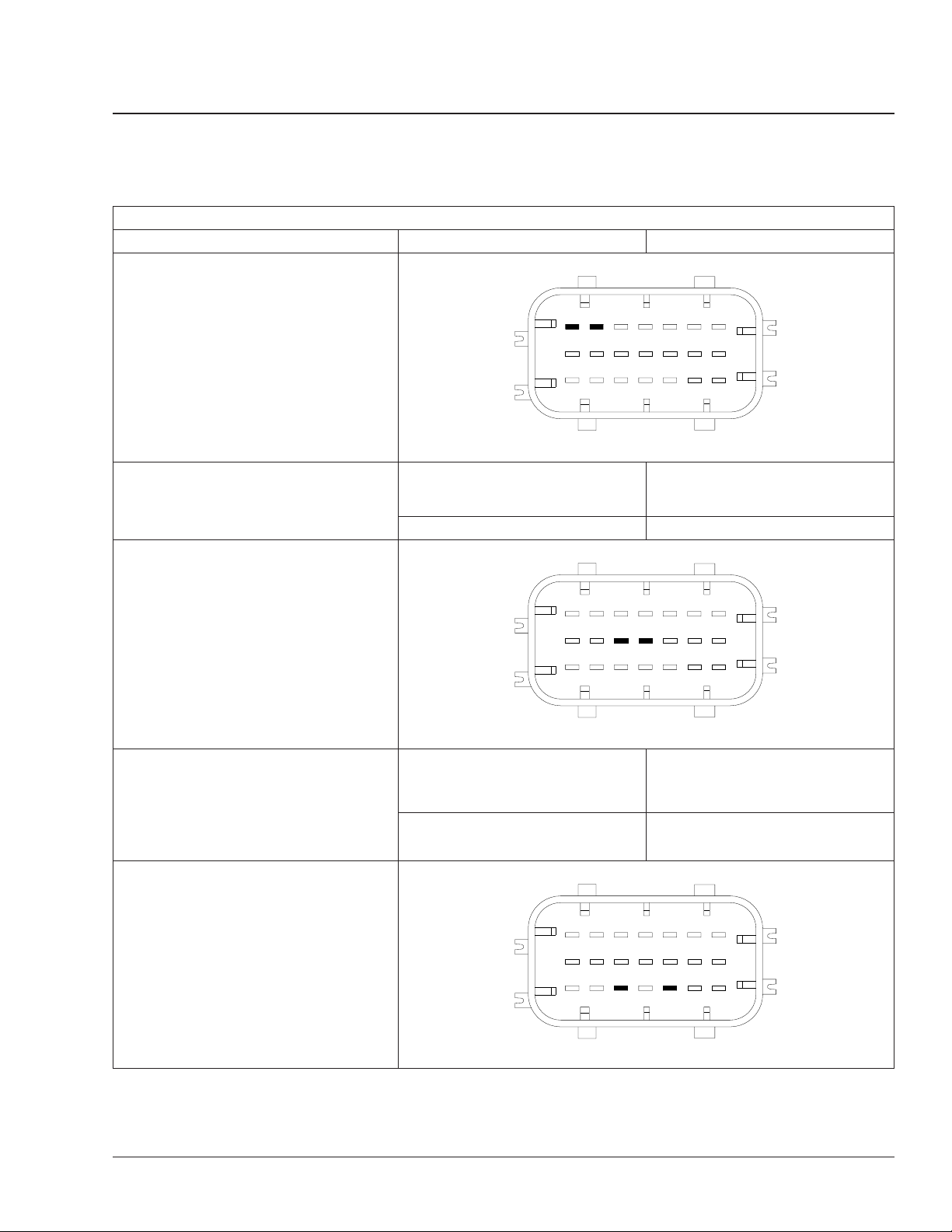
Freightliner AMT3and Mercedes-Benz Automated-Manual
Transmissions
Procedure Result Action
Turn off the ignition switch. Check the
ignition ground circuit.
With the ignition switch off, check for
resistance between pins 18 and 21
(ground) of the X1 connector and the
battery ground terminal.
Turn off the ignition switch. Check the
J1587 wiring.
26.03
Troubleshooting Without Fault Codes
Electrical Pre-Test
3
12
15
18
21
11
14
17
20
10
13
16
19
07/21/2004 f544483d
Resistance is greater than 0.3 ohms. Repair or replace the wiring as
Resistance is 0.3 ohms or less. Go to the next row in the table.
X1
6
9
2
5
8
1
4
7
needed. See Section 54.06, Subject
100.
Check for DC voltage from pins 11 and 14
(J1587 datalink) of the X1 connector to the
battery ground terminal.
NOTE: If the meter cannot display the
rapidly shifting DC voltage, measure AC
voltage instead.
Turn off the ignition switch. Check the
J1939 wiring.
15
18
21
14
17
20
13
16
19
07/21/2004 f544483e
Voltage is less than 1 or more than 4
volt(s) for DC (less than 1 or more
than 3 for AC).
Voltage is between 1 and 4 volts for
DC (1–3 volts AC).
15
18
21
14
17
20
13
16
19
07/16/2004 f544483a
3
12
11
10
X1
12
11
10
X1
6
9
2
5
8
1
4
7
Troubleshoot the J1587 datalink.
Go to the next row in the table.
3
6
9
2
5
8
1
4
7
Business Class M2 Workshop Manual, Supplement 20, September 2011 301/3
Freightliner AMT3and Mercedes-Benz Automated-Manual
26.03
Troubleshooting Without Fault Codes
Electrical Pre-Test
Procedure Result Action
With the ignition switch off, remove the X1
connector from the TCU and check for
resistance between pins 7 and 13 (J1939
datalink).
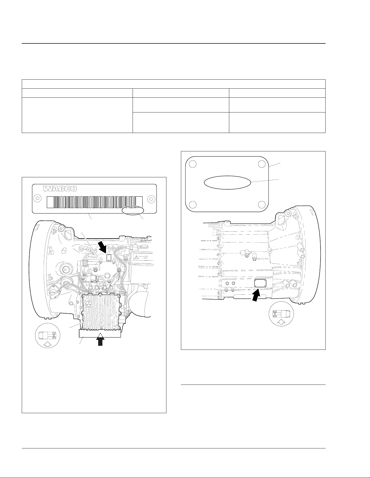
NOTE: To see the identification plate on the
TCU it may be necessary to remove the splash
guard.
20 0 3 0 0 4
0 0 6 00 0 14 7 7
Resistance is less than 55 or greater
than 65 ohms.
Resistance is between 55 and 65
ohms.
Table 1, Electrical Pre-Test
0005255 90 32 6 09 7 0A
Troubleshoot the J1939 datalink. See
Freightliner Service Bulletin 54-133.
The vehicle has passed the electrical
pre-test. Troubleshoot active fault
codes, if any.
DaimlerChrysler
Bez: G 60−6
IdNr 715053 123456
Code C07−00036−031
M−C
Var. 041962
Transmissions
1
2
3
5
1
2
10/05/2006
NOTE: The TCU and X-Y Actuator each have their own
WABCO identification plate (arrows) with unique serial
numbers.
1. TCU (Transmission
Control Unit)
2. Splash Guard
3. WABCO
Identification Plate
Fig. 1, Serial Numbers for TCU and X-Y Actuator
4. Serial Number
5. X-Y Actuator
4
f261384
DaimlerChrysler
Bez: G 60−6
IdNr 715053 123456
Code C07−00036−031
M−C
Var. 041962
10/05/2006
1. Transmission
Identification Plate
Fig. 2, Transmission Serial Number
2. Serial Number
f261383
Troubleshooting Tables, No
Fault Codes
In a few cases there will be a definite problem and
no J1587 fault code will be sent.
• If the engine will not crank and there are no
transmission fault codes, see Table 2.
Business Class M2 Workshop Manual, Supplement 20, September 2011301/4

Freightliner AMT3and Mercedes-Benz Automated-Manual
Transmissions
Transmission Range Faults (PID 162 and 163)
Transmission Range Faults
Transmission Range-Selected
Faults (PID 162)
There is one transmission range-selected fault covered in these procedures.
• For PID 162, FMI 02, see Table 1 for proce-
dures.
PID 162, FMI 02—The Transmission Is Not Properly Calibrated
Failure Reason:
• The gears are caught in an intermediate position.
• The transmission software does not allow shifting.
Problem Procedure Result Action
There are other
active transmission
faults.
The transmission
needs to be
recalibrated.
Check for other MID 130 fault codes. Other fault codes
Complete a learning procedure using either ServiceLink or
the SmartShift control.
To complete a learning procedure using the SmartShift
control:
1. Ensure that the parking brake is set.
2. With the ignition turned off, pull and hold the SmartShift
control toward steering wheel.
NOTE: The SmartShift control must be kept in this position
until the gear display clears at the end of the procedure.
3. Turn on the ignition. The normal warm up procedure will
initiate and an ’X’ will display on the current gear indicator.
Your transmission may be heard shifting.
4. Wait until the current gear indicator displays an ’N’
(about 30 seconds) and an audible alert sounds. Start the
engine within 10 seconds of the audible alert.
5. The engine will raise a few rpm, then fall back to idle,
and an audible alert will sound. Turn off the engine within
10 seconds of audible alert. When the gear display clears,
this procedure is complete.
NOTE: If during this procedure an ’SM’ or ’X’ (after the
warm up procedure) appears in the gear display, stop, turn
off the ignition, and wait for the gear display to go dark.
Then start over. This may need to be repeated several
times.
Table 1, The Transmission Is Not Properly Calibrated
Transmission Range-Attained
Faults (PID 163)
There is one transmission range-attained fault covered in these procedures.
• For PID 163, FMI 02, see Table 2 for proce-
dures.
are active.
No other fault
codes are active.
The fault is no
longer active.
The fault is still
active.
26.03
Troubleshoot the
other active fault
codes.
Go to the next step
in the table.
No further action is
needed.
Contact
Freightliner
Technical Service
Support.
Business Class M2 Workshop Manual, Supplement 20, September 2011 316/1

Freightliner AMT3and Mercedes-Benz Automated-Manual
26.03
Transmission Range Faults (PID 162 and 163)
PID 163, FMI 02—The Gears Do Not Shift Properly
Failure Reason:
• There is a defect in the TCU.
• There is a defect in the speed sensor.
• There is a defect in the actuator.
• The transmission software is not properly programmed.
• The datalink does not recognize the transmission type.
Problem Procedure Result Action
There are other
active transmission
faults.
There is a
transmission
software problem.
There is component
damage in the
transmission.
Check for other MID 130 fault codes. Other fault codes are
Using the ServiceLink diagnostics template,
view the different gear positions, check that
the clutch opens and closes, and that the
x-y actuator moves from reverse, 1st, and
2nd gears.
Do a visual inspection of the x-y actuator,
the hydraulic system, and the transmission
shift system.
Table 2, The Gears Do Not Shift Properly
active.
No other fault codes are
active.
The x-y actuator
responds properly and
the fault clears.
The fault is still active. Go to the next step in the
Damaged components
are found.
No damaged
components are found.
Troubleshoot the other
active fault codes.
Go to the next step in the
table.
No further action is needed.
table.
Contact Mercedes-Benz
Transmissions Service
Support with the AGS
codes and results of the
electrical pre-test.
NOTE: One hour of
troubleshooting time is
alloted for printing the AGS
codes and completing the
electrical pre-test.
1. Using ServiceLink, print
the AGS codes (130).
2. Complete the electrical
pre-test result sheet in
Subject 301.
3. With the results, contact
Mercedes-Benz
Transmissions Service
Support by fax
(503.961.8435), email
(MBTServiceSupport@
Freightliner.com), or phone
(503.745.4965 or
503.745.4988).
Transmissions
Business Class M2 Workshop Manual, Supplement 20, September 2011316/2
Freightliner AMT3and Mercedes-Benz Automated-Manual
Transmissions
26.03
Output Shaft Speed Sensor Faults (PID 191)
Output Shaft Speed Sensor
Faults (PID 191)
There are four output shaft speed sensor faults covered in these procedures. One troubleshooting procedure is used to correct FMI 02, 05, and 08. A
separate procedure is used for FMI 14.
PID 191, FMI 02, 05, 08—The Output Shaft Speed Sensor Circuit Gives Invalid Data, Is Open, or Not Broadcasting
Failure Reason:
• The TCU has a hardware prob-
lem.
• The sensor is mounted too loose
(air gap too big).
• The sensor connectors are dam-
aged or bent.
• The wiring harness has had an
electrical failure.
• Either one of the sensors or the
TCU has failed.
Procedure Results Action
Turn on the ignition switch and wait for
the current gear display to power up.
Remove both output shaft speed
sensors. Reinstall and tighten the sensor
28 lbf·ft (38 N·m).
Turn off the ignition switch and wait for
the current gear display to power down.
Remove both sensor connectors and
visually inspect the pins.
Check the upper sensor for continuity:
(1) X2 connector pin 1 to sensor pin 2;
(2) X2 connector pin 15 to sensor pin 1;
(3) X2 connector pin 14 to sensor pin 4.
Check the lower sensor for continuity:
(1) X2 connector pin 1 to sensor pin 2;
(2) X2 connector pin 15 to sensor pin 1;
(3) X2 connector pin 9 to sensor pin 3.
Check all four pins of each sensor
connector for voltage and for continuity
to ground.
Fault code SID 254, FMI 12 is active. Go to Subject 309 and troubleshoot
SID 254, FMI 12 is not active. Go to the next row in the table.
The fault clears after a test drive. No further action needed.
The fault remains active. Go to the next row in the table.
The connector pins are damaged or
bent.
There is no damage to either
connector.
There is an open circuit. Replace the transmission wiring
The wiring is OK. Go to the next row in the table.
There is an open circuit. Replace the transmission wiring
The wiring is OK. Go to the next row in the table.
Voltage or continuity is found. Replace the transmission wiring
There is zero voltage and no continuity. Go to the next row in the table.
a Signal
07/16/2004 f544484k
• For PID 191, FMI 02, 05, and 08 see Table 1
for procedures and pin identification.
• For PID 191, FMI 14, see Table 2 for proce-
dures.
1
4
2
5
3
6
X2
SID 254, FMI 12.
Repair or replace the damage.
Go to the next row in the table.
harness (see Subject 180).
harness (see Subject 180).
harness (see Subject 180).
13
7
10
14
11
8
15
9
12
Business Class M2 Workshop Manual, Supplement 20, September 2011 317/1
Freightliner AMT3and Mercedes-Benz Automated-Manual
26.03
Transmissions
Output Shaft Speed Sensor Faults (PID 191)
PID 191, FMI 02, 05, 08—The Output Shaft Speed Sensor Circuit Gives Invalid Data, Is Open, or Not Broadcasting
Failure Reason:
• The TCU has a hardware prob-
lem.
• The sensor is mounted too loose
(air gap too big).
• The sensor connectors are dam-
aged or bent.
• The wiring harness has had an
electrical failure.
• Either one of the sensors or the
TCU has failed.
Procedure Results Action
Using a sensor known to be good,
replace each sensor in turn (see
Subject 120 for procedures).
Table 1, The Output Shaft Speed Sensor Circuit Gives Invalid Data, Is Open, or Not Broadcasting a Signal
The fault becomes inactive. No further action needed.
The fault is still active. Contact Mercedes-Benz Transmissions
a Signal
1
4
2
5
3
6
07/16/2004 f544484k
X2
Service Support with the AGS codes
and results of the electrical pre-test.
NOTE: One hour of troubleshooting
time is alloted for printing the AGS
codes and completing the electrical
pre-test.
1. Using ServiceLink, print the AGS
codes (130).
2. Complete the electrical pre-test
result sheet in Subject 301.
3. With the results, contact MercedesBenz Transmissions Service Support
by fax (503.961.8435), email
(MBTServiceSupport@
Freightliner.com), or phone
(503.745.4965 or 503.745.4988).
13
7
10
14
11
8
15
9
12
PID 191, FMI 14—The Output Shaft Speed Sensor Is Providing Invalid Data
Failure Reason
• The antilock brake system (ABS) is not broadcasting wheel speed data.
• There is a defective output shaft speed sensor.
Procedure Result Action
Check for other PID 191 fault codes. Other PID 191 fault codes
are active.
No other PID 191 fault
codes are active.
Business Class M2 Workshop Manual, Supplement 20, September 2011317/2
Troubleshoot PID 191. See
Table 1.
Go to the next step in the
table.

Freightliner AMT3and Mercedes-Benz Automated-Manual
Transmissions
Output Shaft Speed Sensor Faults (PID 191)
PID 191, FMI 14—The Output Shaft Speed Sensor Is Providing Invalid Data
Failure Reason
• The antilock brake system (ABS) is not broadcasting wheel speed data.
• There is a defective output shaft speed sensor.
Procedure Result Action
Check for active fault codes in MID 136 (ABS). Active MID 136 fault codes
are found.
Table 2, The Output Shaft Speed Sensor Is Providing Invalid Data
26.03
Troubleshoot the ABS system
(see the applicable section in
Group 42).
Business Class M2 Workshop Manual, Supplement 20, September 2011 317/3
Freightliner AMT3and Mercedes-Benz Automated-Manual
Transmissions
For a schematic of the AGS transmission wiring behind the X2 (transmission) connector, see Fig. 1. For
a schematic of the AGS transmission wiring behind
the X1 (main vehicle) and X3 (electric motor) connectors, see drawing G06-49466.
Input Shaft Speed
Sensor
2
13
11 9 14
11
Output Shaft Speed Sensor
3
SS
X2 Connector
For a list of special tools, see Table 1.
(9:00 position)
22
GND GND
+12V +12V
Output Shaft Speed Sensor
(11:00 position)
1
15
26.03
Specifications
1
02/01/2005
3
111 1
Gear Position Sensor
(Front)
2
Rail Position Sensor
(Rear)
67
10 12
222
Clutch Position Sensor Fluid Level Sensor
45
2
(Pentosin)
Circuit is closed when full
f544529
Fig. 1, AGS Transmission Wiring, X2 Connector
Special Tools for AGS Transmission
Tool Description Manufacturer Part Number
Accumulator Torque Adaptor Kent-Moore J-47291
f580381
Low-Pressure Hose Disconnect Tool Kent-Moore J-47202
f580379a
Business Class M2 Workshop Manual, Supplement 20, September 2011 400/1
Freightliner AMT3and Mercedes-Benz Automated-Manual
26.03
Specifications
Tool Description Manufacturer Part Number
Transmissions
Special Tools for AGS Transmission
High-Pressure Line Disconnect Tool Kent-Moore J-47201
f580379
Shift Finger Alignment Fork Kent-Moore J-47204
f580380
Shift Mechanism End Guide Kent-Moore J-47203
f580382
Table 1, Special Tools for AGS Transmission
For transmission installation torque values, see
Table 2.
Transmission Installation Torque Values
Description Size Class Torque: lbf·ft (N·m)
Midship Bearing Bracket Capscrews 3/4–11 — 91 (123)
Power Takeoff Unit (PTO) Mounting Capscrews M10 10.9 43 (58)
Transmission Fluid Drain Plug M24 — 42 (57)
Transmission Fluid Fill Plug M24 — 42 (57)
Transmission Mounting Bolts M10 x 1.5 8.8 33 (45)
U-Joint End Cap Bolts
Table 2, Transmission Installation Torque Values
For AGS assembly torque values, see Table 3.
AGS Assembly Torque Values
Description Size Torque: lbf·ft (N·m) Torque: lbf·in (N·cm)
Accumulator Hydraulic Fitting M30 59 (80) —
X-Y Actuator Mounting Capscrews M8 17 (23) —
3/8–24 — 50 (68)
1/2–20 — 110 (149)
Business Class M2 Workshop Manual, Supplement 20, September 2011400/2

Freightliner AMT3and Mercedes-Benz Automated-Manual
Transmissions
26.03
Specifications
AGS Assembly Torque Values
Description Size Torque: lbf·ft (N·m) Torque: lbf·in (N·cm)
AGS Central Unit Mounting Capscrews M8 17 (23) —
Clutch Actuator Hydraulic Fittings M30 37 (50) —
Clutch Actuator Mounting Capscrews M8 17 (23) —
Pressure-Limiting Valve Adjusting Screw M6 — 63–71 (700–800)
Reservoir Base Fasteners M8 11 (15) —
Reservoir Top Fasteners M6 — 71 (800)
Rotational Speed (RPM) Sensors — 28 (38) —
Shift Rod Setscrew M12 22 (30) —
Transmission Control Unit (TCU) Mounting Screws M8 — 44–53 (500–600)
TCU Splash Guard Mounting Capscrews M8 17 (23) —
Table 3, AGS Assembly Torque Values
For AGS transmission gear ratios, see Table 4.
AGS Transmission Gear Ratios
Model Gear Ratio
MBT520-6DA
MBT660-6OA
Table 4, AGS Transmission Gear Ratios
For a list of proprietary fault codes viewable on ServiceLink, see Table 5.
1 9.201
2 5.230
3 3.145
4 2.034
5 1.374
6 1.000
R 8.649
1 6.700
2 3.810
3 2.290
4 1.480
5 1.000
6 0.730
R 6.290
AGS Proprietary Fault Codes (J1708)
Fault Code Description
3000109 High voltage supply voltage—external (connector X1/12 and X1/15)
Business Class M2 Workshop Manual, Supplement 20, September 2011 400/3

Freightliner AMT3and Mercedes-Benz Automated-Manual
26.03
Specifications
AGS Proprietary Fault Codes (J1708)
Fault Code Description
3000113 High voltage ignition key line—external (connector X1/9)
3000209 Low voltage supply voltage—external (connector X1/12 and X1/15)
3000213 Low voltage ignition key line—external (connector X1/9)
3001210 EEPROM parameter values error—internal
3001510 Clutch displacement control module parameter error—internal
3001781 Clutch calibration offset off limit—internal
3002009 Open load supply voltage—external (connector X1/12 and X1/15)
3002016 Open load/Short circuit VCC temperature sensor circuit board—internal
3002017 Open load/Short circuit VCC temperature sensor pump—internal
3002116 Short circuit GND temperature sensor circuit board—internal
3002117 Short circuit GND temperature sensor pump—internal
3002214 Short circuit VCC peripherals supply—external (connector X2/15)
3003001 EBC1 message timeout—external (J1939)
3003101 EEC1 message timeout—external (J1939)
3003201 EEC2 message timeout—external (J1939)
3003301 EEC3 message timeout—external (J1939)
3003401 ERC1 message timeout—external (J1939)
3003501 Wheel speed information message timeout—external (J1939)
3003601 CruiseControl (VCU) message timeout—external (J1939)
3003701 CruiseControl (bulkhead) message timeout—external (J1939)
3003801 Engine configuration message timeout—external (J1939)
3003901 Retarder configuration message timeout—external (J1939)
3004001 Component identification message timeout—external (J1939)
3004101 PTO information message timeout—external (J1939)
3006101 Incorrect engine data—external (J1939)
3006201 Timeout converted engine data for clutch module (low priority)—internal
3006701 Incorrect retarder data—external (J1939)
3006801 Incorrect ABS data—external (J1939)
3006901 Incorrect internal data—internal
3007001 Incorrect clutch module data—internal
3007101 Incorrect automated gear shift module data—internal
3007201 Incorrect internal data—internal
3008881 Clutch overload—internal
3009280 Plausibility error actual transmission gear ratio—internal
3009710 Test software—internal
3009810 Test electronic—internal
Transmissions
Business Class M2 Workshop Manual, Supplement 20, September 2011400/4

Freightliner AMT3and Mercedes-Benz Automated-Manual
Transmissions
AGS Proprietary Fault Codes (J1708)
Fault Code Description
3009910 Test bench mode activated—internal
3010390 Automatic module: signal group cruise control / retarder—internal
3010690 Automatic module: signal output speed—internal
3010790 Automatic module: signal group MR—internal
3010890 Automatic module: signal group gear ratio—internal
3010990 Automatic module: learning values engine—internal
3011081 Plausibility error intended clutch position can not be reached within specified time—internal
3011090 Automatic module: learning values transmission—internal
3011310 Clutch calibration data missing/error—internal
3011410 Clutch parameter error—internal
3011590 Automatic module: signal group shifting time—internal
3011690 Automatic module: signal group ABS—internal
3011790 Automatic module: signal group pedal activation—internal
3011890 Automatic module: signal group lever—internal
3011990 Automatic module: error target system—internal
3012014 Open load peripherals supply—external (connector X2/15)
3012019 Plausibility error valve relay V-V2 on—internal
3012035 Open load power stage solenoid valve (clutch open 1)—internal
3012036 Open load power stage solenoid valve (clutch open 2)—internal
3012037 Open load power stage solenoid valve (clutch close 1)—internal
3012038 Open load power stage solenoid valve (clutch close 2)—internal
3012050 Open load speed sensor transmission output (DZ1)—external (connector X2/14)
3012051 Open load speed sensor transmission input—external (connector X2/11)
3012052 Open load speed sensor transmission output (D3)—external (connector X2/9)
3012090 Automatic module: system identification gearshift module—internal
3012114 Short circuit to GND peripherals supply—external (connector X2/15)
3012118 Plausibility error valve relay V-V1 off—internal
3012119 Plausibility error valve relay V-V2 off—internal
3012136 Short circuit GND power stage solenoid valve (clutch open 2)—internal
3012138 Short circuit GND power stage solenoid valve (clutch close 2)—internal
3012151 Short circuit GND speed sensor transmission input—external (connector X2/11
3012251 Short circuit VCC speed sensor transmission input—external (connector X2/11)
3012461 Hydraulic level too low external—external
3016201 Timeout converted engine data for clutch module (medium priority)—internal
3016401 Timeout driving direction information—internal
3016501 Timeout internal communication shift module to clutch module (medium priority)—internal
26.03
Specifications
Business Class M2 Workshop Manual, Supplement 20, September 2011 400/5

Freightliner AMT3and Mercedes-Benz Automated-Manual
26.03
Specifications
AGS Proprietary Fault Codes (J1708)
Fault Code Description
3018681 Plausibility error clutch open request while inlet valves are closed—internal
3018781 Plausibility error clutch open request while outlet valves are closed—internal
3019480 Plausibility error driving direction—internal
3019621 SmartShift lever data invalid—external (connector X1/8, X1/11, X1/14)
3019650 Tooth signal interruption speed sensor transmission output (DZ1)—external (connector X2/14)
3019651 Tooth signal interruption speed sensor transmission input—external (connector X2/11)
3019652 Tooth signal interruption speed sensor transmission output (D3)—external (connector X2/9)
3020110 High voltage distance sensor supply—internal
3020111 Power supply high voltage—external (connector X3/1)
3020210 Low voltage distance sensor supply—internal
3020211 Power supply low voltage—external (connector X3/1)
3021010 Flash checksum error—internal
3021110 EEPROM calibration values error—internal
3021610 Clutch displacement offset failure—internal
3022011 Supply voltage open load—external (connector X3/1)
3022012 Open load GND connection—external (connector X1/18 and X1/21)
3022015 Open load pressure sensor signal—internal
3022018 Plausibility error valve relay V-V1 on—internal
3022020 Open load GND pump motor—external (connector X3/2)
3022030 Open load power stage solenoid valve (selection direction R)—internal
3022031 Open load power stage solenoid valve (selection direction 5/6)—internal
3022032 Open load power stage solenoid valve—internal
3022033 Open load power stage solenoid valve (gear direction 1,3,5)—internal
3022034 Open load power stage solenoid valve (pressure regulation)—internal
3022041 Open load distance sensor (gear)—internal
3022042 Open load distance sensor (selection)—internal
3022044 Open load distance sensor (clutch)—internal
3022060 Open loop power stage pump motor—internal
3022115 Short circuit GND pressure sensor signal—internal
3022130 Short circuit GND power stage solenoid valve (selection direction R)—internal
3022131 Short circuit GND power stage solenoid valve (selection direction 5/6)—internal
3022132 Short circuit GND power stage solenoid valve (gear direction R,2,4,6)—internal
3022133 Short circuit GND power stage solenoid valve (gear direction 1,3,5)—internal
3022134 Short circuit GND power stage solenoid valve (pressure regulation)—internal
3022135 Short circuit GND power stage solenoid valve (clutch open 1)—internal
3022137 Short circuit GND power stage solenoid valve (clutch close 1)—internal
Transmissions
Business Class M2 Workshop Manual, Supplement 20, September 2011400/6

Freightliner AMT3and Mercedes-Benz Automated-Manual
Transmissions
AGS Proprietary Fault Codes (J1708)
Fault Code Description
3022141 Short circuit GND distance sensor (gear)—internal
3022142 Short circuit GND distance sensor (selection)—internal
3022144 Short circuit GND distance sensor (clutch)—internal
3022160 Short circuit GND power stage pump motor—internal
3022215 Short circuit VCC pressure sensor signal—internal
3022241 Short circuit VCC distance sensor (gear)—internal
3022242 Short circuit VCC distance sensor (selection)—internal
3022244 Short circuit VCC distance sensor (clutch)—internal
3022317 Over temperature power stage pump motor—internal
3022590 Automatic module: no signal vehicle speed—internal
3022690 Automatic module: signal group MR (high priority)—internal
3022790 Automatic module: signal group gear ratio (high priority)—internal
3022890 Automatic module: learning values engine (high priority)—internal
3022990 Automatic module: learning values transmission (high priority)—internal
3024341 Erratic distance sensor (gear)—internal
3024342 Erratic distance sensor (selection)—internal
3024344 Erratic distance sensor (clutch)—internal
3024441 Wrong coil resistance value distance sensor (gear)—internal
3024442 Incorrect coil resistance value distance sensor (selection)—internal
3024444 Incorrect coil resistance value distance sensor (clutch)—internal
3024610 Timeout displacement sensor value—internal
3026001 CAN bus off—external (connector X1/13 and X1/7)
3026301 Timeout converted engine data for clutch module (high priority)—internal
3026501 Timeout internal communication shift module to clutch module (high priority)—internal
3027401 No J1939 communication—internal / external (connector X1/13 and X1/7)
3027501 Timeout internal communication shift module to clutch module (high priority)—internal
3028581 Clutch displacement control failure—internal
3029180 No calculation of redundant transmission output speed—internal
3029380 Incorrect transmission type—internal
3029580 Plausibility error pressure build up—internal
Table 5, AGS Proprietary Fault Codes (J1708)
26.03
Specifications
For a list of learning procedure errors, see Table 6.
Learning Procedure Errors
Error Description
56 Offset of clutch position out of range
Business Class M2 Workshop Manual, Supplement 20, September 2011 400/7

Freightliner AMT3and Mercedes-Benz Automated-Manual
26.03
Specifications
Error Description
57 Offset of pressure modulation valve out of range
58 Gear position "neutral" out of range
61 Low gear position out of range
62 High gear position out of range
63 Low select position out of range
66 High select position out of range
68 Valve or sensor failure
69 Vehicle is moving
70 Low voltage or high voltage
71 Clutch open/closed
72 Stalk lever position changed during learning procedure
73 Type of gear box invalid
74 Park brake not activated
76 Engine is running
77 Engine torque invalid or out of range
78 Engine was not started in time
80 Accelerator pedal not idle
82 Countershaft speed not zero
Transmissions
Learning Procedure Errors
Table 6, Learning Procedure Errors
Business Class M2 Workshop Manual, Supplement 20, September 2011400/8

Mercedes-Benz Manual Transmission
26.04
General Information
General Information
The Mercedes-Benz transmission (MBT) is offered in
two 6-speed models:
• MBT520S-6D, direct drive, 520 lb·ft torque rating
• MBT660S-6O, overdrive, 660 lb·ft torque rating
The gear case holds 9.5 quarts (9.0 liters) of oil. MobilTrans SHC
Both models are fully synchronized for reduced shifting effort. Equipped with six forward speeds and one
reverse speed, both models show a particularly large
overall ratio between low and top gear. See Specifi-
cations, 400 for gear ratios for each model.
To reduce fluid change intervals and to increase
bearing life, MBT transmissions are designed with
"clean" bearings. These bearings have covers on
both sides. They cannot be damaged by the wear
particles that accumulate in the fluid. The geometry
of the gear teeth has been optimized to provide lownoise operation and extended gear life.
The bell housing has been designed around standard
SAE bolt patterns. SAE2 is standard on both
MBT660S-6O and MBT520S-6D models.
Other features of the MBT transmissions include:
• Light metal gear cases with integrated bell
housings;
• Low installation height (the shift interface is
positioned laterally);
• Double synchronization from 1st gear to 4th
gear;
• Electronic vehicle speed sensor;
• Longer oil change intervals;
• Full range of PTO units available.
Each model requires a hydraulic clutch system. No
clutches with manual control can be installed for use
on MBT transmissions. With the hydraulic system
installed, the clutch linkage is self-adjusting.
The hydraulic clutch system consists of the following
parts:
• Hydraulic fluid reservoir;
• Clutch pedal unit;
• Master cylinder;
®
DC is the approved oil.
• Slave cylinder;
• Hydraulic lines connecting the various parts of
the system.
The MBT transmission removal and installation procedures have been moved to Subject 100 from their
previous location in Section 26.00.
The teardown procedures included in this section
also apply to the AGS automated transmission, with
slight changes which are indicated at appropriate
places in the procedures. If it is necessary to tear
down the AGS transmission, be sure to remove the
AGS assembly before proceeding. See Sec-
tion 26.03, Subject 200 for procedures.
On all transmissions, disassembly of the transmission main shaft is not recommended except when it
is necessary to check for synchronizer wear. Disassembly of the countershaft is not recommended in
any case.
It is important to check main shaft end play if either
gear case half, the main shaft bearings, or the input
shaft is replaced. For detailed procedures, see Sub-
ject 250.
To prevent premature tool wear, use extreme pressure lubricant such as Kent-Moore J 23444-A or
equivalent on tool threads and at all friction and contact points.
Business Class M2 Workshop Manual, Supplement 10, September 2006 050/1
Mercedes-Benz Manual Transmission
Transmission Removal and Installation
Removal
1. Park the vehicle on a level surface. Shut down
the engine, set the parking brake, and chock the
rear tires.
2. Drain the transmission fluid. See Fig. 1 for the
location of the drain plug.
1
26.04
1
2
3
05/22/2001
NOTE: The transmission is shown from the left-hand
side.
1. Transmission
2. Fill Plug
Fig. 1, Transmission Drain and Fill Plugs
3
3. Drain Plug
2
f261102
3. Disconnect the driveshaft from the transmission.
3.1 Support the midship bearing.
3.2 Remove the bolts from the U-joint end
caps and slide the front of the driveshaft
out of the transmission output yoke. See
Fig. 2.
3.3 Remove the midship bearing bracket. See
Fig. 3.
3.4 Support the disconnected driveshaft and
chain it out of the way. See Fig. 4.
4. Remove the shift lever from the transmission.
4.1 Before removing the shift lever, place the
transmission in high gear.
4.2 Remove the four screws from the retaining
ring around the shift lever boot. See
Fig. 5. Remove the ring and the boot.
4.3 Remove the head of the shift lever from
the transmission. See Fig. 6. For ease of
06/05/2001
1. Transmission
2. Output Yoke
3
01/28/99
1. Midship Bracket
2. Mounting Bolt
Fig. 3, Midship Bearing Bracket
3. Driveshaft
Fig. 2, Output Yoke
2
1
3. Driveshaft
f261005
3
f261006
installation, mark the head of the shift lever and the attachment point on the transmission with a paint pen.
5. Remove the fuel lines and the fuel line standoff
bracket from the transmission. See Fig. 7.
Business Class M2 Workshop Manual, Supplement 8, September 2005 100/1
26.04
Mercedes-Benz Manual Transmission
Transmission Removal and Installation
1
1
2
3
4
01/28/99
07/14/94
Fig. 4, Supporting the Driveshaft
Fig. 5, Shift Lever and Boot
f261007
f260074a
06/06/2001
1. Shift Lever
2. Shift Lever Mounting Bolt
3. Thick Washer
4. Head of Shift Lever
Fig. 6, Shift Lever Connection
6. Disconnect the electrical connectors for the reverse gear switch and the optional starter lock
switch (if installed). Mark with a paint pen for
ease of installation.
f261108
WARNING
Do not press down on the clutch pedal after removing the slave cylinder. Hydraulic brake fluid
may squirt out, causing personal injury and damage to the vehicle.
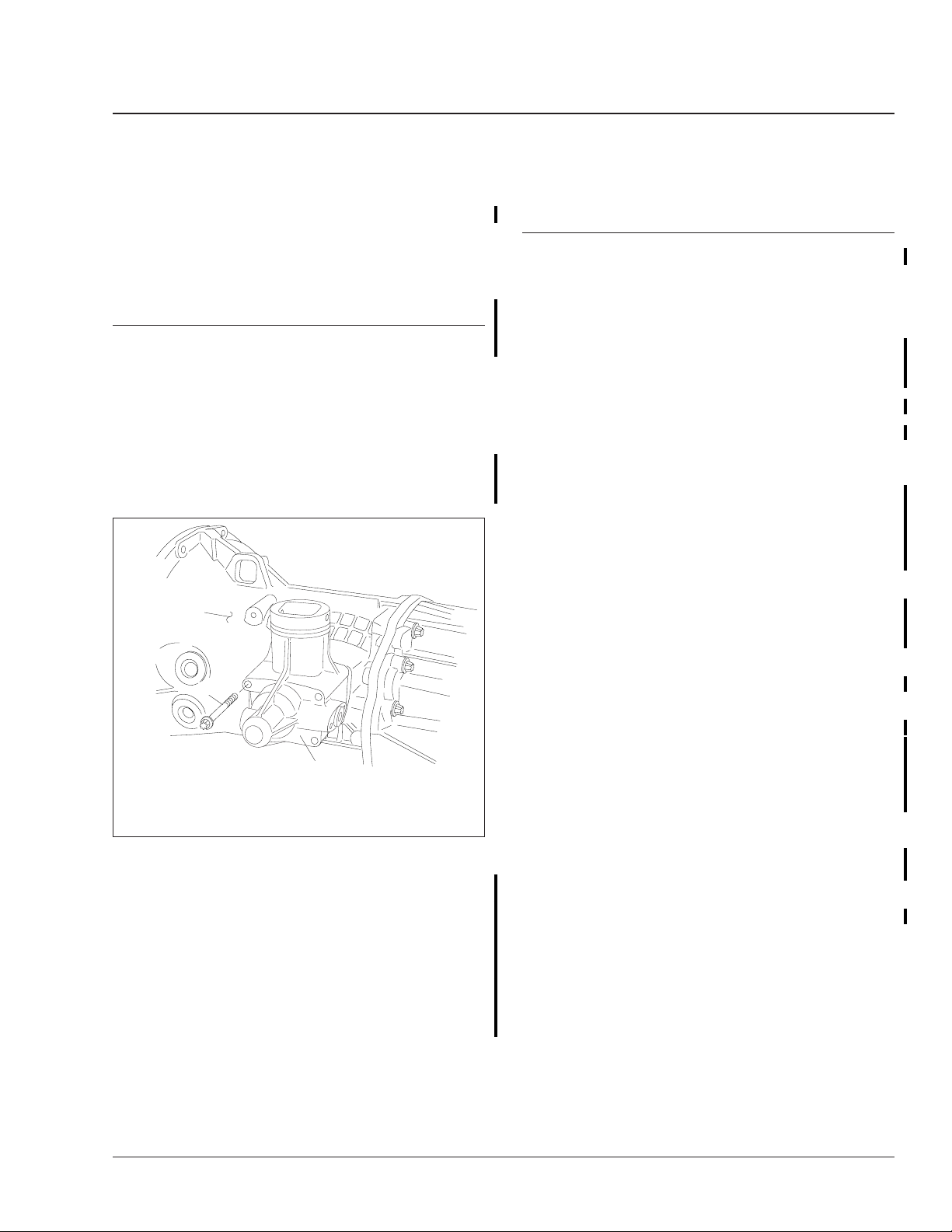
7. Remove the bolts that attach the clutch slave
cylinder to the mounting flange on the gear case.
Move the slave cylinder out of the way. See
Fig. 8.
Business Class M2 Workshop Manual, Supplement 8, September 2005100/2
Mercedes-Benz Manual Transmission
Transmission Removal and Installation
3
2
1
06/05/2001
1. Speedometer Sensor
2. Fuel Line
Fig. 7, Fuel Line Standoff Bracket and Speedometer
3. Standoff Bracket
Sensor
f261009
26.04
05/14/2001
Bend back the nut retainer (arrow).
Fig. 9, Power Take-Off Unit (PTO) Nut Retainers
f261105
2
3
f261107
05/24/2001
1. M8 Bolts
2. Bleed Valve
Fig. 8, Hydraulic Clutch Slave Cylinder
1
3. Slave Cylinder
8. Bend back the nut retainers and remove the
power take-off unit (PTO), if installed. See Fig. 9.
9. If the vehicle is equipped with optional dual fuel
tanks, remove the fuel cross-over line and its
support between the tanks.
10. Disconnect the electrical cable from the speedometer sensor and mark it with a paint pen for
ease of installation. See Fig. 7.
11. Remove the battery cable bracket(s) around the
transmission and move the battery cables out of
the way. See Fig. 10.
3
05/14/2001
1. Battery Cable
2. Battery Cable Clamp
3. Battery Cable Bracket
1
Fig. 10, Battery Cable Routing
2
f261106
12. Remove the exhaust clamp at the exhaust elbow.
For ease of transmission removal and installation, move the exhaust pipe to the side and out
of the way.
13. Support the transmission with a jack. See
Fig. 11.
13.1 Position a transmission jack under the
transmission and raise its support plates
against the base of the transmission.
13.2 Adjust the support plates to cradle the
transmission.
Business Class M2 Workshop Manual, Supplement 8, September 2005 100/3
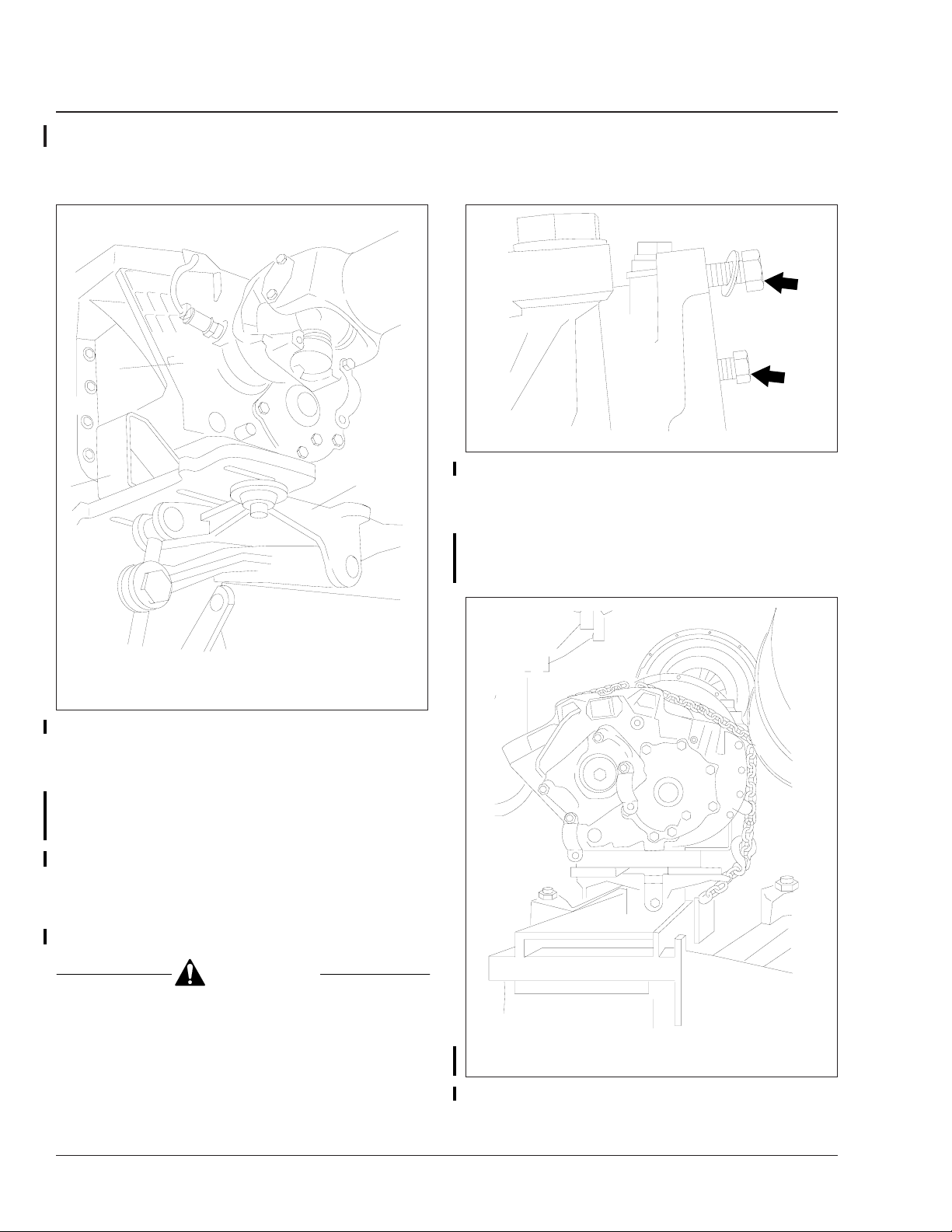
26.04
Mercedes-Benz Manual Transmission
Transmission Removal and Installation
1
2
03/01/99
1. Transmission
2. Support Plate
Fig. 11, Supporting the Transmission
13.3 Using a chain, secure the transmission to
the jack.
14. Remove the 16-mm transmission mounting capscrews that attach the timing case to the bell
housing. See Fig. 12.
14.1 Remove the eleven transmission mounting
capscrews.
14.2 After removing the transmission, insert the
capscrews into the holes in the timing
case, rather than in the bell housing.
3. Jack
3
f261014
01/29/99
Fig. 12, Capscrews Left in the Timing Case
flywheel. Taking these precautions will prevent
damage to the input shaft, flywheel, and clutch.
15. After making sure that the transmission is firmly
secured and well supported, remove the transmission from the vehicle. See Fig. 13.
f261011
CAUTION
Do not allow the rear of the transmission to drop,
and do not allow the transmission to hang unsupported. Keep the flange of the bell housing
parallel (all the way around) to the flange of the
timing case, until the input shaft is clear of the
01/29/99
Make sure that the transmission is firmly secured and
well supported.
Fig. 13, Transmission Ready To Remove
Business Class M2 Workshop Manual, Supplement 8, September 2005100/4
f261013
Mercedes-Benz Manual Transmission
Transmission Removal and Installation
26.04
15.1 Pull the transmission and jack straight
back until the transmission input shaft is
clear of the clutch.
15.2 Turn the left-hand front wheel to allow
room for the transmission to pass. If necessary, lower the jack supporting the
transmission. It might also be necessary
to jack up the truck to get enough clearance to allow the transmission to pass.
IMPORTANT: Watch closely the clearance
between the bell housing and the leaf
spring.
15.3 Pull the transmission out through the
space behind the front wheel.
Installation
IMPORTANT: Before installing the transmission,
make sure that the rear tires are chocked and
that the transmission is securely chained to the
support plates on the transmission jack.
1. Install the transmission. See Fig. 14.
1.1 Align the jack and the transmission behind
the engine.
1.2 Raise the transmission and adjust the
angle of the jack until the bell housing and
the timing case flange are parallel.
1.3 Push the transmission and jack straight
forward.
NOTE: While installing the transmission
mounting capscrews, also install the battery
cable bracket(s), as removed.
1.4 Install the eleven M10 transmission
mounting capscrews. Use a crossover pattern. Do a final tightening of the capscrews to 33 lbf·ft (45 N·m).
1.5 Remove the chain around the transmission and the jack; then remove the jack.
2. Install the exhaust clamp at the exhaust elbow,
as removed.
3. If the vehicle is equipped with the optional dual
fuel tanks, install the fuel cross-over line and its
support between the tanks. Tighten the clamps
3
2
1
11
07/25/2005
NOTE: The transmission is shown from the left-hand
side.
1. Transmission Mounting Capscrews
2. Reverse Gear Switch
3. Shift Lever Mounting Bolt
4. Starter Lock Switch
5. Nameplate
6. Output Yoke Pressure Plate Mounting Capscrew
7. U-Joint End Cap Bolts
8. Speedometer Sensor Lock
9. Transmission Fluid Fill Plug
10. Transmission Fluid Drain Plug
11. PTO Mounting Capscrews
12. Clutch Slave Cylinder Mounting Bolts
40 lbf·ft (54 N·m) and the mounting bolts 95 lbf·ft
(129 N·m).
4. If removed, coat the mating surface of the PTO
cover with Loctite®509 or equivalent sealing
compound. Install the PTO cover on the transmission. Tighten the M10 hardened mounting
capscrews 43 lbf·ft (58 N·m). Lock the nut retainers in place.
5. Connect the driveshaft.
5.1 Slide the front of the driveshaft into the
5.2 Install the U-joint end caps on the output
5.3 Install the midship bearing bracket, as re-
12
Fig. 14, Transmission Fasteners
transmission output yoke.
yoke. Tighten the bolt heads 50 lbf·ft (68
N·m) for 3/8-inch end cap bolts and 110
lbf·ft (149 N·m) for 1/2-inch end cap bolts.
moved. Tighten the nuts 95 lbf·ft (129
N·m).
10
4
5
6
8
9
f261103a
7
Business Class M2 Workshop Manual, Supplement 8, September 2005 100/5
26.04
Mercedes-Benz Manual Transmission
Transmission Removal and Installation
6. Install the fuel line standoff bracket and connect
the fuel lines to the bracket.
7. Connect the electrical connectors. Connect the
electrical cable to the speedometer sensor. Connect the electrical connector(s) on the shift lever.
8. Install the shift lever.
8.1 Fit the shift lever over the cone of the
transmission tower.
8.2 Coat the hardened M10 x 20 shift lever
mounting bolt with Loctite 242 or equivalent thread-locking compound.
8.3 Insert the M10 bolt and a thick washer
into the hole in the shift lever. See Fig. 6.
Use the markings made during removal to
install the shift lever in the correct orientation, so as to avoid cab floor interference.
IMPORTANT: Don’t forget to install the
washer. Without the washer, the shift lever
may loosen. The driver could lose control of
the vehicle.
10/05/94
A. Full B. Low
14. Remove the chocks from the rear tires.
A
Fig. 15, Transmission Fluid Level Checking
B
f260006b
8.4 Tighten the M10 bolt 50 lbf·ft (68 N·m).
8.5 Work the shift lever around to make sure
it shifts comfortably in all gears.
8.6 Install the rubber boot and the metal re-
taining ring. Install the four screws and
tighten against the cab floor 28 lbf·ft (38
N·m). See Fig. 5.
9. Fasten the clutch slave cylinder to the mounting
flange on the gear case and tighten the four M8
slave cylinder mounting bolts 15 lbf·ft (20 N·m).
10. If necessary, bleed the hydraulic clutch system.
See Section 25.02, Subject 140 for detailed instructions.
11. Clean the transmission drain plug and install it in
the gear case, along with a new aluminum gasket. Tighten the drain plug 42 lbf·ft (57 N·m).
®
12. Add Mobiltrans SHC
fluid is level with the lower edge of the fill opening. See Fig. 1 for the location of the fill plug and
Fig. 15 for checking the correct level. About 9.5
quarts (9.0 liters) is needed.
13. Clean the transmission fill plug and install it in
the gear case, along with a new aluminum gasket. Tighten the fill plug 42 lbf·ft (57 N·m).
DC until the transmission
Business Class M2 Workshop Manual, Supplement 8, September 2005100/6
Mercedes-Benz Manual Transmission
Shift Mechanism Removal and Installation
26.04
NOTE: These procedures are for the manual
transmission with shift lever only. For the automated AGS transmission, see Sec-
tion 26.03, Subject 200.
Removal
1. Remove the transmission. For detailed procedures, see Subject 100.
2. Secure the transmission on a wooden pallet, or
other device to keep it from moving.
3. Make sure the transmission is in neutral.
4. Remove the four capscrews that attach the shift
rod housing to the flange on the front gear case.
See Fig. 1.
1
2
03/01/2005
1. Front Gear Case
2. Shift Rod Housing Capscrew
3. Shift Rod Housing
Fig. 1, Shift Mechanism
5. Remove the shift rod from the front gear case.
5.1 From the right-hand side of the transmis-
sion, remove the setscrew that holds the
end of the shift rod. Discard the old setscrew.
5.2 Remove and discard the shift rod cover
from the right-hand side of the gear case.
5.3 Pull the shift rod all the way out of the
gear case.
3
f261178
Installation
NOTE: See the installation procedure in Sec-
tion 26.03, Subject 200 for more information on
the proper alignment of the shift finger in the
shift rod.
1. Make sure that the indent in the shift rod end
(shown by the arrow in Fig. 2) is facing aft for
proper engagement with the setscrew.
2. Install the shift rod in the front gear case.
2.1 Insert the shift rod into the front gear
case.
2.2 Turn the shift rod until the dimple is at the
9 o’clock position.
3. Install the shift rod housing on the front gear
case.
3.1 Push the housing in until the indent in the
rod end is showing in the setscrew hole.
3.2 Coat the threads of a new setscrew with
3.3 Install a new shift rod cover in the shift
3.4 Position the shift rod housing over the
3.5 Install the four capscrews that attach the
4. Install the transmission. For detailed procedures,
see Subject 100.
®
Loctite
compound. Insert the new setscrew and
tighten it 30 lbf·ft (40 N·m). See Fig. 3.
cover housing.
flange in the front gear case. Coat the
mating surfaces with a bead of Loctite 509
or equivalent sealing compound.
shift rod housing to the front gear case.
Coat the threads of the two lower capscrews with Loctite 242 or equivalent
thread-locking compound. Tighten all four
capscrews 18 lbf·ft (25 N·m).
242 or equivalent thread-locking
Business Class M2 Workshop Manual, Supplement 8, September 2005 110/1

Meritor WABCO Pneumatic Antilock Braking System
42.00
Testing
6. Turn the ignition switch off.
7. If the voltage at the ECU is not within the specified range, check the battery voltage and test the
wiring to the ECU and to ground.
8. Connect the X1 connector to the ECU and remove the chocks from the tires.
ABS Pneumatic System Test
To check for air leaks in the ABS pneumatic system,
listen for the sound of escaping air at each valve. To
confirm a slow air leak, apply a soap-and-water solution to air line fittings and watch for bubbles.
ABS/ATC Circuit Pin and Wire Numbers
Pin
Connector
X1
Gray
X2
Black
Pin
Number
1 376C ECU Ignition Supply
2 376C ECU #2 Positive 12 Volt Supply
3 376T Wheel Spin Light and ATC Switch
4 1587+ J1587+
5 376R Retarder Interrupt Signal
6 1922-/1939- J1922–/1939–
7 1922+/1939+ J1922+/1939+
9 1587 J1587–
10 376L ABS Light
11 XGRD ECU Ground
12 XGRD ECU Ground
1 — Not used
2 378LFI Left Front Modulator Valve, In
3 378RF0 Right Front Modulator Valve, Out
4 378RFI Right Front Modulator Valve, In
5 377RF+ Right Front Sensor, High
6 377RF– Right Front Sensor, Low
7 377LF– Left Front Sensor, Low
8 377LF+ Left Front Sensor, High
9 378RF– Right Front Modulator Valve, Ground
10 378LF0 Left Front Modulator Valve, Out
11 378LF– Left Front Modulator Valve, Ground
12 — Not used
Wire
Number
(ABS)
Wheel Speed Sensor Tests
Wheel Speed Sensor and Circuit
Resistance
To check the resistance in a wheel speed sensor circuit, perform the following test:
1. Park the vehicle on a level surface, set the parking brake, and shut down the engine. Chock the
rear tires.
2. Disconnect the sensor cable connector from the
ABS ECU. See Table 1.
Circuit Description
Business Class M2 Workshop Manual, Supplement 0, January 2002170/2

Meritor WABCO Pneumatic Antilock Braking System
(ABS)
Pin
Connector
X3
Green
ABS/ATC Circuit Pin and Wire Numbers
Pin
Number
1 377LR+ Left Rear Sensor, High
2 377LR– Left Rear Sensor, Low
3 377RR+ Right Rear Sensor, High
4 377RR– Right Rear Sensor, Low
5 378T+ ATC Valve, High
6 378T– ATC Valve, Low
7 378RR0 Right Rear Modulator Valve, Out
8 378RR– Right Rear Modulator Valve, Ground
9 378RRI Right Rear Modulator Valve, In
10 378LR0 Left Rear Modulator Valve, Out
11 378LR– Left Rear Modulator Valve, Ground
12 378LRI Left Rear Modulator Valve, In
Table 1, ABS/ATC Circuit Pin and Wire Numbers
Wire
Number
Circuit Description
42.00
Testing
3. Connect ohmmeter probes to the sensor connector terminals and read the resistance.
• If the resistance is 900 to 2000 ohms, the
cable and the sensor circuit are good. Proceed to the "Wheel Speed Sensor Voltage"
test.
• If the resistance is less than 900 ohms or
greater than 2000 ohms, perform the next
test, "Wheel Speed Sensor Resistance."
Wheel Speed Sensor Resistance
To check the resistance in a wheel speed sensor,
perform the following test:
1. Park the vehicle on a level surface, set the parking brake, and shut down the engine. Chock the
rear tires.
2. Disconnect the wheel sensor cable from the
chassis harness.
3. Connect ohmmeter probes to the pins on the
sensor and read the resistance.
• If the resistance reading is 900 to 2000
ohms but the resistance noted in the previous test, "Wheel Speed Sensor and Circuit
Resistance" was not, repair or replace the
chassis harness wiring.
• If the resistance is less than 900 ohms or
greater than 2000 ohms, clean the terminals and check the resistance again.
• If the resistance reading is still not correct,
replace the sensor. See Subject 110 for
instructions.
4. Install the connectors and remove the chocks
from the tires.
Wheel Speed Sensor Voltage
NOTE: PC diagnostics can be used for this test
to compare speed signal output of all sensors. A
problem will be indicated by low or erratic output.
To check the voltage output of a wheel speed sensor:
1. Park the vehicle on a level surface, set the parking brake, and shut down the engine.
2. Chock the tires of the axle not being tested.
Raise the vehicle and put jack stands under the
axle so the wheels can rotate.
3. Disconnect the applicable connector from the
ABS ECU for the sensor being tested. See
Table 1.
Business Class M2 Workshop Manual, Supplement 0, January 2002 170/3

Meritor WABCO Pneumatic Antilock Braking System
42.00
Testing
4. Set a digital multimeter to the AC voltmeter
mode. Connect the probes to the cable connector terminals for the sensor being tested.
5. Rotate the wheel by hand at a speed of 30 rpm
(one-half revolution per second) and read the
voltage output. The wheel speed sensor must
generate a minimum of 0.2 volt AC.
• If the voltage is at least 0.2 volt AC, skip to
the next step.
• If the voltage reading is less than 0.2 volt
AC, push the sensor in its holder until the
sensor touches the tooth wheel. See Sub-
ject 120 for instructions. Repeat the volt-
age test.
• If the sensor output is still less than 0.2
volt AC, replace the sensor.
6. Install the connector on the ECU. Remove the
jack stands, lower the vehicle, and remove the
chocks from the tires.
Modulator Valve Tests
(ABS)
A
3
2
04/09/97
NOTE: During the self-test, the valves cycle one by one
in order (1–2–3–4), then in pairs diagonally (1/2 and
3/4). A 4-channel valve cycle is shown.
A. Cab B. Curbside
1. Right Front Modulator Valve
2. Left Rear Modulator Valve
3. Left Front Modulator Valve
4. Right Rear Modulator Valve
1
B
4
f421562
Modulator Valve Function Check
NOTE: Valves can be tested using the Meritor
WABCO PC Diagnostics software or the following procedure.
Modulator valves control the air pressure to each affected brake during an ABS function. To make sure
the modulator valves are working, listen to them
cycle during the ABS self-test.
1. Park the vehicle on a level surface, set the parking brake, and shut down the engine. Chock the
rear tires.
2. Turn the ignition switch on.
3. When the ABS warning light comes on, listen for
the modulator valves to cycle one by one, then
together diagonally. See Fig. 2.
• 4-Channel valve cycle: 1, 2, 3, 4; then 1
and 2 together followed by 3 and 4.
• 6-Channel valve cycle: 1, 2, 3, 4, 5, 6;
then 1, 2, and 3 together followed by 4, 5,
and 6.
4. If the valves do not all cycle correctly, turn the
ignition off and check the connectors for tightness. Repeat the self-test.
Fig. 2, Modulator Valve Self-Test Sequence
5. If the valves still do not cycle correctly, start the
engine and check the air line connections to the
valves for leaks. Shut down the engine and
tighten the air line fittings. Repeat the self-test.
6. If the valves still do not cycle correctly, check for
fault codes. Perform the next test, "Modulator
Valve and Cable Resistance."
Modulator Valve and Cable
Resistance
To check the resistance in a modulator valve and
cable circuit, perform the following test:
1. Park the vehicle on a level surface, set the parking brake, and shut down the engine. Chock the
rear tires.
2. Disconnect the modulator valve connector from
the ABS ECU. See Table 1.
3. Connect ohmmeter probes to the cable connector pins for the modulator valve "In" solenoid and
"Ground." Read the resistance. Then, move the
probes to the "Out" and "Ground" pins and read
the resistance.
Business Class M2 Workshop Manual, Supplement 0, January 2002170/4

Meritor WABCO Pneumatic Antilock Braking System
(ABS)
4. The resistance in each solenoid coil and cable
circuit must be 4 to 8 ohms.
• If the resistance in each solenoid circuit is
4 to 8 ohms, the cable and modulator
valve are good. Install the connector on
the ECU and remove the chocks from the
tires.
• If the resistance in either solenoid circuit is
less than 4 ohms or greater than 8 ohms,
go to the next test, "Modulator Valve Resistance."
Modulator Valve Resistance
To check the resistance in the solenoid coils in an
ABS modulator valve, perform the following test:
1. Park the vehicle on a level surface, set the parking brake, and shut down the engine. Chock the
rear tires.
2. Disconnect the cable connector from the modulator valve being tested. See Table 1.
3. Connect ohmmeter probes to the modulator
valve "In" solenoid and "Ground" terminals and
read the resistance. Then, move the probes to
the "Out" and "Ground" terminals and read the
resistance. See Fig. 3 for the modulator terminal
locations.
A
B
1
2
3
08/30/99
A. Delivery Port B. Supply Port
1. Ground (Common)
2. Exhaust Solenoid (Out)
3. Supply Solenoid (In)
Fig. 3, Modulator Valve Terminals
4. The resistance in each solenoid coil must be 4 to
8 ohms.
f430143
42.00
Testing
• If the resistance in each solenoid coil is 4
to 8 ohms but the resistance noted in the
previous test, "Modulator Valve and Cable
Resistance" was not, repair or replace the
chassis harness.
• If the resistance is less than 4 ohms or
greater than 8 ohms, clean the terminals
on the modulator valve and check the resistance again.
• If the resistance is still not correct, replace
the valve. See Subject 130 for instructions.
5. Install the cable connectors and remove the
chocks from the tires.
ATC Valve Tests
ATC Valve and Cable Resistance
To check the resistance in the ATC valve and cable
circuit, perform the following test:
1. Park the vehicle on a level surface, set the parking brake, and shut down the engine. Chock the
rear tires.
2. Disconnect the ATC valve connector (X3) from
the ABS ECU. See Table 1.
3. Connect ohmmeter probes to the cable connector pins 5 and 6 for the ATC valve and read the
resistance.
4. The resistance in the ATC solenoid coil and
cable circuit must be 6.4 to 12 ohms.
• If the resistance is 6.4 to 12 ohms, the
ATC valve and cable are good. Install the
cable connector on the ECU and remove
the chocks from the tires.
• If the resistance is less than 6.4 ohms or
greater than 12 ohms go to the next test,
"ATC Valve Resistance."
ATC Valve Resistance
To check the resistance in the solenoid coil in the
ATC valve, perform the following test:
1. Park the vehicle on a level surface, set the parking brake, and shut down the engine. Chock the
rear tires.
Business Class M2 Workshop Manual, Supplement 0, January 2002 170/5

Meritor WABCO Pneumatic Antilock Braking System
42.00
Testing
2. Disconnect the cable connector from the ATC
valve. See Table 1.
3. Connect ohmmeter probes to the ATC valve terminals and read the resistance. See Fig. 4.
3
2
08/30/99
1. ATC Valve
2. Rear Modulator Valve Assembly
3. ATC Solenoid Terminals
1
f430144
(ABS)
Fig. 4, ATC Valve Terminals
4. The resistance of the ATC solenoid coil and its
wiring must be 6.4 to 12 ohms.
• If the resistance is 6.4 to 12 ohms but the
resistance noted in the previous test, "ATC
Valve and Cable Resistance" was not, repair or replace the electrical cable.
• If the resistance is less than 6.4 ohms or
greater than 12 ohms, clean the terminals
on the ATC valve and check the resistance
again.
• If the resistance is still not correct, replace
the valve. See Subject 140 for instructions.
5. Install the connectors and remove the chocks
from the tires.
Business Class M2 Workshop Manual, Supplement 0, January 2002170/6

Meritor WABCO Pneumatic Antilock Braking System
(ABS)
Troubleshooting Tables
Using the following tables, troubleshoot the ABS system by MID-SID.
J1587 Fault Code Cross-Reference
MID-SID Description
Wheel Sensor
136-001
136-002
136-003
136-004
136-007
136-008
136-009
136-010
Left Front
Right Front
Left Rear
Right Rear
Modulator Valve
Left Front
Right Front
Left Rear
Right Rear
Troubleshooting
Table
Table 2
Table 3
Table 4
Table 5
Table 6
Table 7
Table 8
Table 9
42.00
ABS System Troubleshooting
J1587 Fault Code Cross-Reference
MID-SID Description
136-014
136-015
136-018 ATC Valve (if equipped) Table 12
136-019 Auxiliary Output Table 13
136-023 ABS Warning Lamp See Subject 310
136-231 J1939 Datalink Table 14
136-251 Voltage Table 15
136-253 Configuration Errors Table 16
136-254 Miscellaneous Faults Table 17
Table 1, J1587 Fault Code Cross Reference
Ground Faults Table 10
Troubleshooting
Table
Table 11
Left Front Wheel Sensor Troubleshooting (SID 001)
MID SID FMI Problem Test Test Result Action
136 001 01 Incorrect sensor
air gap
136 001 02 Incorrect tire size Check for correct tire size and
136 001 03 Sensor shorted to
power
1. Adjust the sensor.
Check the AC voltage
across pins 7 and 8 of the
black X2 ECU connector
while rotating the LF wheel
30 rpm.
2. Measure the voltage
across pins 7 of the X2
(black) connector and a
good chassis ground.
Repeat the test between
pin 8 and ground.
Voltage is 0.2 Vac
or greater
Voltage is less
than 0.2 Vac
Measurable
voltage at either
pin
No voltage at
either pin
Sensor adjustment solved the
problem.
Check for excessive wheel
bearing end play and hub runout.
Repair as needed.
mixed tire sizes. Check for correct
number of teeth on tone wheel.
Correct as needed.
Repair short to power in circuit(s)
377LF+ and 377LF– in chassis
harness and sensor cable.
If problem is in the sensor
harness, replace the sensor.
Repeat the test and check for
intermittent short to power in
circuits 377LF+ and 377LF–.
Suspect ECU is at fault if the
problem persists.
Business Class M2 Workshop Manual, Supplement 2, June 2002 300/1

Meritor WABCO Pneumatic Antilock Braking System
42.00
ABS System Troubleshooting
Left Front Wheel Sensor Troubleshooting (SID 001)
MID SID FMI Problem Test Test Result Action
136 001 04 Short to ground 3. Measure the resistance
between pin 7 of the X2
(black) connector and a
good chassis ground.
Repeat the test between
pin 8 and ground.
136 001 05 Open circuit 4. Measure the resistance
between pins 7u and 8 of
the X2 (black) connector.
136 001 05 Open circuit 5. Disconnect the sensor
connector from the chassis
harness. Measure the
resistance between the
pins on the sensor
connector.
136 001 06 Short circuit Perform tests 4 and 5.
136 001 07 Damaged tone
ring
136 001 08 Excessive wheel
slip
136 001 09 Wire mismatch 6. Check for mixed sensor
connection. Using Meritor
PC Diagnostics, spin each
wheel individually. Check
that output is from the
correct sensor.
Resistance
between either pin
and ground is less
than 100,000 ohms
Resistance
between either pin
and ground is
greater than
100,000 ohms
Resistance is 900–
2000 ohms
Resistance is
greater than 2000
ohms OR less than
900 ohm.
Resistance is 900–
2000 ohms
Resistance is
greater than 2000
ohms OR less than
900 ohms
Repair the short to ground in
circuit(s) 377LF+ and 377LF– in
chassis harness or sensor cable.
If problem is in sensor harness,
replace the sensor.
Repeat the test for intermittent
short to ground in circuits 377LF+
and 377LF–.
Suspect ECU is at fault if the
problem persists.
Repeat the test and check for
intermittent open or short in
circuits 377LF+ and 377LF–.
Suspect ECU at fault if the
problem persists.
Perform test 5.
Repair open or short in circuit(s)
377LF+ and 377LF– in chassis
harness.
Replace the sensor.
Inspect tone ring for damage and
missing teeth. Make sure correct
tooth wheel is installed (100-tooth
is normal application). Repair as
needed.
Check sensor adjustment. This
fault usually occurs when there is
excessive tire spin for more than
16 seconds.
Correct wiring connections, as
needed.
(ABS)
Business Class M2 Workshop Manual, Supplement 2, June 2002300/2

Meritor WABCO Pneumatic Antilock Braking System
(ABS)
42.00
ABS System Troubleshooting
Left Front Wheel Sensor Troubleshooting (SID 001)
MID SID FMI Problem Test Test Result Action
136 001 10 Intermittent signal 7. Adjust the sensor. Using
136 001 11 Erratic signal Perform test 7.
136 001 12 Frequency too
high
Table 2, Left Front Wheel Sensor Troubleshooting (SID 001)
MID SID FMI Problem Test Test Result Action
136 002 01 Incorrect sensor
air gap
136 002 02 Incorrect tire size Check for correct tire size and
136 002 03 Sensor shorted to
power
the wheel sensor output
screen in Meritor PC
Diagnostics, spin the
wheel or drive the vehicle
and check for intermittent
or erratic signal.
8. Check sensor wiring
and connectors for
intermittent contact.
Right Front Wheel Sensor Troubleshooting (SID 002)
1. Adjust the sensor.
Check the AC voltage
across pins 5 and 6 of the
black X2 ECU connector
while rotating the RF
wheel 30 rpm.
2. Measure the voltage
across pin 5 of the X2
(black) connector and a
good chassis ground.
Repeat the test between
pin 8 and ground.
Signal output OK Adjustment solved the problem.
Signal output
incorrect
Wiring OK Suspect ECU at fault if problem
Wiring incorrect Repair wheel sensor circuit, as
Voltage is 0.2 Vac
or greater
Voltage is less
than 0.2 Vac
Measurable
voltage at either
pin
No voltage at
either pin
Make sure brake chatter is not
causing the problem.
Check for intermittent wheel
sensor circuit connections. Cause
could be due to brake chatter.
Repair as needed.
persists.
needed.
Sensor adjustment solved the
problem.
Check for excessive wheel
bearing end play and hub runout.
Repair as needed.
mixed tire sizes. Check for correct
number of teeth on tone wheel.
Correct as needed.
Repair short to power in circuit(s)
377RF+ and 377RF– in chassis
harness and sensor cable.
If problem is in the sensor
harness, replace the sensor.
Repeat the test and check for
intermittent short to power in
circuits 377RF+ and 377RF–.
Suspect ECU is at fault if the
problem persists.
Business Class M2 Workshop Manual, Supplement 2, June 2002 300/3

Meritor WABCO Pneumatic Antilock Braking System
42.00
ABS System Troubleshooting
Right Front Wheel Sensor Troubleshooting (SID 002)
MID SID FMI Problem Test Test Result Action
136 002 04 Short to ground 3. Measure the resistance
between pin 5 of the X2
(black) connector and a
good chassis ground.
Repeat the test between
pin 6 and ground.
136 002 05 Open circuit 4. Measure the resistance
between pins 5 and 6 of
the X2 (black) connector.
5. Disconnect the sensor
connector from the chassis
harness. Measure the
resistance between the
pins on the sensor
connector.
136 002 06 Short circuit Perform tests 4 and 5.
136 002 07 Damaged tone
ring
136 002 08 Excessive wheel
slip
136 002 09 Wire mismatch 6. Check for mixed sensor
connection. Using Meritor
PC Diagnostics, spin each
wheel individually. Check
that output is from the
correct sensor.
Resistance
between either pin
and ground is less
than 100,000 ohms
Resistance
between either pin
and ground is
greater than
100,000 ohms
Resistance is 900–
2000 ohms
Resistance is
greater than 2000
ohms OR less than
900 ohm.
Resistance is 900–
2000 ohms
Resistance is
greater than 2000
ohms OR less than
900 ohms
Repair the short to ground in
circuit(s) 377RF+ and 377RF– in
chassis harness or sensor cable.
If problem is in sensor harness,
replace the sensor.
Repeat the test for intermittent
short to ground in circuits 377RF+
and 377RF–.
Suspect ECU is at fault if the
problem persists.
Repeat the test and check for
intermittent open or short in
circuits 377RF+ and 377RF–.
Suspect ECU at fault if the
problem persists.
Perform test 5.
Repair open or short in circuit(s)
377RF+ and 377RF– in chassis
harness.
Replace the sensor.
Inspect tone ring for damage and
missing teeth. Make sure correct
tooth wheel is installed (100-tooth
is normal application). Repair as
needed.
Check sensor adjustment. This
fault usually occurs when there is
excessive tire spin for more than
16 seconds.
Correct wiring connections, as
needed.
(ABS)
Business Class M2 Workshop Manual, Supplement 2, June 2002300/4

Meritor WABCO Pneumatic Antilock Braking System
(ABS)
42.00
ABS System Troubleshooting
Right Front Wheel Sensor Troubleshooting (SID 002)
MID SID FMI Problem Test Test Result Action
136 002 10 Intermittent signal 7. Adjust the sensor. Using
136 002 11 Erratic signal Perform test 7.
136 002 12 Frequency too
high
Table 3, Right Front Wheel Sensor Troubleshooting (SID 002)
MID SID FMI Problem Test Test Result Action
136 003 01 Incorrect sensor
air gap
136 003 02 Incorrect tire size Check for correct tire size and
136 003 03 Sensor shorted to
power
the wheel sensor output
screen in Meritor PC
Diagnostics, spin the
wheel or drive the vehicle
and check for intermittent
or erratic signal.
8. Check sensor wiring
and connectors for
intermittent contact.
Left Rear Wheel Sensor Troubleshooting (SID 003)
1. Adjust the sensor.
Check the AC voltage
across pins 1 and 2 of the
black X2 ECU connector
while rotating the LR
wheel 30 rpm.
2. Measure the voltage
across pin 1 of the X3
(green) connector and a
good chassis ground.
Repeat the test between
pin 2 and ground.
Signal output OK Adjustment solved the problem.
Signal output
incorrect
Wiring OK Suspect ECU at fault if problem
Wiring incorrect Repair wheel sensor circuit, as
Voltage is 0.2 Vac
or greater
Voltage is less
than 0.2 Vac
Measurable
voltage at either
pin
No voltage at
either pin
Make sure brake chatter is not
causing the problem.
Check for intermittent wheel
sensor circuit connections. Cause
could be due to brake chatter.
Repair as needed.
persists.
needed.
Sensor adjustment solved the
problem.
Check for excessive wheel
bearing end play and hub runout.
Repair as needed.
mixed tire sizes. Check for correct
number of teeth on tone wheel.
Correct as needed.
Repair short to power in circuit(s)
377LR+ and 377LR– in chassis
harness and sensor cable.
If problem is in the sensor
harness, replace the sensor.
Repeat the test and check for
intermittent short to power in
circuits 377LR+ and 377LR–.
Suspect ECU is at fault if the
problem persists.
Business Class M2 Workshop Manual, Supplement 2, June 2002 300/5

Meritor WABCO Pneumatic Antilock Braking System
42.00
ABS System Troubleshooting
Left Rear Wheel Sensor Troubleshooting (SID 003)
MID SID FMI Problem Test Test Result Action
136 003 04 Short to ground 3. Measure the resistance
between pin 1 of the X3
(green) connector and a
good chassis ground.
Repeat the test between
pin 2 and ground.
136 003 05 Open circuit 4. Measure the resistance
between pins 1 and 2 of
the X3 (green) connector.
5. Disconnect the sensor
connector from the chassis
harness. Measure the
resistance between the
pins on the sensor
connector.
136 003 06 Short circuit Perform tests 4 and 5.
136 003 07 Damaged tone
ring
136 003 08 Excessive wheel
slip
136 003 09 Wire mismatch 6. Check for mixed sensor
connection. Using Meritor
PC Diagnostics, spin each
wheel individually. Check
that output is from the
correct sensor.
Resistance
between either pin
and ground is less
than 100,000 ohms
Resistance
between either pin
and ground is
greater than
100,000 ohms
Resistance is 900–
2000 ohms
Resistance is
greater than 2000
ohms OR less than
900 ohm.
Resistance is 900–
2000 ohms
Resistance is
greater than 2000
ohms OR less than
900 ohms
Repair the short to ground in
circuit(s) 377LR+ and 377LR– in
chassis harness or sensor cable.
If problem is in sensor harness,
replace the sensor.
Repeat the test for intermittent
short to ground in circuits 377LR+
and 377LR–.
Suspect ECU is at fault if the
problem persists.
Repeat the test and check for
intermittent open or short in
circuits 377LR+ and 377LR–.
Suspect ECU at fault if the
problem persists.
Perform test 5.
Repair open or short in circuit(s)
377LR+ and 377LR– in chassis
harness.
Replace the sensor.
Inspect tone ring for damage and
missing teeth. Make sure correct
tooth wheel is installed (100-tooth
is normal application). Repair as
needed.
Check sensor adjustment. This
fault usually occurs when there is
excessive tire spin for more than
16 seconds.
Correct wiring connections, as
needed.
(ABS)
Business Class M2 Workshop Manual, Supplement 2, June 2002300/6

Meritor WABCO Pneumatic Antilock Braking System
(ABS)
42.00
ABS System Troubleshooting
Left Rear Wheel Sensor Troubleshooting (SID 003)
MID SID FMI Problem Test Test Result Action
136 003 10 Intermittent signal 7. Adjust the sensor. Using
136 003 11 Erratic signal Perform test 7.
136 003 12 Frequency too
high
Table 4, Left Rear Wheel Sensor Troubleshooting (SID 003)
MID SID FMI Problem Test Test Result Action
136 004 01 Incorrect sensor
air gap
136 004 02 Incorrect tire size Check for correct tire size and
136 004 03 Sensor shorted to
power
the wheel sensor output
screen in Meritor PC
Diagnostics, spin the
wheel or drive the vehicle
and check for intermittent
or erratic signal.
8. Check sensor wiring
and connectors for
intermittent contact.
Right Rear Wheel Sensor Troubleshooting (SID 004)
1. Adjust the sensor.
Check the AC voltage
across pins 3 and 4 of the
black X2 ECU connector
while rotating the RR
wheel 30 rpm.
2. Measure the voltage
across pin 3 of the X3
(green) connector and a
good chassis ground.
Repeat the test between
pin 4 and ground.
Signal output OK Adjustment solved the problem.
Signal output
incorrect
Wiring OK Suspect ECU at fault if problem
Wiring incorrect Repair wheel sensor circuit, as
Voltage is 0.2 VAC
or greater
Voltage is less
than 0.2 VAC
Measurable
voltage at either
pin
No voltage at
either pin
Make sure brake chatter is not
causing the problem.
Check for intermittent wheel
sensor circuit connections. Cause
could be due to brake chatter.
Repair as needed.
persists.
needed.
Sensor adjustment solved the
problem.
Check for excessive wheel
bearing end play and hub runout.
Repair as needed.
mixed tire sizes. Check for correct
number of teeth on tone wheel.
Correct as needed.
Repair short to power in circuit(s)
377RR+ and 377RR– in chassis
harness and sensor cable.
If problem is in the sensor
harness, replace the sensor.
Repeat the test and check for
intermittent short to power in
circuits 377RR+ and 377RR–.
Suspect ECU is at fault if the
problem persists.
Business Class M2 Workshop Manual, Supplement 2, June 2002 300/7

Meritor WABCO Pneumatic Antilock Braking System
42.00
ABS System Troubleshooting
Right Rear Wheel Sensor Troubleshooting (SID 004)
MID SID FMI Problem Test Test Result Action
136 004 04 Short to ground 3. Measure the resistance
between pin 3 of the X3
(green) connector and a
good chassis ground.
Repeat the test between
pin 4 and ground.
136 004 05 Open circuit 4. Measure the resistance
between pins 3 and 4 of
the X3 (green) connector.
5. Disconnect the sensor
connector from the chassis
harness. Measure the
resistance between the
pins on the sensor
connector.
136 004 06 Short circuit Perform tests 4 and 5.
136 004 07 Damaged tone
ring
136 004 08 Excessive wheel
slip
136 004 09 Wire mismatch 6. Check for mixed sensor
connection. Using Meritor
PC Diagnostics, spin each
wheel individually. Check
that output is from the
correct sensor.
Resistance
between either pin
and ground is less
than 100,000 ohms
Resistance
between either pin
and ground is
greater than
100,000 ohms
Resistance is 900–
2000 ohms
Resistance is
greater than 2000
ohms OR less than
900 ohm.
Resistance is 900–
2000 ohms
Resistance is
greater than 2000
ohms OR less than
900 ohms
Repair the short to ground in
circuit(s) 377RR+ and 377RR– in
chassis harness or sensor cable.
If problem is in sensor harness,
replace the sensor.
Repeat the test for intermittent
short to ground in circuits
377RR+ and 377RR–.
Suspect ECU is at fault if the
problem persists.
Repeat the test and check for
intermittent open or short in
circuits 377RR+ and 377RR–.
Suspect ECU at fault if the
problem persists.
Perform test 5.
Repair open or short in circuit(s)
377RR+ and 377RR– in chassis
harness.
Replace the sensor.
Inspect tone ring for damage and
missing teeth. Make sure correct
tooth wheel is installed (100-tooth
is normal application). Repair as
needed.
Check sensor adjustment. This
fault usually occurs when there is
excessive tire spin for more than
16 seconds.
Correct wiring connections, as
needed.
(ABS)
Business Class M2 Workshop Manual, Supplement 2, June 2002300/8

Meritor WABCO Pneumatic Antilock Braking System
(ABS)
ABS System Troubleshooting
Right Rear Wheel Sensor Troubleshooting (SID 004)
MID SID FMI Problem Test Test Result Action
136 004 10 Intermittent signal 7. Adjust the sensor. Using
136 004 11 Erratic signal Perform test 7.
136 004 12 Frequency too
high
Table 5, Right Rear Wheel Sensor Troubleshooting (SID 004)
MID SID FMI Problem Test Test Result Action
136 007 03 Short to power
Inlet or outlet
circuit shorted to
battery supply or
another modulator
valve wire.
136 007 05 Open circuit
Inlet or outlet
circuit open.
136 007 06 Short to ground
Inlet or outlet
circuit shorted to
ground.
Table 6, Left Front Modulator Valve Troubleshooting (SID 007)
the wheel sensor output
screen in Meritor PC
Diagnostics, spin the
wheel or drive the vehicle
and check for intermittent
or erratic signal.
8. Check sensor wiring
and connectors for
intermittent contact.
Left Front Modulator Valve Troubleshooting (SID 007)
1. Measure the voltage
between pins 2, 10, and
11 of the X2 (black)
connector and a good
chassis ground.
2. Check the modulator
valve inlet and outlet
circuit resistance.
Disconnect the connector
from the valve and
perform the modulator
valve resistance test.
3. Check the modulator
valve inlet and outlet
circuit resistance.
Disconnect the connector
from the valve and
perform the modulator
valve test.
Signal output OK Adjustment solved the problem.
Signal output
incorrect
Wiring OK Suspect ECU at fault if problem
Wiring incorrect Repair wheel sensor circuit, as
No voltage at
either pin
Measurable
voltage at either
pin
Resistance in both
circuits is within 4
to 8 ohms.
Resistance in both
circuits is not within
4 to 8 ohms.
Resistance in both
circuits is within 4
to 8 ohms.
Resistance in both
circuits is not within
4 to 8 ohms.
Make sure brake chatter is not
causing the problem.
Check for intermittent wheel
sensor circuit connections. Cause
could be due to brake chatter.
Repair as needed.
persists.
needed.
Repeat test. Check circuits
378LFI, 378LFO, and 378LF– for
intermittent short to power. Check
above circuits for shorts to other
modulator valve wires. Repair as
necessary.
If problem persists, the suspect
ECU is at fault.
Repair short to power in circuit
378LFI, 378LFO, or 378LF–.
Check harness wiring circuits
378LFI, 378LFO, or 378LF–.
Replace the modulator valve.
Check harness wiring circuits
378LFI, 378LFO, or 378LF– for
short to ground. Repair as
necessary.
Replace modulator valve.
42.00
Business Class M2 Workshop Manual, Supplement 2, June 2002 300/9

Meritor WABCO Pneumatic Antilock Braking System
42.00
ABS System Troubleshooting
Right Front Modulator Valve Troubleshooting (SID 008)
MID SID FMI Problem Test Test Result Action
136 008 03 Short to power
Inlet or outlet
circuit shorted to
battery supply or
another modulator
valve wire.
136 008 05 Open circuit
Inlet or outlet
circuit open.
136 008 06 Short to ground
Inlet or outlet
circuit shorted to
ground.
Table 7, Right Front Modulator Valve Troubleshooting (SID 008)
1. Measure the voltage
between pins 3, 4, and 9
of the X2 (black)
connector and a good
chassis ground.
2. Check the modulator
valve inlet and outlet
circuit resistance.
Disconnect the connector
from the valve and
perform the modulator
valve resistance test.
3. Check the modulator
valve inlet and outlet
circuit resistance.
Disconnect the connector
from the valve and
perform the modulator
valve test.
No voltage at
either pin
Measurable
voltage at either
pin
Resistance in both
circuits is within 4
to 8 ohms.
Resistance in both
circuits is not within
4 to 8 ohms.
Resistance in both
circuits is within 4
to 8 ohms.
Resistance in both
circuits is not within
4 to 8 ohms.
Repeat test. Check circuits
378RFO, 378RFI, and 378RF– for
intermittent short to power. Check
above circuits for shorts to other
modulator valve wires. Repair as
necessary.
If problem persists, the suspect
ECU is at fault.
Repair short to power in circuit
378RFO, 378RFI, or 378RF–.
Check harness wiring circuits
378RFO, 378RFI, or 378RF–.
Replace the modulator valve.
Check harness wiring circuits
378RFO, 378RFI, or 378RF– for
short to ground. Repair as
necessary.
Replace modulator valve.
(ABS)
Left Rear Modulator Valve Troubleshooting (SID 009)
MID SID FMI Problem Test Test Result Action
136 009 03 Short to power
Inlet or outlet
circuit shorted to
battery supply or
another modulator
valve wire.
136 009 05 Open circuit
Inlet or outlet
circuit open.
1. Measure the voltage
between pins 10, 11, and
12 of the X3 (green)
connector and a good
chassis ground.
2. Check the modulator
valve inlet and outlet
circuit resistance.
Disconnect the connector
from the valve and
perform the modulator
valve resistance test.
No voltage at
either pin
Measurable
voltage at either
pin
Resistance in both
circuits is within 4
to 8 ohms.
Resistance in both
circuits is not within
4 to 8 ohms.
Business Class M2 Workshop Manual, Supplement 2, June 2002300/10
Repeat test. Check circuits
378LRI, 378LRO, and 378LR– for
intermittent short to power. Check
above circuits for shorts to other
modulator valve wires. Repair as
necessary.
If problem persists, the suspect
ECU is at fault.
Repair short to power in circuit
378LRI, 378LRO, or 378LR–.
Check harness wiring circuits
378LRI, 378LRO, and 378LR–.
Replace the modulator valve.

Meritor WABCO Pneumatic Antilock Braking System
(ABS)
ABS System Troubleshooting
Left Rear Modulator Valve Troubleshooting (SID 009)
MID SID FMI Problem Test Test Result Action
136 009 06 Short to ground
Inlet or outlet
circuit shorted to
ground.
Table 8, Left Rear Modulator Valve Troubleshooting (SID 009)
MID SID FMI Problem Test Test Result Action
136 010 03 Short to power
Inlet or outlet
circuit shorted to
battery supply or
another modulator
valve wire.
136 010 05 Open circuit
Inlet or outlet
circuit open.
136 010 06 Short to ground
Inlet or outlet
circuit shorted to
ground.
Table 9, Right Rear Modulator Valve Troubleshooting (SID 010)
3. Check the modulator
valve inlet and outlet
circuit resistance.
Disconnect the connector
from the valve and
perform the modulator
valve test.
Right Rear Modulator Valve Troubleshooting (SID 010)
1. Measure the voltage
between pins 7, 8, and 9
of the X3 (green)
connector and a good
chassis ground.
2. Check the modulator
valve inlet and outlet
circuit resistance.
Disconnect the connector
from the valve and
perform the modulator
valve test.
3. Check the modulator
valve inlet and outlet
circuit resistance.
Disconnect the connector
from the valve and
perform the modulator
valve test.
Resistance in both
circuits is within 4
to 8 ohms.
Resistance in both
circuits is not within
4 to 8 ohms.
No voltage at
either pin
Measurable
voltage at either
pin
Resistance in both
circuits is within 4
to 8 ohms.
Resistance in both
circuits is not within
4 to 8 ohms.
Resistance in both
circuits is within 4
to 8 ohms.
Resistance in both
circuits is not within
4 to 8 ohms.
Check harness wiring circuits
378LRI, 378LRO, and 378LR– for
short to ground. Repair as
necessary.
Replace modulator valve.
Repeat test. Check circuits
378RRO, 378RR–, and 378RRI
for intermittent short to power.
Check above circuits for shorts to
other modulator valve wires.
Repair as necessary.
If problem persists, the suspect
ECU is at fault.
Repair short to power in circuit
378RRO, 378RR–, or 378RRI.
Check harness wiring circuits
378RRO, 378RRI, and 378RR–.
Replace the modulator valve.
Check harness wiring circuits
378RRI, 378RRO, and 378RR–
for short to ground. Repair as
necessary.
Replace modulator valve.
42.00
Business Class M2 Workshop Manual, Supplement 2, June 2002 300/11

Meritor WABCO Pneumatic Antilock Braking System
42.00
ABS System Troubleshooting
Ground Faults Troubleshooting (SID 014)
MID SID FMI Problem Test Test Result Action
136 014 04 Low voltage or
open circuit
136 014 05 Central group
open or high
resistance
136 014 06 Internal relay
does not open
1. Disconnect the X1
(gray) connector at the
ABS ECU. With the
ignition ON, measure the
voltage between pins 1
and 12.
2. Disconnect the X1
(gray) connector at the
ABS ECU. Check the
ground circuit (pin 11) for
high resistance or open
circuit.
Table 10, Ground Faults Troubleshooting (SID 014)
Voltage is 9.5 to 14
volts.
Voltage is less
than 9.5 volts.
Ground is okay Verify the fault. Check the ground
Ground is open or
has high resistance
System voltage is acceptable.
Check for intermittent low voltage.
Check the batteries and charging
system. Voltage may have been
temporarily too low. Repair as
necessary.
Check vehicle batteries and
charging system. Check ABS
ECU power and ground circuits
for open or high resistance.
Repair as necessary.
circuits for open or high
resistance. Repair as necessary.
Repair ground circuit as
necessary.
If fault repeats, replace the ABS
ECU.
(ABS)
Ground Faults Troubleshooting (SID 015)
MID SID FMI Problem Test Test Result Action
136 015 03 ATC valve
grounded to
power.
136 015 04 Low voltage or
open circuit
136 015 05 ATC Valve - High
Impedance
06 ATC Valve circuit
shorted to ground
1. Disconnect the X3
(green) connector, check
for voltage between pin 6
and ground.
2. Disconnect the X1
(gray) connector at the
ABS ECU. With the
ignition ON, measure the
voltage between pin 2 and
a good ground.
Disconnect the X3 (green)
connector, check
resistance between pin 6
and a good ground.
Voltage at pin 6. Circuit 378T- is shorted to power.
No voltage at pin6.Verify fault. Check for intermittent
Voltage is 9.5 to 14
volts
Voltage is less
than 9.5 volts
Resistance is less
than 10,000 ohms
Resistance is great
than 10,000 ohms
Locate fault and repair as
necessary.
fault in circuit 378-, repair as
necessary.
System voltage is acceptable.
Check for intermittent low voltage.
Check the batteries and charging
system. Voltage may have been
temporarily too low. Repair as
necessary.
Repair voltage supply to ECU.
Replace ABS ECU if fault
persists.
Verify fault. Check for intermittent
fault in circuit 378-, repair as
necessary.
Verify fault. Check for intermittent
fault in circuit 378T-, repair as
necessary.
Business Class M2 Workshop Manual, Supplement 2, June 2002300/12

Meritor WABCO Pneumatic Antilock Braking System
(ABS)
42.00
ABS System Troubleshooting
Ground Faults Troubleshooting (SID 015)
MID SID FMI Problem Test Test Result Action
136 015 07 Internal relay fault If fault repeats, replace the ABS
Table 11, Ground Faults Troubleshooting (SID 015)
ATC Valve Troubleshooting (SID 018)
MID SID FMI Problem Test Test Result Action
136 018 03 Short to power. 1. Disconnect the X3
(green) connector from the
ABS ECU. Disconnect the
ATC valve connector.
Measure the voltage
between pin 5 of the X3
(green) connector and a
good chassis harness.
136 018 05 Open circuit 2. Disconnect the ATC
Valve connector. Measure
the resistance across the
two pins of the ATC valve.
NOTE If the vehicle does
not have an ATC valve,
reconfigure the ECU.
3. Reconnect the ATC
valve connector. Measure
the resistance across pins
5 and 6 of the X3
connector.
136 018 07 Short to ground. 4. Disconnect the X3
(green) connector, check
resistance between pin 6
and a good ground.
Table 12, ATC Valve Troubleshooting (SID 018)
Voltage Circuit 378T+ is shorted to power.
No voltage Check circuit 378+ for intermittent
Resistance is 7 to
14 ohms.
Resistance is not 7
to 14 ohms.
Resistance is 7 to
14 ohms.
Resistance is not 7
to 14 ohms.
Continuity Circuit 376T+ is shorted to
No continuity Verify fault. Check circuit 376T+
ECU.
Repair as necessary.
short to power. Repair as
necessary. If fault persists,
suspect ECU at fault.
Go to step 3.
Replace ATC Valve.
Verify fault. Check for intermittent
open circuit in 376T+ and 376 T-.
Repair as necessary.
Repair circuit 376T+ or 376T-.
ground. Repair as necessary.
for intermittent short to ground.
Repair as necessary.
Business Class M2 Workshop Manual, Supplement 2, June 2002 300/13

Meritor WABCO Pneumatic Antilock Braking System
42.00
(ABS)
ABS System Troubleshooting
Auxiliary Output Troubleshooting (not currently used) (SID 019)
MID SID FMI Problem Test Test Result Action
136 019 03 Short to power. This fault should not appear. Re-
136 019 05 Open circuit Verify fault. Contact Meritor
136 019 06 Short to ground This fault should not appear.
Table 13, Auxiliary Output Troubleshooting (SID 019)
configure the ECU. If fault
continues to appear, check the
wiring in the X2 (black) connector.
This ABS ECU connector should
be unused. Make sure there are
no connections to these pins. If
incorrect wiring is found, correct it
and reconfigure the ECU. If this
does not correct the problem,
contact Meritor.
WABCO if fault persists.
Reconfigure the ECU. If fault
continues to appear, check the
wiring in the X2 (black) connector.
This ABS ECU connector should
be unused. Make sure there are
no connections to these pins. If
incorrect wiring is found, correct it
and reconfigure the ECU. If this
does not correct the problem,
contact Meritor.
J1939 Datalink Troubleshooting (SID 231)
MID SID FMI Problem Test Test Result Action
136 231 02 J1939 speed
136 231 05 J1939 open/short Refer to SB 54-133 for
136 231 06 J1939 open/short
plausibility error.
NOTE: This fault
indicates a
discrepancy
between vehicle
speed reported
on J1939 and
ABS sensed
vehicle speed.
Code 13s231 05
may be active as
well.
troubleshooting J1939.
Check the driveline
retarder ECU and wires.
Check the J1939 Datalink.
Freightliner SB 54-133
Check the speedometer
calibration. Check for the tire size
mismatch. The vehicle speed
reported on the J1939 databus
does not agree with the wheel
sensor speeds.
Repair J1939 datalink as
necessary.
Repair J1939 datalink as
necessary.
Business Class M2 Workshop Manual, Supplement 2, June 2002300/14

Meritor WABCO Pneumatic Antilock Braking System
(ABS)
ABS System Troubleshooting
J1939 Datalink Troubleshooting (SID 231)
MID SID FMI Problem Test Test Result Action
136 231 07 J1939 time out
NOTE: Fault
occurs if engine
retarder sends
message
incorrectly.
136 231 08 J1939 time out
NOTE: Fault
occurs if engine
retarder sends
message
incorrectly.
136 231 09 J1939 time out
NOTE: Fault
occurs if engine
retarder sends
message
incorrectly.
136 231 10 J1939 time out
NOTE: Fault
occurs if the
exhaust retarder
sends a message
incorrectly.
136 231 12 J1939 internal
error
Check the driveline
retarder ECU and wires.
Freightliner SB 54-133
Check engine ECU and
wires. Check J1939
datalink.
Freightliner SB 54-133
Check engine and
transmission ECUs and
wires. Check J1939
datalink.
Freightliner SB 54-133
Check the engine ECU
and wires. Check the
J1939 datalink.
Freightliner SB 54-133
Table 14, J1939 Datalink Troubleshooting (SID 231)
Check J1939 datalink and
driveline retarder ECU. Repair as
necessary.
Check J1939 datalink and engine
ECU. Repair as necessary.
Check J1939 datalink, engine
ECU, transmission ECU, and
wiring. Repair as necessary.
Check J1939 datalink and engine
ECU. Repair as necessary.
Verify fault. Clear code from the
ECU memory. If fault persists,
replace the ABS ECU.
42.00
Voltage Troubleshooting (SID 251)
MID SID FMI Problem Test Test Result Action
136 251 03 Overvoltage
Voltage to ECU
was too high for
more than 5
seconds.
Business Class M2 Workshop Manual, Supplement 2, June 2002 300/15
Using Meritor PC
Diagnostics, check the
diagonal voltages with the
engine running at
governed speed, or
measure the voltage at the
batteries with the engine
running at governed
speed.
Table 15, Voltage Troubleshooting (SID 251)
Voltage is 9.5 to 14
volts
Voltage is greater
than 14 volts.
Check for intermittent sources of
high voltage. Check condition of
charging system and batteries.
Verify fault.
Check charging system. Repair
as necessary.

Meritor WABCO Pneumatic Antilock Braking System
42.00
(ABS)
ABS System Troubleshooting
Configuration Errors Troubleshooting (SID 253)
MID SID FMI Problem Test Test Result Action
136 253 01 ATC configuration
error
NOTE: ATC valve
is detected
without engine
datalink (J1939).
136 253 02 ABS
configuration/
wheel parameter
incorrect.
136 253 12 Check sum error. Check parameter setting. Check if
Table 16, Configuration Errors Troubleshooting (SID 253)
Check J1939 for proper wiring.
Check engine ECU for
communication. Repair as
necessary, then reconfigure ECU.
Reconfigure ECU. If fault repeats
then the wrong ECU is installed.
Replace with the correct ECU.
diagnostic device was
disconnected during active
diagnosis.
Miscellaneous Faults Troubleshooting (SID 254)
MID SID FMI Problem Test Test Result Action
136 254 05 ABS/ATC ECU,
136 254 08 Excessive wheel
136 254 09 Modulator valve
136 254 12 Internal error If fault persists, replace the ABS
136 254
no loads
slip.
actuated too long.
Accelerometer out
13
of range
No modulator valve connected.
Fault may have resulted from end
of line test at factory.
Check wheel speed sensor air
gaps. One wheel was much faster
than the other. May have been
caused by testing vehicle on a
dynamometer.
Modulator valve was activated too
long (more than 75% of 5
minutes). After a delay, function
will return to normal.
ECU.
If fault persists, replace the ABS
ECU.
Business Class M2 Workshop Manual, Supplement 2, June 2002300/16

Meritor WABCO Pneumatic Antilock Braking System
(ABS)
42.00
ABS System Troubleshooting
Miscellaneous Faults Troubleshooting (SID 254)
MID SID FMI Problem Test Test Result Action
136 254 14 ECU Mounting Check ECU mounting. Replace
Extreme banked
road (measured
acceleration not
plausible)
Accelerometer
linearity
(measured
acceleration not
plausible)
Table 17, Miscellaneous Faults Troubleshooting (SID 254)
PLC Troubleshooting
Special tools to test PLC are currently in development and will be available soon. It is anticipated that
these tools will have the capability to do the following:
• Simulate a trailer ABS PLC message to the
tractor ABS ECU to turn on the trailer ABS
warning lamp. This tests the functionality of the
vehicle portion of the system.
• Detect a PLC message from the trailer ABS.
This tests the functionality of the trailer portion
of the system.
At present, the only way to test the trailer ABS warning lamp system with PLC is to connect the vehicle
to a trailer with PLC. When the ignition is turned on,
the trailer ABS lamp should come on for a few seconds, then go out. This indicates that there is PLC
communications, the warning lamp works, and there
are no faults in the trailer ABS. If the trailer ABS
lamp remains on, there is a fault in the trailer ABS.
Refer to the trailer ABS manufacturer’s literature for
troubleshooting the trailer ABS system.
NOTE: It is also possible that the trailer ABS
lamp circuit is shorted to ground, causing the
lamp to stay on.
PLC Filter Testing
Testing of the PLC filter is possible. Before performing these tests make sure the ignition is OFF. Disconnect the 2-wire connector (green/yellow wires)
and the 2-wire connector (blue wires) from the filter.
The PLC filter is located near the trailer receptacle
on the frame rail or crossmember. Follow the single
blue wire from the PLC filter to the primary or supplemental receptacle. Whichever trailer receptacle the
blue wire is connected to carries the PLC signal.
NOTE: For the following steps, you will need a
digital multimeter (DMM) with capacitance measuring capability.
1. At the 2-pin connector with the green and yellow
wires, use a DMM to measure the resistance
across the green and yellow wires.
• If the reading is less than 0.5 ohms, go to
the next step.
• If the reading is more than 0.5 ohms, the
tractor ABS power circuit is open in the
PLC filter. Replace the filter.
2. Determine the receptacle (primary or supplemental) that supplies power to the trailer ABS. Using
a DMM, connect one lead to pin 7 of the receptacle that supplies power to the trailer ABS and
the other lead to the 2-pin connector on the PLC
filter that has the two blue wires. Measure the
resistance at both pins on the 2-pin connector.
• If the reading is less than 1.0 ohm, go to
the next step.
• If the reading is more than 1.0 ohm, there
is an open circuit either between the 7-way
trailer receptacle and the PLC filter, or in
the PLC filter itself. Repair the harness or
replace the PLC filter as necessary.
the ECU if fault persists.
No correction required. This fault
is for reporting only.
Business Class M2 Workshop Manual, Supplement 2, June 2002 300/17

Meritor WABCO Pneumatic Antilock Braking System
42.00
ABS System Troubleshooting
3. At the PLC filter, connect one lead of the DMM
to the green wire (at the 2-pin connector with the
green and yellow wires) and the other lead to
one of the blue wires (at the 2-pin connector with
the two blue wires). Measure the capacitance.
• If the reading is 4.8 to 7.2 µF, go to the
next step.
• If the reading is less than 4.8 or more than
7.2 µF, one or more of the internal capacitors is faulty. This may affect PLC functionality and/or noise in the electrical system.
Replace the PLC filter.
4. At the PLC filter, connect one lead of the DMM
to one of the blue wires (at the 2-pin connector
(ABS)
that has the two blue wires) and connect the
other lead to the ground where the white wire
terminates. Measure the capacitance.
• If the reading is 9.91 to 11.91 µF, the PLC
filter is functioning properly.
• If the reading is less than 9.91 or more
than 11.91 µF, check and clean the ground
connection where the white wire terminates and retest. If the reading is still unsatisfactory, one or more of the internal
capacitors is faulty. This may affect PLC
functionality and/or noise in the electrical
system. Replace the PLC filter.
Business Class M2 Workshop Manual, Supplement 2, June 2002300/18

Meritor WABCO Pneumatic Antilock Braking System
(ABS)
ABS System Troubleshooting
Trailer ABS Warning Lamp Troubleshooting
Symptom Possible Cause Action
Trailer ABS lamp
does not come on
when the ignition
is turned on.
Trailer ABS lamp
stays on.
There is no trailer connected or the trailer is not
equipped with PLC.
The vehicle is not equipped with PLC. Verify that the vehicle has PLC.
The trailer ABS warning lamp bulb is burned-out. Replace the bulb.
There is a circuit fault between the tractor ABS
ECU and the trailer ABS warning lamp in the
dash.
There is faulty wiring (power or ground). Check and correct as necessary.
The PLC filter is faulty. Check and replace as necessary.
The tractor ABS ECU is faulty. Be sure to check the trailer ABS lamp circuit and
The trailer ABS ECU is faulty. Be sure to check the trailer ABS lamp circuit and
There is a trailer ABS fault. Refer to the trailer ABS manufacturers literature
Trailer ABS lamp circuit shorted to ground. Repair as necessary.
Table 18, Trailer ABS Warning Lamp Troubleshooting
The trailer ABS lamp will not illuminate at start-up
unless a trailer equipped with PLC is connected to
the vehicle.
Trailers manufactured on or after March 1, 2001
are equipped with PLC.
Check the vehicle ABS ECU:
Check if vehicle was manufactured on or after
March 1, 2001.
Check and correct, if necessary.
The trailer ABS warning lamp circuit can be tested
at the tractor ABS ECU by grounding the pin to
that circuit. This should cause the lamp to illuminate.
try connecting vehicle to a trailer where PLC is
known to work. If the tractor ABS ECU is still
faulty, replace.
try connecting trailer to a vehicle where PLC is
known to work. If the trailer ABS ECU is still
faulty, replace.
for troubleshooting. Repair as necessary.
42.00
• WABCO E-VersionABS ECUs have PLC.
• Bendix ABS EC-30 ECUs have PLC unless
there is a label on it that says "ECU does
not control trailer ABS warning lamp."
• Eaton Gen 5 ABS ECU has PLC.
Business Class M2 Workshop Manual, Supplement 2, June 2002 300/19

Meritor WABCO Pneumatic Antilock Braking System
(ABS)
ABS Warning Lamp Function
The ABS warning lamp in the instrument cluster
warns the driver of a malfunction in the anti-lock
brake system. When the system is operating normally, the lamp should come on for a few seconds
when the ignition is first turned on, then it should turn
off. If a fault occurs in the system, the lamp will illuminate as long as the fault remains active. If a wheel
sensor fault is repaired or if the system is reconfigured, the light will remain on until the vehicle is
driven over 4 mph (6.4 km/h).
The ABS warning lamp can be controlled by any of
the following ways:
• By wire (circuit 376L1): The ABS warning
lamp is hardwired between the ABS ECU and
the instrument cluster through a relay. When
the circuit to pin B11 at the instrument cluster
is grounded, the lamp will turn on.
NOTE: The relay is used to invert the ground
signal between the ABS ECU and the instrument cluster (ground at ABS ECU pin = lamp
42.00
ABS Lamp Troubleshooting
off, while ground at the instrument cluster pin
B11 = lamp on). It also ensures that the lamp
will be on if the ABS ECU is disconnected from
the vehicle harness.
• J1587 Message: The ABS ECU can send
messages over the J1587 databus to turn the
warning lamp on or off.
• J1939 Message: The ABS ECU can send
messages over the J1939 databus to turn the
warning lamp on and off.
The ABS warning lamp will be illuminated if circuit
376L1 connected to pin B11 at the instrument cluster
or if either J1587 or J1939 databus message is
broadcast to turn on the lamp. Any one of these will
cause the lamp to turn on. See Fig. 1 for ABS lamp
wiring.
The ABS ECU will monitor the hardwired lamp circuit
for faults (the portion that operates the control side of
the relay).
Troubleshooting Tables
Business Class M2 Workshop Manual, Supplement 0, January 2002 310/1

Meritor WABCO Pneumatic Antilock Braking System
42.00
ABS Lamp Troubleshooting
(ABS)
01/18/2002
Ref. Dia. G06−42022
Fig. 1, ABS Warning Lamp Wiring
f544040
Business Class M2 Workshop Manual, Supplement 0, January 2002310/2

Meritor WABCO Pneumatic Antilock Braking System
(ABS)
42.00
ABS Lamp Troubleshooting
J1587 Fault Codes (MID 136 SID 023): ABS Warning Lamp Circuit
FMI Fault Description Test Test Result Action
05 Open Circuit Test 1:
1. Disconnect the gray X1 connector at the
ABS ECU.
2. Turn the ignition ON.
3. Check for voltage between pin 10 of the
X1 connector (harness side) and a known
good ground.
Test 2:
1. Remove the ABS relay.Check for voltage
between circuit 81C and a known good
ground.
2. Locate circuit 81C (corresponds to pin 86
of the relay.
3. Turn the ignition ON.
4. Check for voltage between circuit 81C
and a known good ground.
Test 3:
1. Remove the ABS relay.
2. Measure resistance across pins 85 and
86 on the relay.
Table 1, J1587 Fault Codes (MID 136 SID 023): ABS Warning Lamp Circuit
12V (approx.) Go to Test 3.
0V Go to Test 2.
12V (approx.) Go to Test 3.
Check circuit 81C between the relay and
the BHM. If OK, refer
0V
70-90 Ohms
Greater than 90
(an open relay
coil should result
in a reading of
680 Ohms)
to group 54 for diagnosing the BHM.
No problem found.
Check circuit 376L1
between the ABS ECU
and the ABS relay and
check circuit 81C for
intermittent open circuit. If OK, replace
ABS ECU.
Replace the ABS relay.
Business Class M2 Workshop Manual, Supplement 0, January 2002 310/3

Meritor WABCO Pneumatic Antilock Braking System
42.00
ABS Lamp Troubleshooting
Diagnosing an ABS Lamp that Remains On
Symptom Test Test Result Action
Warning Lamp Stays On Test 1:
Use Servicelink or Meritor Toolbox to check for
J1587 fault codes (MID 136).
Are there any fault codes?
Test 2:
Is there an active fault code for the ABS
warning lamp circuit?
(Fault code is MID136 SID 023 FMI 05)
Test 3:
Did any of the following happen since the
vehicle was last driven?
• Historic fault codes were cleared.
• A wheel sensor fault was corrected.
• The ABS ECU was reconfigured.
Test 4:
1. Remove the ABS relay.
2. Locate circuit 376L1 that corresponds to
relay pin 87A (this is the circuit leading to
the instrument cluster.
3. Turn the ignition ON.
4. Check for voltage between circuit 376L1 at
the relay and ground.
Table 2, Diagnosing an ABS Lamp that Remains On
Yes Go to Test 2.
No Go to Test 3.
Refer to "Diagnosing
Yes
No
Yes
No Go to Test 4.
12V (approx)
0V
Warning Lamp Fault
Codes" in this section.
Go to Test 3.
The ABS Warning
Lamp should go out
after the vehicle has
been driven over 4
mph (6.4 km/h).
Check the ABS relay,
the contacts may be
stuck.
Circuit 376L1 is
shorted to ground between the relay and
the instrument cluster.
Repair as necessary.
(ABS)
Since the ABS warning lamp is controlled by three
redundant methods, it is unlikely that all three would
be inoperative at the same time. If the ABS warning
lamp does not turn on when the ignition is switched
on, manually ground pin B11 at the back of the instrument cluster (with connectors plugged in and ignition ON). If the ABS warning lamp still does not
come on, replace the instrument cluster.
Business Class M2 Workshop Manual, Supplement 0, January 2002310/4

Meritor Cam-Master Q Plus Brakes
42.01
General Information
General Information
Meritor Q Plus brakes are standard for both front and
rear axles. These Cam-Master
actuated, cam-operated, foundation brakes. The
main components in each brake assembly (wheel
end) include the following:
• an S-head camshaft
• a brake spider
• a camshaft-and-chamber bracket
• two brake shoe and lining assemblies
• two retaining springs
• a return spring
• two anchor pins
The S-head camshaft transfers braking force from
the slack adjuster to the brake shoe assemblies. The
camshaft passes through the brake spider and
camshaft-and-chamber bracket before connecting to
the slack adjuster. See Fig. 1.
Each brake shoe is mounted on an anchor pin on the
brake spider and is controlled (moved) by either the
outward braking force of the S-head camshaft or the
inward restoring force of the return spring.
The heavy-duty, double-web brake shoes have
notches on one end of the webs that fit on the anchor pins. Two retaining springs secure the brake
shoes to each other near the anchor pins, creating a
hinge for brake-shoe movement. This design makes
quick-change brake service possible.
Meritor steer axles have seven 0.656-inch-diameter
holes for attaching the spider to the axle flange. An
oversized eighth hole (0.687-inch diameter) in the
axle flange is for an antilock brake system (ABS)
wheel speed sensor bushing. See Fig. 2. The eighth
hole is in the 10 or 2 o’clock position, depending on
which side of the axle is viewed.
Q Plus MX500 brakes are extended maintenance
brakes. These brakes can be identified by an identification tag affixed to the brake shoe. An additional
identification tag is affixed to the brake camshaftand-chamber bracket (on top of the plugged grease
hole). MX500 brakes and Meritor automatic slack
adjusters do not have grease fittings.
®
brakes are air-
Principles of Operation
When the brake pedal is depressed, compressed air
enters the brake chamber, causing the diaphragm to
move a pushrod assembly.
The pushrod turns the slack adjuster and brake camshaft. As the camshaft turns, the S-type cam head
forces the brake shoes against the brake drum and
braking occurs.
When the brakes are released and air is exhausted
from the brake chamber, the actuator return spring
(within the brake chamber) and the brake shoe return
spring return the camshaft, brake shoes, slack adjuster, and pushrod to their released positions.
Business Class M2 Workshop Manual, Supplement 0, January 2002 050/1

42.01
General Information
4
1
3
3
20
5
21
Meritor Cam-Master Q Plus Brakes
8
22
2
9
14
12
11
13
10
7
15
16
17
16
23
24
6
4
12/11/97
1. Anchor Pin
2. Anchor Pin Bushing
3. Retaining Spring
4. Brake Shoe and Lining Assembly
5. Cam Roller
6. Roller Retainer
7. Capscrew, Chamber Bracket
8. Plug
Fig. 1, Meritor Cam-Master Q Plus Brake (typical)
9. Capscrew, Dust Shield
10. Dust Shield
11. Camshaft Snap Ring
12. Washer (spacer)
13. Automatic Slack Adjuster
14. Washer (thick spacer)
15. Camshaft Grease Seal
16. Camshaft Bushing
15
19
18
7
17. Camshaft-and-Chamber Bracket
18. Grease Fitting
19. Chamber Bracket Seal
20. Return Spring
21. Return Spring Pin
22. Brake Spider
23. Washer, Camhead
24. S-Head Camshaft
f421684
Business Class M2 Workshop Manual, Supplement 0, January 2002050/2

Meritor Cam-Master Q Plus Brakes
A
42.01
General Information
07/19/95
A. Oversized Hole (10 or 2 o’clock position) for ABS
bushing.
Fig. 2, Hole for ABS Wheel Speed Sensor Bushing
f420156a
Business Class M2 Workshop Manual, Supplement 0, January 2002 050/3

Meritor WABCO Hydraulic Antilock Braking System (ABS)
Component Tests
42.26
WARNING
Before working on or around hydraulic brake
systems and components, see Safety Precau-
tions 100. Failure to do so may result in personal
injury.
Voltage Check
NOTE: Along with the following, the voltage can
also be checked using the Meritor WABCO
TOOLBOX Software.
IMPORTANT: Voltage must be between 9.5 and
14 volts for the 12-volt hydraulic ABS to function
properly.
1. Park the vehicle on a level surface and apply the
parking brakes. Shut down the engine. Chock
the rear tires to prevent vehicle movement.
2. Turn the ignition on.
3. Check the voltage between Pins 9 and 3, 9 and
2, and 9 and 11 on the black X2 ECU connector.
4. If voltage is not between 9.5 and 14 volts, verify
proper wiring connections. Make corrections as
required.
5. Remove the chocks from the rear tires.
ABS Indicator Light
IMPORTANT: If the ABS indicator light does not
come on after the ignition is turned on, check all
ABS fuses or circuit breakers and replace if
necessary. Check the wiring to the ABS indicator light and repair or replace the wiring as required.
1. Park the vehicle on a level surface and apply the
parking brakes. Shut down the engine. Chock
the rear tires to prevent vehicle movement.
2. Check the voltage potential at the light socket.
3. Check the continuity of the wires to the socket.
4. Replace the bulb.
5. Remove the chocks from the rear tires.
Sensor Voltage Output Test
IMPORTANT: Sensor output voltage must be at
least 0.2 volts AC at 30 rpm.
WARNING
Block the wheels to prevent the vehicle from
moving. Support the vehicle with safety stands.
Do not work under a vehicle supported only by
jacks. Jacks can slip and fall over. Serious personal injury can result.
1. Park the vehicle on a level surface and apply the
parking brakes. Shut down the engine. Chock
the front and rear tires to prevent vehicle movement.
2. Turn the ignition off.
3. To measure voltage at the pins on the sensor
connector, disconnect the sensor from the chassis harness.
4. Raise the vehicle off of the ground. Put safety
stands under the axle.
5. Rotate the wheel by hand at 30 rpm (1/2 revolution per second).
6. Measure the voltage across the two pins at the
sensor connector.
7. If the voltage is not greater than 0.2 volts AC,
adjust the sensor and recheck. If the voltage is
still not greater than 0.2 volts AC, replace the
sensor.
8. Remove the safety stands and lower the vehicle.
9. Remove the chocks from the rear tires.
Sensor Resistance
IMPORTANT: The sensor resistance must be
between 500 and 2000 ohms. Measure resistance at the sensor connector or at the pins on
the ECU connector.
1. Park the vehicle on a level surface and apply the
parking brakes. Shut down the engine. Chock
the rear tires to prevent vehicle movement.
2. Turn the ignition off.
Business Class M2 Workshop Manual, Supplement 3, January 2002 140/1

42.26
Meritor WABCO Hydraulic Antilock Braking System (ABS)
Component Tests
3. Measure resistance at the sensor connector. Disconnect the sensor from the chassis harness.
4. Measure the resistance across the two pins at
the sensor connector.
5. If the measurement is not between 500 and 2000
ohms, replace the sensor.
6. Remove the chocks from the rear tires.
Business Class M2 Workshop Manual, Supplement 3, January 2002140/2

Meritor WABCO Hydraulic Antilock Braking System (ABS)
42.26
Troubleshooting
Troubleshooting
Meritor WABCO TOOLBOX
Software
The Meritor WABCO TOOLBOX Software can be
used to diagnose hydraulic antilock brake system
(ABS) faults. This software is packaged and
launched from ServiceLink and provides J1587 fault
codes and on-screen information to make the necessary repairs or replacements. TOOLBOX must be
used to reset the ECU memory. See
Maintenance Manual No. 39, Rev. 1/00
Meritor WABCO
.
ServiceLink
ServiceLink can be used to troubleshoot the Meritor
WABCO hydraulic ABS. J1587 fault codes can be
read by connecting the vehicle to the ServiceLink
computer.
J1587 Fault Codes
The J1587 fault codes are a combination of the message identifier (MID), which indicates the ECU or
system with the fault (136 for the hydraulic ABS
ECU), and the system identifier (SID), which indicates the specific component within the system with
the fault. The failure mode indicator (FMI) identifies a
specific problem with the system component. See
Table 1 for a listing of J1587 fault codes. This table
also lists the appropriate troubleshooting table to
consult for fault code diagnosis.
ABS Warning Lamp Circuit
The ABS warning lamp circuit is controlled by wire
alone. It is NOT also controlled by the databus as
with pneumatic ABS vehicles. The ABS lamp circuit contains a relay located in the dash. The purpose of this relay is to turn on the ABS warning lamp
in the instrument cluster should the ABS controller be
disconnected from the vehicle harness.
When the ignition is turned on, the relay is energized. This causes the contact to open the circuit
from ground to the instrument cluster (circuit 376L). If
the ABS ECU becomes disconnected from the vehicles harness, the relay becomes de-energized (the
ground provided by circuit 376L1 is now open), thus
causing circuit 376L leading to the instrument cluster
to be grounded through the relay. If a fault occurs in
the ABS under normal operation, the ABS ECU will
ground circuit 376L at pin 8 of the X2 connector, thus
grounding the circuit leading to the instrument cluster
and turning the ABS warning lamp on. See Fig. 1 for
ABS lamp relay wiring detail.
S22
ICU
ABS
ECU
08/20/2002 f544126
Refer to Fig. 2 to identify a warning lamp condition,
then Fig. 3 to diagnose the condition.
Make the necessary repairs and clear the fault code
from the ECU memory. If more than one fault exists,
it will be displayed after the first one has been
cleared from memory.
A volt ohmmeter (VOM) can determine the condition
of the ABS valves, wheel end sensors and associated wiring. Figure 4 displays pin locations at the
ECU and Fig. 5 displays pin locations at the ABS
modulator valve. Table 2 and Table 3 display corre-
sponding circuit to pin information.
B11
X
2/8
X
2/4
Fig. 1, ABS Lamp Relay Wiring
376L
376L
376L1
87a
87
+12V IGNITION
30
GND
81C
IMPORTANT: The ignition switch must be off
when connecting or disconnecting the ECU.
NOTE: The blink codes are erased from ECU
memory as repairs are made. Once a repair has
been made, cycle the ignition to ensure the
blink code does not reappear. If there are any
other outstanding faults, the next blink code will
be displayed.
If the ABS light does not operate correctly after the
ignition is turned on (the light does not come on at all
or it does not go out after about 3 seconds), check
all circuit breakers in the control unit panel and re-
Business Class M2 Workshop Manual, Supplement 4, March 2003 300/1

42.26
Meritor WABCO Hydraulic Antilock Braking System (ABS)
Troubleshooting
ON
OFF
OFF
OFF
OFF
08/19/2002 f040633
A. Normal Condition
B. Bulb or Wiring Problem
C. Connector, Wiring or ECU (warning light circuit
problem)
D. ABS Fault
Fig. 2, ABS Warning Lamp Conditions
place if necessary. Check the wiring to warning light
and repair or replace the wiring as needed. When
checking the warning light:
• Replace the bulb;
• Check for a fault in the warning lamp circuit,
use ServiceLink or Meritor PC-based diagnostics;
The ABS system needs between 9.5 and 14 volts.
ON
ON
Ignition
key ON
A
Time
NOTE: Wire repairs may require the use of special tools for certain connectors and terminals.
See Group 54 for information on special terminals and connectors and ordering tools for
them.
See the wiring diagrams in Specifications 400 when
troubleshooting the ABS system. If a fault cannot be
repaired or erased from ECU memory, contact your
District Service Manager or call Meritor WABCO at
1-800-535-5560.
A
B
C
D
Erasing a Fault from the ECU
Memory
NOTE: An active fault cannot be erased until it
has been corrected.
Meritor WABCO recommends that you erase all
faults from the ECU memory after they have been
noted and corrected.
Stored faults are erased from the ECU memory by
clearing historic faults in ServiceLink or Meritor Toolbox.
Reset Memorized (Learned
Components)
The ECU learns whether or not a retarder interrupt
circuit is present. Once the ECU has detected a retarder circuit, it expects to see it every time the vehicle is powered up and will monitor the circuit for
faults. If the ECU senses a resistance on the retarder
circuit it will automatically learn that the retarder circuit exists. If an engine retarder circuit does not
exist, but the ECU has detected one and is indicating
faults, something may have been connected (a multimeter, etc.) to the retarder circuit during testing.
Moisture, faulty circuit wiring, or moving an ECU from
one vehicle to another can also cause the ECU to
mistakenly detect a non-existent retarder circuit. If
necessary, use the "Reset Memorized" command in
the Meritor WABCO TOOLBOX Software to clear the
ECU memory of this component. For instructions,
Meritor WABCO Maintenance Manual No. 39,
see
Rev. 1/00
.
Power Distribution Module
The main power distribution module (PDM) is
mounted in the engine compartment on the left front
quarter fender. See Fig. 6 for the location of Fuse
16, ABS constant battery power. See Group 54 for
complete PDM information.
Bulk Head Module
The Bulkhead Module (BHM) is the primary module
of the vehicle electrical system, and controls the operation of the other multiplex modules in the system
and a variety of other vehicle components either directly or indirectly.
Business Class M2 Workshop Manual, Supplement 4, March 2003300/2

Meritor WABCO Hydraulic Antilock Braking System (ABS)
42.26
Troubleshooting
Yes
Yes
No
No
Yes Yes
No
1
No
Yes
No
Yes
2
No
09/27/2002
Fig. 3, Flow Chart: ABS Warning Lamp Troubleshooting
ABS ignition power is located at pin B1/P on the
BHM (Fig. 7). For more information about the BHM,
see Section 54.12.
f040634a
Business Class M2 Workshop Manual, Supplement 4, March 2003 300/3

42.26
Troubleshooting
Meritor WABCO Hydraulic Antilock Braking System (ABS)
1 2 3 4 6 5
7 8 9 10 11 12
A B
09/30/2002
A. 12-Pin Black X2 Connector B. 12-Pin Gray X1 Connector C. 12-Pin Green X3 Connector
Fig. 4, ECU Connectors, D Version
1 2 3 4 6 5
7 8 9 10 11 12
1 2 3 4 6 5
7 8 9 10 11 12
C
f543085
Business Class M2 Workshop Manual, Supplement 4, March 2003300/4

Meritor WABCO Hydraulic Antilock Braking System (ABS)
4
5
8 9
13
3
11
1
6 6 7 7
10
1 2
10
2
11 12 12
3 5
4
9
8
13
42.26
Troubleshooting
A
06/16/2000
A. Harness Connector Pinout
B. Modulator Assembly Connector Pinout
C. Main Ground
Fig. 5, ABS Modulator Assembly Pin Connectors, D Version
B
C
E
F
D
f430158
D. Pump Connector
E. Pin 2, Pump Power
F. Pin 1, Pump Ground
Business Class M2 Workshop Manual, Supplement 4, March 2003 300/5

42.26
Troubleshooting
Meritor WABCO Hydraulic Antilock Braking System (ABS)
08/20/2002
1. Fuse 16, ABS Constant Battery Power
SRPNEDMLKCBJ
HGF
09/06/2002
1. B1 Connector 2. Frontwall
1
Fig. 6, Cab Power Distribution Module
1
A
f543902a
2
f430334
Fig. 7, Bulkhead Module (BHM)
Business Class M2 Workshop Manual, Supplement 4, March 2003300/6

Meritor WABCO Hydraulic Antilock Braking System (ABS)
Fault Codes
J1587 Fault Code
(MID-SID)
136-001 Left Front Wheel Sensor
136-002 Right Front Wheel Sensor Table 5
136-003 Left Rear Wheel Sensor Table 6
136-004 Right Rear Wheel Sensor Table 7
136-013 Retarder Table 8
136-014 Power Table 9
136-023 ABS Warning Light Table 10
136-030 Recirculation Pump Relay Table 11
136-042 Left Front Inlet Solenoid Valve Table 12
136-043 Right Front Inlet Solenoid Valve Table 13
136-044 Left Rear Inlet Solenoid Valve Table 14
136-045 Right Rear Inlet Solenoid Valve Table 15
136-048 Left Front Outlet Solenoid Valve Table 16
136-049 Right Front Outlet Solenoid Valve Table 17
136-050 Left Rear Outlet Solenoid Valve Table 18
136-051 Right Rear Outlet Solenoid Valve Table 19
136-054 Recirculation Pump Table 20
136-055 ECU Table 21
136-251 Low Voltage Table 22
136-253 Internal Tire Parameter Table 23
136-254 ECU Internal Fault Table 24
*
Blink codes 5-1, 5-3 and 5-4 indicate a fault with the right front, right rear and left rear wheel sensors respec-
tively.
Description
*
Table 1, Fault Codes
Troubleshooting
Table
Table 4
42.26
Troubleshooting
Business Class M2 Workshop Manual, Supplement 4, March 2003 300/7

42.26
Troubleshooting
Pin Connector Pin Number
12-Pin Gray X1
12-Pin Black X2
Meritor WABCO Hydraulic Antilock Braking System (ABS)
Circuit Wire Numbers and Descriptions, "D" Version
Vehicle Wire
Number
1 — Not Used
2 GND Ground
3 378LFI Left Front Inlet Valve
4 378RFI Right Front Inlet Valve
5 378LRI Left Rear Inlet Valve
6 378RRI Right Rear Inlet Valve
7 378RRO Right Rear Outlet Valve
8 376LRO Left Rear Outlet Valve
9 378RFO Right Front Outlet Valve
10 378LFO Left Front Outlet Valve
11 — Not Used
12 — Not Used
1 J1587– SAE J1587 (–)
2 376C ECU Ignition Supply
3 376A ECU Supply/Battery
4 376L1 Warning Light Relay
5 — Not Used
6 376H Pump Relay
7 376R Retarder Relay
8 376L ABS Indicator Light
9 GND Ground
10 376B Motor Monitor
11 376A ECU Supply/Battery
12 J1587+ SAE J1587 (+)
WABCO Circuit
Description
Business Class M2 Workshop Manual, Supplement 4, March 2003300/8

Meritor WABCO Hydraulic Antilock Braking System (ABS)
Circuit Wire Numbers and Descriptions, "D" Version
Pin Connector Pin Number
12-Pin Green X3
10 377LR– Left Rear Sensor
11 — Not Used
12 — Not Used
Table 2, Circuit Wire Numbers and Descriptions, "D" Version
Vehicle Wire
Number
1 — Not Used
2 — Not Used
3 377LR+ Left Rear Sensor
4 377RF– Right Front Sensor
5 377LF+ Left Front Sensor
6 377RR+ Right Rear Sensor
7 377RR– Right Rear Sensor
8 377LF– Left Front Sensor
9 377RF+ Right Front Sensor
WABCO Circuit
Description
42.26
Troubleshooting
ABS Modulator Assembly Pin Connectors
Vehicle Wire
Number
1 376LRO Left Rear Outlet Valve
2 378LRI Left Rear Inlet Valve
3 — Not Used
4 378RFI Right Front Inlet Valve
5 378RFO
6 — Not Used
7 — Not Used
8 GNDE Ground
9 — Not Used
MID SID FMI Problem Test Test Result Action
136 001 01 Incorrect sensor air gap
Pin Number Circuit Description
Right Front Outlet
Valve
J1587 Fault 136-001 Left Front Wheel Sensor
1. Adjust the sensor.
Check the AC voltage
across Pins 5 and 8 of the
green X3 ECU connector
(Circuits 377LF+ and 377
LF–) while rotating the left
front wheel 30 rpm.
ABS Modulator Assembly Pin Connectors
Vehicle Wire
Number
10 378RRO
11 378RRI Right Rear Inlet Valve
12 378LFI Left Front Inlet Valve
13 378LFO Left Front Outlet Valve
1 GND Pump Ground
2 376A Pump Power
Table 3, ABS Modulator Assembly Pin Connectors
Pin Number Circuit Description
Right Rear Outlet
Valve
Troubleshooting Tables
Voltage greater
than 0.2 VAC
Voltage less
than 0.2 VAC
Sensor adjustment solved
the problem. Clear the
stored faults and drive the
vehicle 4 mph (6 km/h).
Check for excessive wheel
bearing end play. Repair
as necessary.
Business Class M2 Workshop Manual, Supplement 4, March 2003 300/9

42.26
Meritor WABCO Hydraulic Antilock Braking System (ABS)
Troubleshooting
J1587 Fault 136-001 Left Front Wheel Sensor
MID SID FMI Problem Test Test Result Action
Check for intermittent,
loose or poor connections
in Circuits 377LF+ and
377LF– and repair as
necessary. If the problem
persists, suspect the ECU
is at fault.
Go to Test 3.
Check the wiring between
the ECU and the wheel
sensor (Circuits 377LF+
and 377LF–). Repair as
necessary. Go to Test 4.
Replace the wheel sensor.
Perform Test 2 and Test 3
if not already done. If the
problem is not found,
verify the fault and check
the ECU.
Install the correct size
tires.
136 001 02
136 001 02
Intermittent open circuit or
incorrect sensor resistance
NOTE: This SAE J1587
fault code can also be
caused by incorrect or
mixed tire size. Also see
test 4.
Incorrect or mixed tire size
NOTE: This SAE J1587
fault code can also be
caused by an intermittent
open circuit or incorrect
sensor resistance. Also,
see tests 2 and 3.
2. Measure the resistance
across Pins 5 and 8 of the
green X3 ECU connector
(Circuits 377LF– and 377
LF+).
3. Disconnect the sensor at
the sensor connector.
Measure the resistance at
the sensor connector (on
the sensor side).
4. Check for tire size
deviation in excess of 16
percent. Mixed tire sizes
can cause this fault.
Resistance
reading between
500 and 2000
ohms
Resistance
reading below
500 or above
2000 ohms
Resistance
reading between
500 and 2000
ohms
Resistance
reading below
500 or above
2000 ohms
Correct tire size
and size
variation does
not exceed 16
percent
Incorrect tire
size or size
variation
exceeds 16
percent
Business Class M2 Workshop Manual, Supplement 4, March 2003300/10

Meritor WABCO Hydraulic Antilock Braking System (ABS)
42.26
Troubleshooting
J1587 Fault 136-001 Left Front Wheel Sensor
MID SID FMI Problem Test Test Result Action
Check for intermittent,
loose or poor connections
in Circuits 377LF+ and
377LF– and repair as
necessary. If the problem
persists, suspect the ECU
is at fault.
Go to Test 6.
Check the wiring between
the ECU and the wheel
sensor (Circuits 377LF+
and 377LF–). Repair as
necessary.
Replace the wheel sensor.
136 001 05 Open circuit
Resistance
5. Measure the resistance
across Pins 5 and 8 of the
green X3 ECU connector
(Circuits 377LF– and
377LF+).
6. Disconnect the sensor at
the sensor connector.
Measure the resistance at
the sensor connector (on
the sensor side).
Table 4, J1587 Fault 136-001 Left Front Wheel Sensor
reading between
500 and 2000
ohms
Resistance
reading below
500 or above
2000 ohms
Resistance
reading between
500 and 2000
ohms
Resistance
reading below
500 or above
2000 ohms
J1587 Fault 136-002 Right Front Wheel Sensor
MID SID FMI Problem Test Test Result Action
Sensor adjustment solved
the problem. Clear the
stored faults and drive the
vehicle 4 mph (6 km/h).
Check for excessive wheel
bearing end play. Repair
as necessary.
136 002 01 Incorrect sensor air gap
1. Adjust the sensor.
Check the AC voltage
across Pins 4 and 9 of the
green X3 ECU connector
(Circuits 377RF+ and
377RF–) while rotating the
right front wheel 30 rpm.
Voltage greater
than 0.2 VAC
Voltage less
than 0.2 VAC
Business Class M2 Workshop Manual, Supplement 4, March 2003 300/11

42.26
Meritor WABCO Hydraulic Antilock Braking System (ABS)
Troubleshooting
J1587 Fault 136-002 Right Front Wheel Sensor
MID SID FMI Problem Test Test Result Action
Check for intermittent,
loose or poor connections
in Circuits 377RF+ and
377RF– and repair as
necessary. If the problem
persists, suspect the ECU
is at fault.
Go to Test 3.
Check the wiring between
the ECU and the wheel
sensor (Circuits 377RF+
and 377RF–). Repair as
necessary.
Replace the wheel sensor.
Check for intermittent,
loose or poor connections
in Circuits 377RF+ and
377RF– and repair as
necessary. If the problem
persists, suspect the ECU
is at fault.
Go to Test 5.
Check the wiring between
the ECU and the wheel
sensor (Circuits 377RF+
and 377RF–). Repair as
necessary.
Replace the wheel sensor.
136 002 02
136 002 05 Open circuit
Intermittent open circuit or
incorrect sensor resistance
Resistance
2. Measure the resistance
across Pins 4 and 9 of the
green X3 ECU connector
(Circuits 377RF– and
377RF+).
3. Disconnect the sensor at
the sensor connector.
Measure the resistance at
the sensor connector (on
the sensor side).
4. Measure the resistance
across Pins 4 and 9 of the
green X3 ECU connector
(Circuits 377RF– and
377RF+).
5. Disconnect the sensor at
the sensor connector.
Measure the resistance at
the sensor connector (on
the sensor side).
Table 5, J1587 Fault 136-002 Right Front Wheel Sensor
reading between
500 and 2000
ohms
Resistance
reading below
500 or above
2000 ohms
Resistance
reading between
500 and 2000
ohms
Resistance
reading below
500 or above
2000 ohms
Resistance
reading between
500 and 2000
ohms
Resistance
reading below
500 or above
2000 ohms
Resistance
reading between
500 and 2000
ohms
Resistance
reading below
500 or above
2000 ohms
Business Class M2 Workshop Manual, Supplement 4, March 2003300/12

Meritor WABCO Hydraulic Antilock Braking System (ABS)
42.26
Troubleshooting
J1587 Fault 136-003 Left Rear Wheel Sensor
MID SID FMI Problem Test Test Result Action
Sensor adjustment solved
the problem. Clear the
stored faults and drive the
vehicle 4 mph (6 km/h).
Check for excessive wheel
bearing end play. Repair
as necessary.
Check for intermittent,
loose or poor connections
in Circuits 377LR+ and
377LR– and repair as
necessary. If the problem
persists, suspect the ECU
is at fault.
Go to Test 3.
Check the wiring between
the ECU and the wheel
sensor (Circuits 377LR+
and 377LR–). Repair as
necessary.
Replace the wheel sensor.
Check for intermittent,
loose or poor connections
in Circuits 377LR+ and
377LR– and repair as
necessary. If the problem
persists, suspect the ECU
is at fault.
Go to Test 5.
Check the wiring between
the ECU and the wheel
sensor (Circuits 377LR+
and 377LR–). Repair as
necessary.
Replace the wheel sensor.
136 003 01 Incorrect sensor air gap
136 003 02
136 003 05 Open circuit
Intermittent open circuit or
incorrect sensor resistance
Table 6, J1587 Fault 136-003 Left Rear Wheel Sensor
1. Adjust the sensor.
Check the AC voltage
across Pins 3 and 10 of
the green X3 ECU
connector (Circuits 377LR+
and 377LR–) while rotating
the left rear wheel 30 rpm.
2. Measure the resistance
across Pins 3 and 10 of
the green X3 ECU
connector (Circuits 377LR–
and 377LR+).
3. Disconnect the sensor at
the sensor connector.
Measure the resistance at
the sensor connector (on
the sensor side).
4. Measure the resistance
across Pins 3 and 10 of
the green X3 ECU
connector (Circuits 377LR–
and 377LR+).
5. Disconnect the sensor at
the sensor connector.
Measure the resistance at
the sensor connector (on
the sensor side).
Voltage greater
than 0.2 VAC
Voltage less
than 0.2 VAC
Resistance
reading between
500 and 2000
ohms
Resistance
reading below
500 or above
2000 ohms
Resistance
reading between
500 and 2000
ohms
Resistance
reading below
500 or above
2000 ohms
Resistance
reading between
500 and 2000
ohms
Resistance
reading below
500 or above
2000 ohms
Resistance
reading between
500 and 2000
ohms
Resistance
reading below
500 or above
2000 ohms
Business Class M2 Workshop Manual, Supplement 4, March 2003 300/13

42.26
Meritor WABCO Hydraulic Antilock Braking System (ABS)
Troubleshooting
J1587 Fault 136-004 Right Rear Wheel Sensor
MID SID FMI Problem Test Test Result Action
Sensor adjustment solved
the problem. Clear the
stored faults and drive the
vehicle 4 mph (6 km/h).
Check for excessive wheel
bearing end play. Repair
as necessary.
Check for intermittent,
loose or poor connections
in Circuits 377RR+ and
377RR– and repair as
necessary. If the problem
persists, suspect the ECU
is at fault.
Go to Test 3.
Check the wiring between
the ECU and the wheel
sensor (Circuits 377RR+
and 377RR–). Repair as
necessary.
Replace the wheel sensor.
Check for intermittent,
loose or poor connections
in Circuits 377RR+ and
377RR– and repair as
necessary. If the problem
persists, suspect the ECU
is at fault.
Go to Test 5.
Check the wiring between
the ECU and the wheel
sensor (Circuits 377RR+
and 377RR–). Repair as
necessary.
Replace the wheel sensor.
136 004 01 Incorrect sensor air gap
136 004 02
136 004 05 Open circuit
Intermittent open circuit or
incorrect sensor resistance
Table 7, J1587 Fault 136-004 Right Rear Wheel Sensor
1. Adjust the sensor.
Check the AC voltage
across Pins 6 and 7 of the
green X3 ECU connector
(Circuits 377RR+ and
377RR–) while rotating the
right rear wheel 30 rpm.
2. Measure the resistance
across Pins 6 and 7 of the
green X3 ECU connector
(Circuits 377RR– and
377RR+).
3. Disconnect the sensor at
the sensor connector.
Measure the resistance at
the sensor connector (on
the sensor side).
4. Measure the resistance
across Pins 6 and 7 of the
green X3 ECU connector
(Circuits 377RR– and
377RR+).
5. Disconnect the sensor at
the sensor connector.
Measure the resistance at
the sensor connector (on
the sensor side).
Voltage greater
than 0.2 VAC
Voltage less
than 0.2 VAC
Resistance
reading between
500 and 2000
ohms
Resistance
reading below
500 or above
2000 ohms
Resistance
reading between
500 and 2000
ohms
Resistance
reading below
500 or above
2000 ohms
Resistance
reading between
500 and 2000
ohms
Resistance
reading below
500 or above
2000 ohms
Resistance
reading between
500 and 2000
ohms
Resistance
reading below
500 or above
2000 ohms
Business Class M2 Workshop Manual, Supplement 4, March 2003300/14

Meritor WABCO Hydraulic Antilock Braking System (ABS)
42.26
Troubleshooting
J1587 Fault 136-013 Retarder
MID SID FMI Problem Test Test Result Action
136 013 03 Short to power
136 013 05 Open circuit
136 013 06 Short to ground
1. Disconnect the black X2
connector at the ECU.
Disconnect the retarder
relay. With the ignition ON,
measure the voltage
between Pin 7 of the black
X2 ECU connector and a
good chassis ground.
2. Disconnect the black X2
connector at the ECU.
Disconnect the retarder
relay. Measure the
resistance between Pin 7
of the black X2 ECU
connector and relay
connector cavity that
corresponds to pin 85 of
the relay.
3. Disconnect the black X2
connector at the ECU.
Disconnect the retarder
relay. Measure the
resistance between pin 7
of the X2 connector and a
good chassis ground.
Table 8, J1587 Fault 136-013 Retarder
Voltage zero
Voltage not zero
Resistance less
than 1 ohm
Resistance more
than 1 ohm
Resistance is
less than 10
Ohms
Resistance is
much greater
than 10 Ohms
Check for an intermittent
short to power in Circuit
376R. If okay, ECU may
be at fault.
Check for a short to power
in Circuit 376R. Repair as
necessary.
Check relay coil resistance
(should be 60-85 Ohms). If
okay, check circuit 81C
(power to relay coil) for
open. Repair as
necessary.
Repair open in circuit
376R.
Check circuit 376R for
short to ground. Repair as
necessary.
Check for intermittent short
to ground in circuit 376R.
If okay, ECU may be at
fault.
J1587 Fault 136-014 Power
MID SID FMI Problem Test Test Result Action
136 014 03
136 014 04
Business Class M2 Workshop Manual, Supplement 4, March 2003 300/15
Voltage supplied to ECU
with ignition OFF
No voltage supplied to
ECU with ignition ON
1. Check for voltage
backfeeding to ECU with
the ignition off, especially
to pins 7/X2 and 10/X2.
2. With the ignition ON,
measure the voltage
between Pin 3 of the black
X2 ECU connector and a
good chassis ground.
Repeat between pin 11
and ground.
Table 9, J1587 Fault 136-014 Power
Voltage zero Repair as necessary.
Voltage between
9.5 and 14 volts
at both pins.
Voltage below
9.5 volts at one
or both pins.
Check Circuit 376A for an
intermittent open circuit. If
the problem persists,
suspect the ECU is at
fault.
Check Circuit 376A for an
open circuit and check
Fuse F16. Repair as
necessary.

42.26
Meritor WABCO Hydraulic Antilock Braking System (ABS)
Troubleshooting
J1587 Fault 136-023 ABS Warning Light
MID SID FMI Problem Test Test Result Action
Check circuit 376L for
ABS light
illuminates
136 023 05 Open circuit or low current
Table 10, J1587 Fault 136-023 ABS Warning Light
J1587 Fault 136-030 Recirculation Pump Relay
MID SID FMI Problem Test Test Result Action
136 030 03 Relay shorted to power
136 030 05 Relay open circuit
136 030 06 Relay short to ground
1. Disconnect the black X2
connector from the ECU.
Turn the ignition ON.
1. Disconnect the black X2
ECU connector. With the
ignition ON, measure the
voltage between Pin 6 and
a good chassis ground.
2. Disconnect the black X2
ECU connector. Measure
the resistance between Pin
6 and a good chassis
ground.
3. Disconnect the black X2
ECU connector. Measure
the resistance between Pin
6 and a good chassis
ground.
ABS light does
not illuminate
Voltage zero
Voltage not zero
Resistance
between 50 and
200 ohms
Resistance
below 50 or
above 200 ohms
Resistance
between 50 and
200 ohms
Resistance
below 50 or
above 200 ohms
open circuit between splice
S22 and X2/8 at the ABS
connector. Repair as
necessary.
Check the bulb and wire
(circuit 376L between
splice S22 and ICU pin
B11. If okay, replace the
ICU.
If the problem persists,
suspect the ECU is at
fault.
Circuit 376H is shorted to
power. Repair as
necessary.
If the problem persists,
suspect the ECU is at
fault.
Check the relay coil, relay
coil ground circuit, and
Circuit 376H for an open
circuit. Repair as
necessary.
If the problem persists,
suspect the ECU is at
fault.
Check Circuit 376H for a
short to ground. Repair as
necessary.
Business Class M2 Workshop Manual, Supplement 4, March 2003300/16

Meritor WABCO Hydraulic Antilock Braking System (ABS)
42.26
Troubleshooting
J1587 Fault 136-030 Recirculation Pump Relay
MID SID FMI Problem Test Test Result Action
The ABS pump relay
(located in the chassis
harness, near the ABS
valve) may be
intermittently sticking. Try
a new relay and verify that
the problem is solved.
The ABS pump relay
(located in the chassis
harness, near the ABS
valve) is sticking. Replace
the relay.
136 030 07
Pump relay sticks, pump
continues to run when
ECU deactivates the relay
NOTE: The problem may
be intermittent and a new
relay may be required to
correct the fault.
Table 11, J1587 Fault 136-030 Recirculation Pump Relay
4. If the fault is active,
disconnect the black X2
connector from the ECU.
With the ignition ON, check
to see if the recirculation
pump is running.
Pump OFF
Pump ON
Business Class M2 Workshop Manual, Supplement 4, March 2003 300/17

42.26
Meritor WABCO Hydraulic Antilock Braking System (ABS)
Troubleshooting
J1587 Fault 136-042 Left Front Inlet Solenoid Valve
MID SID FMI Problem Test Test Result Action
Check for intermittent
wiring connections. If the
wiring is OK, suspect the
ECU is at fault.
Go to Test 2.
Go to Test 3.
Check and repair the
ground circuit.
Go to Test 4.
Check the modulator
ground circuit, repair as
necessary.
Go to Test 5.
Repair Circuit 378LFI.
Repeat Tests 1 through 5.
The problem may be
intermittent. If the wiring is
OK, suspect the ECU is at
fault.
Replace the modulator
valve.
136 0420305
06
Shorted to power (inlet
valve)
Open circuit (inlet valve)
Shorted to ground (inlet
valve)
NOTE: Check for an open
circuit in the wiring
between the ECU and the
modulator valve. Check the
ground circuit to the
modulator valve.
Table 12, J1587 Fault 136-042 Left Front Inlet Solenoid Valve
1. Measure the resistance
across Pins 3 and 2 of the
gray X1 ECU connector
(Circuits 378LFI and
GRDE).
2. Check the ground circuit
by measuring the
resistance between Pin 2
of the gray X1 ECU
connector and a good
chassis ground.
3. With the modulator valve
connector removed,
measure the resistance
between Pin 8 on the
modulator connector and a
good chassis ground.
4. Measure the resistance
in Circuit 378LFI between
modulator connector Pin
12 and connector Pin 3 on
the gray X1 ECU
connector.
5. With the modulator valve
connector removed,
measure the resistance
across Pins 12 and 8 on
the modulator connector.
Resistance
reading 6.5±0.5
ohms
Resistance
reading not
6.5±0.5 ohms
Resistance
reading close to
zero
Resistance
reading not
close to zero
Resistance
reading close to
zero
Resistance
reading not
close to zero
Resistance
reading close to
zero
Resistance
reading not
close to zero
Resistance
reading 6.5±0.5
ohms
Resistance
reading not
6.5±0.5 ohms
Business Class M2 Workshop Manual, Supplement 4, March 2003300/18

Meritor WABCO Hydraulic Antilock Braking System (ABS)
42.26
Troubleshooting
J1587 Fault 136-043 Right Front Inlet Solenoid Valve
MID SID FMI Problem Test Test Result Action
Check for intermittent
wiring connections. If the
wiring is OK, suspect the
ECU is at fault.
Go to Test 2.
Go to Test 3.
Check and repair the
ground circuit.
Go to Test 4.
Check the modulator
ground circuit, repair as
necessary.
Go to Test 5.
Repair Circuit 378RFI.
Repeat Tests 1 through 5.
The problem may be
intermittent. If the wiring is
OK, suspect the ECU is at
fault.
Replace the modulator
valve.
136 0430305
06
Shorted to power (inlet
valve)
Open circuit (inlet valve)
Shorted to ground (inlet
valve)
NOTE: Check for an open
circuit in the wiring
between the ECU and the
modulator valve. Check the
ground circuit to the
modulator valve.
Table 13, J1587 Fault 136-043 Right Front Inlet Solenoid Valve
1. Measure the resistance
across Pins 4 and 2 of the
gray X1 ECU connector
(Circuits 378RFI and
GRDE).
2. Check the ground circuit
by measuring the
resistance between Pin 2
of the gray X1 ECU
connector and a good
chassis ground.
3. With the modulator valve
connector removed,
measure the resistance
between Pin 8 on the
modulator connector and a
good chassis ground.
4. Measure the resistance
in Circuit 378RFI between
modulator connector Pin 4
and connector Pin 4 on the
gray X1 ECU connector.
5. With the modulator valve
connector removed,
measure the resistance
across Pins 4 and 8 on the
modulator connector.
Resistance
reading 6.5±0.5
ohms
Resistance
reading not
6.5±0.5 ohms
Resistance
reading close to
zero
Resistance
reading not
close to zero
Resistance
reading close to
zero
Resistance
reading not
close to zero
Resistance
reading close to
zero
Resistance
reading not
close to zero
Resistance
reading 6.5±0.5
ohms
Resistance
reading not
6.5±0.5 ohms
Business Class M2 Workshop Manual, Supplement 4, March 2003 300/19

42.26
Meritor WABCO Hydraulic Antilock Braking System (ABS)
Troubleshooting
J1587 Fault 136-044 Left Rear Inlet Solenoid Valve
MID SID FMI Problem Test Test Result Action
Check for intermittent
wiring connections. If the
wiring is OK, suspect the
ECU is at fault.
Go to Test 2.
Go to Test 3.
Check and repair the
ground circuit.
Go to Test 4.
Check the modulator
ground circuit, repair as
necessary.
Go to Test 5.
Repair Circuit 378LRI.
Repeat Tests 1 through 5.
The problem may be
intermittent. If the wiring is
OK, suspect the ECU is at
fault.
Replace the modulator
valve.
136 0440305
06
Shorted to power (inlet
valve)
Open circuit (inlet valve)
Shorted to ground (inlet
valve)
NOTE: Check for an open
circuit in the wiring
between the ECU and the
modulator valve. Check the
ground circuit to the
modulator valve.
Table 14, J1587 Fault 136-044 Left Rear Inlet Solenoid Valve
1. Measure the resistance
across Pins 5 and 2 of the
gray X1 ECU connector
(Circuits 378LRI and
GRDE).
2. Check the ground circuit
by measuring the
resistance between Pin 2
of the gray X1 ECU
connector and a good
chassis ground.
3. With the modulator valve
connector removed,
measure the resistance
between Pin 8 on the
modulator connector and a
good chassis ground.
4. Measure the resistance
in Circuit 378LRI between
modulator connector Pin 2
and connector Pin 5 on the
gray X1 ECU connector.
5. With the modulator valve
connector removed,
measure the resistance
across Pins 2 and 8 on the
modulator connector.
Resistance
reading 6.5±0.5
ohms
Resistance
reading not
6.5±0.5 ohms
Resistance
reading close to
zero
Resistance
reading not
close to zero
Resistance
reading close to
zero
Resistance
reading not
close to zero
Resistance
reading close to
zero
Resistance
reading not
close to zero
Resistance
reading 6.5±0.5
ohms
Resistance
reading not
6.5±0.5 ohms
Business Class M2 Workshop Manual, Supplement 4, March 2003300/20

Meritor WABCO Hydraulic Antilock Braking System (ABS)
42.26
Troubleshooting
J1587 Fault 136-045 Right Rear Inlet Solenoid Valve
MID SID FMI Problem Test Test Result Action
Check for intermittent
wiring connections. If the
wiring is OK, suspect the
ECU is at fault.
Go to Test 2.
Go to Test 3.
Check and repair the
ground circuit.
Go to Test 4.
Check the modulator
ground circuit, repair as
necessary.
Go to Test 5.
Repair Circuit 378RRI.
Repeat Tests 1 through 5.
The problem may be
intermittent. If the wiring is
OK, suspect the ECU is at
fault.
Replace the modulator
valve.
136 0450305
06
Shorted to power (inlet
valve)
Open circuit (inlet valve)
Shorted to ground (inlet
valve)
NOTE: Check for an open
circuit in the wiring
between the ECU and the
modulator valve. Check the
ground circuit to the
modulator valve.
Table 15, J1587 Fault 136-045 Right Rear Inlet Solenoid Valve
1. Measure the resistance
across Pins 6 and 2 of the
gray X1 ECU connector
(Circuits 378RRI and
GRDE).
2. Check the ground circuit
by measuring the
resistance between Pin 2
of the gray X1 ECU
connector and a good
chassis ground.
3. With the modulator valve
connector removed,
measure the resistance
between Pin 8 on the
modulator connector and a
good chassis ground.
4. Measure the resistance
in Circuit 378RRI between
modulator connector Pin 11
and connector Pin 6 on the
gray X1 ECU connector.
5. With the modulator valve
connector removed,
measure the resistance
across Pins 11 and 8 on
the modulator connector.
Resistance
reading 6.5±0.5
ohms
Resistance
reading not
6.5±0.5 ohms
Resistance
reading close to
zero
Resistance
reading not
close to zero
Resistance
reading close to
zero
Resistance
reading not
close to zero
Resistance
reading close to
zero
Resistance
reading not
close to zero
Resistance
reading 6.5±0.5
ohms
Resistance
reading not
6.5±0.5 ohms
Business Class M2 Workshop Manual, Supplement 4, March 2003 300/21

42.26
Meritor WABCO Hydraulic Antilock Braking System (ABS)
Troubleshooting
J1587 Fault 136-048 Left Front Outlet Solenoid Valve
MID SID FMI Problem Test Test Result Action
Check for intermittent
wiring connections. If the
wiring is OK, suspect the
ECU is at fault.
Go to Test 2.
Go to Test 3.
Check and repair the
ground circuit.
Go to Test 4.
Check the modulator
ground circuit, repair as
necessary.
Go to Test 5.
Repair Circuit 378LFO.
Repeat Tests 1 through 5.
The problem may be
intermittent. If the wiring is
OK, suspect the ECU is at
fault.
Replace the modulator
valve.
136 0480305
06
Shorted to power (outlet
valve)
Open circuit (outlet valve)
Shorted to ground (outlet
valve)
NOTE: Check for an open
circuit in the wiring
between the ECU and the
modulator valve. Check the
ground circuit to the
modulator valve.
Table 16, J1587 Fault 136-048 Left Front Outlet Solenoid Valve
1. Measure the resistance
across Pins 10 and 2 of
the gray X1 ECU
connector (Circuits 378LFO
and GRDE).
2. Check the ground circuit
by measuring the
resistance between Pin 2
of the gray X1 ECU
connector and a good
chassis ground.
3. With the modulator valve
connector removed,
measure the resistance
between Pin 8 on the
modulator connector and a
good chassis ground.
4. Measure the resistance
in Circuit 378LFO between
modulator connector Pin
13 and connector Pin 10
on the gray X1 ECU
connector.
5. With the modulator valve
connector removed,
measure the resistance
across Pins 13 and 8 on
the modulator connector.
Resistance
reading 3.5±0.5
ohms
Resistance
reading not
3.5±0.5 ohms
Resistance
reading close to
zero
Resistance
reading not
close to zero
Resistance
reading close to
zero
Resistance
reading not
close to zero
Resistance
reading close to
zero
Resistance
reading not
close to zero
Resistance
reading 3.5±0.5
ohms
Resistance
reading not
3.5±0.5 ohms
Business Class M2 Workshop Manual, Supplement 4, March 2003300/22

Meritor WABCO Hydraulic Antilock Braking System (ABS)
42.26
Troubleshooting
J1587 Fault 136-049 Right Front Outlet Solenoid Valve
MID SID FMI Problem Test Test Result Action
Check for intermittent
wiring connections. If the
wiring is OK, suspect the
ECU is at fault.
Go to Test 2.
Go to Test 3.
Check and repair the
ground circuit.
Go to Test 4.
Check the modulator
ground circuit, repair as
necessary.
Go to Test 5.
Repair Circuit 378RFO.
Repeat Tests 1 through 5.
The problem may be
intermittent. If the wiring is
OK, suspect the ECU is at
fault.
Replace the modulator
valve.
136 0490305
06
Shorted to power (outlet
valve)
Open circuit (outlet valve)
Shorted to ground (outlet
valve)
NOTE: Check for an open
circuit in the wiring
between the ECU and the
modulator valve. Check the
ground circuit to the
modulator valve.
Table 17, J1587 Fault 136-049 Right Front Outlet Solenoid Valve
1. Measure the resistance
across Pins 9 and 2 of the
gray X1 ECU connector
(Circuits 378RFO and
GRDE).
2. Check the ground circuit
by measuring the
resistance between Pin 2
of the gray X1 ECU
connector and a good
chassis ground.
3. With the modulator valve
connector removed,
measure the resistance
between Pin 8 on the
modulator connector and a
good chassis ground.
4. Measure the resistance
in Circuit 378RFO between
modulator connector Pin 5
and connector Pin 9 on the
gray X1 ECU connector.
5. With the modulator valve
connector removed,
measure the resistance
across Pins 5 and 8 on the
modulator connector.
Resistance
reading 3.5±0.5
ohms
Resistance
reading not
3.5±0.5 ohms
Resistance
reading close to
zero
Resistance
reading not
close to zero
Resistance
reading close to
zero
Resistance
reading not
close to zero
Resistance
reading close to
zero
Resistance
reading not
close to zero
Resistance
reading 3.5±0.5
ohms
Resistance
reading not
3.5±0.5 ohms
Business Class M2 Workshop Manual, Supplement 4, March 2003 300/23

42.26
Meritor WABCO Hydraulic Antilock Braking System (ABS)
Troubleshooting
J1587 Fault 136-050 Left Rear Outlet Solenoid Valve
MID SID FMI Problem Test Test Result Action
Check for intermittent
wiring connections. If the
wiring is OK, suspect the
ECU is at fault.
Go to Test 2.
Go to Test 3.
Check and repair the
ground circuit.
Go to Test 4.
Check the modulator
ground circuit, repair as
necessary.
Go to Test 5.
Repair Circuit 378LRO.
Repeat Tests 1 through 5.
The problem may be
intermittent. If the wiring is
OK, suspect the ECU is at
fault.
Replace the modulator
valve.
136 0500305
06
Shorted to power (outlet
valve)
Open circuit (outlet valve)
Shorted to ground (outlet
valve)
NOTE: Check for an open
circuit in the wiring
between the ECU and the
modulator valve. Check the
ground circuit to the
modulator valve.
Table 18, J1587 Fault 136-050 Left Rear Outlet Solenoid Valve
1. Measure the resistance
across Pins 8 and 2 of the
gray X1 ECU connector
(Circuits 378LRO and
GRDE).
2. Check the ground circuit
by measuring the
resistance between Pin 2
of the gray X1 ECU
connector and a good
chassis ground.
3. With the modulator valve
connector removed,
measure the resistance
between Pin 8 on the
modulator connector and a
good chassis ground.
4. Measure the resistance
in Circuit 378LRO between
modulator connector Pin 1
and connector Pin 8 on the
gray X1 ECU connector.
5. With the modulator valve
connector removed,
measure the resistance
across Pins 1 and 8 on the
modulator connector.
Resistance
reading 3.5±0.5
ohms
Resistance
reading not
3.5±0.5 ohms
Resistance
reading close to
zero
Resistance
reading not
close to zero
Resistance
reading close to
zero
Resistance
reading not
close to zero
Resistance
reading close to
zero
Resistance
reading not
close to zero
Resistance
reading 3.5±0.5
ohms
Resistance
reading not
3.5±0.5 ohms
Business Class M2 Workshop Manual, Supplement 4, March 2003300/24

Meritor WABCO Hydraulic Antilock Braking System (ABS)
42.26
Troubleshooting
J1587 Fault 136-051 Right Rear Outlet Solenoid Valve
MID SID FMI Problem Test Test Result Action
Check for intermittent
wiring connections. If the
wiring is OK, suspect the
ECU is at fault.
Go to Test 2.
Go to Test 3.
Check and repair the
ground circuit.
Go to Test 4.
Check the modulator
ground circuit, repair as
necessary.
Go to Test 5.
Repair Circuit 378RRO.
Repeat Tests 1 through 5.
The problem may be
intermittent. If the wiring is
OK, suspect the ECU is at
fault.
Replace the modulator
valve.
136 0510305
06
Shorted to power (outlet
valve)
Open circuit (outlet valve)
Shorted to ground (outlet
valve)
NOTE: Check for an open
circuit in the wiring
between the ECU and the
modulator valve. Check the
ground circuit to the
modulator valve.
Table 19, J1587 Fault 136-051 Right Rear Outlet Solenoid Valve
1. Measure the resistance
across Pins 7 and 2 of the
gray X1 ECU connector
(Circuits 378RRO and
GRDE).
2. Check the ground circuit
by measuring the
resistance between Pin 2
of the gray X1 ECU
connector and a good
chassis ground.
3. With the modulator valve
connector removed,
measure the resistance
between Pin 8 on the
modulator connector and a
good chassis ground.
4. Measure the resistance
in Circuit 378RRO between
modulator connector Pin
10 and connector Pin 7 on
the gray X1 ECU
connector.
5. With the modulator valve
connector removed,
measure the resistance
across Pins 10 and 8 on
the modulator connector.
Resistance
reading 3.5±0.5
ohms
Resistance
reading not
3.5±0.5 ohms
Resistance
reading close to
zero
Resistance
reading not
close to zero
Resistance
reading close to
zero
Resistance
reading not
close to zero
Resistance
reading close to
zero
Resistance
reading not
close to zero
Resistance
reading 3.5±0.5
ohms
Resistance
reading not
3.5±0.5 ohms
Business Class M2 Workshop Manual, Supplement 4, March 2003 300/25

42.26
Meritor WABCO Hydraulic Antilock Braking System (ABS)
Troubleshooting
J1587 Fault 136-054 Recirculation Pump
MID SID FMI Problem Test Test Result Action
136 054 03
136 054 04
136 054 07
Recirculation pump on
without being activated by
ECU
NOTE: In this case the
ECU is sensing voltage on
the pump monitor circuit
(Pin 10 of the black X2
connector) when the pump
relay was not activated by
the ECU (Pin 6 of the
black X2 connector).
Recirculation pump does
not switch on when
activated by the ECU
NOTE: In this case the
ECU does not sense
voltage on the pump
monitor circuit (Pin 10 of
the black X2 ECU
connector) when the pump
relay was activated by the
ECU (Pin 6 of the black X2
ECU connector).
Recirculation pump sticks
or is locked
NOTE: In this case, the
ECU senses high current
on the pump monitor circuit
(Pin 10 of the black X2
ECU connector) indicating
the pump motor is locked.
Table 20, J1587 Fault 136-054 Recirculation Pump
1. Remove the black X2
connector from the ECU.
With the ignition ON,
measure the voltage
between Pin 10 and a
good chassis ground.
2. Remove the ABS pump
relay (R17) and repeat Test
1.
3. Remove the black X2
connector from the ECU.
With the ignition ON, link
Pins 6 and 3 while
measuring the voltage
between Pin 10 and a
good chassis ground. The
pump should run (do not
hold for more than 1
minute).
4. Remove the black X2
connector from the ECU.
With the ignition ON,
momentarily link Pins 6
and 3. The pump should
run (do not hold for more
than 1 minute).
Voltage zero
Voltage not zero Go to Test 2.
Voltage zero
Voltage not zero
Voltage between
9.5 and 14 volts
Voltage below
9.5 or above 14
volts
Pump runs
Pump does not
run
Check the ECU and verify
the fault.
Check the ABS pump relay
R17; it may be sticking or
shorted.
Check for a short to power
in Circuit 376B causing the
pump to run when it
should not be. Repair as
necessary.
Check for intermittent
connections in Circuit
376B and check the ABS
pump relay for intermittent
operation. Repair as
necessary.
Check Circuit 376A and
check Relay R17. Repair
as necessary.
Repeat the test to verify. If
the fault persists, suspect
a problem with the ECU.
Replace the recirculation
pump.
Business Class M2 Workshop Manual, Supplement 4, March 2003300/26

Meritor WABCO Hydraulic Antilock Braking System (ABS)
42.26
Troubleshooting
J1587 Fault 136-055 ECU
MID SID FMI Problem Test Test Result Action
136 055 02
1. With the ignition OFF,
measure the voltage
between Pin 2 of the gray
X1 ECU connector (Circuit
GND) and a good chassis
ground.
Reference to ground
interrupted
2. Measure the resistance
between Pin 2 of the gray
X1 ECU connector and a
good chassis ground.
Table 21, J1587 Fault 136-055 ECU
Voltage zero
volts
Voltage not zero
volts
Resistance near
zero ohms
Resistance
above zero
ohms
Go to Test 2.
Check the ground circuit
for a short to positive
voltage.
Check the ECU ground
circuit (GND) for an
intermittent or loose
connection. Check ground
Splice S10. If the problem
persists, suspect the ECU
is at fault.
Check the ECU ground
circuit (GND). Repair as
necessary.
J1587 Fault 136-251 Low Voltage
MID SID FMI Problem Test Test Result Action
Check the electrical
system. If the problem
persists, suspect the ECU
is at fault.
Check the batteries and
charging system for
malfunction. Repair as
necessary.
Verify that the batteries
were not drained or the
charging system was not
overloaded when the fault
occurred. If the problem
persists, suspect the ECU
is at fault.
Check the batteries and
charging system for
malfunction. Repair as
necessary.
136 251 03
136 251 04
Voltage too high
NOTE: Voltage to the ABS
ECU must be between 9.5
and 14 volts to function
properly.
Low voltage to ABS
solenoid valves
NOTE: Voltage to the ABS
ECU must be between 9.5
and 14 volts to function
properly.
Table 22, J1587 Fault 136-251 Low Voltage
1. Disconnect the black X2
ECU connector. Start the
engine and run it at
governed speed while
measuring the voltage
between Pins 3 and 9.
2. Disconnect the black X2
ECU connector. Start the
engine and run it at idle
while measuring the
voltage between Pins 3
and 9 of the black X2 ECU
connector.
Voltage between
9.5 and 14 volts
Voltage below
9.5 or above 14
volts
Voltage between
9.5 and 14 volts
Voltage below
9.5 or above 14
volts
Business Class M2 Workshop Manual, Supplement 4, March 2003 300/27

42.26
Meritor WABCO Hydraulic Antilock Braking System (ABS)
Troubleshooting
J1587 Fault 136-253 Internal Tire Parameter
MID SID FMI Problem Test Test Result Action
136 253 02
MID SID FMI Problem Test Test Result Action
136 254 12 Internal ECU Fault — — Replace the ECU.
Incorrect internal tire
parameter
Table 23, J1587 Fault 136-253 Internal Tire Parameter
J1587 Fault 136-254 ECU Internal Fault
Table 24, J1587 Fault 136-254 ECU Internal Fault
——
Contact Meritor WABCO
(1-800-535-5560).
Business Class M2 Workshop Manual, Supplement 4, March 2003300/28

Meritor WABCO Hydraulic Antilock Braking System (ABS)
For a full view of the hydraulic ABS wheel sensor
and modulator assembly (ECU green and gray connectors) wiring diagram, see Fig. 1.
For partial (detailed) views of the hydraulic ABS
wheel sensor and modulator assembly (ECU green
and gray connectors) wiring diagram, see Fig. 2 and
Fig. 3.
For hydraulic ABS pump and dash wiring (ECU black
connector) wiring, see Fig. 4.
For partial (detailed) views of hydraulic ABS pump
and dash wiring (ECU black connector) wiring, see
Fig. 5, Fig. 6, and Fig. 7.
For retarder relay wiring, see Fig. 8.
42.26
Specifications
Fig. 2 Fig. 3
Ref. Dia. G06−44428 Sht. 1 of 2
08/20/2002 f422364
Fig. 1, Wiring Diagram, ABS Wheel Sensor and Modulator Assembly (full view)
Business Class M2 Workshop Manual, Supplement 3, January 2002 400/1

Bulkhead Module
Input to CHM from Park
Brake Pressure Switch
Closed Engaged On
Park Brake (pneumatic) Function
Input to BHM from CHM
via J1939 Park Brake
Status
Open Disengaged Off
Table 21, Park Brake (pneumatic) Function
Output from BHM to ICU
via J1939 Park Brake
Light Status
54.12
Troubleshooting
Park Brake (pneumatic) Function Fault Conditions
Description of Fault Action Taken by BHM
CHM transmits J1939 park brake switch status unavailable
or in error to the BHM.
*
This fault also occurs when the CHM is unable to determine the switch status. This does not necessarily mean that the park brake pressure switch is faulty.
Table 22, Park Brake (pneumatic) Function Fault Conditions
Parameters
Parameter
Part Number
26-01017-002 Switched Center Pin Power 24
26-01019-003 Exterior Lighting 16,667
26-01019-004 Exterior Lighting 16,667
Test
No.
1 Open the "Wake Function" Datalink Monitor template. See
Fig. 12.
Put the system into a sleep state by:
Description Hours
Wake Circuits Troubleshooting Procedures
Test Procedure Test Result Action
BHM may transmit J1939 message park brake light status
unavailable.
Parameter
Part Number
26-01019-005 Exterior Lighting 16,667
Yes Check the inputs that are remaining
• Closing the doors.
• Turning off the headlight switch.
• Turning off the hazard lights switch.
*
Parameters
Description Hours
Table 23, Parameters
active.
For example, if the driver door switch
remains active (open) when the door
is closed, check the door switch itself
and the circuit wiring.
Repair as necessary.
• Turning off the ignition switch.
• Removing your foot from the brake pedal.
Are any of the BHM and CHM initiating inputs still in an active
state on the template (yellow)?
No
Go to test no. 2.
Business Class M2 Workshop Manual, Supplement 22, September 2012 300/15

54.12
Troubleshooting
Wake Circuits Troubleshooting Procedures
Test
No.
2 If everything works correctly after meeting the conditions in
test no. 1, the system should go to sleep within 60 seconds.
The template indicates this when all of the annunciators show
an exclamation mark (!)
NOTE: If the vehicle has one of the following reference
parameters, the system will remain awake for 24 hours or
longer: 26-01017-002, 26-01019-003, 26-01019-004, or 2601019-005.
NOTE: This troubleshooting step describes a special
circumstance that is not typical of the majority of vehicles.
If the system is not working correctly, one or more of the
Wake Circuits in the right column of the "Wake Function"
Datalink Monitor template remains active (yellow) after 60
seconds.
Within 60 seconds of meeting the conditions in test no. 1, do
all of the annunciators on the template show an exclamation
mark (!)
3 In the second column of the template under "Other Module
Wake Circuits–Status" is the status of all the annunciators
"LOW-Wake" (yellow)?
NOTE: Disregard the annunciators for modules not on the
vehicle; these will show an exclamation mark (!)
4 If the B5.D BHM to ICU annunciator status is "ON" in the sec-
ond column of the template under "BHM Wake Circuits–
Status," continue with this test. If not, go to test no. 5.
Disconnect BHM connector B5.
Test for voltage on pin B5.D (harness side).
Is voltage present?
5 In the second column of the template under "BHM Wake
Circuits–Status," check the status of the annunciator labeled
B1.B BHM to CHM
B4.H BHM to EXM
B6.A2 BHM to SEM.
Is the annunciator status "LOW-Wake" (yellow)?
*
?
Test Procedure Test Result Action
*
.
*
.
Bulkhead Module
Go to test no. 6.
Yes
Go to test no. 3.
No
Check the wake circuits between the
BHM and the following modules for a
short to ground:
Yes
No Go to test no. 4.
Yes
No
Yes
No
• CHM
• EXM
• SEM
Repair as necessary.
The wake circuit between the BHM
and ICU is shorted to power.
Repair as necessary.
Go to test no. 5.
If this is the only active annunciator,
replace the BHM.
Check the multiplexed modules for
ignition circuits that are shorted to
power (not powering down when the
ignition is off). If no problem is found,
the system may not be going to sleep
because the BHM is not sending the
J1939 go-to-sleep message. Try a
test BHM to confirm.
Business Class M2 Workshop Manual, Supplement 22, September 2012300/16

Bulkhead Module
54.12
Troubleshooting
Wake Circuits Troubleshooting Procedures
Test
No.
6 Starting with the system in the sleep state, activate one of the
inputs that initiates a wake, such as opening the driver’s door.
If the system is functioning properly, all of the annunciators on
the template in the second column should be active (yellow)
for ECUs equipped on the vehicle as long as the input
remains active. For example, the door is open.
NOTE: If the vehicle is not equipped with an SEM or EXM, it
is normal for the status of these annunciators to be "!"
Are all of the appropriate second column annunciators active?
7 Which annunciator is not active? B5.D BHM to
8 Does the ICU wake up when the door is opened? This is
indicated by the odometer being displayed.
*
The exclamation mark (!) will show on the versions of this template released with ServiceLink version 4.0 and higher. On templates released in ServiceLink
versions prior to 4.0, if the annunciator is flashing, the flashing takes precedence over the status that it is displaying.
Test Procedure Test Result Action
Go to test no. 8.
Yes
Go to test no. 7.
*
.
Table 24, Wake Circuits Troubleshooting Procedures
No
ICU
B1.B BHM to
CHM
B4.H BHM to
EXM
B6.A2 BHM
to SEM
Any one of
the "Other
Module
Wake
Circuits–
Status" for
ECUs that
are on the
vehicle.
Yes No problem found.
No
Replace the BHM.
Replace the BHM.
Check for an open in the wake circuit
between the BHM and the module
that is not showing active.
If OK, check power, ground, and the
J1939 datalink to the ECU that is not
responding.
Check the wake circuit between the
BHM and ICU for open.
If OK, check fuse 20 and VBAT2
power supply to BHM B4.G.
If OK, ICU may be faulty.
Repair as necessary.
Business Class M2 Workshop Manual, Supplement 22, September 2012 300/17

Bulkhead Module
See Fig. 1 for an illustration of the Bulkhead Module
(BHM) Harness Connections.
See Fig. 2 for maximum allowable current load for
the full BHM output pins (part numbers A06-40959000 and A06-40959-002).
See Fig. 3 for an illustration of the BHM with pinout
assignments and harness connections.
4
5
3
6
2
7
1
8
09/26/2001
1. B1, Forward Chassis Harness
2. B2, Engine Harness
3. B3, Frontwall Harness
4. B4, Frontwall Harness
5. Frontwall
6. B5, Dash Harness
7. B6, Dash Harness
8. B7, Dash Harness
Fig. 1, Bulkhead Module Harness Connections
f543870
54.12
Specifications
20A
12A
12A
Combined
12A
12A
Combined
12A
Combined
6.7A
Combined
6.7A
Combined
6.7A
Combined
6.7A
6.7A
6.7A
6.7A
6.7A
Combined
6.7A
6.7A
6.7A
6.7A
6.7A
11/24/2004
NOTE A: Pulse Width Modulated Output
Fig. 2, Maximum Allowable Current Load for the FullFeature Bulkhead Module Output Pins (part numbers
A06-40959-000 and A06-40959-002)
B5.F − Cigar Lighter Output
B3.E − Horn
B5.E − SPARE (Utility Light/Spotlight)
B4.M − SPARE (Utility Light/Spotlight)
B5.G − SPARE (Ignition)
B5.H − Panel Lamps
B7.A1 − Panel Lamps (Smart Switch)
B4.F − SPARE (Left Heated Mirror)
B4.E − SPARE (Right Heated Mirror)
B6.A9 − Accessory (HVAC)
B6.A10 − Accessory (Radio)
B5.A − Battery (Dome Lamps)
B7.A12 − Battery (Smart Switch)
B6.A8 − Ignition (VCU)
B2.K − Ignition (Engine)
B1.P − Ignition (ABS)
B2.L − Ignition (Trans)
B1.F − Fuel Water Sensor Power
B5.D − Wake Up (Instrument Cluster)
B5.B − Dome Lamps Switched
B1.L − Left High Beam
B1.R − Left Low Beam
B5.C − Clearance Lamps
B1.K − Tail/License Plate/Trailer Relay
B3.F − Wiper High
B3.H − Wiper Low
B3.G − Washer Pump
B2.M − AC Clutch
B4.B − Starter Relay (Crank)
See Note A below.
f544533
Bulkhead Module
Business Class M2 Workshop Manual, Supplement 10, September 2006 400/1

54.12
Specifications
Bulkhead Module
4
ABCD
EFGH
ABCD
GHJK
EF
LM
HGFE
ABCD
5
3
6
2
G
NP
EF
LM
ABCD
HJK
B12B11B10B9B8B7B6B5B4B3B2B1
A12A11A10A9A8A7A6A5A4A3A2A1
7
1
SRPN
HGF
MLK
ED
CBJA
B12B11B10B9B8B7B6B5B4B3B2B1
A12A11A10A9A8A7A6A5A4A3A2A1
03/31/2004
NOTE: Pins shown are viewed toward the BHM or wire insertion end of the harness connector.
1. B1, Forward Chassis Harness
2. B2, Engine Harness
3. B3, Frontwall Harness
5. B5, Dash Harness
6. B6, Dash Harness
7. B7, Dash Harness
4. B4, Frontwall Harness
Fig. 3, Bulkhead Module With Pinout Assignments and Harness Connections
Connector B1 Forward Chassis Harness Pinouts
Connector Pin Signal Name Signal Type
B1-A — —
B1-B Module Wake-Up Signal
Digital Input/
Output
B1-C Spare Digital Input 4 Digital Input
B1-D — —
B1-E Ground Power Ground
B1-F Fuel/Water Sensor Ignition Power Digital Output
B1-G Ground Signal Ground
B1-H J1587+ Datalink Datalink
f543868
Business Class M2 Workshop Manual, Supplement 10, September 2006400/2

Bulkhead Module
Connector Pin Signal Name Signal Type
B1-J Battery Power (VBAT5) Power
B1-K Tail Lamps/License Plate Lamp/Trailer Tail Relay Digital Output
B1-L Left High Beam Digital Output
B1-M Fuel/Water Separator (spare digital input 5) Digital Input
B1-N Battery Power (VBAT3) Power
B1-P ABS Ignition Power Digital Output
B1-R Left Low Beam Digital Output
B1-S J1587– Datalink Datalink
Connector Pin Signal Name Signal Type
B2-A J1587+ Datalink Datalink
B2-B J1939+ Datalink Datalink
B2-C J1587+ Datalink Datalink
B2-D J1587– Datalink Datalink
B2-E — —
B2-F — —
B2-G Backup Switch (spare digital input 3) Digital Input
B2-H J1587– Datalink Datalink
B2-J J1939– Datalink Datalink
B2-K Engine ECU Ignition Power Digital Output
B2-L Transmission ECU Ignition Power Digital Output
B2-M A/C Clutch Digital Output
B2-N — —
B2-P Alternator Charging Digital Input
54.12
Specifications
Connector B1 Forward Chassis Harness Pinouts
Table 1, Connector B1 Forward Chassis Harness Pinouts
Connector B2 Engine Harness Pinouts
Table 2, Connector B2 Engine Harness Pinouts
Connector B3 Frontwall Harness Pinouts
Connector Pin Signal Name Signal Type
B3-A J1939– Datalink Datalink
B3-B J1939+ Datalink Datalink
B3-C Wiper Parked Position Digital Input
B3-D Main Battery Power (VBAT1) Power
B3-E Horn Digital Output
B3-F Wiper Motor High Speed Digital Output
Business Class M2 Workshop Manual, Supplement 10, September 2006 400/3

54.12
Specifications
Connector Pin Signal Name Signal Type
Connector Pin Signal Name Signal Type
Bulkhead Module
Connector B3 Frontwall Harness Pinouts
B3-G Washer Pump Digital Output
B3-H Wiper Motor Low Speed Digital Output
Table 3, Connector B3 Frontwall Harness Pinouts
Connector B4 Frontwall Harness Pinouts
B4-A Air Filter Restriction/Spare #9 Digital Input
B4-B Starter Relay Digital Output
B4-C Ground Ground
B4-D Spare Digital Input 2 Digital Input
B4-E Right Heated Mirror (spare digital output) Digital Output
B4-F Left Heated Mirror (spare digital output) Digital Output
B4-G Main Battery Power (VBAT2) Power
B4-H Module Wake-Up Signal Digital Input/Output
B4-J — —
B4-K Main Battery Power (VBAT4) Power
B4-L Washer Fluid Level (spare digital input 8) Digital Input
B4-M Utility Light/Spotlight (spare digital output) Digital Output
Table 4, Connector B4 Frontwall Harness Pinouts
Connector B5 Dash Harness Pinouts
Connector Pin Signal Name Signal Type
B5-A Dome Lamps Battery Digital Output
B5-B Dome Lamps Switched Digital Output
B5-C Clearance Lamps (cab) Digital Output
B5-D Instrument Cluster Wake-Up Digital Output
B5-E Utility Light/Spotlight (spare digital output) Digital Output
B5-F Cigar Lighter Digital Output
B5-G Ignition Power, Other (spare digital output) Digital Output
B5-H Panel Lamps Digital Output
Table 5, Connector B5 Dash Harness Pinouts
Connector B6 Dash Harness Pinouts
Connector Pin Signal Name Signal Type
B6-A1 Ignition Switch Accessory Position Digital Input
B6-A2 Module Wake-Up Signal Digital Input
Business Class M2 Workshop Manual, Supplement 10, September 2006400/4

Bulkhead Module
Connector Pin Signal Name Signal Type
B6-A3 Ignition Switch On Digital Input
B6-A4 — —
B6-A5 Ignition Switch Start Digital Input
B6-A6 Passenger Door Open (spare digital input 10) Digital Input
B6-A7 Driver Door Open Digital Input
B6-A8 VCU Ignition Power Digital Output
B6-A9 HVAC Power Digital Output
B6-A10 Radio Power Digital Output
B6-A11 J1587– Datalink Datalink
B6-A12 J1587+ Datalink Datalink
B6-B1 Horn Switch Digital Input
B6-B2 Top of Clutch Switch (spare digital input 7) Digital Input
B6-B3 Bottom of Clutch Switch (spare digital input 6) Digital Input
B6-B4 — —
B6-B5 Panel Lamps Increase Digital Input
B6-B6 Panel Lamps Decrease Digital Input
B6-B7 A/C Clutch Request Digital Input
B6-B8 Hazard Switch Digital Input
B6-B9 Headlamp Switch PARK Position Digital Input
B6-B10 Headlamp Switch On Position Digital Input
B6-B11 Headlamp Switch On 2 Position Digital Input
B6-B12 — —
54.12
Specifications
Connector B6 Dash Harness Pinouts
Table 6, Connector B6 Dash Harness Pinouts
Connector B7 Dash Harness Pinouts
Connector Pin Signal Name Signal Type
B7-A1 Panel Lamps (smart switch) Digital Output
B7-A2 Smart Switch 3 ID 1 Analog Input
B7-A3 Smart Switch 3 ID 2 Analog Input
B7-A4 Smart Switch 3 Input Analog Input
B7-A5 Smart Switch 3 Indicator Digital Output
B7-A6 Smart Switch 4 ID 1 Analog Input
B7-A7 Smart Switch 4 ID 2 Analog Input
B7-A8 Smart Switch 4 Input Analog Input
B7-A9 Smart Switch 4 Indicator Digital Output
B7-A10 Smart Switch 5 ID 1 Analog Input
Business Class M2 Workshop Manual, Supplement 10, September 2006 400/5

54.12
Specifications
Connector Pin Signal Name Signal Type
Bulkhead Module
Connector B7 Dash Harness Pinouts
B7-A11 Smart Switch 5 ID 2 Analog Input
B7-A12 Smart Switch Battery Power Digital Output
B7-B1 Smart Switch 1 ID 1 Analog Input
B7-B2 Smart Switch 1 ID 2 Analog Input
B7-B3 Smart Switch 1 Input Analog Input
B7-B4 Smart Switch 1 Indicator Digital Output
B7-B5 Smart Switch 2 ID 1 Analog Input
B7-B6 Smart Switch 2 ID 2 Analog Input
B7-B7 Smart Switch 2 Input Analog Input
B7-B8 Smart Switch 2 Indicator Digital Output
B7-B9 Ground Signal Ground
B7-B10 Smart Switch 5 Indicator Digital Output
B7-B11 Smart Switch 5 Input Analog Input
B7-B12 — —
Table 7, Connector B7 Dash Harness Pinouts
Power Supply Fuses and Associated Outputs for the Bulkhead Module
BHM Power Input
VBAT1 B3.D Fuse 22 (30A) Battery (dome lamps) B5.A
BHM Power
Input Pin
Power In Power Out
Fuse Supplying BHM
Power Input
BHM Outputs Supplied BHM Output Pin
Battery (smart switches) B7.A12
Ignition (VCU) B6.A8
Ignition (engine) B2.K
Ignition (ABS) B1.P
Ignition (trans) B2.L
Fuel Water Sensor Power B1.F
Dome Lamps Switched B5.B
Left Low Beam B1.R
A/C Clutch B2.M
Smart Switch 1 Indicator B7.B4
Smart Switch 2 Indicator B7.B8
Smart Switch 3 Indicator B7.A5
Smart Switch 4 Indicator B7.A9
Smart Switch 5 Indicator B7.B10
Battery (smart switch) B7.A12
Business Class M2 Workshop Manual, Supplement 10, September 2006400/6

Bulkhead Module
Specifications
Power Supply Fuses and Associated Outputs for the Bulkhead Module
BHM Power Input
VBAT2 B4.G Fuse 20 (30A) Accessory (HVAC) B6.A9
VBAT3 B1.N Fuse 18 (30A) Wiper Low B3.H
VBAT4 B4.K Fuse 15 (30A) Clearance Lamps B5.C
VBAT5 B1.J Fuse 7 (30A) Spare 8.5A (utility light/spotlight) B5.E / B4.M
*
This output supplies power to the Chassis Module pass-through for the tail lamps, license plate lamp, and trailer tail lamp relay.
BHM Power
Input Pin
Power In Power Out
Table 8, Power Supply Fuses and Associated Outputs for the Bulkhead Module
Fuse Supplying BHM
Power Input
BHM Outputs Supplied BHM Output Pin
Accessory (radio) B6.A10
Wake Up (instrument cluster) B5.D
Left High Beam B1.L
Wiper High B3.F
Horn B3.E
Spare 8.0A HSD (ignition) B5.G
Panel Lamps B5.H
Panel Lamps (smart switch) B7.A1
Tail Lamps/License Plate Lamp/Trailer Tail
Relay
Washer Pump B3.G
12V Output (cigar lighter) B5.F
Left Heated Mirror B4.F
Right Heated Mirror B4.E
54.12
*
B1.K
NOTE: Currents listed are the maximum allowable combined current load for each output pin
or group of pins. When maximum allowable current load is exceeded, the BHM software will
shut off the output pin or group of pins.
In Test Mode, the outputs will deliver more current load than the maximum allowable current
values shown. When testing, do not exceed the
maximum combined values for more than a few
minutes or the life of the output driver inside the
BHM may be shortened.
Business Class M2 Workshop Manual, Supplement 10, September 2006 400/7
 Loading...