

Page 1
TSP-ULS (Standard Sensor)
Universal Liquid Sensor
Installation Instructions
CAUTION
SENSITIVE INSTRUMENT
When installing this sensor, carefully
lower it into position and DO NOT DROP
it into the sump or tank
Franklin Fueling Systems • 3760 Marsh Rd. • Madison, WI 53718 USA
Tel: +1 608 838 8786 • 800 225 9787 • Fax: +1 608 838 6433 • www.franklinfueling.com
Page 2
Overview
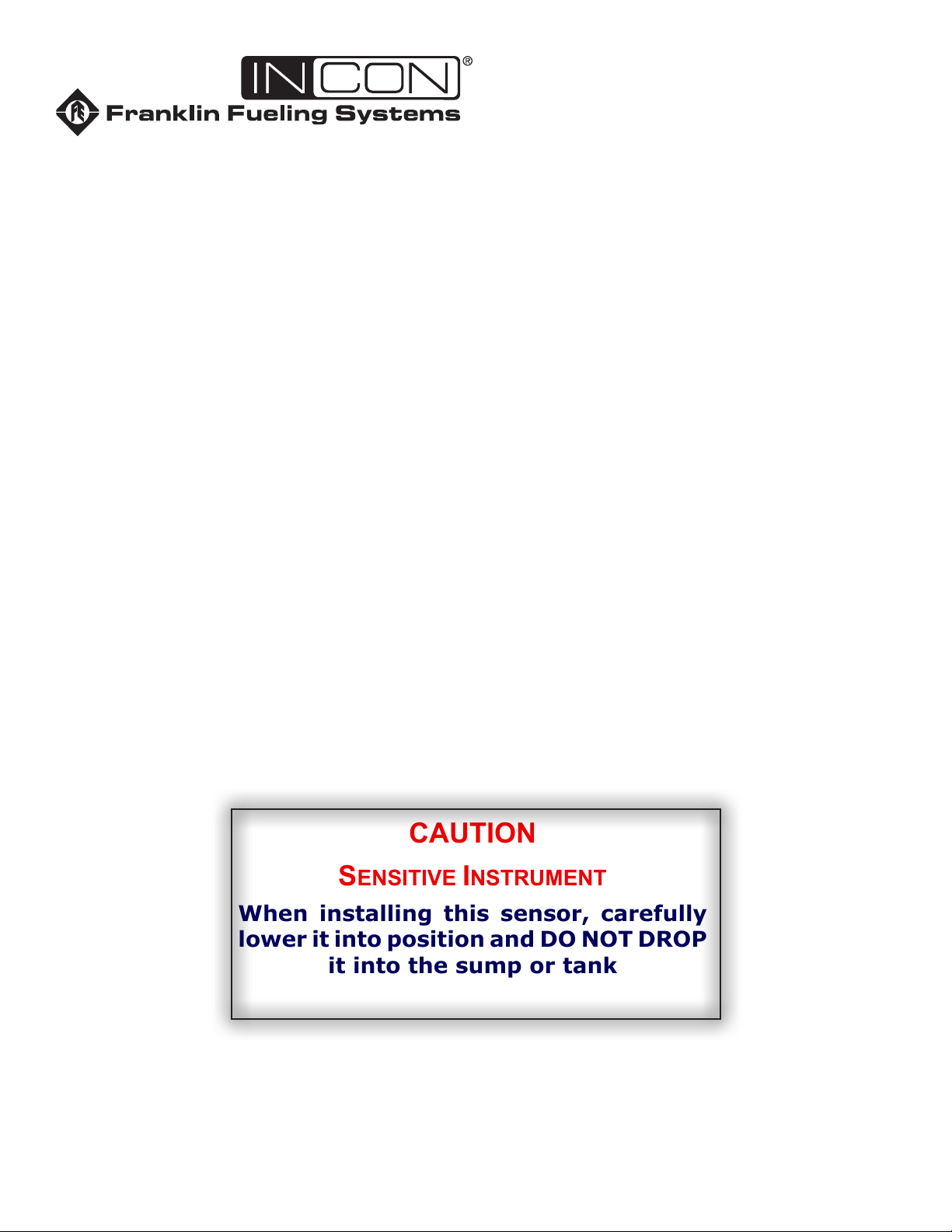
Magnetic
Reed float switch
opens when float
moves up 0.52 inch
(13.2 mm)
(Wht)
(Blk)
(Wht)
(Blk)
Typical Sensor Input
Interface (Channel N):
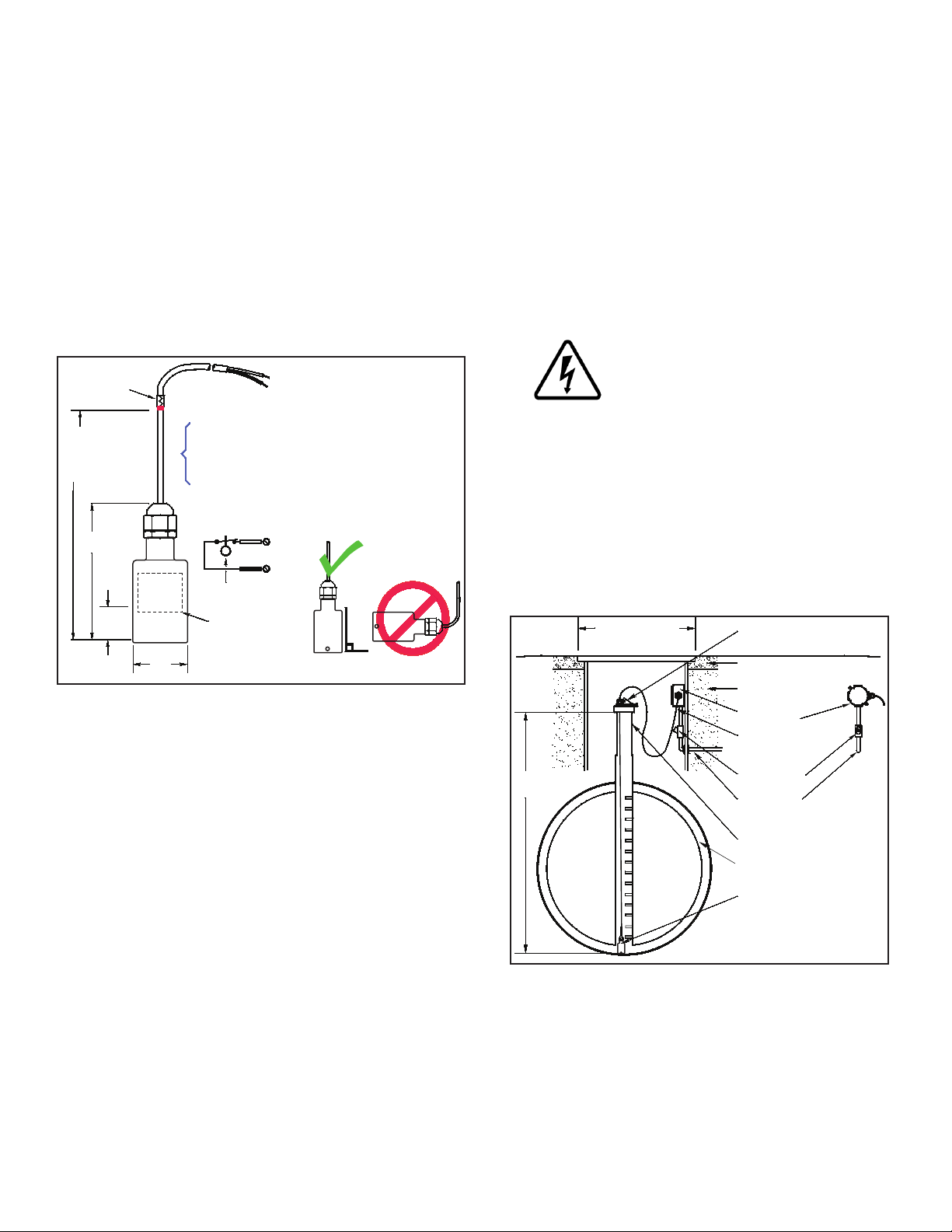
For installation in double-walled steel tanks, the
install height is measured from the top of the riser
to the bottom of the interstitial space in the tank
1.48
(37.6 mm)
0.52
(13.2 mm)
3.62
(92 mm)
C NC
Install Height =
Measured height
+1.5 inch (38.1 mm)
allowance for
TSP-K12 height
Colored
marking
pen/tape
Gnd
In
Suspend Sensor Veritcally
The TSP-ULS is a Standard sensor that is used to detect
the presence of a liquid in the normally dry Class 1, Division
1, Group D Hazardous Areas of: sumps, dispenser-pans,
and interstitial areas of double-wall steel storage tanks.
The sensor is supplied with electrical connectors, 25 feet of
cable, and a cord-grip tting (see diagrams). The TSP-ULS
uses magnetic-oat/reed-switch technology (the sensor
must be suspended vertically (See Figure 1) so the oat
can rise freely with the level of a liquid).
When the oat rises more than 1/2 of an inch, the
magnetically sensitive reed switch will open (see internal
oat in Figure 1). An open circuit is recognized as an alarmcondition at the intrinsically safe (I.S) leak detection circuits
of the FFS (Franklin Fueling Systems) ATG console.
• *TSP-KI2 Riser Cap for 2-inch riser pipes, includes a
pre-installed 1/2 inch NPT compression gland (cord grip)
tting. Other riser caps are available for different riser
pipe sizes – consult your factory rep.
• * Riser pipe – 2 inch diameter (OD), threaded at one end
(NPT-14) with all rough edges removed / deburred from
the inner edges.
* = Needed for installation in UST interstitial areas (Figure 2)
Installation Sequence
1. Install Riser Pipe, Manhole.
2. Install conduit, EYS ttings, and weatherproof
junction box.
3. Shut off power.
ELECTRICAL DANGER Avoid electrical
shock hazards: ensure all power
going to the ATG console is turned off,
tagged, and locked-out at the power
panel before doing any maintenance or
installation work at the ATG console.
4. Interstitial installation – see Figure 1 & 2, measure
the INSTALL HEIGHT needed and add 1.5 inches
= total height. Mark the total height on the sensor
cable as shown in Figure 1, pull the cable through
the TSP-KI2 Riser Cap and cord-grip until the mark
shows at the top of the cord grip tting. Tighten the
tting and lower the sensor into the interstitial area
of the tank as shown in Figure 2.
Materials Required
• Optional – TSP-DB1 Epoxy Seal kit for no-strip electrical
connectors – recommended for sites: within ood zones,
high groundwater tables, with poor drainage, or when
junction boxes are not used.
• 1/2 or 3/4 inch NPT (National Pipe Thread, tapered),
Rigid Metal Conduit (RMC) or nonmetallic (PVC) conduit
if allowed by local codes.
• EYS Seal ttings and Epoxy to ll the tting after
operational testing is completed.
• Weatherproof junction Box, gasket, and cover, plus a
3/4 to 1/2 inch NPT reducing bushing if 1/2 inch RMC is
used – see the ATG Installation Guide for recommended
electrical Junction Boxes.
• Wire: THHN, TFFN or THWN, 18 AWG, White & Black,
or Alpha Cable # 58411, 0.114 O.D. – 1,500 feet (457
meters) max. length. Alpha cable #58411 must be use
with nonmettalic conduit.
• Slip joint pliers to seat the no-strip, self-sealing wire
connectors – connectors are supplied with the sensor.
• UL Classied Thread Sealant or pipe dope.
2
Figure 1: TSP-ULS Dimensions
TSP-K
I
2 riser cap
(with cord grip - compression fitting)
Concrete slab
per NFPA 30
Clean fill material
(Gravel typical)
Weatherproof
Junction box
Compression
fitting (Cord grip)
Eys seal Fitting
1/2 or 3/4 inch conduit
2 inch riser pipe
Interstitial area (dry)
TSP-ULS
Sensor
Install height
(as measured)
Double-wall
steel tank
Cover for
14 inch (35.56 cm)
Min. dia. manhole
Manhole
Figure 2: Installation in Double-Walled Steel Tanks
5. Pull the sensor cable through the cord grip tting at
the junction box (also see Figure 3 for installation
within a sump) and tighten all remaining cord-grip
ttings. Trim wire / cables to a 6 or 8 inch (15 or
20 cm) service-loop, and splice the sensor and
console cable/wires together as shown in Figure 4.
Page 3

sump/dispenser pan and cover
Weatherproof
junction box
eys (epoxy-
filled)
1/2 or 3/4 inch
rigid metal
conduit
to ATG
console
y seal
fitting
TSP-ULS
Figure 3: Installation in Sumps / Dispenser Pans
6. Power up Console for next step.
7.
Test sensor (verify that an alarm is produced at ATG
console), if it does produce an alarm, seal EYS seal
ttings and electrical connectors with epoxy.
8. Turn off power again if other devices are to be
installed (Repeat Step 3).
9. Reinstall all safety covers and guards, junction
box gasket and covers – use pipe-dope to seal all
tting threads.
10. Install the manhole cover.
11. Record the location where the sensor was
installed on the chart on the last page of these
instructions. This information will be needed when
programming the ATG.
12. Turn on power and program the ATG – Ref: all
relating to Sensors in the Setup / Programming
Guide manual.
General Installation Notes
* Steel double-walled tanks are equipped with a pipe
that allows direct access to the bottom of the interstitial
(annular) space. When installing a riser pipe in a steel
tank, codes may require a non-conductive isolation
bushing be installed between the tank and riser pipe.
Warning
* Fill the bottom of the manhole with crushed stone to
facilitate drainage when the TSP-ULS is installed in the
interstitial space of a steel tank. Do not cover the top of the
riser with ll material, it must remain accessible for service
and for sensor installation.
Plan your conduit routing. Dig trenches as necessary to
install rigid threaded conduit (RMC) from each manhole
junction box to the Intrinsically Safe (I.S.) knockouts at the
ATG console. The conduit may enter the manhole either
from its bottom or through its side. A junction box inside
of the building as a pull box to combine several sensor
cables. If this is done, then only one I.S. conduit knockout
will be used.
It is the installer’s responsibility to
comply with all applicable federal, state
and local codes. Failure to do so may
create an Environmental Hazard.
Conduits must have EYS seal ttings
Warning
installed in accordance with NFPA
70 (National Electric Code) and NFPA
30A (Automotive and Marine Service
Station Code). Failure to seal conduits
in accordance with NFPA 30A, and
NFPA 70 could allow ammable vapors
to travel through the conduit in the
ATG console. An explosion could
result causing serious injury, property
loss, or death.
You must install a weatherproof, electrical junction
box inside each manhole. The junction box should be
installed high on the manhole wall to prevent it from being
submerged during heavy rains.
Caution
Seal all threaded ttings and conduit
threads to produce a weatherproof seal
during installation/maintenance.
Electrical Wiring
PWR(RED)
IN(WHT)
SENSOR 1
GND(BLK)
PWR(RED)
IN(WHT)
GND(BLK)
SENSOR N
Note: The
PWR (red)
terminal is
not used with
2-wire sensors
2 wires/cable from console
2-conductor cable from sensor
J-box
From 2-wire sensor
IN
(WHT)
Insert the unstripped wires fully
into the self-sealing, no-strip
electrical connector.
Use slip-joint pliers and seat
the black portion to make a
good electrical connection
GND
(BLK)
Figure 4: TSP-ULS Wiring
Reference the ATG Installation Manual and see Figure 4
(above) for TSP-ULS sensor wiring details. The two-wire
TSP-ULS sensor does not have a red (power) conductor,
therefore, the PWR (RED) interface terminal at the console
is not used. When a 3-conductor Alpha cable is used, the
red conductor can be clipped or taped back on both ends.
Testing the TSP-ULS
Testing this device is a matter of rotating the sensor 180
degrees with the bottom up, to cause an alarm at the ATG
console. Test the sensor for proper operation on a yearly
basis, or more frequently per local code.
3
Page 4

Record Sensor Location
Sensor Channel # / Notes
©2011 FFS 000-1346 Rev F
 Loading...