

Page 1

TSP-UHS Universal Hydrostatic Sensor
Magnetic Reed Float Switch
opens when float moves
down 0.75” (19 mm)
N.C.
Normal Liquid Level
Installation Instructions
Figure 1: TSP-UHS Overview
Overview
The TSP-UHS is a Standard sensor that is used to detect
the loss of a liquid in the normally solution-lled sensor
reservoir connected to the interstitial areas of double-wall
dispenser sumps. The sensor is supplied with electrical
connectors, 25 feet of cable, and a cord-grip tting (see
diagrams). The TSP-UHS uses magnetic-oat / reed-switch
technology (the sensor must be suspended vertically so
the oat can freely follow the level of a liquid).
When the oat drops more than 3/4 of an inch, the
magnetically sensitive reed switch will open. An open
circuit is recognized as an alarm-condition at the
intrinsically safe (I.S) leak detection circuits of the FFS
(Franklin Fueling Systems) ATG console.
Testing the TSP-UHS
This device can be tested by lifting the sensor from the
sensor reservoir. This will cause an alarm at the ATG
console. Test the sensor for proper operation on a yearly
basis, or more frequently per local code.
1
Materials Required
Optional: TSP-DB1 Epoxy Seal kit for no-strip electrical •
connectors – recommended for sites: within ood zones,
high groundwater tables, with poor drainage, or when
Junction Boxes are not used
1/2 or 3/4 inch NPT (National Pipe Thread, tapered), •
Rigid Metal Conduit (RMC) or nonmetallic (PVC) conduit
if allowed by local code
EYS Seal ttings and Epoxy to ll the tting after •
operational testing is completed (as required).
Weatherproof Junction Box, gasket, and cover, plus •
a 3/4 to 1/2 inch NPT reducing bushing if 1/2 inch
RMC is used. Refer to the ATG Installation Guide for
recommended electrical Junction Boxes
Wire: THHN, TFFN or THWN, 18 AWG, White & Black, •
or Alpha Cable # 58411, 0.114 O.D., 1,500 feet (457
meters) max. length. If using nonmetallic (PVC) conduit,
Alpha Wire P/N 58411 (2.8 mm) 0.112” O.D. must be
used (INCON P / N 600-0062).
Slip joint pliers to seat the no-strip, self-sealing wire •
connectors. Connectors are supplied with the sensor
• UL Classied Thread Sealant or pipe dope.
Page 1 of 2
Page 2
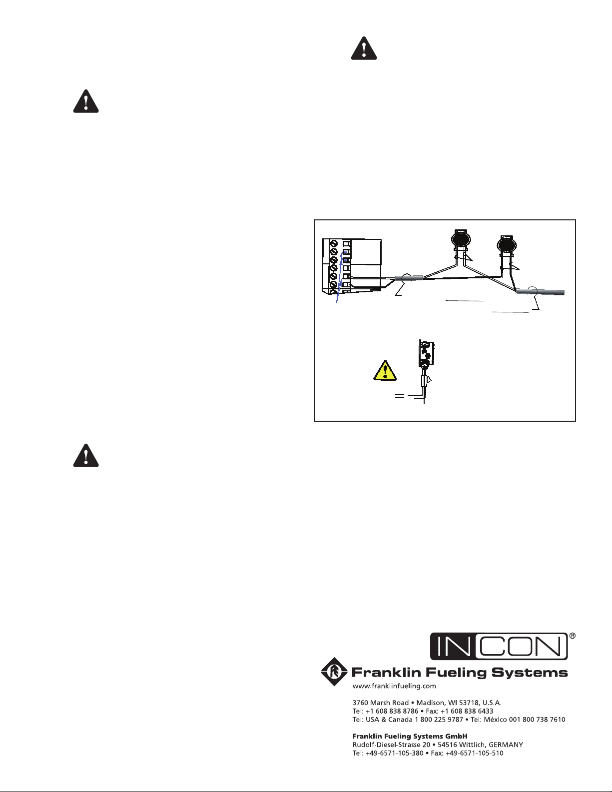
Installation Sequence:
2 wires/cable from console
2-conductor cable from sensor
J-box
From 2-wire sensor
SENSOR N
IN(WHT)
Only remove the
jumper link between:
in (wht) & gnd (blk),
when a sensor
channel is wired
Note: The
PWR (red)
terminal is
not used with
2-wire sensors
GND(BLK)
PWR(RED)
PWR(RED)
SENSOR 1
IN(WHT)
GND(BLK)
Insert the unstripped wires fully
into the self-sealing, no-strip
electrical connector.
Use slip-joint pliers and seat
the black portion to make a
good electrical connection
IN
(WHT)
GND
(BLK)
1. Install Conduit, EYS ttings, and Weatherproof
Junction Box.
Mechanical installation
Warning
2. Pull the sensor cable through the cord grip tting
at the Junction Box and tighten all remaining cord-
grip ttings. Trim wire/cables to a 6 or 8 inch (15
or 20 cm) service-loop, and splice the sensor and
console cable/wires together.
3. Power up Console for next step
4. Test sensor (verify that an alarm is produced at
ATG console), if it does produce an alarm, seal
EYS seal ttings and electrical connectors with
epoxy – Electrical installation
5. Turn Off Power again if other devices are to be
installed.
6. Reinstall all safety covers and guards, junction box
gasket and covers. Use pipe-dope to seal all tting
threads.
7. Record the location where the sensor was
installed.
8. Turn On Power and Program the ATG. Refer
to all sections relating to sensors in the Setup/
Programming Guide manual: Service Technician
setup.
General Installation
Warning
Plan your conduit routing. Dig trenches as necessary
to install conduit from each manhole junction box to the
Intrinsically Safe (I.S.) knockouts at the ATG console. A
junction box inside of the building as a pull box to combine
several sensor cables. If this is done, then only one I.S.
conduit knockout will be used.
Electrical shock hazards: ensure all
power going to the ATG console is
turned off, tagged, and locked-out
at the power panel before doing any
maintenance or installation work at the
ATG console
It is the installer’s responsibility to
comply with all applicable federal, state
and local codes. Failure to do so may
create an Environmental Hazard.
Warning
installed in accordance with NFPA
70 (National Electric Code) and NFPA
30A (Automotive and Marine Service
Station Code). Failure to seal conduits
in accordance with NFPA 30A, and
NFPA 70 could allow ammable vapors
to travel through the conduit in the
ATG console. An explosion could result
causing serious injury, property loss,
or death.
You must install a weatherproof, electrical junction
box inside each manhole. The junction box should be
installed high on the manhole wall to prevent it from being
submerged during heavy rains.
Conduits must have EYS seal ttings
Figure 2: Splice Connection
Seal all threaded ttings and conduit threads to produce a
weatherproof seal during installation/maintenance.
Electrical Wiring
The two-wire TSP-UHS sensor does not have a red
(power) conductor, therefore, if there is a PWR (RED)
interface terminal at the console, it is not used. When a
3-conductor Alpha cable is used, the red conductor can be
clipped or taped back on both ends.
If installing in a Phil-Tite double-wall dispenser sump, refer
to Franklin Fueling Systems instructions 602019026.
©2008 FFS 000-1389 Rev B
2
 Loading...