

Page 1

TSP-MWS
(Discriminating Monitoring Well Sensor BriteSensor®)
Installation Instructions
Franklin Fueling Systems • 3760 Marsh Rd. • Madison, WI 53718 USA
Tel: +1 608 838 8786 • 800 225 9787 • Fax: +1 608 838 6433 • www.franklinfueling.com
Page 2
Overview
TSP-MWS
Discriminating
Monitoring well
Sensor
(Britesensor ®)
Sensor
Model-lengths:
TSP-MWS-10 =
10 foot length (3 m)
TSP-MWS-15 =
15 foot length (4.6 m)
TSP-MWS-20 =
20 foot length (6 m)
TSP-MWS-25 =
25 foot length (7.6 m)
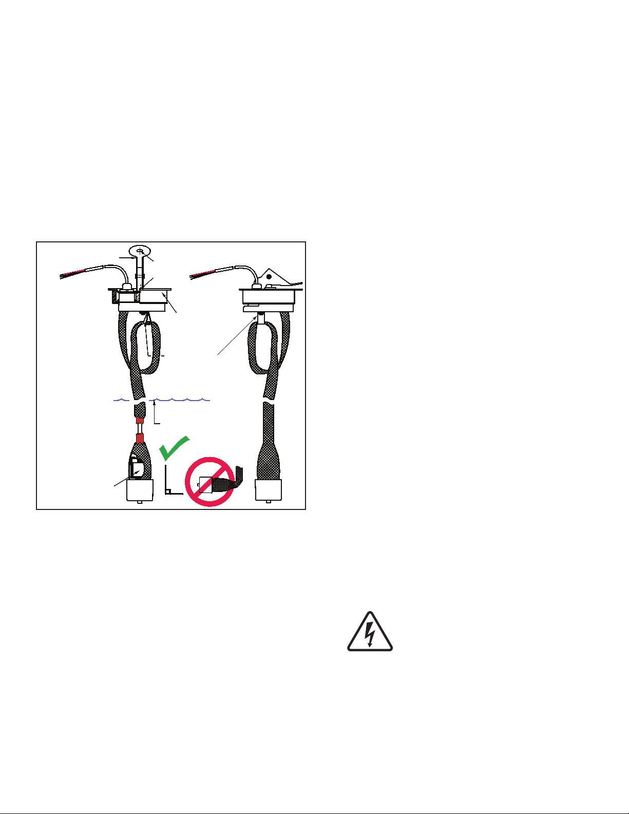
Sensor must be installed
“suspended in groundwater”
4 inch (102 mm)
Locking riser cap
(part of sensor)
Retainer to loop
excess sensor length
Dry season groundwater level
Internal
low water level
float switch
Lever
Thru holes
For locking
The TSP-MWS sensor is an intelligent BriteSensor ® that
is used to monitor groundwater for the presence of liquid
hydrocarbons (product).
These sensors are installed suspended in the groundwater
of monitoring wells around tanks and use intrinsically safe
(I.S) leak detection circuits – approved for use in these
Class 1, Division 1, Group D Hazardous Areas.
The TSP-MWS sensors have a oat at the base that
monitors for the presence of ground water—a dry sensor
cannot detect liquid hydrocarbons that oat on the surface
of groundwater. The sensors also have a conductive
polymer strip along its length, which reacts specically with
liquid hydrocarbons (causing an increase in the electrical
resistance of the polymer strip).
Like other BriteSensors, The TSP-MWS sensors have a
microprocessor that analyzes the environmental conditions
at the sensor and transmits this data to the Automatic
Tank Gauge console. The TSP-MWS sensors detect and
communicates:
A dry well alarm (from the oat at its base), •
PRODUCT present (from the polymer strip),•
NORMAL no-alarm state (no product present and •
sensor is submerged in groundwater),
Plus it transmits a specic sensor ID code.•
An attached 4 inch riser cap, no-strip electrical wire
connectors, 25 feet of cable attached to the sensor, a
Model ID tag, and a cord-grip tting (for connection to a
weatherproof electrical junction box) are supplied with the
TSP-MWS sensor (see diagrams).
2
Figure 1: TSP-MWS Sensor Dimensions
Testing the Sensor
Turn the bottom of the sensor up 180 degrees so the
bottom faces up, wait 5 seconds, and let the sensor
hang dry again – a DRY WELL alarm will be generated.
Although sensors may be washed and recovered after
exposure to liquid hydrocarbons, we recommend not
testing for product alarms because of the long after-test
recovery period involved.
Test sensors on a yearly basis, or more frequently if
required by local code.
Test the groundwater for the presence of liquid
hydrocarbons BEFORE installing the monitoring well
sensor (give copy of results to site owner / manager).
Materials Required
Optional – TSP-DB1 Epoxy Seal kit for no-strip electrical •
connectors – recommended for sites: within ood zones,
high groundwater tables, with poor drainage, or when
Junction Boxes are not used.
Well Screen Pipe – Schedule 40 PVC, 4 inch (102 mm) •
diameter.
1/2 or 3/4 inch NPT (National Pipe Thread, tapered), •
Rigid Metal Conduit (RMC) or nonmetallic (PVC) if
allowed by local code.
EYS Seal ttings and epoxy to ll the tting after •
operational testing is completed.
Weatherproof junction box, gasket, and cover, plus a •
3/4 to 1/2 inch NPT reducing bushing if 1/2 inch RMC is
used – see the ATG Installation Guide for recommended
electrical Junction Boxes.
Wire: THHN, TFFN or THWN, 18 AWG: Red, White, & •
Black, or Alpha Cable # 58113,(3.3 mm) 0.131” O.D. –
1,500 feet (457 meters) max. length. Alpha cable 58113
must be used if using non-metallic (PVC) conduit.
Slip joint pliers to seat the no-strip, self-sealing wire •
connectors – connectors are supplied with the sensor.
U.L. classied thread sealant or pipe dope.•
Installation Sequence
1. Install Sump.
2. Install conduit, EYS ttings, and weatherproof
junction box.
3 Shut off power.
ELECTRICAL DANGER Avoid electrical
shock hazards: ensure all power
going to the ATG console is turned off,
tagged, and locked-out at the power
panel before doing any maintenance or
installation work at the ATG console.
4. Install the sensor cable through the supplied
compression tting.
5. Install the compression tting at the waterproof
junction box and tighten the cord-grip tting.
6. Trim wire/cables at the junction box to a 6 or 8 inch
length (15 or 20 cm) or service-loop, and splice the
sensor and console wires together per Figure 3.
Page 3

7. Turn power on to console to test sensor.
Cover for
14 inch (35.56 cm)
min. dia. manhole
Manhole
EYS seal fitting
½ or ¾ inch conduit
Loop extra
Sensor length
On retainer
Dry season groundwater level
4 inch (102 mm) pvc
monitoring well screen pipe
Concrete slab per NFPA 30
Weatherproof
Junction box
Compression
Fitting (cord grip)
Clean fill material
(Gravel typical)
TSP-MWS-XX
With riser cap
TO 3-W I RE SENSOR
3 W IRE S/CA BLE FROM CONS OLE
3-C ONDUCTO R CABLE FROM SENSOR
SENSOR N
IN(WHT)
Only remove the
j
umper link between:
IN (wht) & GND (blk),
wh en a sensor channel is wired
Note: The PWR (red) terminal
is only used wi th 3-w ire sensors
GND(BLK)
PWR(RED)
PWR(RED)
SENSOR 1
IN(WHT)
GND(BLK)
Insert the unstripped w ires
fully into the self-sealing,
no-strip electrical connector.
Use slip-joint pliers and
seat the black portion
to
make a good electrical connection
GND
(BLK)
PWR
(RED)
IN
(WHT)
Caution
Warning
Caution
Warning
8. Test sensor (verify that an alarm is produced at
ATG console), if it does produce an alarm, seal
EYS seal ttings and electrical connectors with
epoxy.
9. Turn power off again if other devices are to be
installed (Repeat Step 3).
10. Install the TSP-MWS sensor in the well screen
pipe and latch the riser cap (ref. Figure 1 & 2).
A junction box may be used inside of the building and used
as a I.S. pull box to combine several sensor cables. If this
is done, then only one I.S. conduit knockout may be used
at the console. Before pulling wires, mark them to avoid
confusion when connecting to the console.
Conduits must have EYS seal ttings
installed in accordance with NFPA
70 (National Electric Code) and NFPA
30A (Automotive and Marine Service
Station Code). Failure to seal conduits
in accordance with NFPA 30A, and
NFPA 70 could allow ammable vapors
to travel through the conduit in the
ATG console. An explosion could result
causing serious injury, property loss,
or death.
CAUTION Seal all threaded ttings and conduit threads to
produce a weatherproof seal during installation.
11. Reinstall all safety covers and guards, junction
box gasket and covers – use pipe-dope to seal all
tting threads.
12. Install the manhole cover.
13. Record the location where the sensor was
installed (Tank #,Sensor Channel #, and other
data) on the table on the back page of these
instructions.
14. Turn power on and program the ATG – Refer
to Sensors in the ATG Setup / Programming &
Installation manuals.
General Installation Notes
Plan your conduit routing. Dig trenches as necessary to
install conduit from each junction box to the Intrinsically
Safe (I.S.) knockouts at the ATG console. You must install
a weatherproof, electrical junction box inside each sump.
Access to sumps must be done so all entries are liquidproof (to keep product in the sump if a spill or leak occurs).
The junction box should be installed high on the sidewall to
prevent it from being submerged during heavy rains.
Figure 2: TSP-MWS Installation
It is the installer’s responsibility to
comply with all applicable federal, state
and local codes. Failure to do so may
create an Environmental Hazard.
Figure 3: Sensor Wiring
Electrical Wiring
Reference the ATG Installation Manual and see Figure 3
(above) for TSP-MWS sensor wiring details.
3
Page 4

Tank # Notes
©2008 FFS 000-1349 Rev D
 Loading...