


Tank Sentinel
Tank Sentinel
®
Installation
(TS-2001, TS-1001, TS-508, TS-504 & TS-750)
Automatic Tank Gauge
/
Leak Detection
System
TANK SENTINELTS-1001
Guide
INCON Part Number: 000-1050 Rev. E
Copyright © January 2004
Printed in the U.S.A.
TANK SENTINEL® INSTALLATION GUIDE
NOTICE
INCON has strived to produce the finest possible manual for you, and to ensure
that the information contained in it is complete and accurate. However, INCON
makes no expressed or implied warranty with regard to its contents. INCON
assumes no liability for errors or omissions, or for any damages, direct or
consequential, that result from the use of this document or the equipment which it
describes.
This document contains proprietary information and is protected by copyright. All
rights are reserved. No part of this document may be reproduced in any form
without the prior written consent of INCON.
INCON reserves the right to change this document at any time without notice.
Use the Table of Contents to find topics within this manual.
Need Help ? Mail Address (no packages):
INTELLIGENT CONTROLS INC
PO BOX 638
SACO ME 04072
Office Hours: 8 am to 5 pm EST, Monday through Friday
Sales – Orders 24 hour Technical Service
Delivery Schedules: RMA, Application Help:
Fax: (207) 283-0158 Fax: (207) 282-9002
Phone: (800) 872-3455 Phone: (800) 984-6266
+207 283 0156 +207 283 0156
email: sales@incon.com email: tech@incon.com
INCON is a wholly owned subsidiary of Franklin Electric and is member of the:
Franklin Fueling Systems Group. Visit our web site at:
Tank Sentinel®BriteSensors® and INCON®are registered trademarks of Intelligent Controls, Inc.
System Sentinel™ and System Sentinel
LS300 Auto-Learn
®
is a registered trademark of FE Petro
Copyright© 2004 – all rights reserved.
™ are trademarks of Intelligent Controls, Inc.
www.franklinfueling.com
®
.
TANK SENTINEL® INSTALLATION GUIDE

Contents
P Preface.................................................................................................P-1
Graphic Symbol Conventions..................................................................................... P-1
1 Installation Overview........................................................................... 1-1
Product Description — TS-504 ...................................................................................1-3
Product Description — TS-508 ...................................................................................1-3
Product Description — TS-750 ...................................................................................1-4
Product Description — TS-1001 .................................................................................1-5
Product Description — TS-2001 .................................................................................1-6
2 Riser Pipes & Manholes ..................................................................... 2-1
3 Tank Measurements............................................................................ 3-1
4 Console Mounting............................................................................... 4-1
Console Location.........................................................................................................4-1
5 Conduit and Junction Boxes ............................................................. 5-1
6 Level Probe Installation ...................................................................... 6-1
7 System Wiring ..................................................................................... 7-1
8 System Start-up................................................................................... 8-1
9 Initial System Programming............................................................... 9-1
10 Service, T roubleshooting Guide, Warranty................................... 10-1
Troubleshooting Guide..............................................................................................10-6
#1 — No Display Readout...................................................................................10-6
#2 — Keypad Not Responding............................................................................10-6
#3 — Programmed Setup Lost when Power is Lost ...........................................10-6
#4 — Printer Doesn’t Print ..................................................................................10-6
#5 — Inaccurate Levels.......................................................................................10-6
#6 — NO PROBE DETECTED is Displayed.......................................................10-7
#7 — PROBE SYNC is Displayed.......................................................................10-7
#8 — FLOAT MISSING is Displayed...................................................................10-7
#9 — Continuous or Repeating Theft Alarms......................................................10-8
#10 — Delivery Alarms — Multiple Low Level Alarms.........................................10-8
#1 1 — Audible Alarms not Working.....................................................................10-8
#12 — False Deliveries Reported .......................................................................10-8
#13 — Multiple Delivery Reports.........................................................................10-8
#14 — Multiple Sensor Alarms............................................................................10-8
#15 — Verify System Operation..........................................................................10-9
Appendix A System Technical Specifications ...............................A-1
Appendix B Control Drawing .............................................................. B-1
FCC Information & Requirements...................................................FCC-1
Addendum to TS-1000, TS-1001, & TS-2001 Manuals .............................. back cover
TABLE OF CONTENTS Page TOC - 1
TOC
P PREFACE
— Important – Read
Read and follow the entire instructions in this manual before installing or working on
this equipment.
Certified Installer/Service Person: Only an INCON certified installer or service
person is allowed to access both the user interface kepad and areas internal to the
Tank Sentinel™ console.
Station Owner/Operator: The station owner or operator of the Tank Sentinel™
console is only allowed to access the user interface keypad. Access to areas
internal to the console is strictly prohibited.
Graphic Symbol Conventions
NOTE
Important information, tips, and hints are highlighted by the note graphic.
CAUTION messages are highlighted by the CAUTION graphic and contain
instructions that should be followed to avoid faulty equipment operation, or
environmental hazards, or personnel injury!
WARNING
instructions that must be followed to avoid faulty equipment operation or explosion.
If ignored, severe injury or death may result!
DANGER
instructions that must be followed to avoid an explosion or fire hazard. If ignored,
severe injury or death will result!
ELECTRICAL DANGER
DANGER graphic and contain instructions that must be followed to avoid an
electrical shock. If ignored, severe injury or death may result and even severe
damage to electronic equipment.
messages are highlighted by the WARNING graphic and contain
messages are highlighted by the DANGER graphic and contain
messages are highlighted by the ELECTRICAL
Earth Ground Terminal
Ground Terminal
Single Phase Alternating
Current
PREFACE Page P - i P
Read this – Before you Begin
Product Legend (codes used in this manual):
T1
= for TS-1001 UST Tank Sentinel® ATG and Leak Detection System
T2
= for TS-2001 UST Tank Sentinel® ATG and Leak Detection System
T4
= for TS-504 AST Tank Sentinel® Inventory Monitoring System
T7
= for TS-750 UST Tank Sentinel® Tank Monitoring and Compliance Kit
T8
= for TS-508 UST Tank Sentinel® Inventory Monitoring System
none
= for all products
Abbreviations (used in this manual):
NOTE
AST
UST
ATG
I.S.
Unlike the TS-2001 (
TS-504 (T4) are Inventory Monitoring systems that don’t support tank leak-testing,
or line leak-testing (leak-detection sensors can be interfaced with optional TS-SEM
modules).
CAUTION
Tank Sentinel®console may be installed in hazardous locations where flammable
vapors are present. It is essential that you read and follow all warnings and
instructions in this manual carefully to protect yourself and others from: injury,
electrical shock, explosion, and death.
The Tank Sentinel® system is designed using principles of intrinsic safety. The
power in the wiring between the console and the liquid level probe and the leak
detection sensors is limited to a very low level. It is not possible for the electrical
energy available in this wiring to cause ignition of group D flammable vapors
system (ATG console, probes and sensors) have been properly installed and wired.
It is your responsibility to maintain the effectiveness of the safety features by
following the instructions in this manual. You can create a serious explosion hazard
by installing or wiring this system incorrectly.
= for Aboveground Storage Tanks
= for Underground Storage Tanks
= for Automatic Tank Gauge
= for Intrinsically Safe
T2)
, TS-1001 (T1) and TS-750 (
The probes and leak detection sensors that are connected to the
T7)
, the TS-508 (T8) and
if
the
Leaking underground storage tanks – USTs – create serious environmental
and health hazards. The (
detect leaks in these tanks. You must follow the instructions in this manual
carefully to ensure that the system will be effective in detecting these leaks
and hazards.
P Page P - ii TANK SENTINEL INSTALLATION GUIDE
T1, T2, T7
) Tank Sentinel® system is designed to

1 Installation Overview
Product Codes:
none = all products
T1
= TS-1001, T2 = TS-2001, T4 = TS-504, T7 = TS-750, T8 = TS-508,
Before You Get Started
It is important to follow the instructions in this manual. They have been prepared to
help you install the Tank Sentinel
and effectively. Please read the entire manual carefully. Failure to follow the
instructions in this manual can result in faulty operation, equipment damage, injury,
or death. This equipment must be installed, programmed, and serviced by factorytrained & certified technician. Failure to comply will void the system warranty.
Contents of this Manual
This manual contains installation and site preparation instructions for the INCON
Tank Sentinel system, which includes the console, level probes, and concise
instructions for leak detection sensors. The overall safety issues, troubleshooting
guide, warranty, service, and return policy — as defined in this manual — must be
followed.
Where to Find Information
®
system successfully, so that it will operate safely
The system operation and programming instructions, troubleshooting guide and
console maintenance, are contained in separate manuals or Quick Reference
Guides. Detailed installation and testing instructions for each type of leak detection
sensors are contained within separate manuals. Likewise, the installation, testing,
and programming of various upgrade kits and optional accessories (such as
the: TS-RA2 Remote Overfill Alarm and TS-RK Remote Alarm Acknowledge Unit)
are also contained in separate manuals or addenda.
Questions about the installation of the system, or this manual, should be directed
to INCON, P.O. Box 638, Saco, Maine 04072. Please address all inquiries to our
Technical Service Department, or call one of our Service Technicians toll free at
1-800-984-6266
(+207 283 0156)
INSTALLATION OVERVIEW Page 1 - 1 1
Safety Instructions
CAUTION
Read the installation instructions carefully. The Tank Sentinel
system is designed to be safe when correctly installed. It is possible to create
explosion hazards, health hazards, risk of death, and environmental hazards
through incorrect installation.
CAUTION
You must comply with state and local electrical codes as well as
the your National Electrical Code (U.S.A. – NFPA 70) and Automotive and Marine
Service Station Code (U.S.A. – NFPA 30A), or Canadian Electric Code (as
applicable), when installing the Tank Sentinel system.
WARNING
When the Tank Sentinel system is used to monitor tanks containing
gasoline or other flammable substances, you may create an explosion hazard if you
do not follow the requirements of this manual carefully.
ELECTRICAL DANGER
All wiring must enter the Tank Sentinel enclosure
through the designated knockouts. An explosion hazard may result if other
openings are used.
ELECTRICAL DANGER
You must run wiring from probes or sensors to the
Tank Sentinel console in conduits which are separate from all other wiring. Failure
to do so, will create an explosion hazard.
WARNING
Do not install the Tank Sentinel console in a flammable or
explosive hazardous location. An explosion could result.
ELECTRICAL DANGER
Make sure that AC line power to the console is
turned off during installation or maintenance. Lethal voltages are present inside the
console which could injure or kill you.
WARNING
Substitution of components could impair intrinsic safety. The Tank
Sentinel system is intrinsically safe for probes or sensors installed in – Class I,
Division 1, Group D – hazardous locations. Substitution of components could make
the energy limiting circuitry in the system ineffective. An explosion hazard could
result. Repairs to the Tank Sentinel system should be performed only by a
qualified, factory-trained technician.
1 Page 1 - 2 TANK SENTINEL
®
INSTALLATION GUIDE

Product Description — TS-504
The INCON Tank Sentinel model TS-504 (
inventory monitoring system for up to 4 aboveground storage tanks (ASTs). It
performs many important functions simultaneously. A basic TS-504 Automatic Tank
Gauge (ATG) consists of a wall-mounted console, inventory only liquid level probes
(
TSP-LL2-I
additional optional hardware and software upgrades that are available for the
system. The TS-504:
•
can display / printout in several languages (English, French, Spanish, Portuguese)
NOTE that an
•
monitors deliveries, inventory levels, thefts, and other conditions (such as: high
water levels, low product levels, reorder product levels, and full and over-full
product levels)
•
generates reports automatically in response to preset/programmed conditions and
alarms
•
provides audio / visual annunciation when an alarm or warning condition exists
•
enhances site-management by increasing efficiency, and by providing the data to
make intelligent business choices
one for each tank), and probe installation kits. There are many
optional
printer is required for local printing of reports
T4
) is an automatic and continuous
•
interfaces with external audio/visual alarms with two form-C relay outputs (std)
•
communicates to external locations in response to preset/programmed conditions
or alarms, and communicates bidirectionally during data acquisition if an
plug-in modem or fax-modem is installed inside of the console
•
detects external product leaks with
(see TABLE 1.2)... up to 8 sensors can be wired internally, and an additional 8 or
16 sensors can be wired to 1 or 2 optional, external TS-SEM BriteBoxes (see
Chapter 7 about the TS-SEM)
•
monitors precise tank inventory and sales data when an
dispenser interface module is installed
•
can be mounted within a port-holed, Nema 4X enclosure (TS-NEMA4X)
Product Description — TS-508
The INCON Tank Sentinel model TS-508 (
inventory monitoring system for up to 8 aboveground storage tanks (ASTs). It
performs many important functions simultaneously. A basic TS-504 Automatic Tank
Gauge (ATG) consists of a wall-mounted console, inventory only liquid level probes
(
TSP-LL2-I
additional optional hardware and software upgrades that are available for the
system. The TS-508 includes all of the features shown previously in the TS-504
except that it can monitor 4 additional tanks, or 8 tanks total.
one for each tank), and probe installation kits. There are many
optional
T8
optional
, approved, leak detection sensors
optional
) is an automatic and continuous
TS-DIM
INSTALLATION OVERVIEW Page 1 - 3 1

Product Description — TS-750
The INCON Tank Sentinel model TS-750 (
T7
) is an automatic and continuous tank
monitoring system for up to 4 underground storage tanks (USTs). It performs many
important functions simultaneously. A basic TS-750 Automatic Tank Gauge (ATG)
consists of a wall-mounted console, liquid level probes (TSP-LL2 one for each
tank), and probe installation kits.
The TS-750:
•
can display / printout in several languages (English, French, Spanish, Portuguese)
•
monitors deliveries, inventory levels, thefts, and other conditions (such as: high
water levels, low product levels, reorder product levels, and full and over-full
product levels)
•
generates reports automatically in response to preset/programmed conditions and
alarms
•
provides audio / visual annunciation when an alarm or warning condition exists
•
enhances site-management by increasing efficiency, and by providing the data to
make intelligent business choices
•
interfaces with external audio/visual alarms with two form-C relay outputs (std)
•
communicates to external locations in response to preset/programmed conditions
or alarms, and communicates bidirectionally during data acquisition if an optional
external modem is installed
•
detects external product leaks with optional, approved, leak detection sensors (see
TABLE 1-2), up to 8 sensors can be wired internally
•
can be mounted within a port-holed, Nema 4X enclosure (TS-NEMA4X)
1 Page 1 - 4 TANK SENTINEL
®
INSTALLATION GUIDE

Product Description — TS-1001
The INCON Tank Sentinel model TS-1001 (
T1
) is a complete, automatic inventory
monitoring and leak detection system for up to 4 underground storage tanks. It
performs these important functions simultaneously. A basic TS-1001 Automatic
Tank Gauge (ATG) and Leak Detection System consists of a wall-mounted
console, magnetostrictive liquid level probes (one for each tank), and probe
installation kits. There are many additional optional hardware and software
upgrades that are available for the system. The TS-1001:
•
conducts highly accurate, 99.9% Pd @ 0.2 gph(0.76 lph), third-party approved, intank volumetric leak tests on demand or on an automatic schedule for EPA
compliance reporting (this helps prevent environmental contamination)
•
monitors deliveries, inventory levels, thefts, and other conditions (such as: high
water levels, low product levels, reorder product levels, and full and over-full
product levels)
•
generates reports automatically in response to preset/programmed conditions and
alarms
•
provides audio / visual annunciation when an alarm or warning condition exists
•
enhances site-management by increasing efficiency, and by providing the data to
make intelligent business choices
•
can display / printout in several languages (English, French, Spanish, Portuguese)
•
interfaces with external audio/visual alarms with two form-C relay outputs (std)
•
monitors up to 8 optional TS-LLD line leak detectors for EPA compliance reporting
and for positive pump shutdown when a leak is detected
•
communicates to external locations in response to preset/programmed conditions
or alarms, and communicates bidirectionally during data acquisition if an optional
plug-in modem / fax-modem is installed inside the console
•
provide positive, pump shutdown with an optional TS-ROM BriteBox
•
detects external product leaks with optional, approved, leak detection sensors (see
TABLE 1.2)... up to 12 sensors can be wired internally, and an additional 8 or 16
sensors can be wired to 1 or 2 optional, external TS-SEM BriteBoxes (see
Chapter 7 about the TS-SEM)
•
monitors precise tank inventory and sales data when an optional TS-DIM dispenser
interface module is installed
•
conducts statistical tank leak tests continuously for EPA compliance reporting
(useful in busy / 24 hour sites) with the optional SCALD software upgrade
•
monitors emergency generator sites and runs tank leak tests continuously for EPA
compliance reporting with the optional Generator software
• can be used for chemical applications with chemical probes. The TSP-LL2C is a
TSP-LL2 probe with Stainless Steel (SS): swagelock fitting, install kit, and float.
This list identifies many of the TS-1001 capabilities, but may not be all-inclusive.
INSTALLATION OVERVIEW Page 1 - 5 1

Product Description — TS-2001
The INCON Tank Sentinel® model TS-2001 (T2) is a complete, automatic inventory
monitoring and leak detection system for up to 8 underground storage tanks. It
performs these important functions simultaneously. A basic TS-2001 Automatic
Tank Gauge (ATG) and Leak Detection System consists of a wall-mounted
console, magnetostrictive liquid level probes (one for each tank), and probe
installation kits.
With the exception of the Emergency Generator application, the TS-2001 has the
all of the standard features of the TS-1001 but with increased liquid level probe and
leak detection capabilities (see the TS-1001 bullet points). The TS-2001 can
accommodate twice as many tanks and twice as many sensors (internally) than can
the TS-1001. See the TS-1001 bullet points for additional optional hardware and
software upgrades that are available with the TS-2001 system. The TS-2001 has:
•
8 or 16 internal I/O module add-on capability with the
Chapter 7 about the TS-IEM and available I/O modules for this PC-Board).
•
an increased number of sensor channels. It can monitor up to 24 leak detection
sensors internally (twice as many as the TS-1001). It can also monitor an
additional 8 or 16 leak detection sensors with 1 or 2
Expansion Modules (see Chapter 7 about the TS-SEM).
optional
optional
TS-IEM (see
, TS-SEM Sensor
Unpacking, Inspection, and Damage Claims
Unpack and thoroughly examine all components of the system as soon as they are
received. If the equipment appears to be damaged, write a detailed description of
the suspected damage on the face of the bill of lading and have the carrier’s agent
sign it.
Insist that the carrier’s agent review the damage and sign the description.
Immediately notify the carrier of the damage or loss by telephone. Confirm this
report in writing within 48 hours. It is important that you contact the carrier
immediately. Also report the damage to INCON Intelligent Controls, Inc. promptly,
so that we may assist you with your claim.
1 Page 1 - 6 TANK SENTINEL
®
INSTALLATION GUIDE
The risk of loss or damage to merchandise in shipping remains with the buyer. It is
the buyer’s responsibility to file and settle the claim with the carrier.
You must obtain a Return Material Authorization (RMA) number before returning
any equipment to INCON. See INCON Warranty Policy P/N 000-1197 about the
RMA procedure requirements. Shipments of returned material which have not
been authorized will be returned freight-collect.
Please have a pen and a piece of paper at hand when you call INCON – Technical
Service Department,1-800-984-6266 (+207 283 0156), for a Return Material
Authorization number. One of our Service Technicians will also give you the return
shipping address and shipping instructions.
Return Shipping Charges
Under Warranty
INCON will pay all freight and insurance charges for all “Under-Warranty” RMA’s.
Non-Warranty
It is the buyer’s responsibility to prepay all freight and insurance charges for NonWarranty RMA’s.
NOTE
Reference chapter 10 in this manual for Warranty issues.
Materials Required for this Installation
TABLE 1-1: Cables Required for Liquid Level Probes
The type of cable required for Liquid Level Probes is based on the length of
cable run from the probe to the Tank Sentinel console.
Cable Type Probe Model: TSP-LL2
Belden No. 87760 0.12” (3 mm) OD ............... 260 ft (80 M) maximum
Belden No. 87761 0.12” (3 mm) OD ..............400 ft (122 M) maximum
*
Belden No. 88761 0.12” (3 mm) OD .............. 400 ft (122 M) maximum
Belden No. 89182 0.31” (7.9 mm)OD ........... 1500 ft (450 M) maximum
*
Only use cable specified above – DO NOT exceed maximum
cable lengths. See probe label / shipping tube for Model, S/N, Gradient, etc.
You can order this cable from INCON
*
NOTE
Intrinsically safe (I.S.) probe cable(s) and leak detection
sensor wires/cables may be run together within the same
conduit.
INSTALLATION OVERVIEW Page 1 - 7 1

Cable or Wire for Leak Detection Sensors
Leak Detection Sensor Cable is required when NOT run through rigid metal
conduit. Reference the Direct Burial Cable – Installation Manual (P/N 000-1041) for
further information. See below for Cable type and description:
Alpha 58411 (INCON P/N 600-0062) Two conductor Cable for standard, 2 conductor
Leak Detection Sensors, 0.114” (2.9 mm) O.D.
Alpha 58113 (INCON P/N 600-0063) Three conductor Cable for 3 conductor
Leak Detection Sensors, 0.128” (3.3 mm) O.D.
Leak Detection Sensor Wire can be used when enclosed within rigid metal
conduit — from the sensor to the Tank Sentinel console:
3 Type THHN, TFFN, or THWN, Black, White, and Red,
18 AWG (1.0 mm) minimum, 1500 feet max. wire run length
Wire required for the Tank Sentinel Console:
3 Power – 16 AWG (1.3 mm) to 12 AWG (2 mm) Max. – Black, White, and
Green.
1 Safety Ground – 12 AWG (2 mm) Green (2 may be required in some
locations).
A/R Accessories – Type THHN, TFFN, or THWN, 18 AWG (1.0 mm) minimum.
Circuit Breaker
10 Amp — providing power only for the Tank Sentinel System!
Weatherproof Junction Boxes
Minimum 16 cubic inch (262 cubic cm) weatherproof junction box, cover, and cover
gasket for the manholes of: Liquid Level Probes and Leak Detection Sensors. See
chapter 5 about part numbers for 1/2” (12.7 mm) and 3/4” (19.1 mm) conduit
junction boxes and recommended manufacturers. Also use 3/4” (19.1 mm) to 1/2”
(12.7 mm) bushings for Probe/Sensor compression fittings. Also, see Chapter 5.
Use a weatherproof metal pull box for combining several circuits that will run into
NOTE
the Tank Sentinel console through one or more conduits.
Use a separate weatherproof metal pull box to combine intrinsically safe (I.S.) liquid
level probe, and leak detection sensor wiring. DO NOT RUN OTHER NONINTRINSICALLY WIRING WITHIN THE I.S. PULL BOX! Run 1/2” (12.7 mm) or 3/4”
(19.1 mm) I.S. probe or sensor conduit from the manholes to the I.S. pull box, and
then run up to four, 1/2” (12.7 mm) or 3/4” (19.1 mm)conduit to the I.S. conduit
knockouts at the console.
1 Page 1 - 8 TANK SENTINEL
®
INSTALLATION GUIDE

Conduit
Conduit - male NPT threaded: use 1/2” (12.7 mm) or 3/4” (19.1 mm) for Intrinsically
Safe probe and sensor wiring to the console, from the manholes, use 1/2” (12.7
mm) or 3/4” (19.1 mm) conduit, and use 1/2” (12.7 mm) or 3/4” (19.1 mm) for NonIntrinsically Safe accessories, and power wiring. Also, see Chapter 5.
Conduit Hardware
Conduit nuts, 90 & 45 degree fittings, “T” fittings, FF reducing couplings, FF
couplings, weatherproof metal pull boxes, EYS – epoxy “Y” seal fittings, epoxy,
UniStrut and UniStrut Nut assemblies, conduit clamps, and fasteners that are
appropriate for the wall construction.
Splice Connector Kits MUST BE USED — this is a Warranty Requirement
Use the INCON approved, moisture-resistant no-strip splice connectors for liquid
level probe and leak detection sensor wires. You may order the TSP-KW30, which
contain 30 of the INCON approved, moisture resistant connectors.
Using the moisture resistant splice connectors will:
•
Reduce/eliminate corrosion of the wire connections – from repeated exposure to
water condensation, which causes eventual signal loss, and system failures.
•
Reduce/eliminate equipment damage – from water flooding around the
connectors, which causes short-circuit damage.
Thread Sealant (UL classified)
Use a non-hardening “stay-soft” teflon pipe dope, or equivalent, to seal and
waterproof all tank riser pipe threads. Make sure the pipe dope is chemically
non-reactive to the product in the tank(s).
Pipe Dope
Apply pipe dope to seal/waterproof all outdoor electrical conduit fitting threads,
including the hole plugs at the weatherproof junction boxes.
Riser Pipes
ANSI Schedule 40 (or chemically non-reactive) – 4 inch NPT (DN115 BSP 4-11)
riser pipes for Liquid Level Probes. See Leak Detection Sensor Installation manuals
about any required riser pipes and riser cap adapters.
Probe Installation Kit(s)
See Chapter 6 of this manual about the items included with the TSP-K4A standard
probe installation kit. For Chemical Applications, see the TSP-LL2C Level Probe
Installation Instructions about the TSP-K4AS stainless steel riser cap adapter kit
and the TSP-SSP stainless steel product float.
INSTALLATION OVERVIEW Page 1 - 9 1
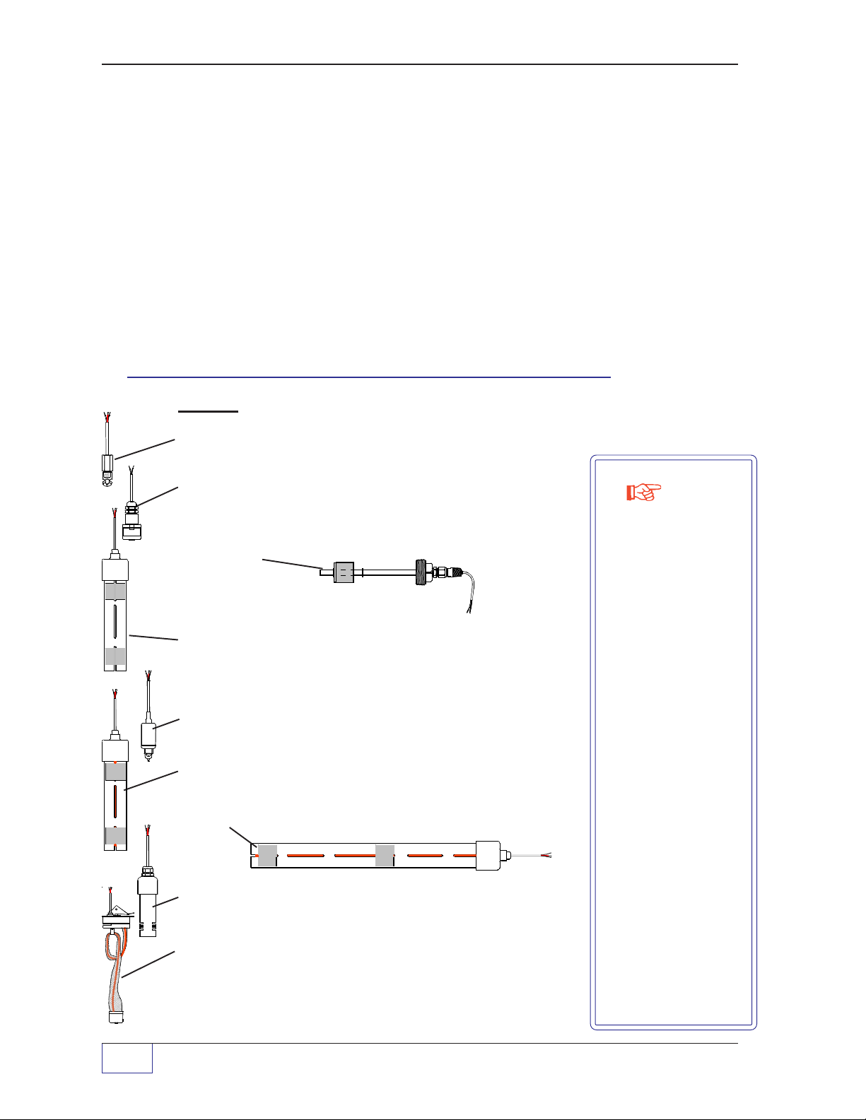
TSP-LL2 Probe Floats
BriteSensors® are
sensors that digitally
communicates the
sensor–type and
alarm status of the
sensor. Most
BriteSensors can
discriminate between
water and
hydrocarbon products
and produces
different alarm codes
for each.
Brite Sensors are
not approved for
use in European
Union markets
where ATEX
approved devices
are required.
Standard sensors
do not use digital
data. They operate
like an ON–OFF
switch which is closed
when no liquid is
present
and
open
when a liquid is
detected.
Floats for 4-inch (101.6 mm)riser pipes, order:
TSP-IGF4 for Gasoline, or TSP-IDF4 for Diesel and fuel oils.
Floats for 2-inch (50.8 mm)riser pipes, order:
TSP-IGF2 for Gasoline, or TSP-IDF2 for Diesel and fuel oils, or
TSP-SSP stainless steel float for Chemical products.
Manufacturers’ Tank Chart for each Tank
The manufactures’ Tank Chart and other documentation will be used for installation
and programming, and possibly, for future reference. Keep this information — do
not discard it!
TABLE 1-2: Approved Leak Detection Sensors
S
I
E
-
P
S
T
S
L
U
-
P
S
T
TSP-HIS
TSP- DDS
TSP-MWS
S
V
D
-
P
S
T
1 Page 1 - 10 TANK SENTINEL
Order:
See sensor manuals for materials required and installation details.
TSP-EIS (Electro-optical Interstitial liquid – Standard sensor)
TSP-ULS (Universal Liquid – Standard sensor)
TSP-HLS / (High product Level – Standard sensor)
TSP-HLST
H
T
S
L
P
-
S
TSP-HIS / (Hydrostatic Interstitial reservoir – BriteSensor)
TSP-HIS-XL
S
I
D
-
P
S
TSP-DIS (Discriminating Interstitial liquid – BriteSensor)
T
TSP-DDS (Discriminating Dispenser Sump – BriteSensor)
TSP-DTS (Discriminating Turbine Sump – BriteSensor)
TSP-DTS
TSP-DVS (Discriminating Vapor – BriteSensor)
TSP-MWS (Discriminating Monitoring Well – BriteSensor)
®
INSTALLATION GUIDE
NOTE

Installation Options:
RMC vs. Alternate – Direct Cable Burial Method
The requirement for, and cost of Rigid Metal Conduit (RMC), which is noted and
shown throughout this manual, can be reduced
installation method for liquid level probe and leak detection sensor cables. Follow
the instructions explicitly in the Direct Burial Cable Installation Guide (INCON
P/N: 000-1041).
Only use the type of cables specified in the Direct Burial Installation Guide for liquid
level probes and leak detection sensors, and Do Not exceed recommended cable
lengths. Also,
make sure local codes permit “direct burial” of cables.
IF
Installation Do’s and Don’ts – DO’s
DO Read the Installation Manual carefully before starting to install the Tank
Sentinel® system.
DO Plan and record all conduit runs to: junction boxes. Also record the types
(models) and locations of all accessories, and all sensors, before mounting
the Tank Sentinel® console.
you use the direct burial
DO Disconnect all power before making any electrical connections.
DO Install the Tank Sentinel® system to meet your National Electrical Code
(U.S.A. = NFPA 70), state and local electrical codes, and any applicable
safety codes, including U.S.A. – NFPA 30A.
DO Follow Intrinsically Safe (I.S.) wiring practices. All I.S. wiring must be
installed in sealed conduit. Intrinsically Safe probe, and all sensor wiring
must be separated from all other wiring.
DO Use the designated conduit “knockouts” to bring field wiring into the
console enclosure. Intrinsically safe probe, and all sensor wiring must be
isolated and run separately from all other wiring.
DO Install #12 AWG (2.0 mm) ground wires between the system safety ground
and a suitable earth ground, such as the ground bus in the electrical panel.
Smaller safety ground wiring is not acceptable.
INSTALLATION OVERVIEW Page 1 - 11 1

DO Provide a dedicated 10 Amp circuit breaker, which is marked exclusively for
“Tank Sentinel System power ONLY”.
DO Make sure conduits and junction boxes are dry and watertight. Faulty
operation will result from wet wiring.
DO Mount the Tank Sentinel console in a dry indoor environment, where it will
be protected from extremes in temperature.
DO Block off your work area when working around the tanks if vehicles can
approach the area.
Installation Do’s and Don’ts – DON’Ts
DON’T Mount the Tank Sentinel® console in a hazardous area where flammable
liquid vapors may be present. An explosion could result.
DON’T Allow field service work by unauthorized persons. Field service by
unauthorized personnel can render the system unsafe and will void the
warranty.
DON’T Operate the system without safety shields installed.
DON’T Exceed the maximum probe cable length recommendations. Unreliable
operation and erroneous readings could result.
DON’T Wire the probes with unapproved types of cable. Unreliable operation,
safety hazards, and erroneous readings will result.
DON’T Short circuit the probes or wire them backwards. The I.S. circuits may be
damaged.
DON’T Mix or run any non-intrinsically-safe wiring in conduit/pull box / wireway that
contains Intrinsically Safe (I.S.) probe or sensor wiring. Intrinsically Safe
liquid-level probe wiring, and leak-detection sensor wiring, must be
isolated from all other wiring.
DON’T Mix or run any wiring in conduit/raceways that contain INCON Tank
Sentinel® wiring.
1 Page 1 - 12 TANK SENTINEL
®
INSTALLATION GUIDE
DON’T Substitute any components. Intrinsic safety could be impaired.
DON’T Drill or punch any holes in the Tank Sentinel console enclosure.
CAUTION
Read the installation instructions carefully. The Tank Sentinel
®
system is designed to be safe when correctly installed. It is possible to create
explosion hazards, health hazards, risk of death, and environmental hazards
through incorrect installation.
Installation Procedure Overview – Steps
Step 1 Excavate down to the tanks to gain access to the bungs (openings) which will be
used to install the level probes, and interstitial leak detection sensors (USTs only).
Step 2 Install a 4 inch (101.6 mm) riser pipe on each tank for the level probe. This riser
must allow access into the tank. (Note: For tanks with a 2 inch (50.8 mm)bung
access, add a 4-to-2 inch (101.6 to 50.8 mm) reducer at the tank and then install a
4 inch (101.6 mm) riser. This configuration requires 2 inch (50.8 mm) floats — see
instructions provided).
Step 3 Install a 2 or 4 inch (50.8 or 101.6 mm) riser pipe (as required) on each tank for
each optional interstitial leak detection sensor. This riser must allow access to the
interstitial space between double wall tanks.
Step 4 Install a manhole around each riser (USTs only).
Step 5 Mount the Tank Sentinel console in a suitable indoor location.
Step 6 Install threaded, conduit between the manhole junction boxes, I.S. pull boxes, and
the console. Install EYS seal fittings before the pull boxes, and manhole junction
boxes (manholes apply to USTs only)
Step 7 With power off: Install the probe and sensor wiring to the Tank Sentinel console.
Use ONLY the cables and wire types specified in this manual (or the Direct Burial
Cable manual).
INSTALLATION OVERVIEW Page 1 - 13 1

Step 8 With power off: Install conduit and connect the line power to the console. Leave
the line power Circuit Breaker off at the electrical power panel until all wiring has
been verified correct.
Step 9 Install a separate telephone line for the optional modem / fax.
Step 10 With power off: Install optional accessories, conduit, and wiring to external
devices, such as discrete/run inputs or line leak detectors, as detailed in this
manual or in an installation addendum.
Step 11 With power off: Install optional conduits and wire external alarm devices, such as
a TS-RK (remote Alarm Acknowledge unit) and TS-RA1 or TS-RA2 (remote Tank
Overfill Alarm unit) as described in their Installation manual.
Step 12 Review and verify that all level probe wiring is completed in accordance with this
manual, and that all other devices (Sensors, External Devices, and Alarm units,
etc.) are wired correctly. Incorrect liquid-level probe wiring, or leak-detection sensor
wiring, will damage the console at start-up.
Step 13 Reinstall all terminal safety shields/covers. Power up and program the Tank
Sentinel
®
system for your application, as described in the Programming Guide.
Step 14 Test and then install each of the level probes in their tanks.
Step 15 Test and then install the leak detection sensors between the walls of the double
wall tanks, in liquid sumps, or other locations as described in their installation
manual ...an installation manual is provided with each type of sensor.
Step 16 Seal all tested probe and sensor EYS conduit fittings with epoxy and then reinstall
all junction box cover gaskets and covers.
—
❖
—
1 Page 1 - 14 TANK SENTINEL
®
INSTALLATION GUIDE
2 Riser Pipes & Manholes
Product Codes:
none = all products
T1
= TS-1001, T2 = TS-2001, T4 = TS-504, T7 = TS-750, T8 = TS-508,
CAUTION
National Electrical Code when installing the Tank Sentinel
CAUTION
during installation if the tank site is located where vehicular traffic is possible.
You must comply with state and local electrical codes as well as the
Take precautions to insure that vehicles cannot enter the work area
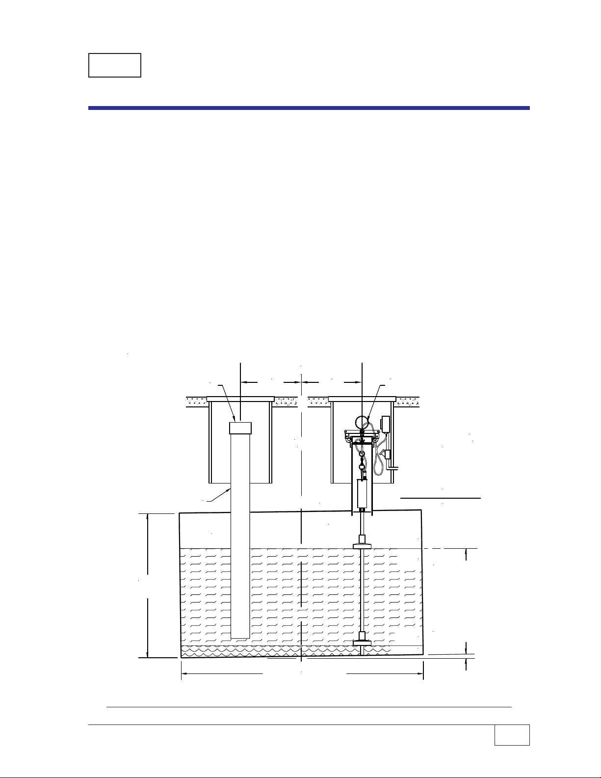
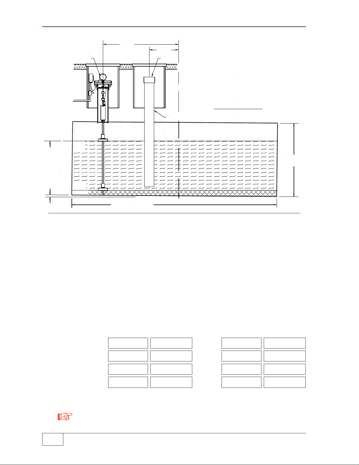
Riser Pipes for Level Probes
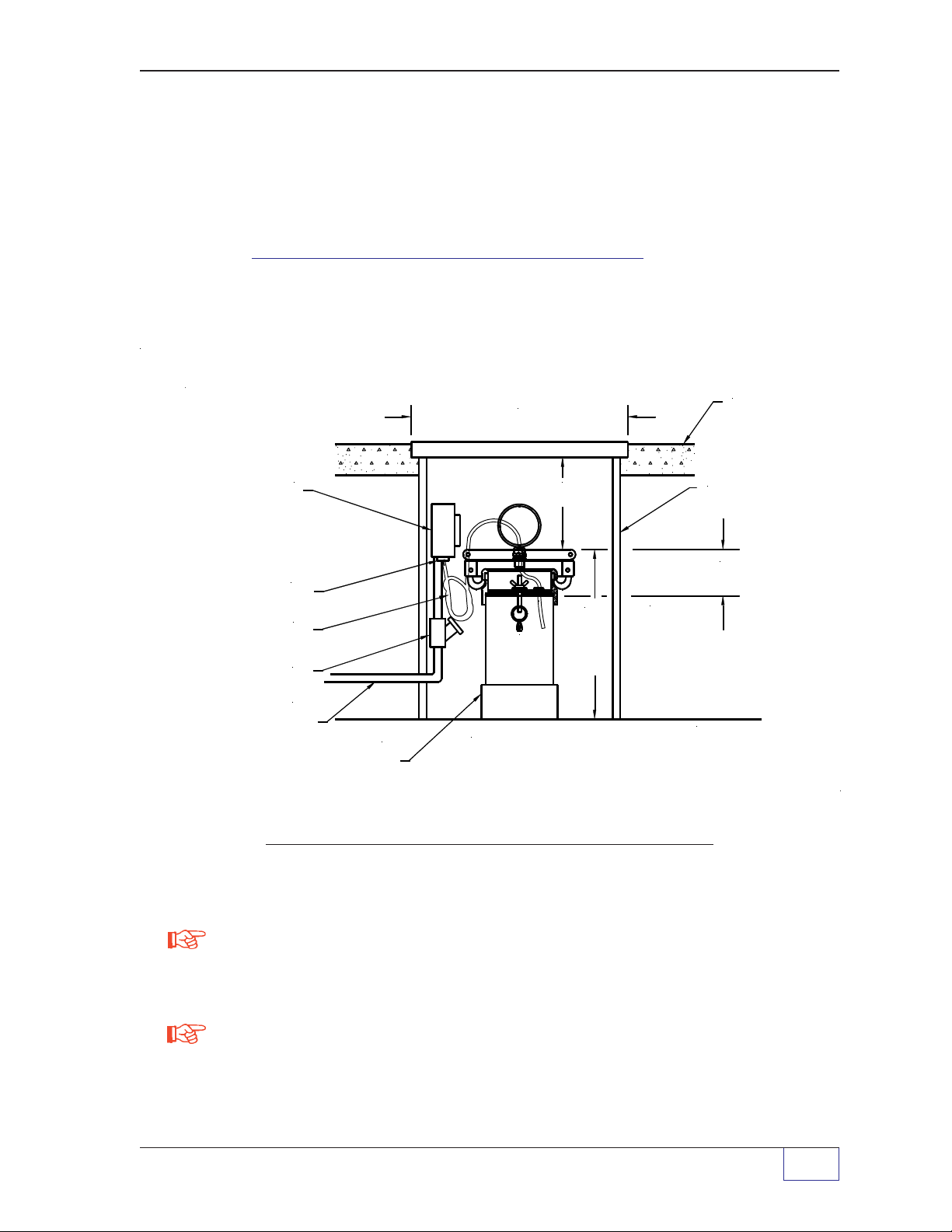
The riser pipe and manhole installation for the level probe is shown in Figure 2-1. If
you are installing the Tank Sentinel probe in an existing tank, which is buried, you
must excavate down to the top of the tank. The Tank Sentinel liquid level probe
must be installed in a four inch riser pipe. Riser pipes should be made of 4 inch,
threaded, ANSI schedule 40 pipe, with 4-8 NPT (DN115 BSP 4-11) male threads at
both ends. This method of installation makes it possible to access the level probe
for service or replacement if necessary.
®
system.
The probe shaft must extend into the riser pipe at least 5 inches (127 mm) to avoid
submerging the head of the probe if a tank is overfilled.
NOTE
Information Required
If possible, the level probe should be installed at or near the center of the tank. This
will provide the most accurate volume readings.
For each tank installed, you will need the tank manufacturers’ documentation to find
the: Tank Model Number, Tank Size, Bung Access Location and Sizes, and the
Tank Strapping Table or “Tank Chart”. This data will also be used when the Tank
Sentinel® system is setup / programmed — Do Not discard this information.
The length of the riser pipe installed will depend on the tank diameter, probe length
and depth at which the tank is buried. From these dimensions, it is possible to
determine a minimum and maximum riser length. The maximum tank diameter and
the overall length of standard Tank Sentinel probes are listed in Table 2-1.
RISER PIPES & MANHOLES Page 2 - 1 2
TABLE 2-1. STANDARD (STD) TANK SENTINEL PROBES
dimensions are listed in inches (mm)
Probe Probe Maximum Model TSP-LL2
Model Shaft Tank Probe
Length Diameter Overall Length
LL2-29 29(737) 24(610) 39(991)
LL2-41 41(1041) 36(914) 51(1295)
LL2-53 53(1346) 48(1219) 63(1600)
LL2-69 69(1753) 64(1626) 79(2007)
LL2-77 77(1956) 72(1829) 87(2210)
LL2-81 81(2057) 76(1930) 91(2311)
LL2-89 89(2261) 84(2134) 99(2515)
LL2-101 101(2565) 96(2438) 111(2819)
LL2-113 113(2870) 108(2743) 123(3124)
LL2-125 125(3175) 120(3048) 135(3429)
LL2-131 131(3327) 126(3200) 141(3581)
LL2-137 137(3480) 132(3353) 147(3734)
LL2-149 149(3785) 144(3658) 159(4039)
Riser Pipe Length Calculations
Minimum Riser Length
Start with the overall length of the probe, add 5 inches (127mm) for the support
chain, and subtract the tank diameter. See Example minimum riser length
calculations (below) for a TSP-LL2-101 probe in two different sized tanks.
92 Inch (2337mm)Tank 96 Inch(2438mm) Tank
inches (mm) inches (mm)
TSP-LL2-101 Probe Overall Length 111(2819) 111(2819)
Allowance for suspension chain + 5(127) + 5(127)
Total 116(2946) 116(2946)
Tank diameter – 92(2337) – 96(2438)
Minimum Riser Length = 24(609) 20(508)
NOTE
It is possible through the minimum riser length equation for the calculation to be
less than 18 inches. It is recommended that the riser be at least 18 inches (457
mm) for a model TSP-LL2 Probe (Reference Figure 2-1).
2 Page 2 - 2 TANK SENTINEL
®
INSTALLATION GUIDE
Maximum Riser Length
Take the distance from grade level to the top of the tank, and then subtract 6
inches (152.4 mm) — which is the minimum riser top to grade distance. See the
Example maximum riser length calculation (below):
Grade to top of tank 36" (914.4 mm)
Minimum riser to grade – 6" (152.4 mm)
Maximum Riser Length = 30" (762 mm)
WEATHERPROOF
JUNCTION BOX
COMPRESSION
GLAND FITTING
EXCESS CABLE
"COILED-UP"
EYS SEAL FITTING
1/2" (12.7 mm)
OR 3/4" (19.1 mm)
CONDUIT
ISOLATION BUSHING
(MAY B E R E Q UIRED
WITH STEEL TANK)
14 INCH (356 mm) MINIMUM
DIAMETER MANHOLE COVER
6.0" TO 18"
152 mm TO 457 mm
18.0"
(457 mm)
4.0" RISER PIPE
ANSI SCH 40
or
DN115
BSP 4-11
NOTE:
INCREASE THE 18" (457 mm) MINIMUM DIMENSION
IF THE PROBE LENGTH IS OVER-LENGTH FOR
THE TANK. ALSO SEE SECTIONS 3, 5, & 6.
MIN.
SEE
NOTE
BELOW
FILL
MATERIAL
CONCRETE SLAB
(TYPICAL)
PER NFPA30
(GRADE LEVEL)
MANHOLE
2.75 REF.
(69.8 mm)
TOP OF TA NK
NOTE
Hint
Figure 2-1. Typical Level Probe – Riser Pipe & Manhole
A problem exists if the maximum riser length is less than the minimum calculated
riser length. This may be the result of an incorrect calculation, an inappropriate
choice of probe for the tank diameter, or insufficient burial depth.
It is recommended that the top of the riser be no more that 18 inches (457 mm)
maximum below grade level to provide easy access for service.
RISER PIPES & MANHOLES Page 2 - 3 2
Riser Installation — Level Probe
After excavating down to the top of the tank, locate the bung that will be used to
install the riser pipe and level probe. Apply thread sealant to the “tank-side” of the
threaded riser pipe, remove the pipe plug from the tank bung, and install the 4 inch
(102 mm) riser pipe in this bung.
NOTE
For tanks with 2 inch (50.8 mm) bungs, add a 4-to-2 inch (101.6 to 50.8 mm)
reducer at the tank and then install a 4 inch riser (this configuration requires 2-inch
floats). For tanks with 3 inch (76.2 mm) bungs, add a 4-to-3 inch (101.6 to 76.2
mm) reducer at the tank and then install a 4 inch (101.6 mm) riser (this
configuration also requires 2-inch (50.8 mm) floats).
CAUTION
When installing a riser pipe in a steel tank, applicable codes of
practice may require that a nonconductive isolation bushing be installed between
the tank and riser pipe. It is the installer’s responsibility to comply with all applicable
federal, state and local codes.
Manhole Installation
Install an approved manhole at each riser pipe location. Manholes of 14" (355.6
mm) minimum diameter are recommended. To make sure that there is adequate
clearance for the installation of the electrical junction box and for service, position
the manhole over the riser carefully — offset the manhole around the riser pipe. It is
recommended that the bottom of the manhole be filled with crushed stone to
facilitate drainage. Do not cover the top of the riser with fill material, it must remain
accessible for service, and for probe installation. (Manholes are not required with
AST applications.)
—
2 Page 2 - 4 TANK SENTINEL
❖
—
®
INSTALLATION GUIDE
3 Tank Measurement s
Product Codes:
T1
= TS-1001, T2 = TS-2001, T4 = TS-504, T7 = TS-750, T8 = TS-508,
none = all products
Before Backfilling
In order to achieve the highest possible accuracy from the Tank Sentinel system, a
number of tank measurements must be made before the tank excavation is
backfilled. This data is used to calculate the tank tilt offset for tanks that are not
level. The best method uses calculated product and water offsets that virtually
“moves” the probe to the center of the tank. If the probe is mounted in the center of
the tank, then no corrections are required (offsets = 0.0). Alternatively, if the data
to calculate tank tilt is not known, or if the tank is not seriously tilted, then use +/–
offsets to adjust the probe readings to match the stick readings at fill.
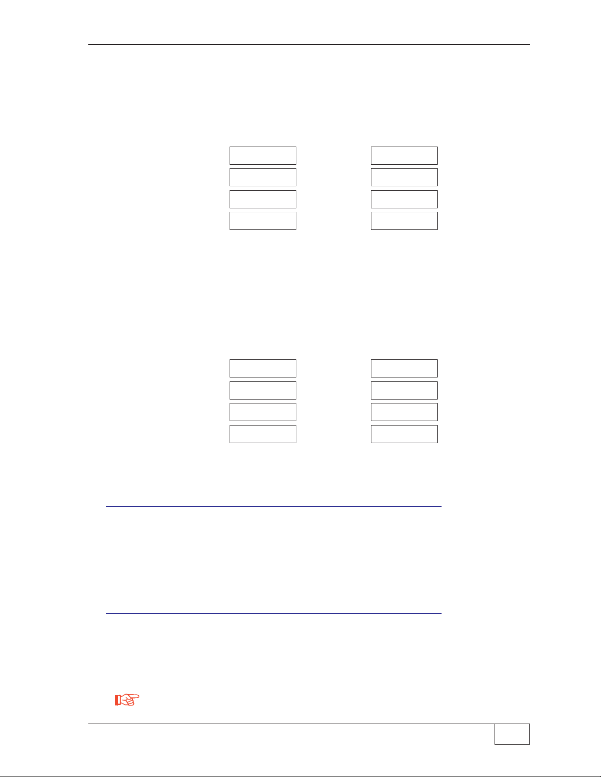
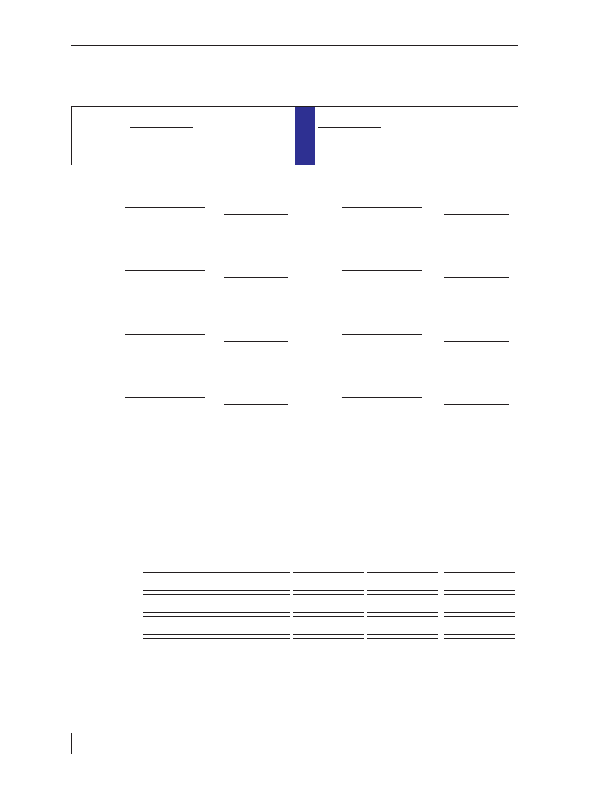
Figure 3 - 1 shows the tank tilt formula to use when the fill tube and probe are on
opposite sides of the tank center-line. Figure 3 - 2 shows the formula to use when
the fill tube and probe are on the same side of the tank center-line.
Fill
CENTER OF TANK
" XF " " XP "
level
Probe
DROP TUBE
TANK
DIAMETER
" LF "
Level
at Fill
C
L
TOP OF TANK
" LP "
Level
at Probe
LENGTH OF TANK
Fill & P r o be on
opposite sides of
Tank
Center...
Product / Water
Offs e t =
(LF - L P ) * X P
XP + XF
AIR
FUEL
FUEL
WATER
PRODUCT
LEVEL
Tank shown
tilted
C
L
Figure 3-1. Typical Tank – Fill & Probe on Opposite Sides of Tank Center
TANK MEASUREMENTS Page 3 - 1 3
level
Probe
CENTER OF TANK
" XP "
" XF "
Fill
Fill & Probe on
the same side of
the tank
C
L
" LF "
Level
at Fill
DROP TUBE
PRODUCT
LEVEL
Tank
shown
tilted
TOP OF TANK
" LP "
AIR
FUEL
FUEL
WATER
Level
at Probe
LENGTH OF TANK
Figure 3-2. Typical Tank – Fill & Probe on the Same Side of the Tank Center
Product Level Measurement – values
You must measure the product level at two points in the tank to determine the
degree to which it is tilted. A level measurement is made at the fill pipe (drop tube)
and at the location where the level probe will be installed. Record these level
measurements for each tank in the spaces provided below.
Product / Water
Offset =
(LF - LP) * XP
XP - XF
TANK
DIAMETER
The tank must have liquid in it before these measurements are taken. If a tank is
empty, collect all of the other data until the tank has been at least partially filled,
and then take these level measurements.
Level at: FILL (LF) PROBE (LP) FILL (LF) PROBE (LP)
TANK 1
TANK 3 TANK 4
TANK 5 TANK 6
TANK 7 TANK 8
NOTE
The blank fields for tanks 5 though 8 are for Tank Sentinel
numbers: TS-2001 and TS-508 only (this is true throughout this manual).
3 Page 3 - 2 TANK SENTINEL
®
TANK 2
®
consoles, Model
INSTALLATION GUIDE
Distance from Fill to Center-line – “ XF ” values
Carefully measure the distance between the center of the Fill tube and the center of
the tank. We call this distance “ XF.” Record the distance between these two
points for each tank in the spaces provided below.
“ XF ” “ XF ”
TANK 1 TANK 2
TANK 3 TANK 4
TANK 5 TANK 6
TANK 7 TANK 8
Distance from Probe to Center-line – “ XP ” values
Carefully measure the distance between the center of the opening where the level
probe will be installed and the center of the tank. We call this distance “ XP.”
Record the distance between these two points for each tank in the spaces provided
below.
TANK 1 TANK 2
TANK 3 TANK 4
TANK 5 TANK 6
TANK 7 TANK 8
Calculating Tank Tilt
Water Offset
Stick the tank to ensure that there is no water present. The water offset in the ATG
setup programming can be used to “zero” the water level reading of the ATG.
Typically, a small negative number in the water offset is needed to zero the water
float ...be sure to program the gradient before figuring out the water offset.
Product Offset
See next page. Fill in the blank equations with the appropriate & correct values for
each tank. Perform the mathematical operations indicated in the formula used to
calculate the tank tilt offset for every tank. Write the answers in the blank spaces.
“ XP ” “ XP ”
NOTE
Avoid errors... use a calculator and double-check all calculations. Keep all positive
and negative (+/– sign) values... offsets can be either positive or negative.
TANK MEASUREMENTS Page 3 - 3 3
Reference Figures 3 - 1 and 3 - 2. Use the appropriate Formula below, to find the
Tilt value for each Tank (the sign of XF changes depending on which figure is
used)... N represents a Tank number, and an asterisk (
) means multiply by:
*
Tilt N =
(LF – LP)
XP + XF XP – XF
(
PROBE AND FILL ON OPPOSITE SIDES OF TANK CENTER
XP (LF – LP)* XP
*
per Figure 3 - 1 per Figure 3 - 2
or
) (
PROBE AND FILL ON SAME SIDE OF TANK CENTER
() ()
Tilt 1 =
= Tilt 2 = =
() ()
() ()
Tilt 3 = = Tilt 4 = =
() ()
() ()
Tilt 5 = = Tilt 6 = =
() ()
() ()
Tilt 7 = = Tilt 8 = =
() ()
)
Tank Type, Cap acity, Inside Diameter, and Length Data
Record this data for each tank in the spaces provided below. If the inside diameter or
length of the tank is not known, measure it carefully.
TYPE CAPACITY DIAMETER LENGTH
TANK 1
TANK 2
TANK 3
TANK 4
TANK 5
TANK 6
TANK 7
TANK 8
3 Page 3 - 4 TANK SENTINEL
—
❖
—
®
INSTALLATION GUIDE
4 Console Mounting
Product Codes:
T1
= TS-1001, T2 = TS-2001, T4 = TS-504, T7 = TS-750, T8 = TS-508,
none = all products
Console Location
To get maximum benefit from the system, locate the console where personnel
can easily make use of it — mount it at eye-level for operator convenience. The
selected location must be indoors, and in an area that is classified as
nonhazardous. The console must be well protected from rain, condensation,
extremes of temperature, severe vibration, and other conditions which could
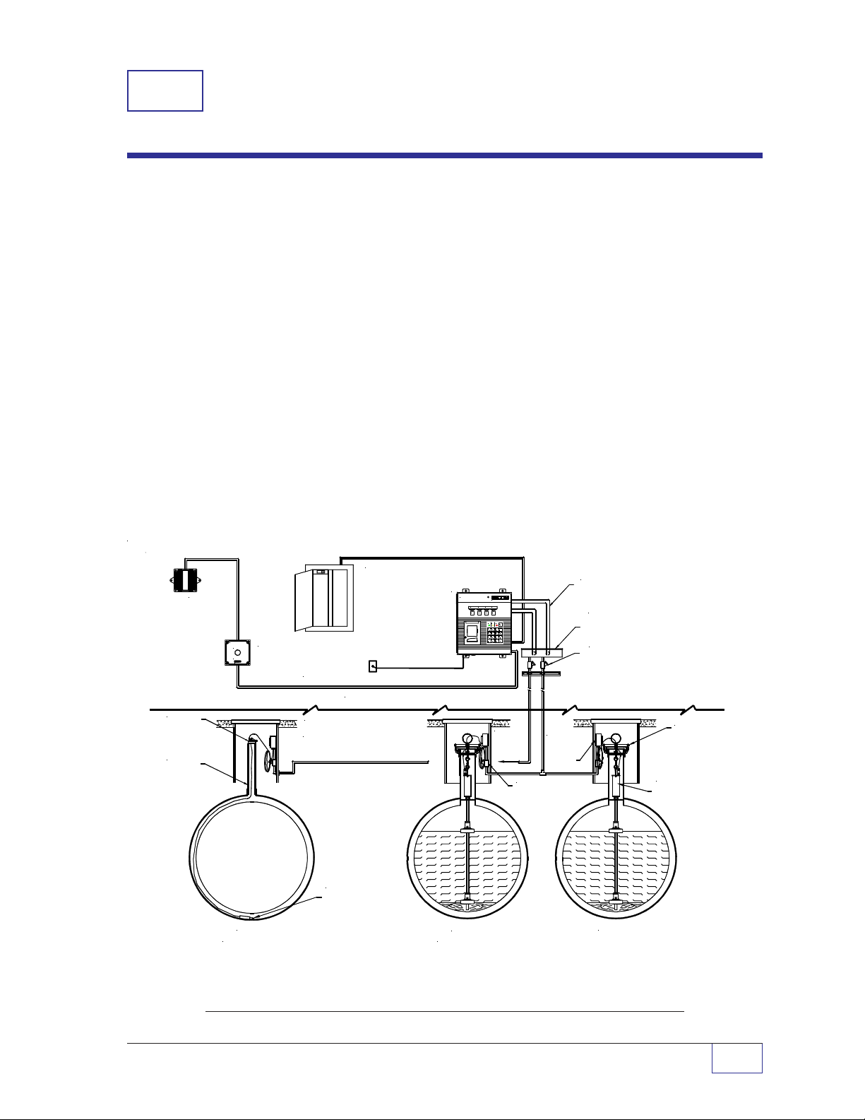
cause damage. A typical UST system installation is shown in Figure 4-1.
Mount the console level on a vertical surface using appropriate fasteners
between 2 feet (0.6 m) and 6 feet (1.9 m) high. For European applications the
console must be located in a pollution degree 2 environment per IEC60664.
In addition, the console must be located so that the wiring, between the level
probes, and the console DOES NOT exceed 1500 feet (457.2 m). See
CAUTION and WARNING on the next page.
MODEL TS-RA2
REMOTE O V ER F ILL
ALARM UNIT
MODEL
TSP-KI2
RISER CAP
RISER
PIPE
TANK OVERFILL ALARM
ACKNOWLEDGE
MODEL TS-RK
ACKNOWL E D G E
MODEL TS-RK
INTELLIGENT CONTROLS INC.
74 INDUTRIAL PARK ROAD
SACO, MAINE 04072
UNIT
TANK 1
(SECTION A)
ELECTRICAL POWER PANEL
T2 / T1 / T4
T7 / T8 TANK
SENTINEL
CONSOLE
(MOD EL
T1 SHOWN)
TELEPHONE LINE FOR OPTIONAL FAX/MODEM
NON-HAZARDOUS AREA
HAZARDOUS AREA
(CLASS I, DIVISION 1,
GROUP D)
LEAK DETECTION
SENSOR
MODEL TSP-DIS
OR
TSP-EIS
(TS-2001 / TS-1001
CONSOLES ONLY)
TS-1001 TANK SENTINEL
STATUS
SYSTEM
OKAY
M 1
M 2
FEED
TANK 1...
(SECTION B)
R
TANK
OKAY
M 3
POWER WARNINGS ALARM
A
N B
PRODUCT
1
D
Q E5R F
TANK
4
H
U
7
ACK
SHIFT
ENVIRONMENTAL CONTRO LS DIVIS ION
SENSOR
OKAY
M 4
P
O C
GROSS
LEVEL
2
3
S
WATER
ULLAGE
6
W
I
V
J
REPORTZMENU
ALARM
9
L8Y M
TEST 0SETUP.ENTER
TO
TSP-DIS
OR
TSP-EIS
ALARM
TEST
CANCEL
CANCEL
G
T
UP
+/-
K X
DOWN
SPACE
EYS SEAL FITTING
(TYPICAL)
CONDUIT FOR
INTRINSICALLY SAFE
PROBES & SENSORS
SEPARATE WEATHERPROOF
PULL BOX FOR INTRINSICALLY
SAFE PROBE AND SENS O R
CABLES ONLY
EYS SEAL FITTING
(TYPICAL)
WEATHERPROOF
JUNCTION
BOX
...TANK 4
MODEL
TSP-K4A
RISER CAP
MODEL TSP-LL2
LIQUID LEVEL
PROBE
Figure 4-1. Typical Tank Sentinel UST Installation
CONSOLE MOUNTING Page 4 - 1 4
WARNING
Do not install the console in a location where flammable vapors
may be present. An explosion could result causing serious injury, property loss,
or death.
CAUTION
The maximum distance from the Tank Sentinel console to the
liquid level probe must not exceed 1500 feet (457.2 m) for model TSP-LL2
probes. In addition, the maximum distance from the Tank Sentinel
leak detection sensors must not exceed 1500 feet (457.2 m). Improper system
operation, system error alarms, and inaccurate data can result if level probe
cable lengths or leak detection sensor wiring exceed these limits. Reference
Sensor Installation manual(s) for TS-1001 consoles, Materials Required and
Level Probe Wiring in Chapter 1 & 7 of this manual.
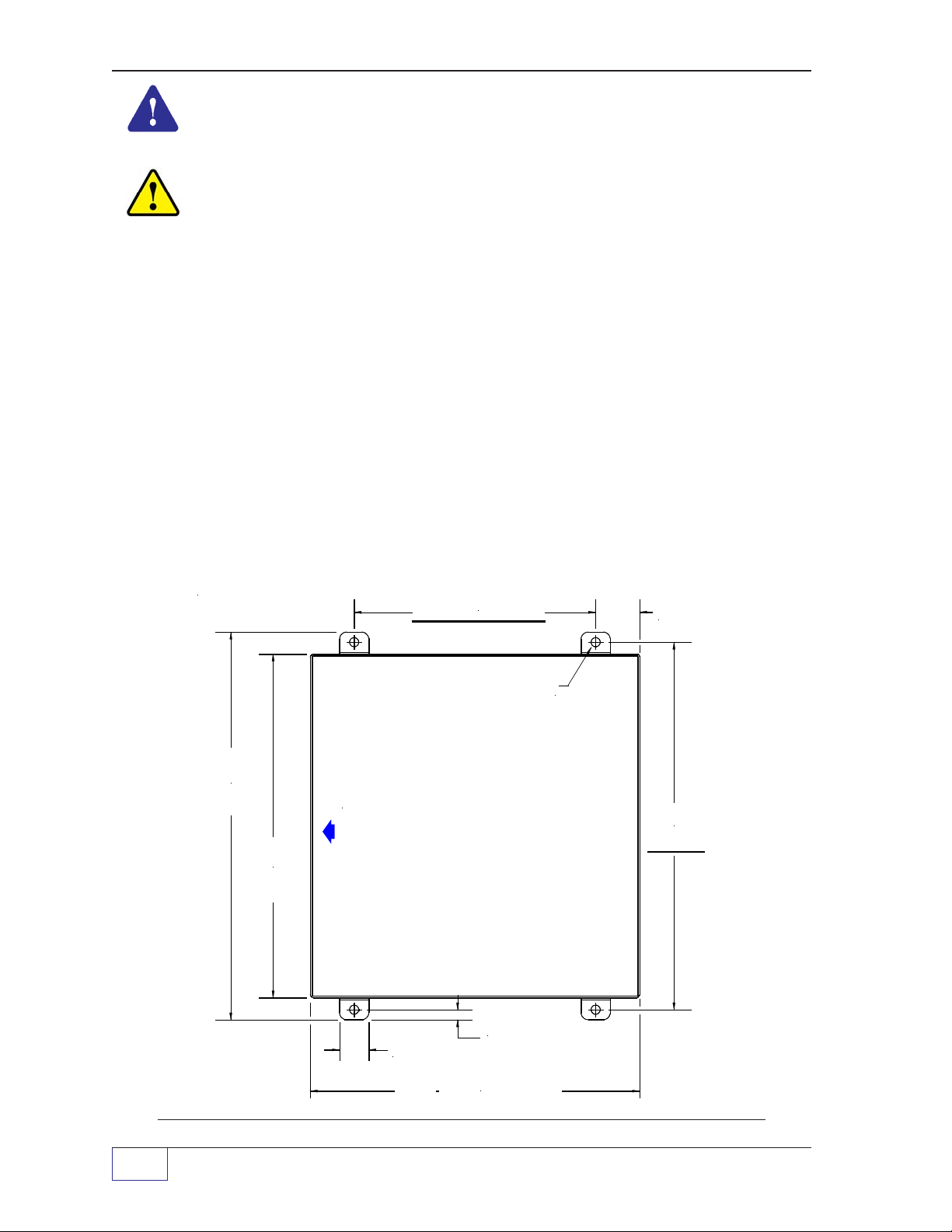
Mounting the Console
Use the holes in the four right angle brackets to mount the Tank Sentinel
console enclosure. The location of the four holes is shown in Figures 4-2 & 4-3
Select fasteners that have sufficient load carrying capacity and which are
appropriate for the wall construction. Mount the Tank Sentinel
vertically and level on an interior wall. Also, locate the console so the console
door can open fully (it is hinged on the left side).
7.00 (177.8 mm)
®
console
1.50
(38.1 m m)
TYP.
®
console to
®
13.38
(339.9
mm)
REF
11.75
(298.5
mm)
REF
HINGE SIDE of
CONSOLE DOOR
11.00 x 12.00
(279.4 x 3 0 4.8 mm )
REF
1.00
(25.4 mm)
TYP.
THRU MOUNTING HOLES
10.75 (273.1 mm) REF
0.31 (7.9 mm)
TYP. FOUR PLACES
0.31
(7.9 mm )
TYP.
12.75
(323.9
mm)
Figure 4-2 T1 / T8 / T4 / T7 Console Mounting Holes (door not dimensioned)
4 Page 4 - 2 TANK SENTINEL
®
INSTALLATION GUIDE
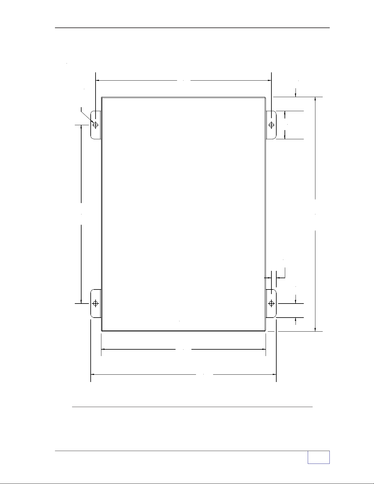
12.56"
(319 mm)
(4 TYP)
THRU HOLES
0.31" (7.9 mm)
1.00"
(25.4 mm)
2.00"
(50.8 mm)
12.75"
(323.9 mm)
0.35"
(8.9 mm)
1.00"
(25.4 mm)
HINGE SIDE
CONSOLE DOOR
(17.00" x 12.00" REF)
(431.8 mm x 3 0 4.8 mm)
11.75" REF
(298.5 mm)
13.25"
(336.6 mm)
(425.5 mm)
16.75" REF
Figure 4-3 T2 Console Mounting Holes (door not dimensioned)
—
CONSOLE MOUNTING Page 4 - 3 4
❖
—
 Loading...