

FRANKE FSW908TCBKXS, FSW908TCWHXS User Manual

Istruzioni per l’uso e l’installazione
Cappa
Instructions for use and installation
Cooker Hood
Mode d’emploi et installation
Hotte de Cuisine
Bedienungsanleitung und Einrichtung
Dunstabzugshaube
Kullan
ım ve montaj talimatları
Davlumbaz
Betjenings
-
og installationsvejledning
Emhætte
Uživatelská P
øíruèka
Kapuce
FSW 908 TC
IT
GB
FR
DE
TR
DK
CZ

2
2
INDICE
CONSIGLI E SUGGERIMENTI ..............................................................................................................................................4
CARATTERISTICHE..............................................................................................................................................................5
INSTALLAZIONE....................................................................................................................................................................7
USO......................................................................................................................................................................................10
MANUTENZIONE.................................................................................................................................................................11
INDEX
RECOMMENDATIONS AND SUGGESTIONS....................................................................................................................14
CHARACTERISTICS............................................................................................................................................................15
INSTALLATION ....................................................................................................................................................................17
USE.......................................................................................................................................................................................20
MAINTENANCE....................................................................................................................................................................21
SOMMAIRE
CONSEILS ET SUGGESTIONS ..........................................................................................................................................24
CARACTERISTIQUES.........................................................................................................................................................25
INSTALLATION ....................................................................................................................................................................27
UTILISATION........................................................................................................................................................................30
ENTRETIEN..........................................................................................................................................................................31
INHALTSVERZEICHNIS
EMPFEHLUNGEN UND HINWEISE....................................................................................................................................34
CHARAKTERISTIKEN..........................................................................................................................................................35
MONTAGE............................................................................................................................................................................37
BEDIENUNG.........................................................................................................................................................................40
WARTUNG............................................................................................................................................................................41
IÇERIKLER
TAVSIYELER VE ÖNERILER ..............................................................................................................................................44
ÖZELLIKLER........................................................................................................................................................................45
MONTAJ...............................................................................................................................................................................47
KULLANIM............................................................................................................................................................................50
BAKIM...................................................................................................................................................................................51
INDHOLD
RÅD OG ANVISNINGER......................................................................................................................................................54
APPARATBESKRIVELSE....................................................................................................................................................55
INSTALLATION ....................................................................................................................................................................57
BRUG....................................................................................................................................................................................60
VEDLIGEHOLDELSE...........................................................................................................................................................61
IT
EN FR DE TR DK

3
3
OBSAH
RADY A DOPORUČENÍ.......................................................................................................................................................64
HLAVNÍ PARAMETRY .........................................................................................................................................................65
INSTALACE..........................................................................................................................................................................67
POUŽITÍ................................................................................................................................................................................70
ÚDRŽBA...............................................................................................................................................................................71
CZ
IT
4
4
CONSIGLI E SUGGERIMENTI
Questo libretto di istruzioni per l'uso è previsto per più versioni dell' appare
c
chio.
É possibile che siano descritti singoli particolari della dotazione, che non riguardano il Vostr o apparec c hio.
INSTALLAZIONE
• Il produttore declina qualsiasi responsabilità per danni dovuti ad installazione non
corretta o non c onfor me alle regole d ell’art e.
• La distanza minima di sicurezza tra il Piano di cottura e la Cappa deve essere di
650 mm, (alcuni modelli possono es ser e installati ad un’alt ezza inferiore, fare riferimento ai paragraf i ingo mbro e i ns tal laz ione) .
• Verificare che la tensione di rete corrisponda a quella riportata nella targhetta
posta all’interno della Cappa.
• Per Apparecchi in Classe I
a
accertar si che l’impian to ele ttrico do mestico g aran ti-
sca un corr etto sc ar ic o a ter ra.
• Collegare la Cappa all’uscita dell’aria aspirata con tubazione di diametro pari o
superiore a 120 mm. Il percorso della tubazione deve essere il più breve possibile.
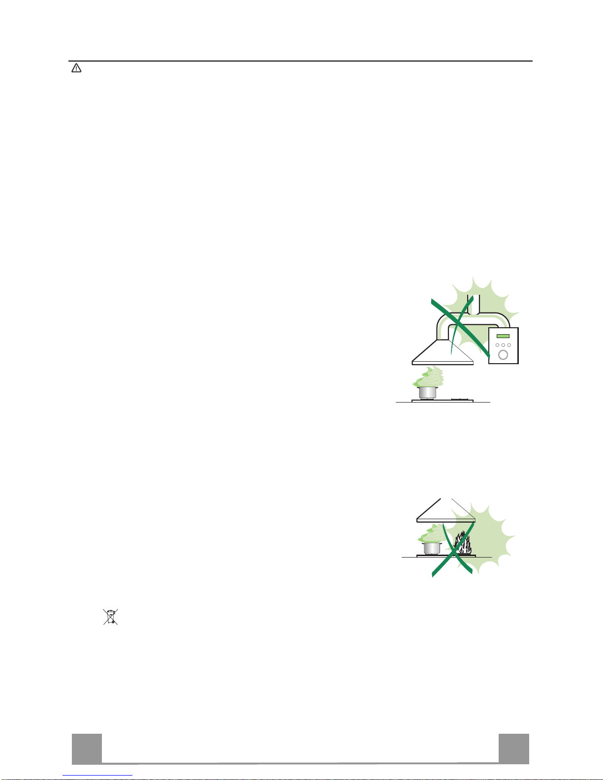
• Non collegare la Cappa a condotti di scarico dei fumi prodotti da combustione
(caldaie, c aminet t i, ec c.) .
• Nel caso in cui nella stanza vengano utilizzati sia la Cappa che apparecchi non
azionati da energia elettrica (ad esempio apparecchi utilizzatori di gas), si deve
provvedere ad una aerazione sufficiente dell’ambiente. Se la cucina ne fosse
sprovvista, praticare un’apertura che comunichi con l’esterno, per garantire il richiamo d’aria puli ta.
USO
• La Cappa è stata progettata esclusivamente per uso domestico, per abbattere gli
odori della cuc ina.
• Non fare mai uso impropr io del la Cap pa.
• Non lasciare fiamme li bere a f ort e int ens it à sott o la Cappa i n funz ione.
• Regolare sempre le fiamme in modo da evitare una evidente fuoriuscita laterale
delle stess e ri spet t o al fondo del le p ent ole.
• Controllare le fri ggit ric i durant e l’ uso: l’ oli o surri sc aldat o potr ebb e inf iammar si .
• Non preparare aliment i f lambè s ot to l a cappa da c uc ina; peri c olo d'i ncen di o.
• Questo apparecchio non deve essere u tilizzato da perso ne (bamb ini inclu si) con
ridotte capacità psichiche, sensoriali o mentali, oppure da persone senza esperienza e conoscenza, a meno che non siano controllati o istruiti all’uso
dell’apparecchio da per son e r esponsabili della loro sicurezza.
• I bambini devono essere supervisionati per assicurarsi che non giochino con
l’apparecchi o.
MANUTENZIONE
• Prima di procedere a qualsiasi operazione di manutenzione, disinserire la Cappa
togliendo la spina elettrica o spegnendo l’interruttore generale.
• Effettuare una scrupolosa e tempestiva manutenzione dei Filtri secondo gli intervalli consigliati (Rischio di incendio).
• Per la pulizia d e lle su pe rfici d e lla Ca pp a è suffi cie n te u tiliz za re u n pann o umido e
detersivo l iqui do neutr o.
Il simbolo sul prodotto o sulla confezione indica che il prodotto non deve essere considerato
come un no r m ale rifi uto domestico, m a deve essere portato n el punto di r ac colta a ppropri at o per
il rici cl aggi o di a ppar ecc hi at ur e el et tric he e d el ettr o nic he. P rov v edendo a smaltire questo prodotto in modo appropriato, si contribuisce a evitare potenziali conseguenze negative per l’ambiente
e per la salute, che potrebbero derivare da uno smaltimento inadeguato del prodotto. Per informazioni più dettagliate sul riciclaggio di questo prodotto, contattare l’ufficio comunale, il servizio
locale di smaltimento rif iut i o il negozio in cui è stato acqu istat o il prodot to .
IT
5
5
CARATTERISTICHE
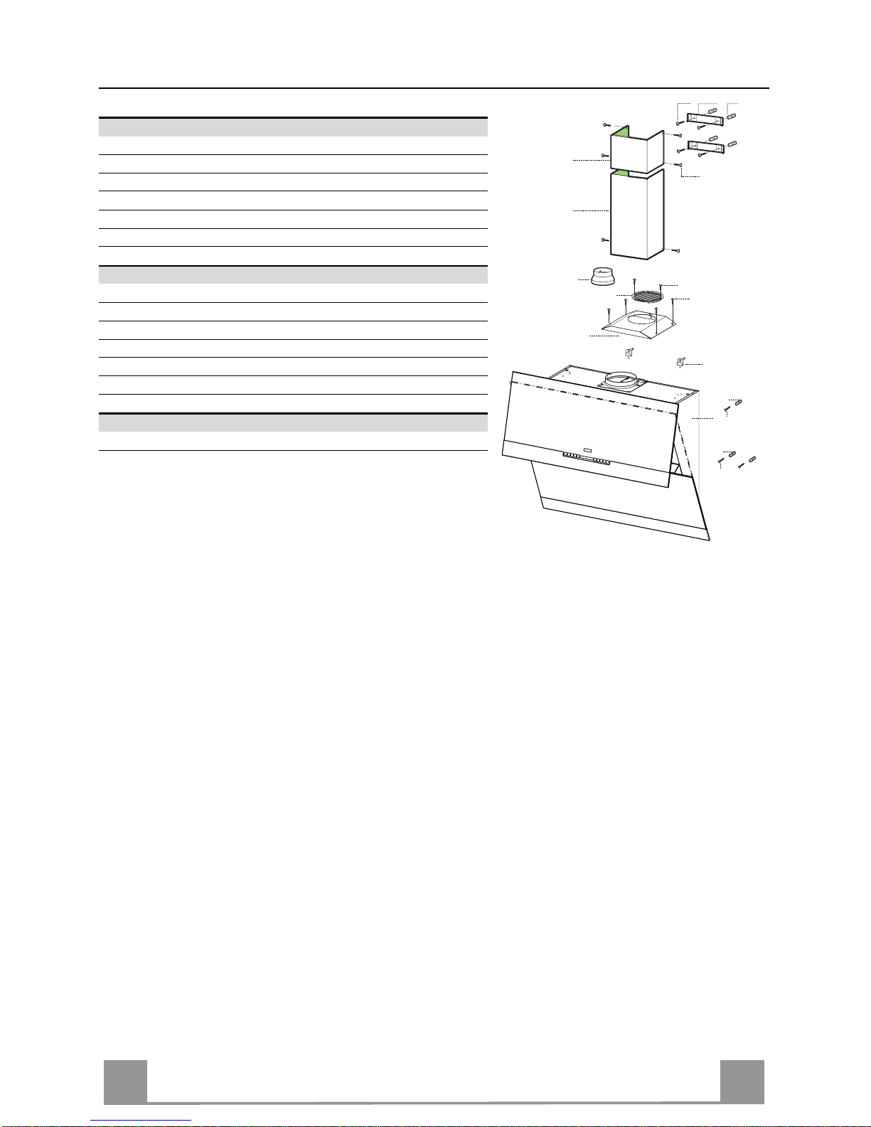
Componenti
Rif. Q.tà Componenti di Prodotto
1 1 Corpo Cappa completo di: Comandi, Luce, Gruppo
Ventilatore, Filtri
2.1 1 Camino Superiore
2.2 1 Camino Inferiore
8 1 Griglia direzionata Uscita Aria
9 1 Flangia riduzione 150-120
16 1 Coperchio filtrante
Rif. Q.tà Componenti di Installazione
7.2.1 2 Staffe Fissaggio Cami no Su periore
11 7 Tasselli
11a 2 Tasselli SB 12/10
12a 7 Viti 4,2 x 44,4
12c 10 Viti 2,9 x 6, 5
12e 2 Viti 2,9 x 9, 5
Q.tà Documentazione
1 Libretto Istruzioni
2.1
2.2
12c
12a
7.2.1 11
11
12a
11
12a
1
16
12c
12d
8
9
11a

IT
6
6
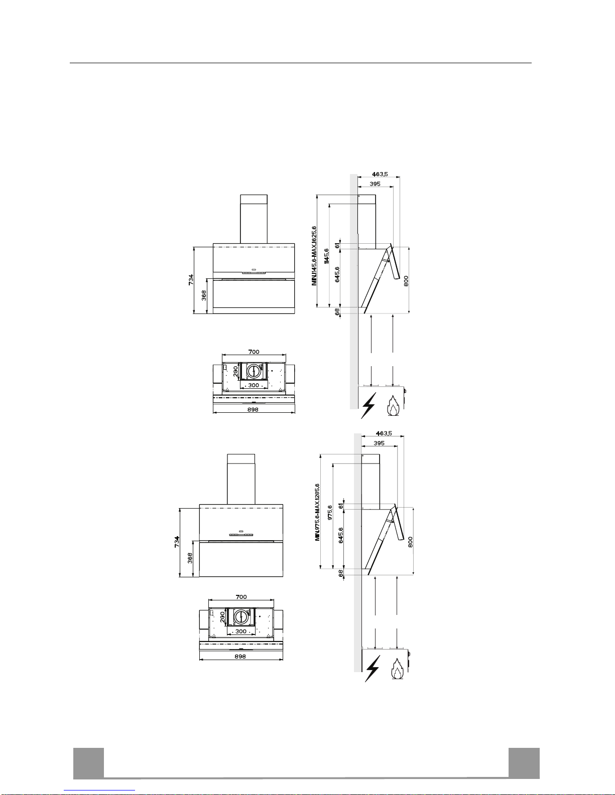
Ingombro
Le dimensioni variano a seconda della versione scelta
Min.
368mm
Min.
368mm
Min.
368mm
Min.
368mm
IT
7
7
11a
1
1
22
200
11
12a
11
12a
3
292 292
960
458
X
1÷2
7.2.1
368
200
743
INSTALLAZIONE
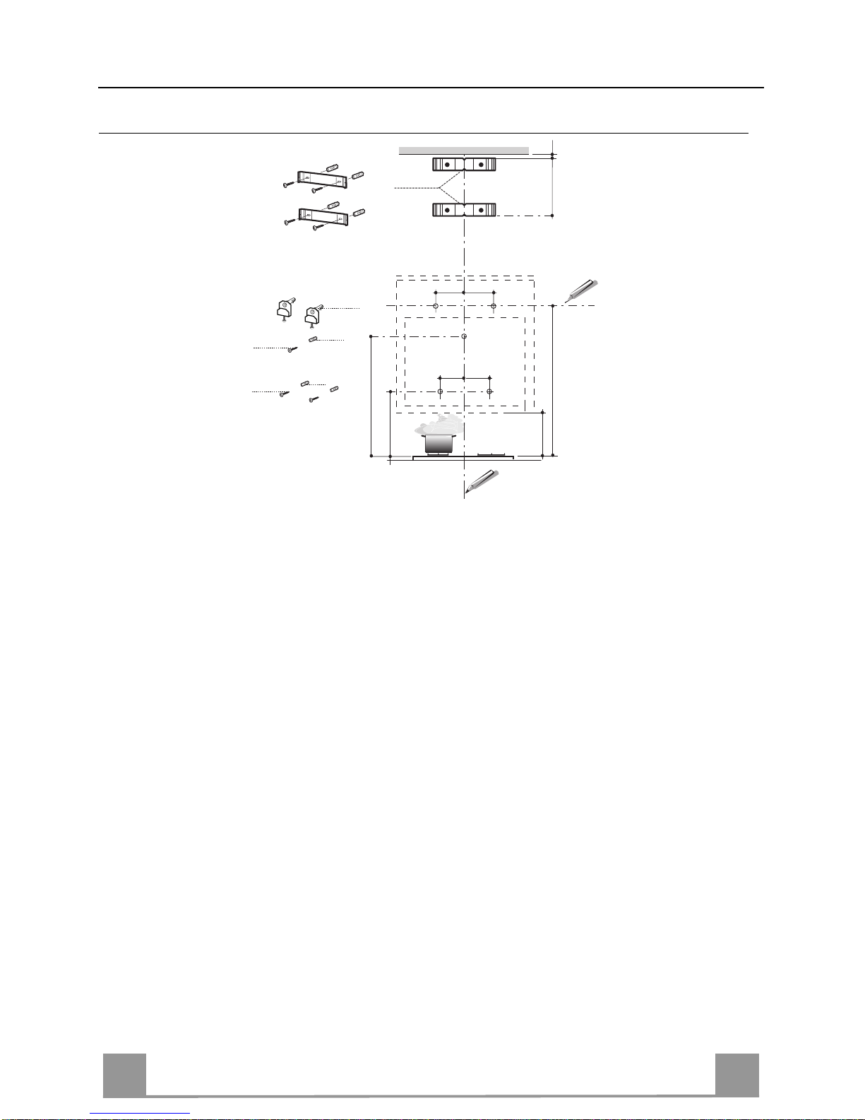
Foratura Parete e Fissaggio Staffe
Tracciare sulla Parete:
• una linea Verticale fino al soffitto o al limite superiore, al centro della zona prevista per il
montaggio della Cappa;
• una linea Orizzontale a 960 mm min . sopra il Pian o di Cottura.
• Segnare un punto (1) sulla linea orizzontale a 292 mm alla destra della linea verticale di riferimento.
• Ripetere questa operazione dalla parte opposta, verificandone il livellamento.
• Segnare come indicato, un punto di riferimento (2) a 200 mm dalla linea Verticale di riferimento, e 458 mm sopra il Piano di Cottura.
• Ripetere questa operazione dalla parte opposta, verificandone il livellamento.
• Segnare come indicato, il punto di riferimento (3) a 743 mm sopra il Piano di Cottura sulla
linea Verticale di riferimento.
• Forare ø 12 mm i punti (1) segnati.
• Forare ø 8 mm i punti (2) e (3) segnati.
• Inserire i tasselli con staffa 11a nei fori (1) e avvitare.
• Inserire il tassello 11 nei fori (2) e (3).
• Appoggiare co me ind icat o l a Staffa 7.2.1 a 1-2 mm dal soffitto o dal limite superiore, allineando il suo centro (intagli) sulla linea Verticale di riferimento.
• Segnare i centri dei Fori della Staffa.
• Appoggiare come ind icato la Staffa 7.2.1 a X mm sotto la p rima staffa (X = altezza Ca mino
Superiore in dotazione), allineando il suo centro (intagli) sulla linea Verticale di riferimento.
• Segnare i centri dei Fori della Staffa.
• Forare ø 8 mm i punti segnati.
• Inserire i tasselli 11 nei fori.
• Fissare le Staffe, utilizzando le Viti 12a (4,2 x 44,4) in dotazione.
IT
8
8
Montaggio Corpo Cappa
• Regolare le due viti Vr, delle staffe 11a, ad inizio corsa (B).
• Agganciare il corpo cappa alle 2 s taff e 11a .
• Collegare la Cappa all’Alimentazione di Rete interponendo un Interruttore bipolare con apertura dei contatti
di almeno 3mm.
• Tenere premuto per 1 Secondo il Tasto “A” (Vedi Pa-
ragrafo USO) pe r apri re il pa nne llo supe r iore .
• Togliere i Filtri Antigrasso agendo sulle apposite maniglie.
• Dall’interno del corpo cappa agire sulle Viti Vr per
livellare il Corpo Cappa.
• Avvitare la vite di sicurezza 11.
• Rimontare i Filtri Antigrasso, chiudere il pannello superiore premendo per 1 Secondo il Tasto “L” (Vedi
Para grafo USO ) .
• Scollegare la Cappa dall’Alimentazione di Rete .
Attenzione: Se l’Anta in fase di Apertur a o Chiusura do-
vesse incontrare un ostacolo si blocca, rimuovendo
l’ostacolo e premendo di nuovo il Tasto l’Anta si Aprirà.
(B)
L
A
11a
Vr
11
Connessioni
USCITA ARIA VERSIONE ASPIRANTE
Per installazione in Versione Aspirante collegare la
Cappa alla tubazione di uscita per mezzo di un tubo
rigido o flessibile di ø150 o 120 mm, la cui scelta è lasciata all'installatore.
• Per collegamento con tubo ø120 mm, inserire la
Flangia di riduzione 9 sull’Uscita del Corpo Cappa.
• Fissare il tubo con adeguate fascette stringitubo. Il
materiale occorrente non è in dotazion e.
• Togliere eventuali Filtri Antiodore al Carbone attivo.
ø 150
9
ø 120

IT
9
9
Uscita aria Versione Filtrante
Per installazione in Versione Filtrante è necessario acquistare il
kit opzionale Cartuccia al carbone attivo.
• Rimuovere l’angolare di fissaggio camino
• Avvitare il coperchio filtrante sull’uscita aria, utilizzando quattro viti 12c (2,9 x 6,5).
• Fissare la Griglia direzionata 8 sull’uscita dell’aria riciclat a con
2 Viti 12d (2,9 x 9,5) in dotazione.
16
12c
12d
8
CONNESSIONE ELETTRICA
• Ricollegare la Cappa all’Alimentazione di Rete.
• Tenere premuto per più di 2 Secondi il Tasto “A” ( Vedi Paragrafo “Uso” ) per aprire il pannello superiore.
• Rimuovere i Filtri antigrasso ( Vedi Paragrafo “Manutenzione”
) e assicurarsi che il connettore del Cavo di alimentazione sia
correttamente inserito nella presa dell’Aspiratore
Montaggio Camino
Camino superiore
• Allargare leggermente le due falde laterali, agganciarle dietro
le Staffe 7.2.1 e richiuderle fino a battuta.
• Fissare lateralmente alle Staffe con 4 Viti 12c (2,9 x 9,5) in
dotazione.
Camino inferiore
• Allargare leggermente le due falde laterali del Camino, agganciarle tra il Camino superiore e la parete e richiuderle fino a
battuta.
• Fissare lateralmente la parte inferiore al Corpo Cappa, con 2
Viti 12c (2,9 x 9, 5) in dot azione.
12c
2.1
2.2
2
7.2.1
12c
IT 110
USO
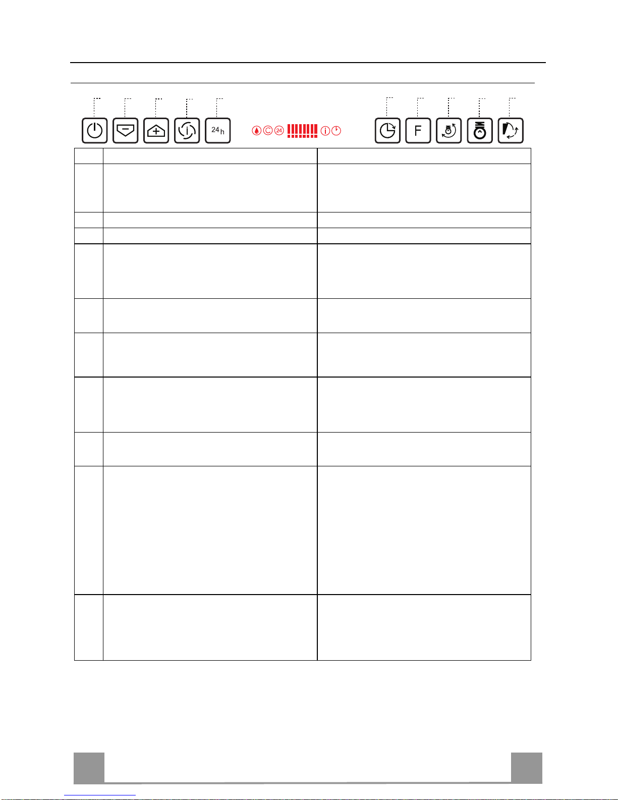
Quadro comandi
Tasto
Funzione Display
A Anta Chiusa: Premuto per circa 2 Secondi apre l’anta
e accende il motore all’ultima velocità impostata.
Anta Aperta: Premuto brevemente Spegne o Accende
il motore.
Visualizza la velocità impostata.
B
Decrementa la velocità di esercizio. Diminuiscono i segmenti accesi.
C
Incrementa la velocità di esercizio. Aumentano i segmenti accesi.
D
Attivabile solo con Anta aperta, tale velocità è temporizzata a 10 minuti, al termine del tempo il sistema
ritorna alla velocità precedentemente impostata. Adatta a fro n tegg ia re le ma s s i me e mis sio n i d i f um i d i
cottura.
Lampeggia
I e i segmenti sul Display sono tutti acce-
si.
Si disattiva premendo il Tasto.
E
Attivabile solo con Anta aperta, attiva il motore ad
una velocità che consente un’aspirazione di 100
m3/h.Non è attivabile se è attiva l’I nte ns iva o il dela y.
Visualizza 24 e i segmenti sul Display da tutti accesi
si spengono uno alla volta ciclicamente.
Si disattiva premendo il Tasto.
F
Attivabile da motore acceso (ad eccezione
dell’intensiva e del 24), attiva lo spegnimento
automatico del Motore e de ll’I lluminazione ritardato
di 30 minuti.
Visualizza il simbolo di un
Orologio che lampeggia.
Si disattiva premendo il Tasto.
G
Effettua il
Reset dell’allar me sat urazione Filtri pre-
mendo il Tasto per circa 3 Secondi quando tutti i carichi sono spenti (motore + luci)
Dopo 100 ore di Funzionamento Visualizza il simbolo
Goccia per segnalare la saturazione dei Filtri Me-
tallici.
Dopo 200 ore di Funzionamento Visualizza
C per
segnalare la saturazione de i Filtri al Carbone Attivo.
H
Modifica l’intensità di Illuminazione ad ogni pressione del Tasto fino ad un Massimo di 5 Livelli in modo
ciclico.
I
Anta Chiusa:
Premuto per circa 2 Secondi apre l’anta a metà e ac-
cende le Luci alla Massima Intens ità con la pos s ibilità
di modificare l’intens ità c ol tasto H.
- Premendo di nuovo il tasto, si spengono le Luci e si
chiude l’Anta.
- Premendo il tasto L, Anta completamente aperta,
motore alla terza velocità e Luci accese.
- Premendo il tasto A, Luci spente e Anta chiusa.
Anta Aperta: Premuto brevemente accende o spegne
le Luc i.
L
Anta Chiusa: Premuto per circa 2 Secondi apre l’anta,
accende il motore alla terza velocità e le luci alla massima intensità.
Anta Aperta: Premuto per circa 2 Secondi spegne
tutto, motore e luce, azzerando qualsiasi funzione
attiva e chiude l’anta.
Comando Blocco Tastiera: è possibile bloccare la tastiera, ad esempio per effettuare la pulizia de l Vetro, q uando la Cappa
ha il M otore e le Luci spente e non so no presenti allarmi , sia con l’anta aperta o chiusa.
Premendo per circa 5 Secondi il tasto F (Delay) si può abilitare o disab ilitare il Blocc o Tas tiera c he è s e mpre confe r mato
con un Beep e un’animazione sulla barra motore del display.
B
A
D
C
E
G
F
I
H
L

IT 111
MANUTENZIONE
Filtri antigrasso metallici
Sono lavabili anche in lavastoviglie, e necessitano di essere lavati
quando sul display appare il simbolo Goccia o almeno ogni 2
mesi circa di utilizzo o più frequentemente, per un uso particolarmente intenso.
Reset del segnale di allarme
• Premere il tasto G per almeno 2 Secondi.
Pulizia Filtri
• Se chiusa, aprire l’Anta premendo per circa 1 secondo il Tasto
A (Vedi USO).
• Togliere i Filtri uno alla volta, spingendoli verso la parte poste-
riore del gruppo e tirando contemp oraneamente verso il basso.
• Lavare i Filtri evitando di piegarli, e lasciarli asciugare prima
di rimontarli. (Un ’eventuale cambiamento del colo re della superficie del filtro, che potrebbe verificarsi nel tempo, non pregiudica assolu tamente l’efficienza dell o stesso.)
• Rimontarli facendo attenzione a mantenere la maniglia verso la
parte visibile esterna.

IT 112
Filtri antiodore al Carbone attivo (Versione Filtrante)
Non è lavabile e non è rigenerabile, va sostituito quando sul display appare il simbolo C o almeno ogni 4 mesi. La segnalazione di Allarme va preventivamente attivata.
Attivazione del segnale di al larme
• Nelle Cappe in Versione Filtrante, la segnalazione di Allarme saturazione Filtri va attivata al
momento dell’installazione o successivamente.
• Spegnere l e Lu ci e il Motore di aspirazione.
• Premere il tasto E per circa 5 Sec . fino all’accension e degli ultimi due segmenti e di tutta la
linea puntinata della barra Motore sul Display.
• Rilasciare il tasto E, l’icona “Orologio” inizia a lampeggiare.
• Entro 3 seco ndi pr emere il Tasto D per abilitazione / disabilitazione Filtri C.A.
• Accensione del simbolo C Allarme saturazione Filtro C.A. ATTIVATO
• Spegnimento del simbolo C Allarme saturazione Filtro C.A. DISATTIVATO
SOSTITUZIONE FILTRO ANTIODORE AL CARBONE ATTIVO
Reset del segnale di allarme
• Premere il tasto G per almeno 2 Secondi.
Sostituzione Filtro
• Se chiusa, aprire l’Anta premendo per circa 1 secondo il Tasto
A (Vedi USO).
• Togliere i Filtri antigrasso.
• Rimuovere i Filtri antiodore al Carbone attivo saturi, come in-
dicato (A).
• Montare i nuovi Filtri, come indicato (B).
• Rimontare i Filtri antigrasso.
A
B
Illuminazione
SOSTITUZIONE LAMPADE
Lampade alogene d a 20 W
• Estrarre la Lampada dal Supporto.
• Sostituirla con una nuova di uguali caratteristiche, facendo attenzione ad inserire correttamente i due spinotti nella sede del
Supporto.
IT 113
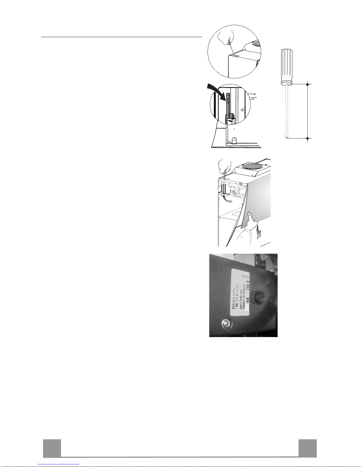
Sostituzione fusibile
Il fusibile agisce solo sul motorino che gestisce il movimento di apertura e chiusura dell’anta. Quindi nel
caso in cui il fusibile si danneggi con l’anta chiusa sarà
necessario sbloccare l’anta manualmen te come descritto
di seguito:
• Rimuovere il coperchio posto sull’angolo in alto a
sinistra.
• Con l’ausilio di un giravite a taglio esercitare una
pressione sulla leva di sbloccaggio, fino ad ottenere
un’apertura dell ’ anta tale da consent irvi di aprirla con
la mano.
• Dopo aver aperto completamente l’anta, togliere i
filtri antigrasso metallici come descritto nel paragrafo
pulizia filtri antigrasso.
• Il fusibile è posizionato in alto a destra, ruotare come
indicato il portafusibile e sostituire il fusibile con uno
di uguali caratteristiche.
• Riposizionare il portafusibile e i filtri antigrasso, verificare il corretto funzionamento della cappa. Nel
caso l’anta continui a non funzionare contattare un
Tecnico autorizzato.
Se la rottura del fusibile si verificasse con l’anta aperta
basta semplicemente togliere i filtri antigrasso e sostituire il fusibile.
Min. 200mm

EN
114
RECOMMENDATIONS AND SUGGESTIONS
The Instructi ons for Us e appl y t o seve ral ver sio ns of this appl
iance. Acco r
d-
ingly, you may find descriptions of in dividual features th at do not apply to
your specific appliance.
INSTALLATION
• The manuf acturer will not be hel d liable for any dama ges resulting from incorrect or i mpr op er ins tal lat ion .
• The minimum safety distance between the cooker top and the extractor
hood is 650 m m (som e m od el s c an be installed at a lower height, please refer to the paragraphs on working dimensions and installation).
• Check that the mains voltage corresponds to that indicated on the rating
plate fixed to the inside of the hood.
• F or Class I appliances, check th at the domestic power suppl y guarantees
adequate earthing.
Connect the extr act or to the e xhaus t flu e throu gh a pipe o f mi nimum diame-
ter 120 mm. The route of the flue must be as short as possible.
• Do not connect the extractor hood to exhaust ducts carrying combustion
fumes (boilers, fireplaces, etc.).
• If the extractor is us ed in conjunctio n with non-elec trical appliances (e.g. gas
burning appl iances), a s ufficient degree of aeration mu st be guarant eed in
the room in orde r to preve nt the backflow of ex haust gas. The kit chen mus t
have an opening communicating directly with the open air in order to
guarantee the entry of clean air.
USE
• The extractor hood has been designed exclusively for domestic use to eliminate kitchen smells.
• Never use the hood for purposes other than for which it has been designed.
• Never le a ve hi gh na ke d fl a me s unde r the ho od wh en i t is in op er at ion .
• Adjust the flame in te nsity to direct i t o nto the bo ttom o f the pan only, m aking
sure that it does not engulf the sides.
• Deep fat f ryers must be conti nuously monit ored during use: overheated oil
can burst into flames.
• Do not flambè under the range hood; risk of fire
• This appli ance is not inten ded for use by pers ons (including chi ldren) with
reduced physi cal, sensory or m ental capabi lities, or lack o f experience an d
knowledge, unl ess th ey have been g iven su pervis ion o r instr ucti on con cern ing use of the appliance by a person responsible for their safety.
• Children should be s up ervised to ens ur e that they do not pl a y wi th t he appliance.
MAINTENANCE
• Switch off or unplug t he a ppliance from the m ai ns s up ply be fo re ca rr yi n g ou t
any maintenance work.
• Clean and/or replace the Filters after the specified time period (Fire hazard).
• Clean the hood using a damp cloth and a neutral liquid detergent.
The symbol on the product or on its packaging indicates that this product may not be treated
as household waste. Instead it shall be handed over to the applicable collection point for the
recycling of el ec trical and elec tronic equipmen t. By ensuring thi s product i s di s p osed of correctl y ,
you will help prevent potential negative consequences for the environment and human health,
which could otherwise be caused by inappropriate waste handling of this product. For more
detailed information about recycling of this product, please contact your local city office, your
household waste disposal service or the shop where you purchased the product.
EN
115
CHARACTERISTICS
Components
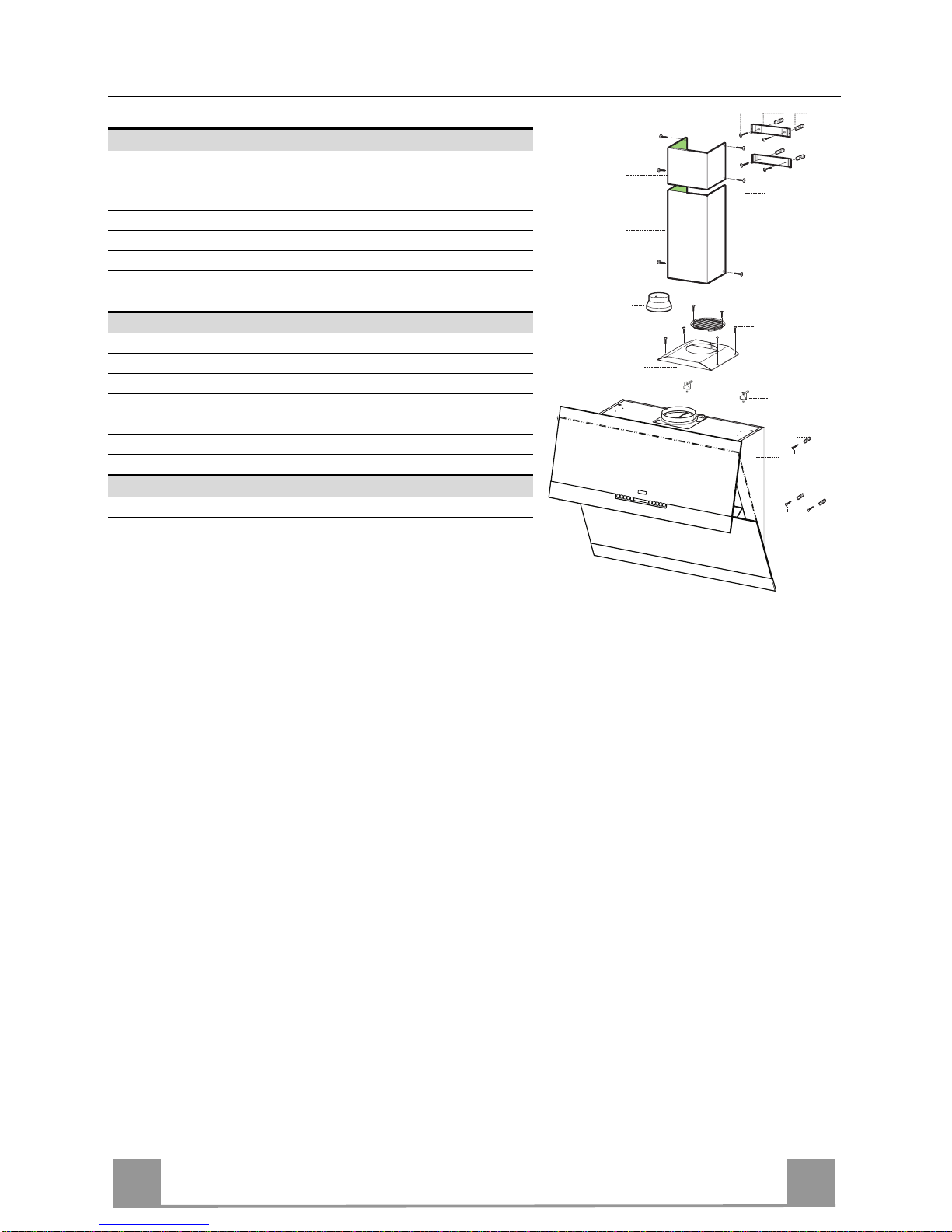
Ref. Q.ty Product components
1 1 Cooker hood with control unit, l ights, blower unit, filters
2.1 1 Upper chimney
2.2 1 Lower chimney
8 1 Air outlet grid
9 1 Reducer f lange Ø 150-120
16 1 Cover for recycling version
Ref. Q.ty Installation components
7.2.1 2 Fixing brackets for upper chimney
11 7 Plugs
11a 2 Plugs SB 12/10
12a 7 Screws 4,2 x 44,4
12c 10 Screws 2,9 x 6,5
12e 2 Screws 2,9 x 9,5
Q.ty Documentation
1 Instruction booklet
2.1
2.2
12c
12a
7.2.1 11
11
12a
11
12a
1
16
12c
12d
8
9
11a
EN
116
Dimensions
The dimensions depend on the chosen vers ion
Min.
368mm
Min.
368mm
Min.
368mm
Min.
368mm
EN
117
INSTALLATION
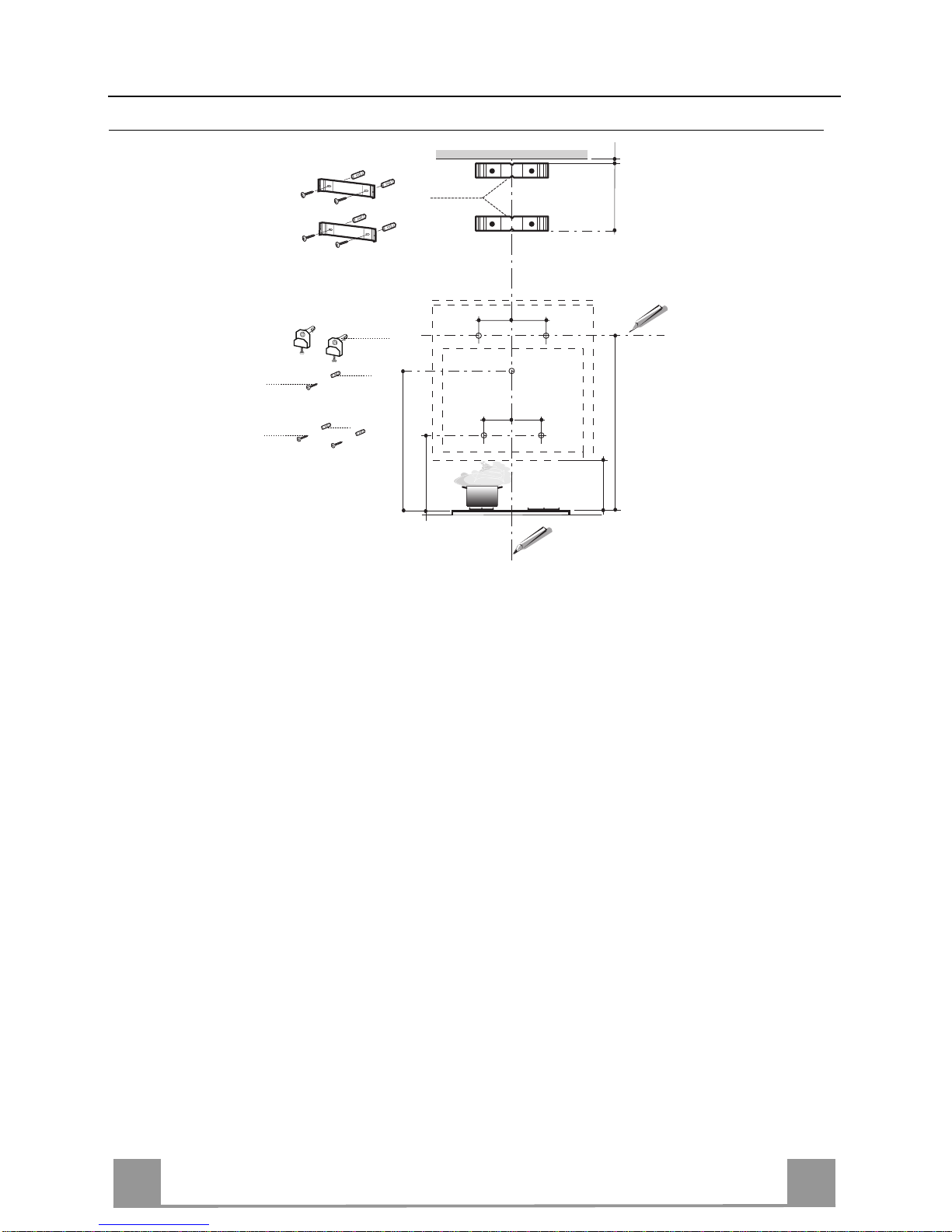
Wall drilling and bracket fixing
As a first step, proceed with the following drawings:
• a vertical line up to the ceiling or up to the upper limit, at the centre of the area in which the
hood is to be fitted;
• a horizontal line at a minimum 960 mm above the cooker top.
• Mark a point (1) on the horizontal line, 292 mm to the right of the vertical reference line.
• Repeat this operation on th e other side, checking that the two marks are levelled.
• Mark a reference p oint (2) as indi cated at 200 mm from the vertic al reference line and 458
mm above the cooker t op.
• Repeat this operation on th e other side, checking that the two marks are levelled.
• Mark a reference point (3) at 743 mm above the cooker top on the vertical reference line.
• Drill at the marked points (1), using a ø 12 mm drill bit.
• Drill at the marked points (2) and (3), using a ø 8 mm drill bit.
• Insert the bracket plugs 11a into the holes (1) and tighten the screws.
• Insert plug 11 into holes (2) and (3).
• Place bracket 7.2.1 on the wall, about 1-2 mm from the ceiling or from the upper limit,
aligning the centre (notch) with the vertical reference line.
• Mark the wall at the centres of the bracket holes.
• Place the bracket 7.2.1 on the wall at X mm belo w the first bracket (X = heigh t of the upper
chimney section) , aligning the centre (notch) with the vertical line.
• Mark the wall at the centres of the bracket holes.
• Drill ø 8 mm holes at all the marked centre points.
• Insert the wall plugs 11 in the hole s.
• Fix the brackets usin g th e 12a screws (4,2 x 44,4) supplied with the hood.
11a
1
1
22
200
11
12a
11
12a
3
292 292
960
458
X
1÷2
7.2.1
368
200
743
EN
118
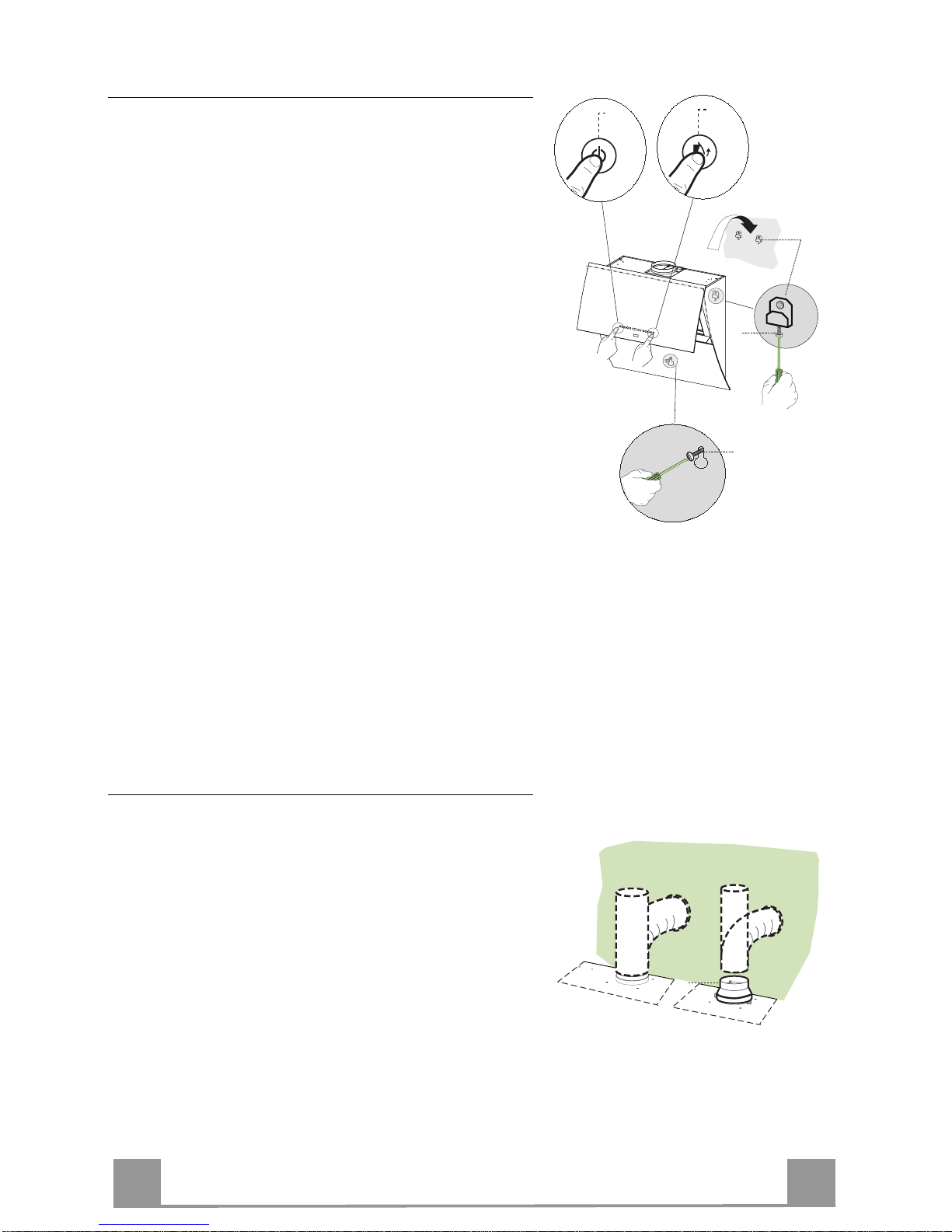
Hood body mounting
• Firstly, it is necessary to adjust the two Vr-scr ews of
the 11a-brackets, at minimun (B).
• Hang the hood body on the two bra ck e ts 11a .
• Connect the hood to the mains supply by means of a
bipolar switch with at le as t 3 mm contact gap.
• Press the “A”-key for one second (see Part USE) to
open the upper pa ne l.
• Remove the metal filters.
• In order to align the hood it is necessary to adjust the
Vr-screws from inside the hood.
• Fasten the safety screw 11.
• Fit again the metal filters into their seat s and clo se the
upper panel by pressing “L”-key for one second (see
Part USE).
• Disconnect the hood from the mains s upply.
Attention: the uppe r pa nel stops if a ny barrie r occurs i n its
way during the panel opening or closing. To open the panel
it is enough to remove the barrier and pres s the key once
again.
(B)
L
A
11a
Vr
11
Connections
DUCTED VERSION AIR EXHAUST SYSTEM
When installing t he ducted versi on, conn ect the hood to
the chimney using either a flexible or rigid pipe ø 150
or 120 mm, the choice of which is left to the installer.
• To install a ø 120 mm air exhaust connection, insert
the reducer flange 9 on the hood body outlet.
• Fix the pipe in position using sufficient pipe clamps
(not supplied).
• Remove possible charcoal filters.
ø 150
9
ø 120
EN
119
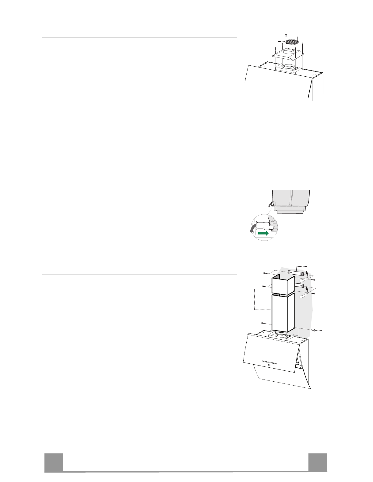
RECYCLING VERSION AIR OUTLET
To install the hood in recycling version, the optional charcoal
filter kit must be purchased.
• Remove the chimney angle bracket.
• Screw the filter cover onto the air outlet, using four screws 12c
(2.9 x 12.5).
• Fix the air outlet grid 8 on the recirculation air outlet using the
2 screws 12d (2,9 x 9,5) provided.
16
12c
12d
8
ELECTRICAL CONNECTION
• Connect the hood to the mains supply.
• Open the upper panel by pressing the A-key (See Part “USE” )
for at least 2 seconds.
• Remove the metal filters (See Part “MAINTENANCE”) and
make sure that the connector piece of the supply cable is correctly inside the hood socket.
Chimney assembly
Upper exhaust Chimney
• Slightly widen the two sides of the upper chimney and hook
them behind the brackets 7.2.1, making sure that they are well
seated.
• Secure the sid es to the brackets usin g the 4 screws 12c (2,9 x
9,5) supplied.
Lower exhaust Chimney
• Slightly widen the two sides of the chimney and hook them
between the upper chimney and the wall, making sure that they
are well seated.
• Fix the lower part laterally to the hood body using the 2 screws
12c (2,9 x 9,5) supplied.
12c
2.1
2.2
2
7.2.1
12c
EN
220
USE
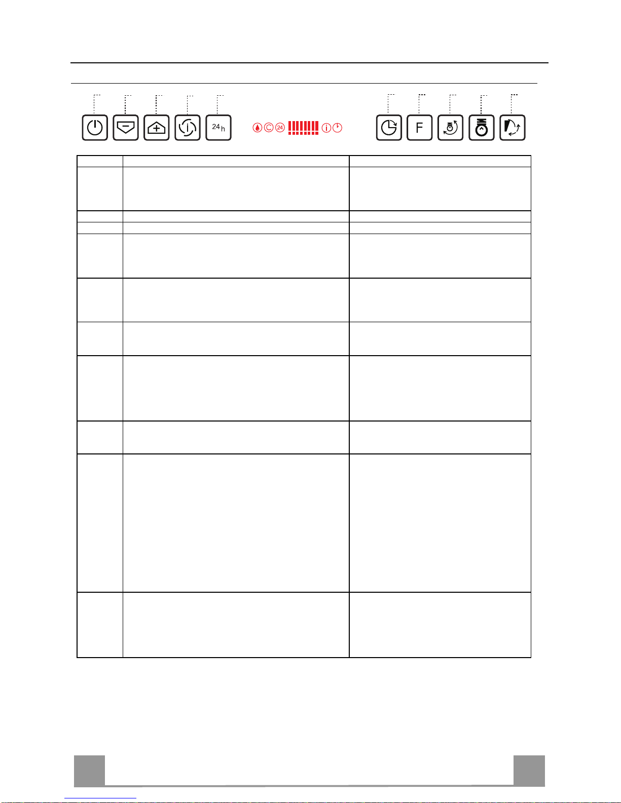
Control panel
B
A
D
C
E
G
F
I
H
L
Button Function Display
A Door Closed: Press and hold for approximately 2 Sec-
onds to open the door and turn the motor on at t he last
speed set.
Door Open: Press briefly to turn the motor Off or On.
Displays the set speed.
B Decrease the working speed. The number of lighted segments decreases.
C Increase the working speed. The number of lighted segments increases.
D Can only be activated with Door Open. This speed is
timed to run for 10 minutes. At the end of this time the
system will auto matically return to t he speed set be fore.
Suitable to de al with maximum levels of cooking fumes .
The indicator I flashes and all the segments
on the Display are lit.
It is disabled by pressing the Button.
E Can only be activated with Door Open. Starts the Motor
at a speed that allows suction of 100 m3/h. Cannot be
activated if Intensive or Delay are active.
Displays 24 and the segments on the Display
all light up and then turn off one at a time in
cycle.
It is disabled by pressing the Button.
F Can be activa te d with motor on (except for intensive and
24 mode). Activates automatic shutdown of the Motor
and the Lighting with a 30’ delay.
Displays a flashing Clock symbol.
It is disabled by pressing the Button.
G Performs a Reset of the Filter saturat ion alar m when the
button is pressed for approximately 3 seconds when all
the users (motor + lights) are turned off.
After 100 hours in operation the Drop symbol is displayed to indicate saturation of the
Metal Grease Filters.
After 200 hours in operation the letter C is
displayed to indicate saturation of the Activated Charcoal filters.
H Modifies the intensity of the Lighting each time the But-
ton is pressed, with a maximum of 5 levels, accessed in
cycle.
I Door Closed:
When pressed and held for approximately 2 seconds
opens the door half way and turns the lighting on to
maxi mum int e nsity. T he int e nsit y ca n be m o d i fie d us i n g
button H.
- When the button is presse d a ga in, the lighting turns off
and the door closes.
- Press L for door fully open, motor at speed three and
lighting on.
- Press A for lighting off and door closed.
Door Open: Press briefly to turn the lighting On
or Off.
L Door Closed: Press and hold for approximately 2 Sec-
onds to open the door, turn the motor on at speed three
and turn the lighting on at maximum intensity.
Door Open: When pressed and held for approximately 2
seconds turns off the motor and the lighting, cancelling
any function that may be active and closing the door.
Keyboard Lock: it is possible to lock the keyboard, for example when cleaning the Glass, when the Hood has Motor and
Lights turned off and when no alarms have been triggered, either with the door open or closed.
Press F (Delay) for approximately 5 Seconds to enable or disable the Keyboard Lock, which is always confirmed by a
Beep and an animation on the display motor bar.
EN
221
MAINTENANCE
Metal grease filters
Filters can be washed in the dish machine. They need to be
washed when Drop-sign appears on the display or in any case
every 2 months, or even more frequently in case of particularly
intensive use of the hood.
Alarm reset
• Press the G–key for at least 2 seconds.
Cleaning the filters
• Open the upper panel by pressing the A-key for 1 second (see
Part USE).
• Remove the filters one by one pushing them towards the back
side of the hood unit and simultaneously pulling downwards.
• Any kind of bending of the filters has to be avoided when
washing them. Before fitting them again into the hood make
sure that they are completely dry. (The colour of the filter surface may change throughout the time but this has no influence
to the filter efficiency).
• When fitting the filters into the hood pay attention that they are
mounted in correct position the handle facing outwards.
EN
222
Charcoal filter (recycling version)
This filter cannot be washed or regenerated. It must be replaced when the C appears on the
display or at least once every 4 months. The filter saturation alarm has to be activated already
before.
Activation of the alar m signal
• In the recycling version hoods the filter saturation alarm must be activated during the installation or later.
• Switch off the hood and the lights.
• Press the E-key for about 5 seconds until the last two segments of the motor LEDS are lit on
the display.
• By releasing the E-key the clock icon starts to flash.
• Within 3 seconds press the D-key to activate/deactivate charcoal filter saturat ion alarm.
• C-symbol lit - charcoal filter saturation alarm ACTIVATED.
• C-symbol unlit - charcoal filter saturation alarm DEACTIVATED.
REPLACING THE CHARCOAL FILTER
Alarm reset
• Press the G-key for at least 2 seconds.
Replacing the filter
• Open the upper panel by pressing the A-key for about a second
(see Part USE).
• Remove the metal filters.
• Remove the saturated charcoal filter as indicated (A).
• Fit the new filters as indicated (B).
• Put the metal grease filters in their seats.
A
B
Lighting
LIGHT REPLACEMENT
20 W halogen light.
• Extract the lamp from the lamp holder by pulling gently.
• Replace with another of the same type, making sure that the
two pins are properly inserted in the lamp holder socket holes.

EN
223
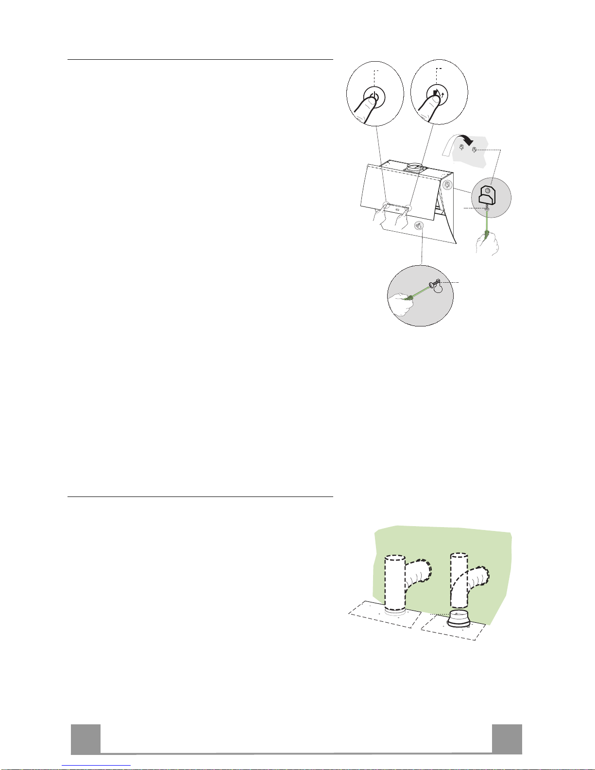
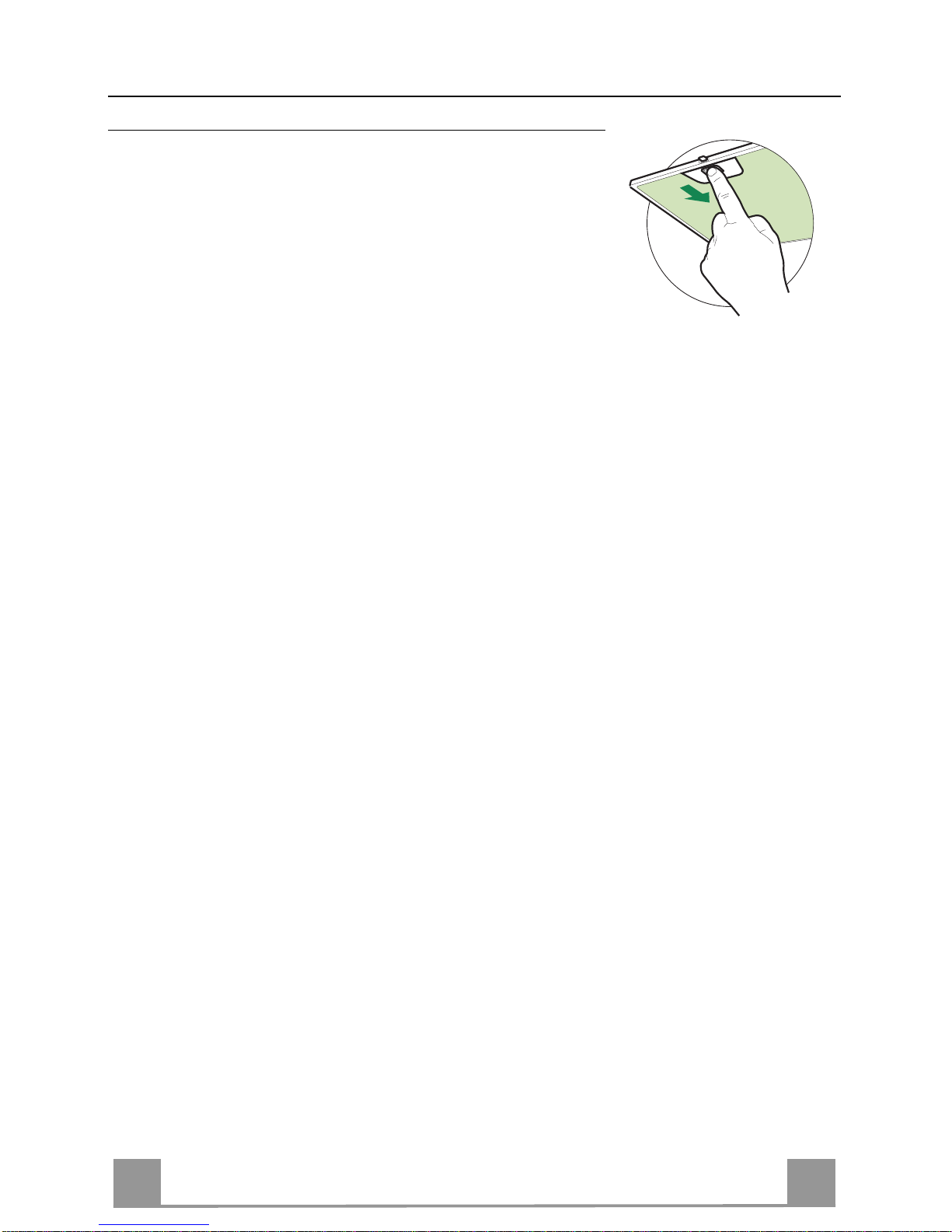
Replacing the fuser
The hood panel opening and closing mechanism is controlled by a starter motor which is activated by a fuser.
This fuser works only on th e starter motor. In case the
fuser gets damaged when the panel is closed it is be
necessary to manually unblock the panel. In this case
proceed as follo ws:
• Remove the cover placed up on the left side.
• Press the releasing lever with the screwdriver as
much as necessary to enable the manual opening of
the panel.
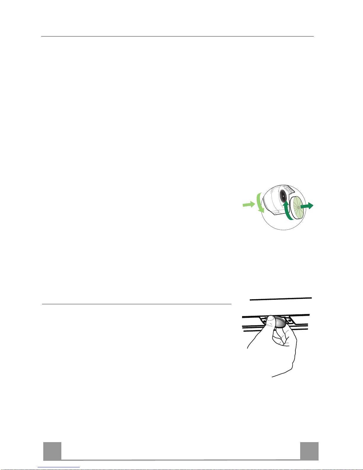
• After having completely opened the panel remove the
metal grease filters, as explained in the part concerning the filter cleaning.
• The fuser is placed up on the right side. Turn the
fuser holder as indi cated. Replace the fuser with o ne
having the same features.
• Pu t the fuser holder and grease filters into th eir place
again. Make sure that th e hood functi ons co rrectly. In
case the panel doesn ’t work correctly it is necessary
to contact an authorized techn ician.
If the fuser gets damaged being the panel open, it is sufficient to simply remove the grease filters and replace
the fuser.
Min. 200mm
 Loading...