

Franke FSN 908 BK A, FSN 908 WH A Instructions For Use And Installation

Instructions for use and installation
Cooker Hood
Istruzioni per l’uso e l’installazione
Cappa
Mode d’emploi et installation
Hotte de Cuisine
Bedienungsanleitung und Einrichtung
Dunstabzugshaube
Kullanım ve montaj talimatları
Davlumbaz
FSN 908 BK A - FSN 908 WH A
GB
IT
FR
DE
TR

2
2
INDEX
RECOMMENDATIONS AND SUGGESTIONS ..................................................................................................................... 3
CHARACTERISTICS ............................................................................................................................................................. 4
INSTALLATION...................................................................................................................................................................... 5
USE ...................................................................................................................................................................................... 10
MAINTENANCE................................................................................................................................................................... 11
INDICE
CONSIGLI E SUGGERIMENTI............................................................................................................................................ 13
CARATTERISTICHE............................................................................................................................................................ 14
INSTALLAZIONE ................................................................................................................................................................. 15
USO...................................................................................................................................................................................... 20
MANUTENZIONE ................................................................................................................................................................ 21
SOMMAIRE
CONSEILS ET SUGGESTIONS.......................................................................................................................................... 23
CARACTERISTIQUES......................................................................................................................................................... 24
INSTALLATION.................................................................................................................................................................... 25
UTILISATION ....................................................................................................................................................................... 30
ENTRETIEN......................................................................................................................................................................... 31
INHALTSVERZEICHNIS
EMPFEHLUNGEN UND HINWEISE ................................................................................................................................... 33
CHARAKTERISTIKEN......................................................................................................................................................... 34
MONTAGE ........................................................................................................................................................................... 35
BEDIENUNG........................................................................................................................................................................ 40
WARTUNG........................................................................................................................................................................... 41
IÇERIKLER
TAVSIYELER VE ÖNERILER.............................................................................................................................................. 43
ÖZELLIKLER........................................................................................................................................................................ 44
MONTAJ............................................................................................................................................................................... 45
KULLANIM ........................................................................................................................................................................... 50
BAKIM .................................................................................................................................................................................. 51
EN
IT
FR
DE
TR
EN
3
3
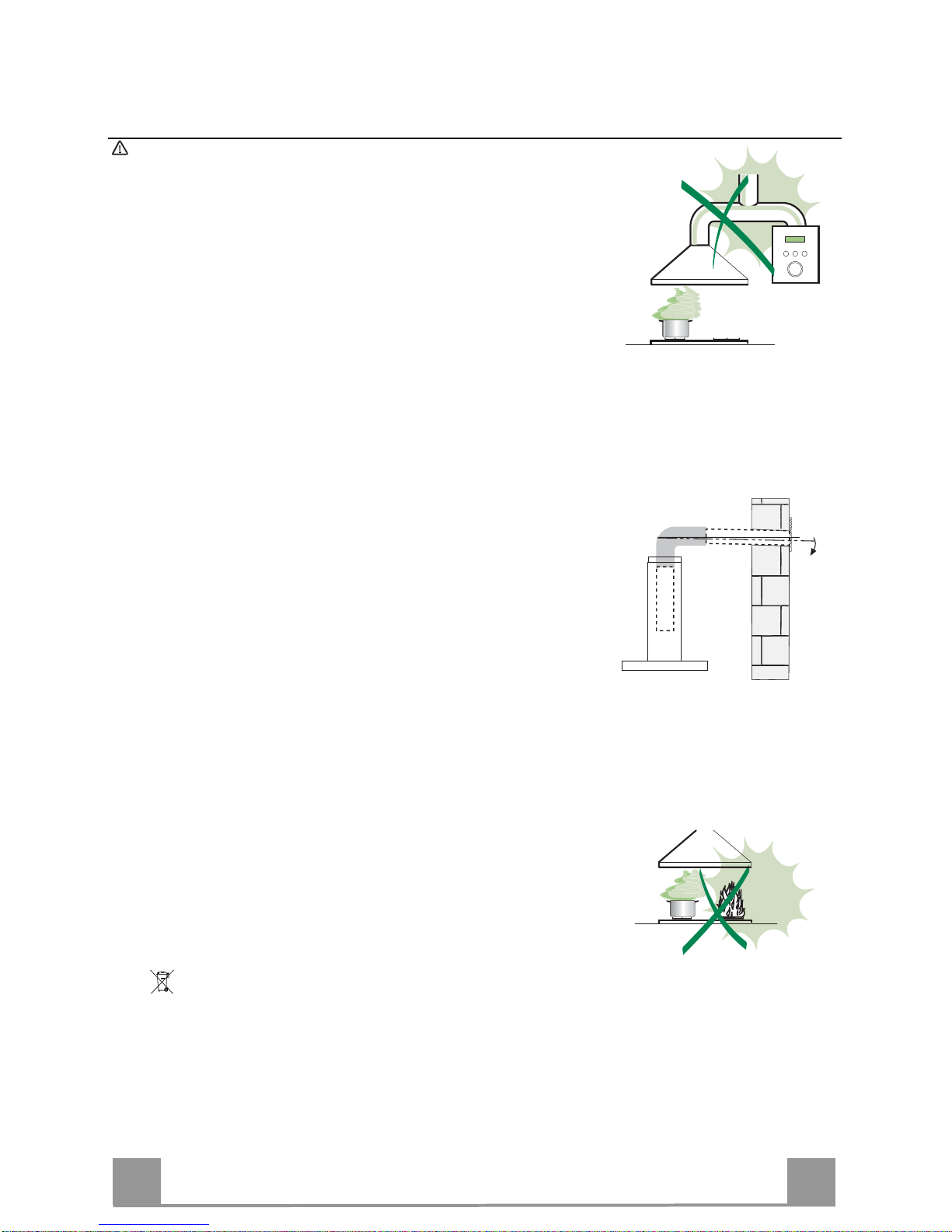
RECOMMENDATIONS AND SUGGESTIONS
The Instructions for Use apply to several versions of this appliance. Accordingly, you may find
descriptions of individual features that do not apply to your specific appliance.
INSTALLATION
• The manufacturer will not be held liable for any damages resulting from incorrect or improper
installation.
• The minimum safety distance between the cooker top and the extractor hood is 650 mm (some
models can be installed at a lower height, please refer to the paragraphs on working dimensions
and installation).
• Check that the mains voltage corresponds to that indicated on the rating plate fixed to the inside of
the hood.
• For Class I appliances, check that the domestic power supply guarantees adequate earthing.
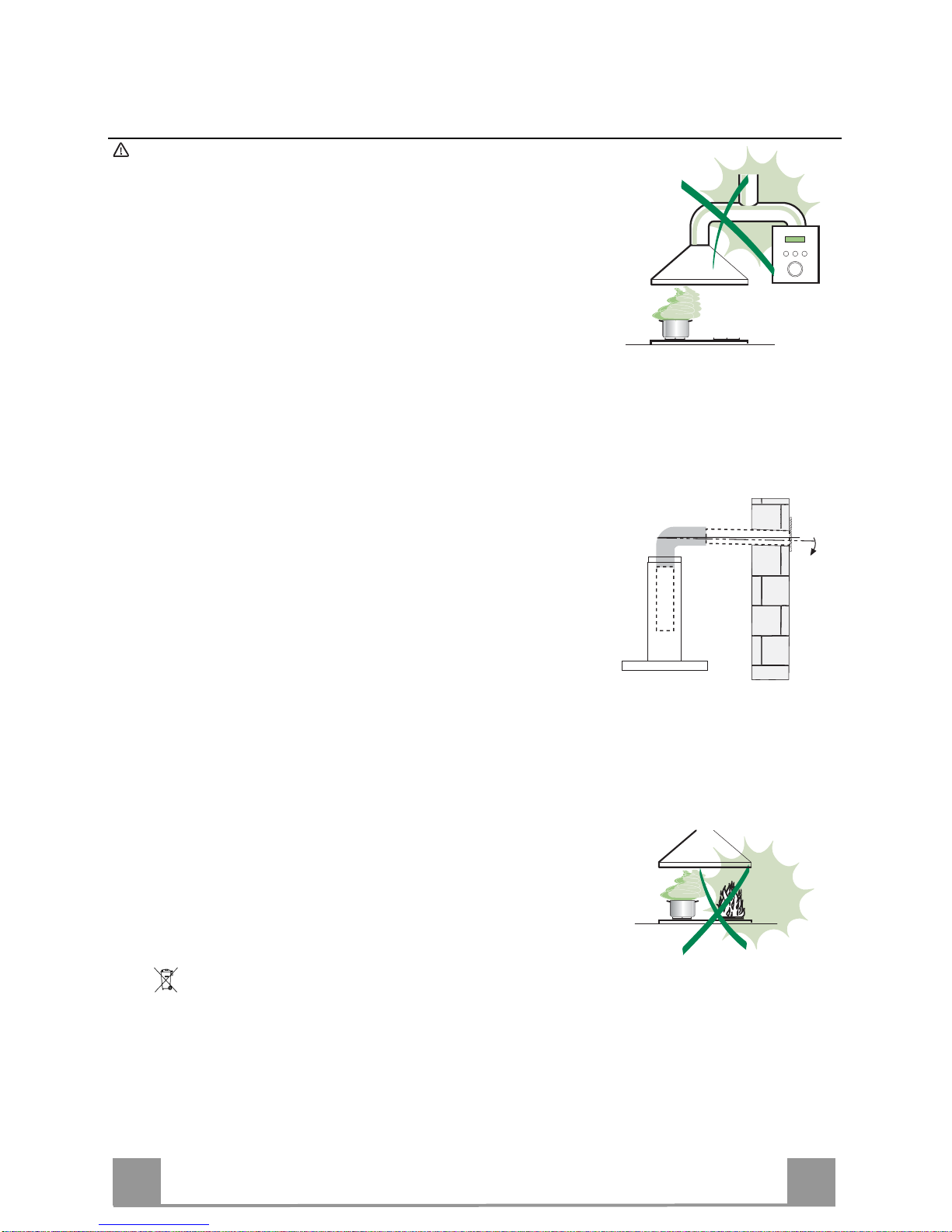
Connect the extractor to the exhaust flue through a pipe of minimum diameter 120 mm. The route
of the flue must be as short as possible.
• Do not connect the extractor hood to exhaust ducts carrying combustion fumes (boilers, fireplaces,
etc.).
• If the extractor is used in conjunction with non-electrical appliances (e.g. gas burning appliances), a
sufficient degree of aeration must be guaranteed in the room in order to prevent the backflow of
exhaust gas. The kitchen must have an opening communicating directly with the open air in order
to guarantee the entry of clean air. When the cooker hood is used in conjunction with appliances
supplied with energy other than electric, the negative pressure in the room must not exceed 0,04
mbar to prevent fumes being drawn back into the room by the cooker hood.
• In the event of damage to the power cable, it must be replaced by the manufacturer or by the
technical service department, in order to prevent any risks.
• If the instructions for installation for the gas hob specify a greater distance specified above, this has
to be taken into account. Regulations concerning the discharge of air have to be fulfilled.
USE
• The extractor hood has been designed exclusively for domestic use to eliminate kitchen smells.
• Never use the hood for purposes other than for which it has been designed.
• Never leave high naked flames under the hood when it is in operation.
• Adjust the flame intensity to direct it onto the bottom of the pan only, making sure that it does not
engulf the sides.
• Deep fat fryers must be continuously monitored during use: overheated oil can burst into flames.
• Do not flambè under the range hood; risk of fire
• This appliance is not intended for use by persons (including children) with reduced physical, sensory or mental capabilities, or lack of experience and knowledge, unless they have been given supervision or instruction concerning use of the appliance by a person responsible for their safety.
• Children should be supervised to ensure that they do not play with the appliance.
• “ CAUTION: Accessible parts may become hot when used with cooking appliances.”.
MAINTENANCE
• Switch off or unplug the appliance from the mains supply before carrying out any maintenance
work.
• Clean and/or replace the Filters after the specified time period (Fire hazard).
• Clean the hood using a damp cloth and a neutral liquid detergent.
The symbol on the product or on its packaging indicates that this product may not be treated as household waste. Instead it shall be handed over to the
applicable collection point f or the recycling of electrical and electronic equipment. By ensuring this product is di sposed of correctly, you will help prevent pote ntial negative
consequences for the environme nt and human health, which could otherwi se be caused by inappropriate waste handling of this product. For more detailed information
about recycling of this pr oduct, please contact your local city office, your household wa ste disposal service or the shop where you purchased the prod uct
.
2°
EN
4
4
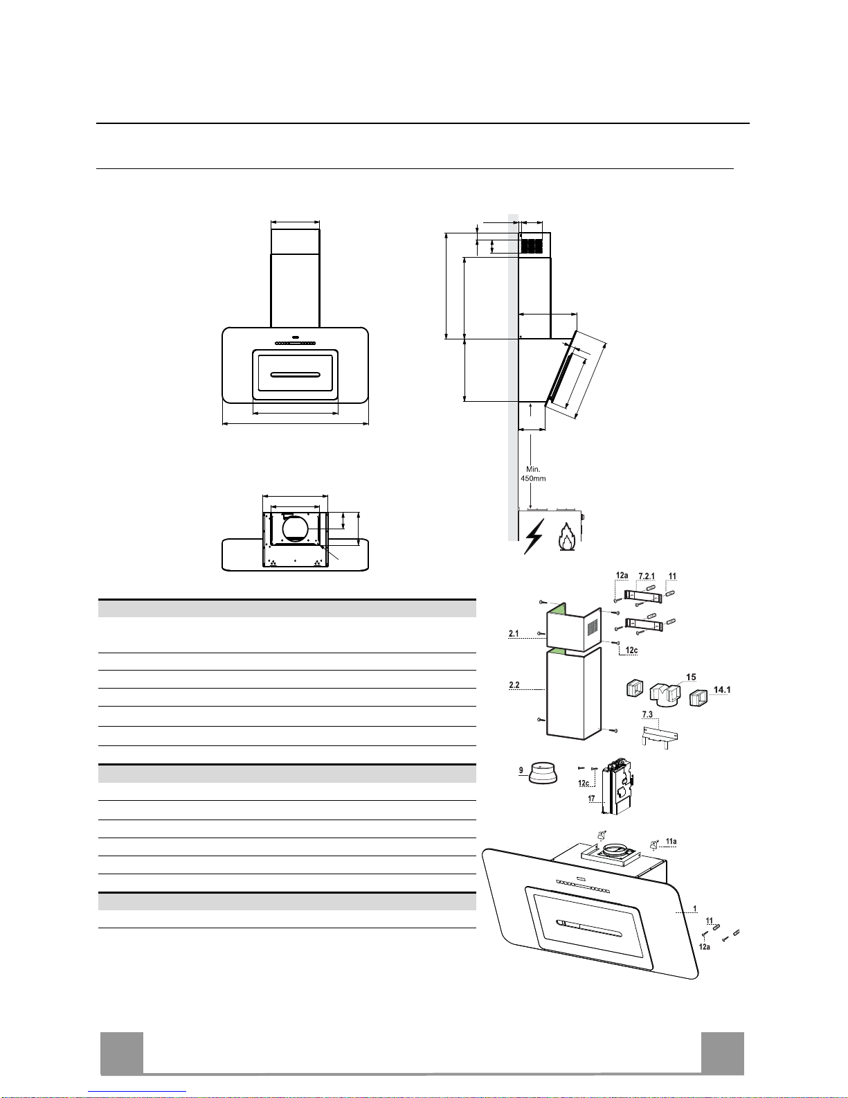
CHARACTERISTICS
Dimensions
898
300
520
41.5
81
19.2 126
Min.625 - Max.980
380
500
330
35
357
160
500
300
200
R
5
400
100
Components
Ref. Q.ty Product Components
1 1 Hood Body, complete with: Controls, Light, Blower,
Filters
2.1 1 Upper Section
2.2 1 Lower Section
9 1 Flange
14.1 2 Air Outlet Connection Extension
15 1 Air Outlet Connection
17 1 Control board unit
Ref. Q.ty Installation Components
7.2.1 2 Upper Chimney Section Fixing Brackets
7.3 1 Air Outlet Connection Support
11 6 Wall Plugs
11a 2 Wall Plugs SB 12/10
12a 6 Screws 4,2 x 44,4
12c 8 Screws 2,9 x 6,5
Q.ty Documentation
1 Instruction Manual

EN
5
5
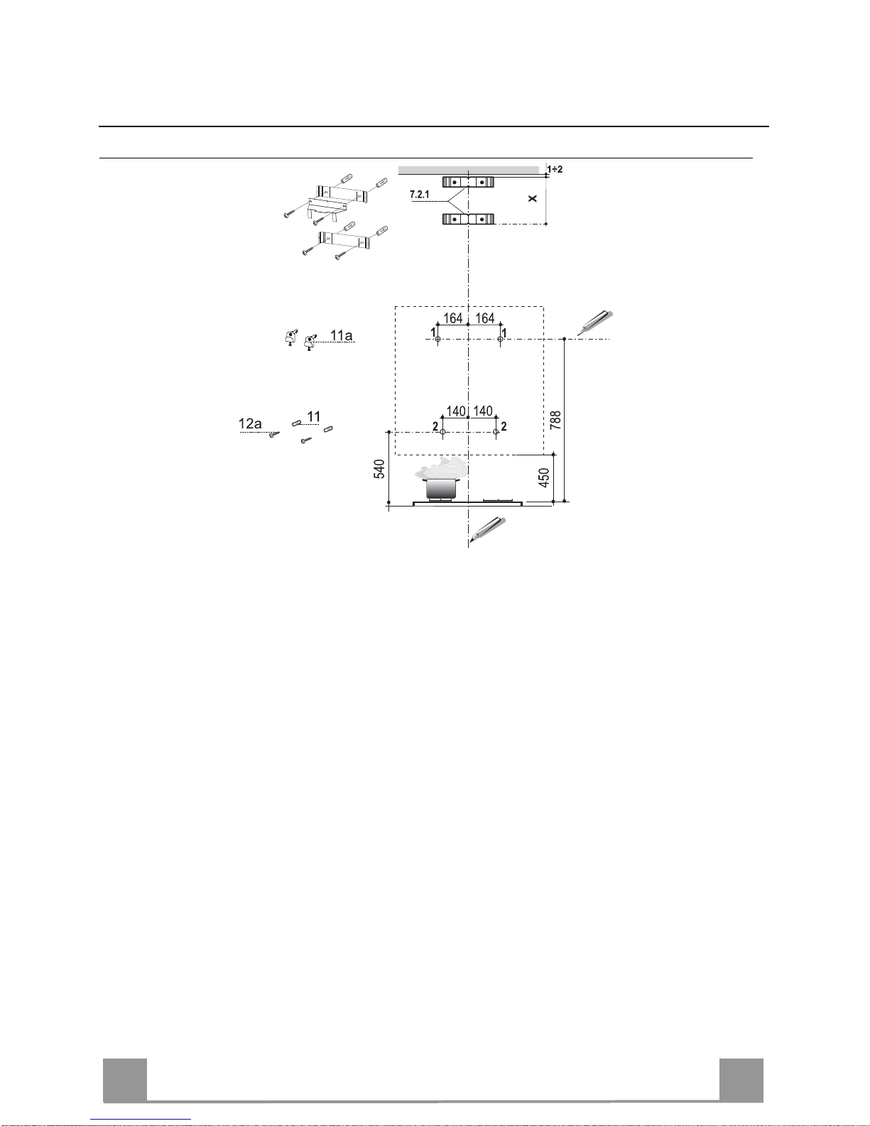
INSTALLATION
Wall drilling and bracket fixing
As a first step, proceed with the following drawings:
• a vertical line up to the ceiling or up to the upper limit, at the centre of the area in which the hood
is to be fitted;
• a horizontal line at a minimum 788 mm above the cooker top.
• Mark a point (1) on the horizontal line, 164 mm to the right of the vertical reference line.
• Repeat this operation on the other side, checking that the two marks are levelled.
• Mark a reference point (2) as indicated at 140 mm from the vertical reference line and 540 mm
above the cooker top.
• Repeat this operation on the other side, checking that the two marks are levelled.
• Drill at the marked points (1), using a ø 12 mm drill bit.
• Drill at the marked points (2) using a ø 8 mm drill bit.
• Insert the bracket plugs 11a into the holes (1) and tighten the screws.
• Insert plug 11 into holes (2).
• Place bracket 7.2.1 on the wall, about 1-2 mm from the ceiling or from the upper limit, aligning
the centre (notch) with the vertical reference line.
• Mark the wall at the centres of the bracket holes.
• Place the bracket 7.2.1 on the wall at X mm below the first bracket (X = height of the upper
chimney section), aligning the centre (notch) with the vertical line.
• Mark the wall at the centres of the bracket holes.
• Drill ø 8 mm holes at all the marked centre points.
• Insert the wall plugs 11 in the holes.
• Fix the lower bracket 7.2.1 using the 12a screws (4,2 x 44,4) supplied.
• Fix the upper bracket 7.2.1 and the air outlet connection support 7.3 together using the 2 screws
12a (4,2 x 44,4) supplied.
EN
6
6
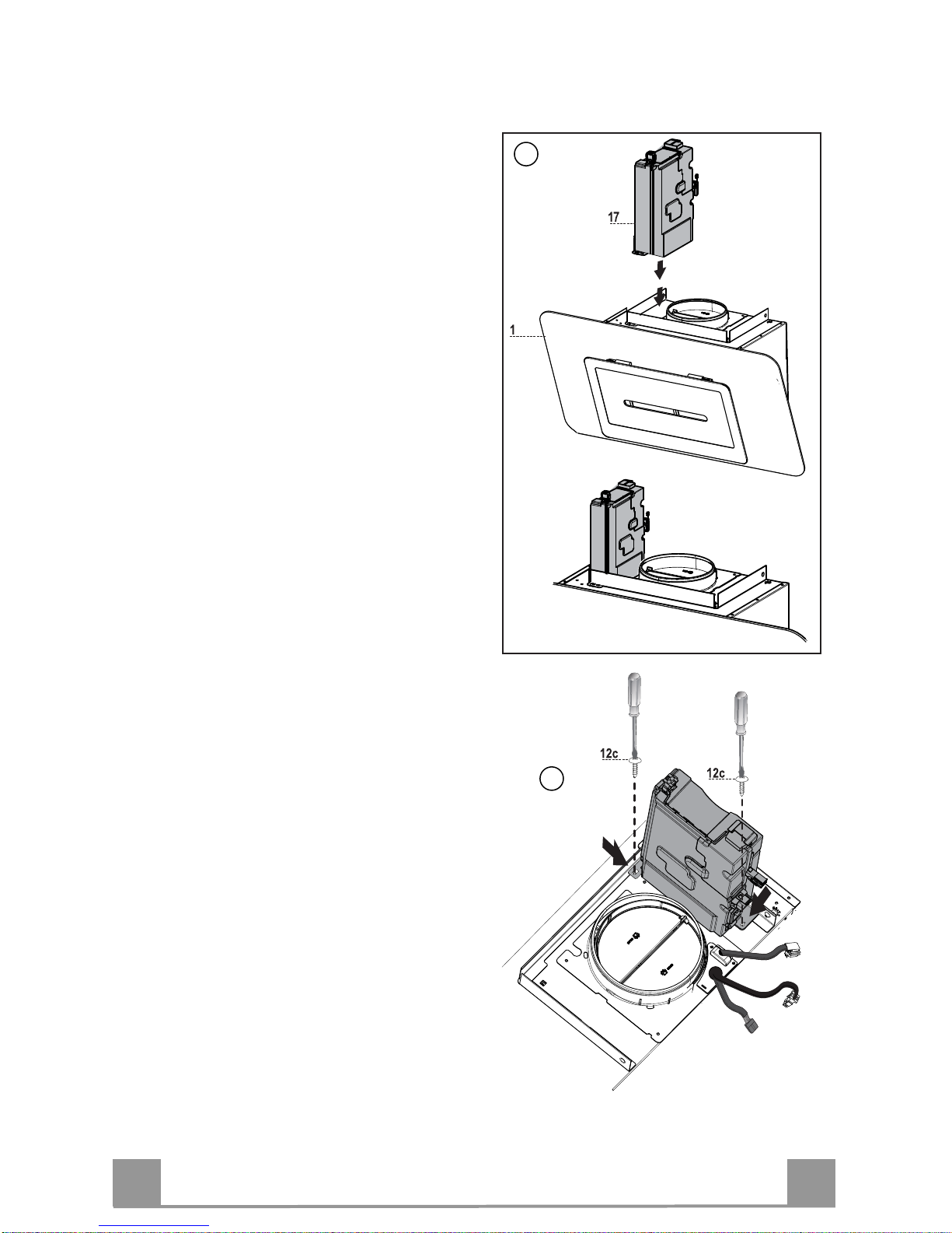
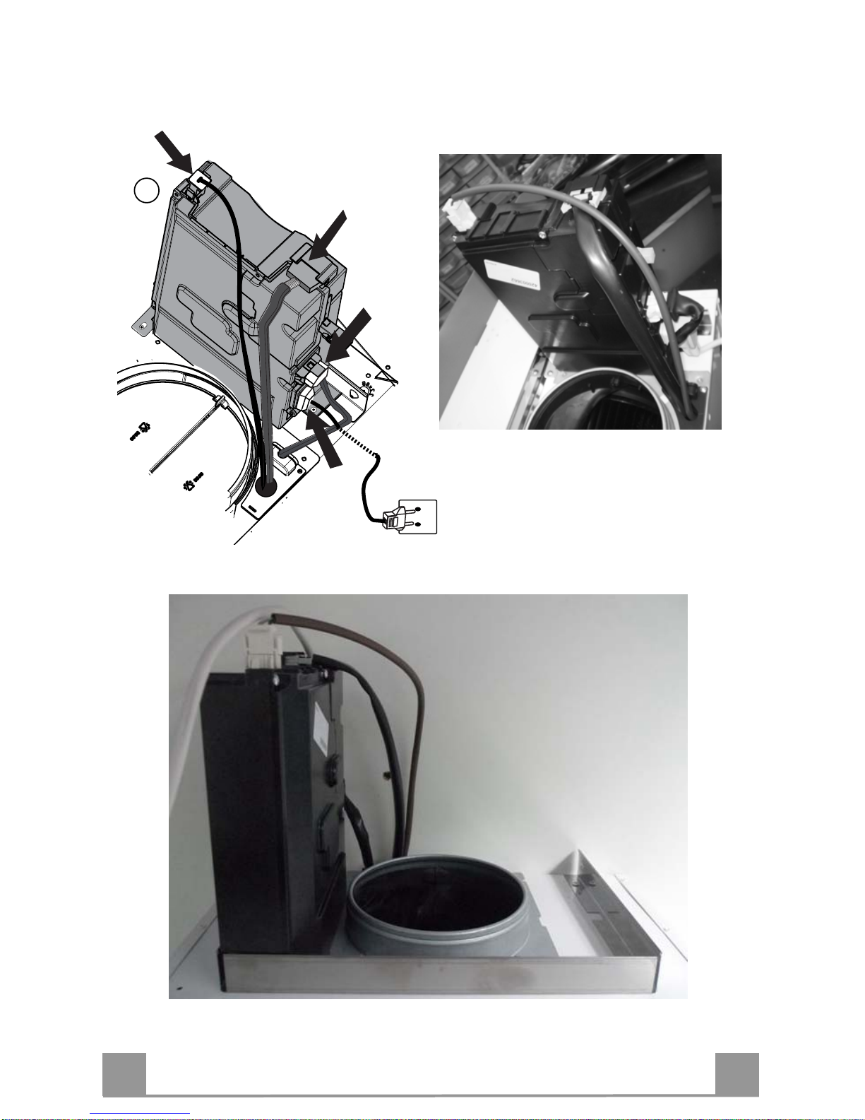
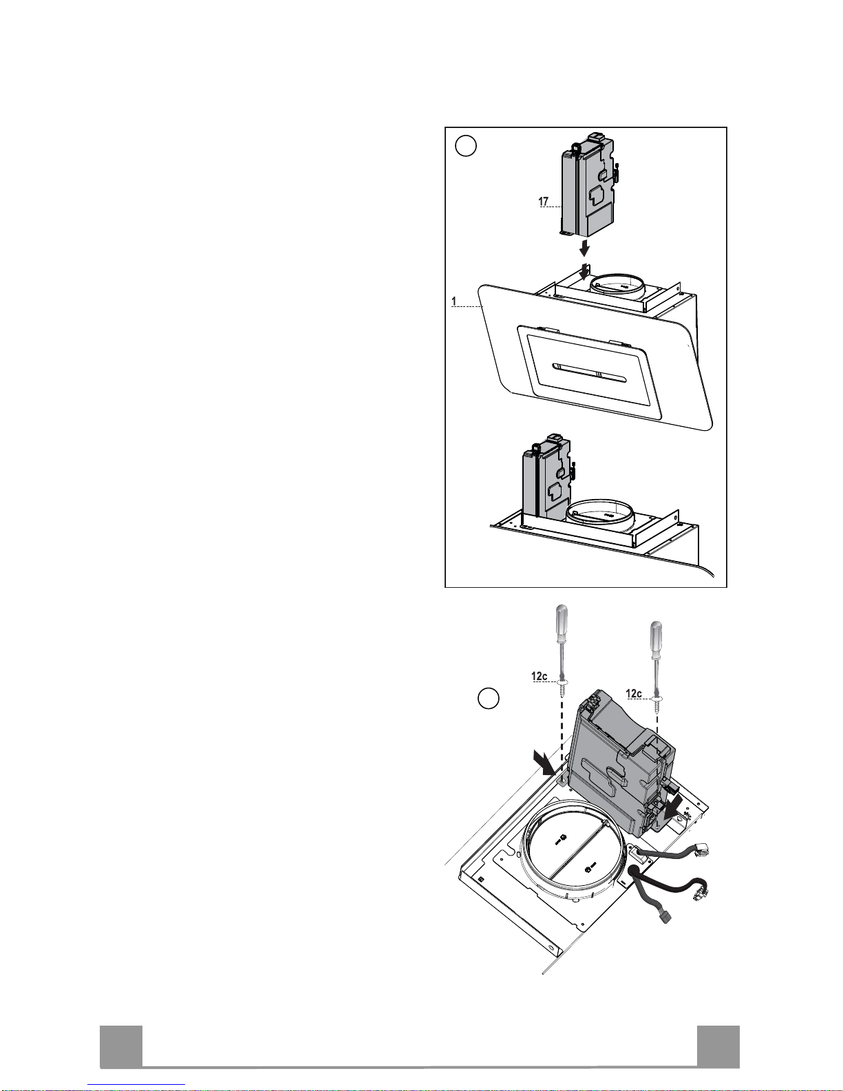
INSTALLATION OF CONTROL BOARD UNIT
1-Rest the control unit 17 on the hood can-
opy 1, positioning the unit so that the
connectors are turned towards the back of
the hood canopy
2-Fix the unit to the hood canopy, using the
2 screws 12c provided
1
2
EN
7
7
3-Make the electrical connections
3
EN
8
8
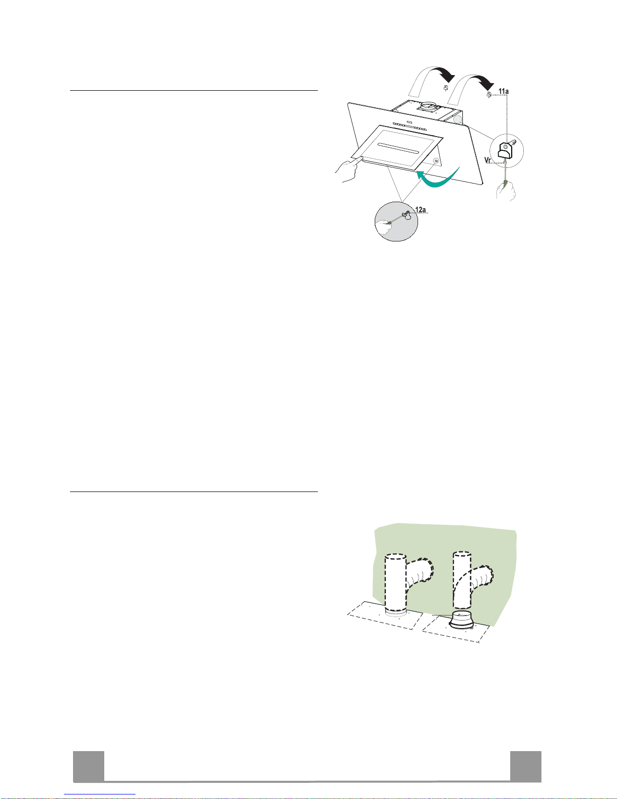
Fitting the hood body
• Open the doors/the door (See section Open
Panels).
• Remove the Metal grease filters using the
handles provided.
• Adjust the two screws Vr, in the brackets 11a,
so that they are at the start of their travel.
• Hook the hood body to the two brackets 11a.
• From the inside of the hood body, turn screws
Vr to level the hood body itself.
• Fasten the safety screw 12a.
• Close the doors/the door again.
Connections
DUCTED VERSION AIR EXHAUST SYSTEM
When installing the ducted version, connect the
hood to the chimney using either a flexible or
rigid pipe ø 150 or 120 mm, the choice of which
is left to the installer.
• To install a ø 120 mm air exhaust connection,
insert the reducer flange 9 on the hood body
outlet.
• Fix the pipe in position using sufficient pipe
clamps (not supplied).
• Remove any activated charcoal filters.
ø 150
9
ø 120
EN
9
9
RECIRCULATION VERSION AIR OUTLET
• Insert the connection extension pieces laterally 14.1 in connection 15.
• Insert the Connector 15 into the Support bracket 7.3 and fix it
with a screw.
• Make sure that the outlet of the extension pieces 14.1 is horizontally and vertically aligned with the chimney outlets.
• Connect the air outlet connection 15 to the hood body outlet
using either a flexible or rigid pipe ø 150 mm, the choice of
which is left to the installer.
• Ensure that the activated charcoal filters have been inserted.
ø 150
15
14.1
7.3
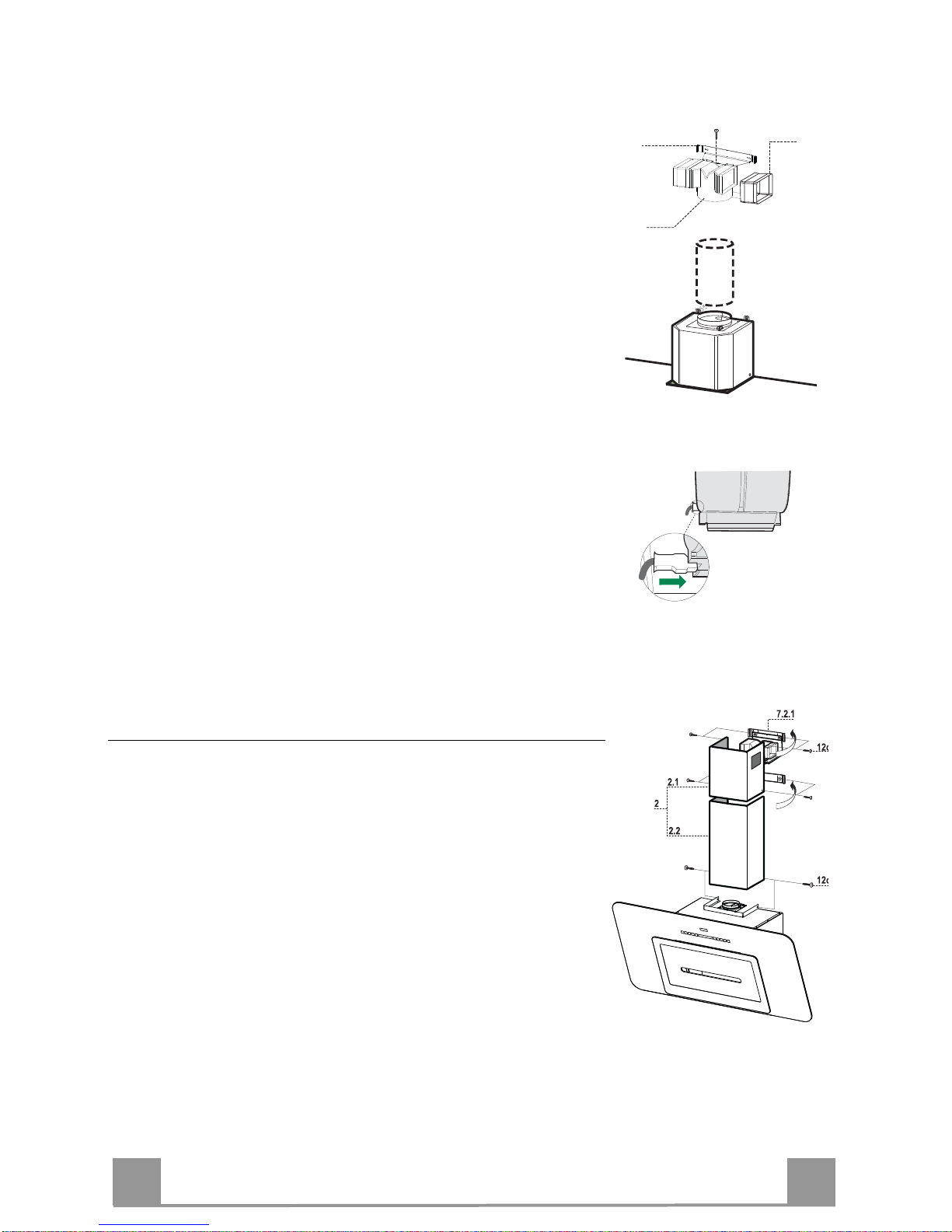
ELECTRICAL CONNECTION
• Connect the hood to the mains through a two-pole switch having a contact gap of at least 3 mm.
• Remove the grease filters (see paragraph Maintenance) being
sure that the connector of the feeding cable is correctly inserted
in the socket placed on the side of the fan.
Flue assembly
Upper exhaust flue
• Slightly widen the two sides of the upper flue and hook them
behind the brackets 7.2.1, making sure that they are well
seated.
• Secure the sides to the brackets by using the 4 screws 12c (2,9
x 9,5) supplied.
• Make sure that the outlet of the extensions pieces is aligned
with the chimney outlets.
Lower exhaust flue
• Slightly widen the two sides of the flue and hook them between the upper flue and the wall, making sure that they are
well seated.
• Fix the lower part laterally to the hood body by using the 2
screws 12c (2,9 x 9,5) supplied.
EN
1
10
USE
Control panel
Button Function Display
A Turns the suction motor on and off. -
B Decreases the working speed. The number of lighted segments decreases.
C Increases the working speed. The number of lighted segments increases.
D Activates Intensive speed from any other speed,
with the exception of Delay and 24H. This speed
is set to operate for 10 minutes, after which the
system returns to the speed that was set before.
Suitable to deal with maximum levels of cooking
fumes.
The indicator
I flashes and all the segments on the
Display are lit.
It is disabled by pressing the Button.
Pressing and holding the button for approximately
5 seconds, with all functions turned off
(Motor+Light), Enables / Disables the Activated
Charcoal Filter alarm.
2 Flashes of symbol C – Alarm Enabled.
1 Flash of symbol C – Alarm Disabled.
E Starts the Motor in Air Change mode, at a speed
that allows suction 10 minutes for hour, after
which the Motor will stop.
Displays
24 and the segments on the Display all light
up and then turn off one at a time in cycle.
It is disabled by pressing the Button.
F Activates automatic switch-off with a 30’ delay.
Suitable to complete elimination of residual
odours. Can only be activated with the motor
turned on at a Speed other than 24H and Intensive.
Displays a flashing
Clock symbol.
It is disabled by pressing the Button.
Press and hold the button for approximately 5
seconds to Enable / Disable the Remote control.
2 Flashes of the Horizontal Bars – Remote Control
Enabled.
1 Flash of the Horizontal Bars – Remote Control
Disabled.
G Performs a Reset of the Filter saturation alarm
when the Button is pressed for approximately 3
seconds.
After 100 hours in operation the
Drop symbol is
displayed to indicate saturation of the Metal Grease
Filters.
After 200 hours in operation the letter
C is displayed
to indicate saturation of the Activated Charcoal
filters.
H Decreases the intensity of the Lighting each time
the Button is pressed, in cycle.
I Turns the lighting system on and off at maximum
intensity.
L Increases the intensity of the Lighting each time
the Button is pressed, in cycle.
Keyboard Lock: it is possible to lock the keyboard, for example when cleaning the Glass surface, when the
Hood has Motor and Lights turned off.
Press A for approximately 5 Seconds to enable or disable the Keyboard Lock, which is always confirmed
by a Beep and an animation on the display motor bar.
B
A
D
C
E
G
F
I
H
L
B
A
D
C
E
G
F
I
H
L
EN
1
11
MAINTENANCE
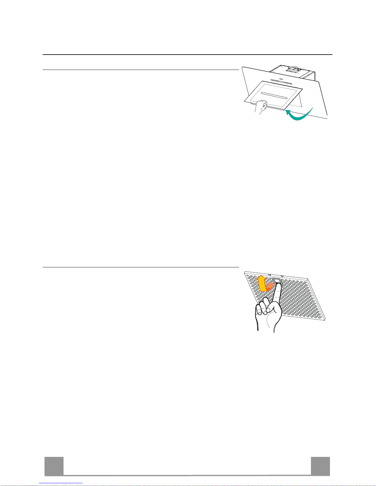
Opening Panel
• Open the Panel by pulling it.
• The panel can be locked in any position.
• Clean the outside with a damp cloth and neutral detergent.
• Clean the inside using a damp cloth and neutral detergent; do
not use wet cloths or sponges, or jets of water; do not use
abrasive substances.
Metal grease filters
Metal filters can be washed also in a dish machine. They need to
be washed every time a drop-symbol appears in the display or at
least every two months. In case of very frequent use these have to
be washed even more often.
Alarm reset
• Press the G-key for at least 2 seconds.
Cleaning
• Pull the comfort panels to open them.
• Remove the filters one at a time holding them up with one
hand and pulling the handle downwards with the other hand at
the same time.
• Wash the filters. Pay attention not to bend them. Make sure
that filters are completely dry before putting them into their
seat. (a possible modification of the filter surface doesn’t influence its efficiency).
• Place the filters again into their seats and make sure that the
handle of the filter remains outside.
• Close the comfort panel.
EN
1
12
Charcoal filter (recycling version)
This filter cannot be washed or regenerated. It must be replaced when the C appears on the
display or at least once every 4 months. The filter saturation alarm has to be activated already
before.
Activation of the alarm signal
• In the recycling version hoods the filter saturation alarm must be activated during the installation or later.
• Switch off the hood and the lights.
• Press the D-key for about 5 seconds.
• 2 flash C-symbol lit - charcoal filter saturation alarm ACTIVATED.
• 1 flash C-symbol lit - charcoal filter saturation alarm DEACTIVATED.
CHANGING THE ACTIVATED CHARCOAL FILTER
Resetting the alarm signal
• Turn the Lights and the Suction Motor off.
• Press button G and hold it for at least 2 seconds.
Changing the Filter
• Pull the comfort panels to open them.
• Remove the grid by pulling it from the side.
• Remove the saturated Activated Charcoal Filters, as indicated (A).
• Fit the new Filters, as indicated (B).
• Replace the Grid.
• Close the comfort panel.
A
B
Lighting unit
Warning: This appliance is fitted with a white LED lamp classed
as 1M according to EN 60825-1: 1994 + A1:2002 + A2:2001
standards; maximum optical power emitted @439nm: 7µW. Do
not look directly at the light through optical devices (binoculars,
magnifying glasses…).
• For replacement contact technical support. ("To purchase contact technical support")
IT
1
13
CONSIGLI E SUGGERIMENTI
Questo libretto di istruzioni per l'uso è previsto per più versioni dell' apparecchio. É possibile che siano
descritti singoli particolari della dotazione, che non riguardano il Vostro apparecchio.
INSTALLAZIONE
• Il produttore declina qualsiasi responsabilità per danni dovuti ad installazione non corretta o non conforme
alle regole dell’arte.
• La distanza minima di sicurezza tra il Piano di cottura e la Cappa deve essere di 650 mm, (alcuni modelli
possono essere installati ad un’altezza inferiore, fare riferimento ai paragrafi ingombro e installazione).
• Verificare che la tensione di rete corrisponda a quella riportata nella targhetta posta all’interno della Cappa.
• Per Apparecchi in Classe I
a
accertarsi che l’impianto elettrico domestico garantisca un corretto scarico a
terra.
• Collegare la Cappa all’uscita dell’aria aspirata con tubazione di diametro pari o superiore a 120 mm. Il
percorso della tubazione deve essere il più breve possibile.
• Non collegare la Cappa a condotti di scarico dei fumi prodotti da combustione (caldaie, caminetti, ecc.).
• Nel caso in cui nella stanza vengano utilizzati sia la Cappa che apparecchi non azionati da energia elettrica
(ad esempio apparecchi utilizzatori di gas), si deve provvedere ad una aerazione sufficiente dell’ambiente.
Se la cucina ne fosse sprovvista, praticare un’apertura che comunichi con l’esterno, per garantire il richiamo d’aria pulita. Un uso proprio e senza rischi si ottiene quando la depressione massima del locale non
supera i 0,04 mBar.
• In caso di danneggiamento del cavo alimentazione, esso deve essere sostituito dal costruttore o dal servizio di assistenza tecnica, in modo da prevenire ogni rischio.
• Se le istruzioni di installazione del dispositivo di cottura a gas indicano che è necessaria una distanza
maggiore di quella indicato sopra, è necessario tenerne conto. Bisogna rispettare tutte le normative relative
allo scarico dell’aria.
USO
• La Cappa è stata progettata esclusivamente per uso domestico, per abbattere gli odori della cucina.
• Non fare mai uso improprio della Cappa.
• Non lasciare fiamme libere a forte intensità sotto la Cappa in funzione.
• Regolare sempre le fiamme in modo da evitare una evidente fuoriuscita laterale delle stesse rispetto al
fondo delle pentole.
• Controllare le friggitrici durante l’uso: l’olio surriscaldato potrebbe infiammarsi.
• Non preparare alimenti flambè sotto la cappa da cucina; pericolo d'incendio.
• Questo apparecchio non deve essere utilizzato da persone (bambini inclusi) con ridotte capacità psichiche,
sensoriali o mentali, oppure da persone senza esperienza e conoscenza, a meno che non siano controllati
o istruiti all’uso dell’apparecchio da persone responsabili della loro sicurezza.
• I bambini devono essere supervisionati per assicurarsi che non giochino con l’apparecchio.
• “ATTENZIONE: Le parti accessibili possono diventare molto calde se utilizzate con degli apparecchi di
cottura”.
MANUTENZIONE
• Prima di procedere a qualsiasi operazione di manutenzione, disinserire la Cappa togliendo la spina elettrica o spegnendo l’interruttore generale.
• Effettuare una scrupolosa e tempestiva manutenzione dei Filtri secondo gli intervalli consigliati (Rischio di
incendio).
• Per la pulizia delle superfici della Cappa è sufficiente utilizzare un panno umido e detersivo liquido neutro.
Il simbolo sul prodotto o sulla confezione indica che il prodotto non deve essere considerato come un normale
rifiuto domestico, ma deve essere portato nel punto di raccolta appropriato per il riciclaggio di apparecchiature elettriche
ed elettroniche. Provvedendo a smaltire questo prodotto in modo appropriato, si contribuisce a evitare potenziali conseguenze negative per l’ambiente e per la salute, che potrebbero derivare da uno smaltimento inadeguato del prodotto.
Per informazioni più dettagliate sul riciclaggio di questo prodotto, contattare l’ufficio comunale, il servizio locale di smaltimento rifiuti o il negozio in cui è stato acquist ato il prodotto.
2°
IT
1
14
CARATTERISTICHE
Ingombro
898
300
520
41.5
81
19.2 126
Min.625 - Max.980
380
500
330
35
357
160
500
300
200
R
5
400
100
Componenti
Rif. Q.tà Componenti di Prodotto
1 1 Corpo Cappa completo di: Comandi, Luce, Gruppo
Ventilatore, Filtri
2.1 1 Camino Superiore
2.2 1 Camino Inferiore
9 1 Flangia riduzione 150-120
14.1 2 Prolunga Raccordo Uscita Aria
15 1 Raccordo Uscita Aria
17 1 Gruppo Controlli
Rif. Q.tà Componenti di Installazione
7.2.1 2 Staffe Fissaggio Camino Superiore
7.3 1 Staffa Sostegno Raccordo
11 6 Tasselli
11a 2 Tasselli SB 12/10
12a 6 Viti 4,2 x 44,4
12c 8 Viti 2,9 x 6,5
Q.tà Documentazione
1 Libretto Istruzioni
IT
1
15
INSTALLAZIONE
Foratura Parete e Fissaggio Staffe
Tracciare sulla Parete:
• una linea Verticale fino al soffitto o al limite superiore, al centro della zona prevista per il montaggio
della Cappa;
• una linea Orizzontale a 788 mm min. sopra il Piano di Cottura.
• Segnare un punto (1) sulla linea orizzontale a 164 mm alla destra della linea verticale di riferimento.
• Ripetere questa operazione dalla parte opposta, verificandone il livellamento.
• Segnare come indicato, un punto di riferimento (2) a 140 mm dalla linea Verticale di riferimento, e
540 mm sopra il Piano di Cottura.
• Ripetere questa operazione dalla parte opposta, verificandone il livellamento.
• Forare ø 12 mm i punti (1) segnati.
• Forare ø 8 mm i punti (2) segnati.
• Inserire i tasselli con staffa 11a nei fori (1) e avvitare.
• Inserire il tassello 11 nei fori (2).
• Appoggiare come indicato la Staffa 7.2.1 a 1-2 mm dal soffitto o dal limite superiore, allineando il
suo centro (intagli) sulla linea Verticale di riferimento.
• Segnare i centri dei Fori della Staffa.
• Appoggiare come indicato la Staffa 7.2.1 a X mm sotto la prima staffa (X = altezza Camino Superio-
re in dotazione), allineando il suo centro (intagli) sulla linea Verticale di riferimento.
• Segnare i centri dei Fori della Staffa.
• Forare ø 8 mm i punti segnati.
• Inserire i tasselli 11 nei fori.
• Fissare la Staffa inferiore 7.2.1 utilizzando le Viti 12a (4,2 x 44,4 ) in dotazione.
• Fissare insieme la Staffa superiore 7.2.1 e la Staffa sostegno raccordo 7.3 utilizzando le 2 viti 12a
(4,2 x 44,4) in dotazione.
IT
1
16
INSTALLAZIONE GRUPPO CONTROLLI
1-Appoggiare il gruppo controlli 17 al cor-
po cappa 1, posizionando il gruppo in
modo che i connettori siano rivolti verso
il lato posteriore del corpo cappa
2-Fissare il gruppo al corpo cappa, utiliz-
zando le 2 viti 12c in dotazione
1
2
IT
1
17
3-Effettuare le connessioni elettriche
3
 Loading...