

Page 1

Instructions for use and installation
Cooker Hood
Istruzioni per l’uso e l’installazione
Cappa
Mode d’emploi et installation
Hotte de Cuisine
Bedienungsanleitung und Installation
Dunstabzugshaube
Kullan
ım ve montaj talimatları
Davlumbaz
FDW 908 RB XS
GB
IT
FR
DE
TR
Page 2

2
2
INDEX
RECOMMENDATIONS AND SUGGESTIONS ..................................................................................................................... 3
CHARACTERISTICS ............................................................................................................................................................. 6
INSTALLATION ...................................................................................................................................................................... 8
USE ...................................................................................................................................................................................... 18
MAINTENANCE ................................................................................................................................................................... 20
INDICE
CONSIGLI E SUGGERIMENTI ............................................................................................................................................ 21
CARATTERISTICHE ............................................................................................................................................................ 24
INSTALLAZIONE ................................................................................................................................................................. 26
USO ...................................................................................................................................................................................... 36
MANUTENZIONE................................................................................................................................................................. 38
SOMMAIRE
CONSEILS ET SUGGESTIONS .......................................................................................................................................... 39
CARACTERISTIQUES ......................................................................................................................................................... 42
INSTALLATION .................................................................................................................................................................... 44
UTILISATION ....................................................................................................................................................................... 54
ENTRETIEN ......................................................................................................................................................................... 56
INHALTSVERZEICHNIS
EMPFEHLUNGEN UND HINWEISE ................................................................................................................................... 57
CHARAKTERISTIKEN ......................................................................................................................................................... 60
MONTAGE ........................................................................................................................................................................... 62
BEDIENUNG ........................................................................................................................................................................ 72
WARTUNG ........................................................................................................................................................................... 74
IÇERIKLER
TAVSIYELER VE ÖNERILER .............................................................................................................................................. 75
ÖZELLIKLER ........................................................................................................................................................................ 78
MONTAJ ............................................................................................................................................................................... 80
KULLANIM ........................................................................................................................................................................... 90
BAKIM .................................................................................................................................................................................. 92
EN
IT
FR
DE
TR
Page 3
EN
3
3
RECOMMENDATIONS AND SUGGESTIONS
The Instructions for Use apply to several versions of this appliance.
Accordingly, you may find descriptions of individual features that do not
apply to your specific appliance.
INSTALLATION
•
The manufacturer will not be held liable for any damages resulting from
incorrect or improper installation.
• The minimum safety distance between the cooker top
and the extractor hood is 650 mm (some models can
be installed at a lower height, please refer to the
paragraphs on working dimensions and installation).
• Check that the mains voltage corresponds to that
indicated on the rating plate fixed to the inside of the
hood.
• For Class I appliances, check that the domestic
power supply guarantees adequate earthing.
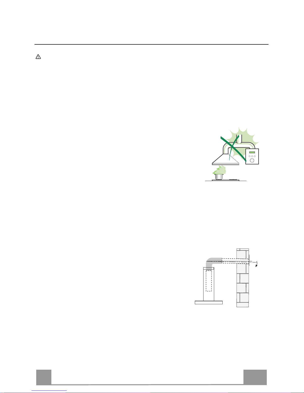
Connect the extractor to the exhaust flue through a pipe of minimum
diameter 120 mm. The route of the flue must be as short as possible.
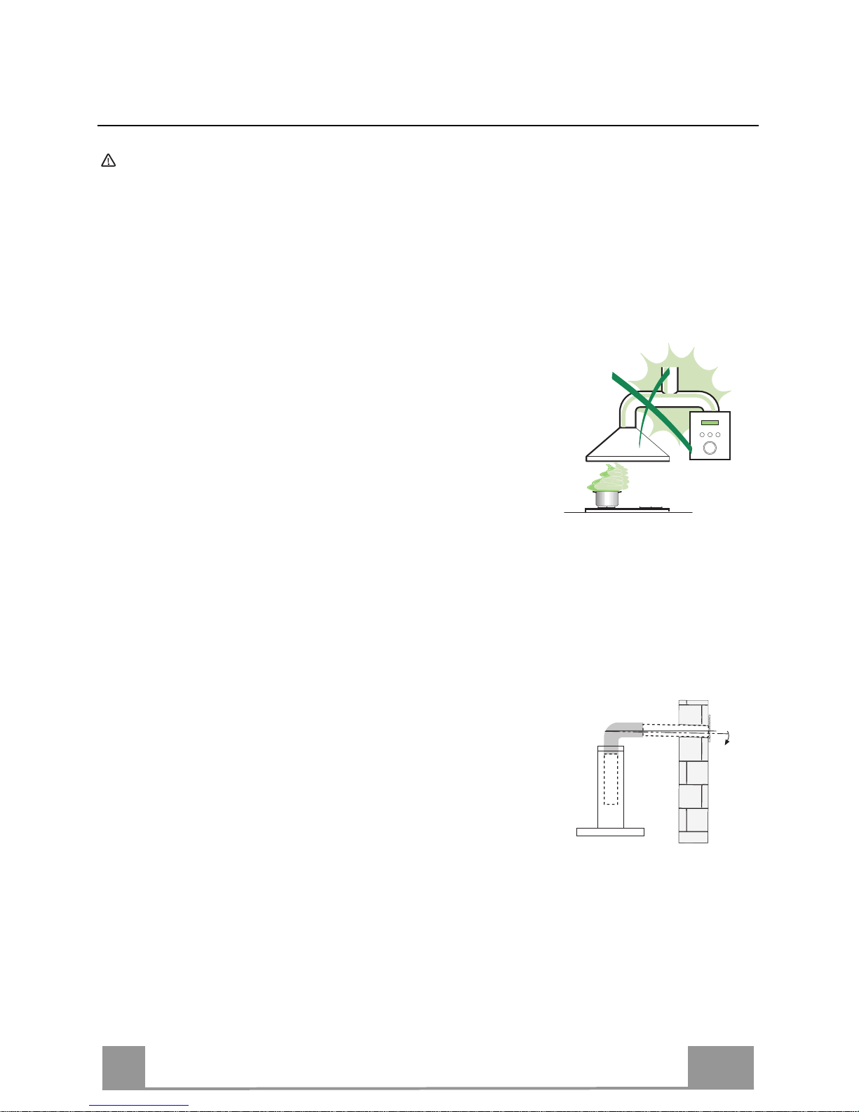
• Do not connect the extractor hood to exhaust ducts carrying combustion
fumes (boilers, fireplaces, etc.).
• If the extractor is used in conjunction with nonelectrical appliances (e.g. gas burning
appliances), a sufficient degree of aeration must
be guaranteed in the room in order to prevent the
backflow of exhaust gas. The kitchen must have
an opening communicating directly with the open
air in order to guarantee the entry of clean air.
When the cooker hood is used in conjunction with
appliances supplied with energy other than electric, the negative pressure in
the room must not exceed 0,04 mbar to prevent fumes being drawn back
into the room by the cooker hood.
• In the event of damage to the power cable, it must be replaced by the
manufacturer or by the technical service department, in order to prevent any
risks.
2°
Page 4
EN
4
4
• If the instructions for installation for the gas hob specify a greater distance
specified above, this has to be taken into account. Regulations concerning
the discharge of air have to be fulfilled.
• Use only screws and small parts in support of the hood.
Warning: Failure to install the screws or fixing device in accordance with
these instructions may result in electrical hazards.
• Connect the hood to the mains through a two-pole switch having a contact
gap of at least 3 mm.
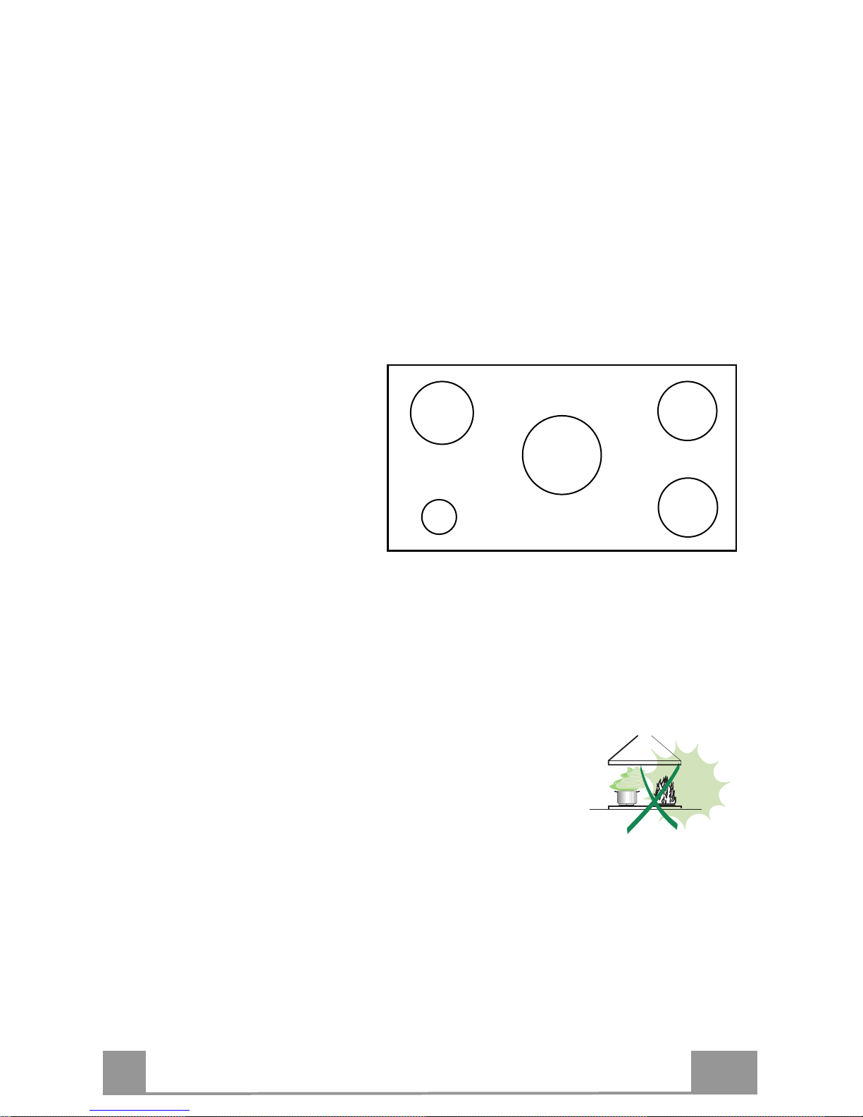
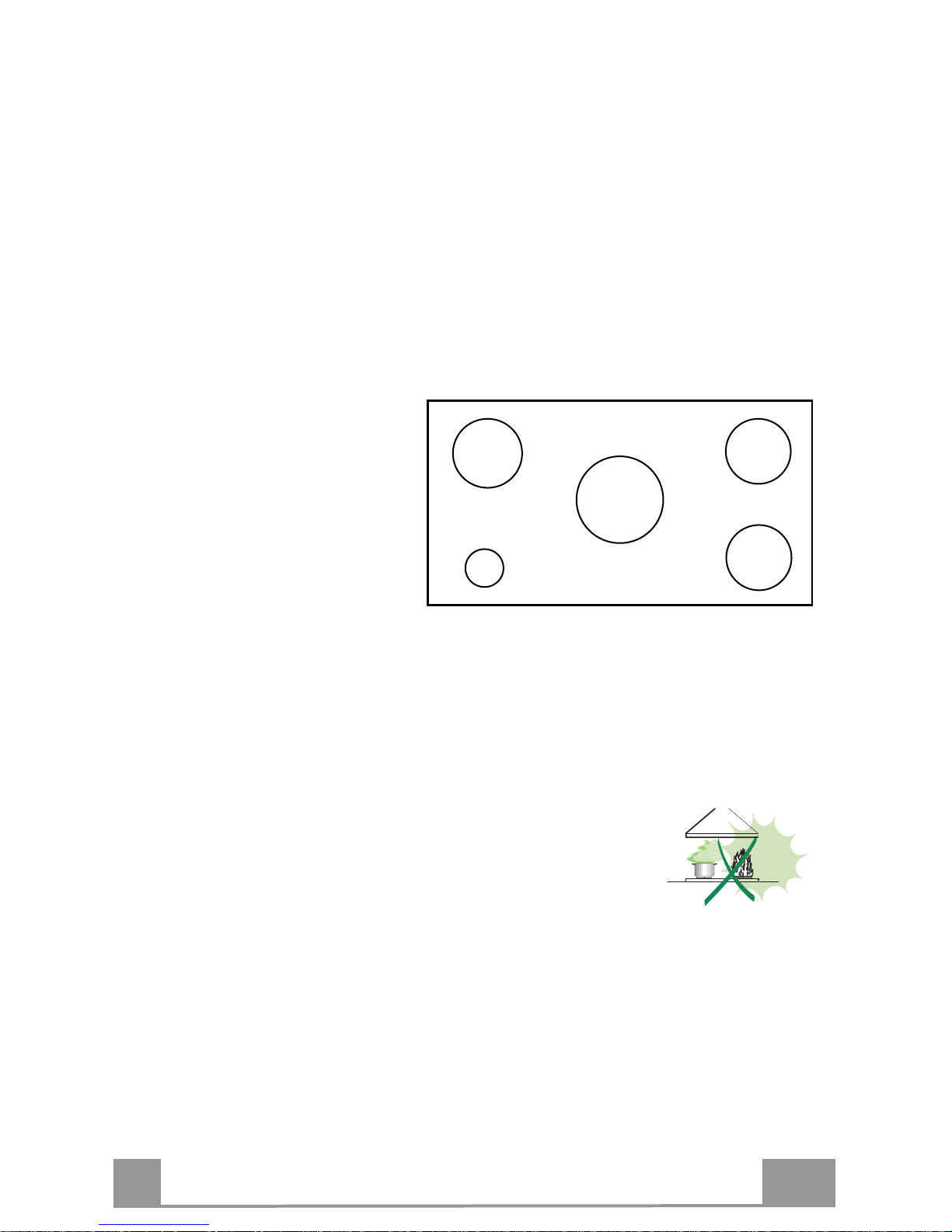
• This Cooker hood can be used in conjunction with a Gas Cook Top having
the following characteristics:
• Maximum power 12,4 kW
• 5 fire like the picture
USE
•
The extractor hood has been designed exclusively for domestic use to
eliminate kitchen smells.
• Never use the hood for purposes other than for which it has been designed.
• Never leave high naked flames under the hood when it is in operation.
• Adjust the flame intensity to direct it onto the bottom of the pan only, making
sure that it does not engulf the sides.
• Deep fat fryers must be continuously monitored
during use: overheated oil can burst into flames.
• Do not flambè under the range hood; risk of fire.
• This appliance can be used by children aged from 8
years and above and persons with reduced physical,
sensory or mental capabilities or lack of experience and knowledge if they
have been given supervision or instruction concerning use of the appliance
in a safe way and understand the hazards involved. Children shall not play
with the appliance. Cleaning and user maintenance shall not be made by
children without supervision.
2,6 kW
5 kW
1,9 kW
1,9 kW
1 kW
Page 5

EN
5
5
• “ CAUTION: Accessible parts may become hot when used with cooking
appliances.”.
MAINTENANCE
•
Switch off or unplug the appliance from the mains supply before carrying out
any maintenance work.
• Clean and/or replace the Filters after the specified time period (Fire hazard).
• The Grease filters must be cleaned every 2 months of operation, or more
frequently for particularly heavy usage, and can be washed in a dishwasher.
• The Activated charcoal filter is not washable and cannot be regenerated,
and must be replaced approximately every 4 months of operation, or more
frequently for particularly heavy usage.
• Clean the hood using a damp cloth and a neutral liquid detergent.
The symbol on the product or on its packaging indicates that this product
may not be treated as household waste. Instead it shall be handed over to the
applicable collection point for the recycling of electrical and electronic
equipment. By ensuring this product is disposed of correctly, you will help
prevent potential negative consequences for the environment and human
health, which could otherwise be caused by inappropriate waste handling of
this product. For more detailed information about recycling of this product,
please contact your local city office, your household waste disposal service or
the shop where you purchased the product.
Page 6
EN
6
6
CHARACTERISTICS
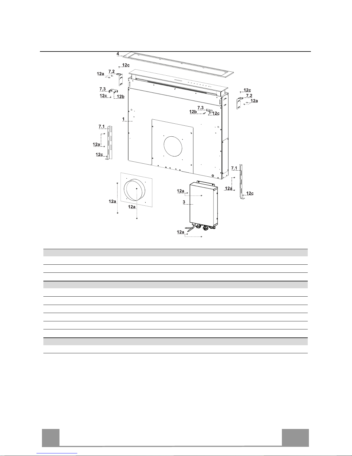
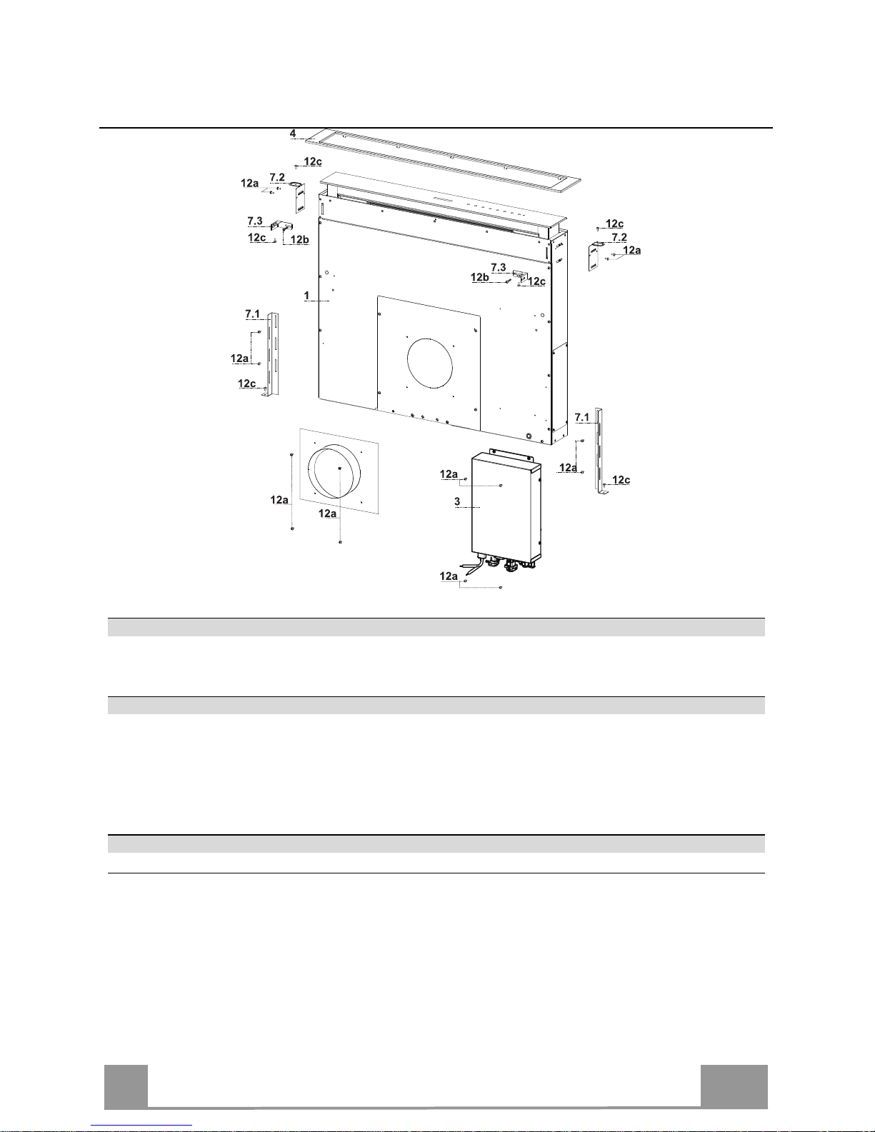
Components
Ref. Q.ty Product Components
1 1 Hood Canopy complete with: Controls, Light, Filters
3 1 Electric unit
4 1 Front Frame
Ref. Q.ty Installation Components
7.1 2 Splashback Fixing Bracket
7.2 2 Hob Fixing Bracket
7.3 2 Side Bracket
12a 16 Screws 3.5 x 9.5
12b 2 Screws M4 x 8
12c 6 Screws 4 x 15
Q.ty Documentation
1 Instruction Manual
Page 7
EN
7
7
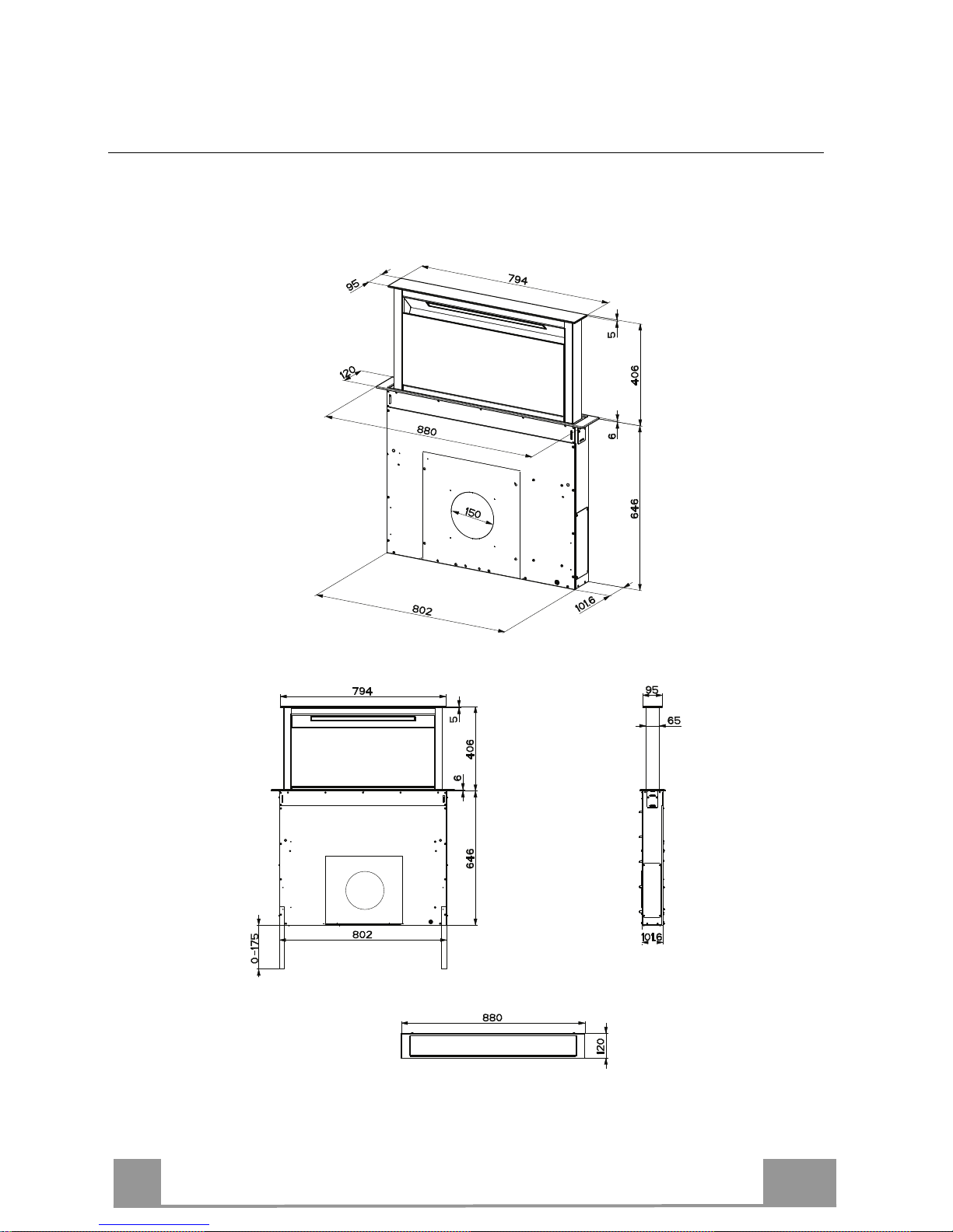
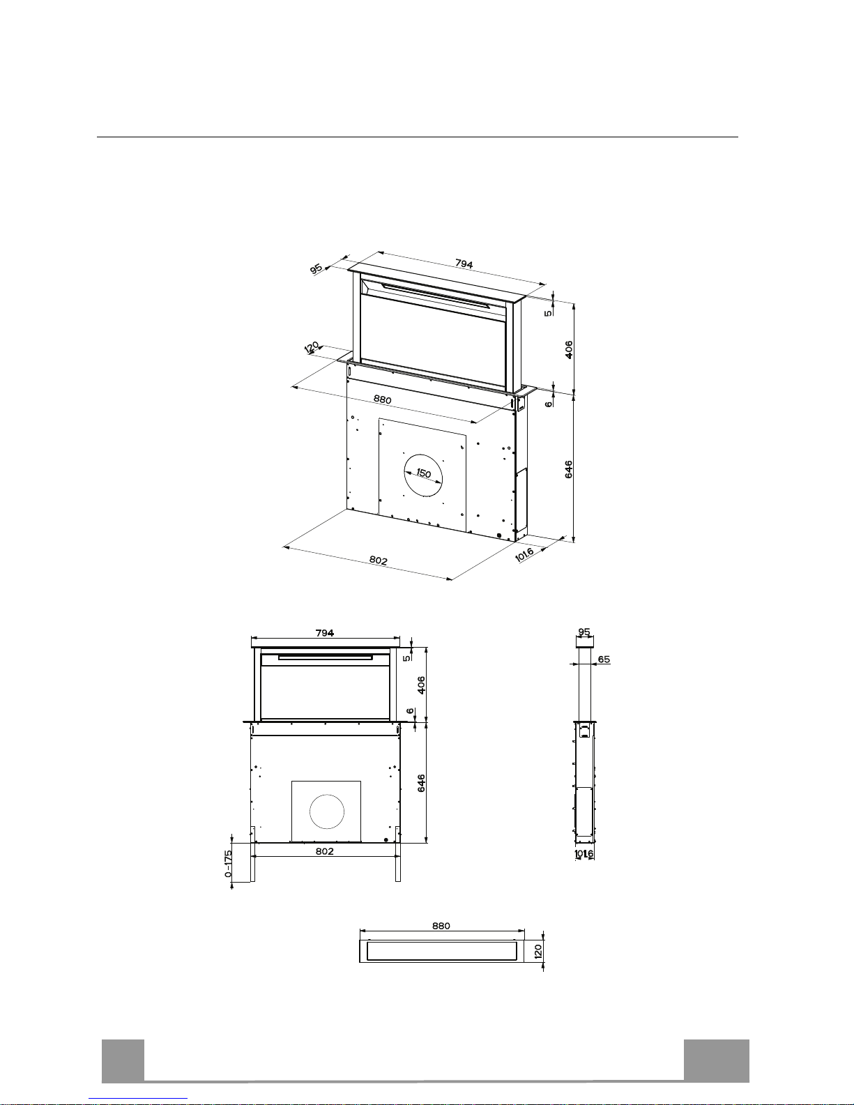
Dimensions
Page 8
EN
8
8
INSTALLATION
This Hood is set up to be fitted inside the kitchen unit in:
• Ducting version: Evacuation to the outside.
• Recirculation version: Internal recirculation.
Sequence of operations - Installation
• Drilling the Support Surface and Fitting the Hood
• Connections
• Functional Check
• Disposal of Packaging
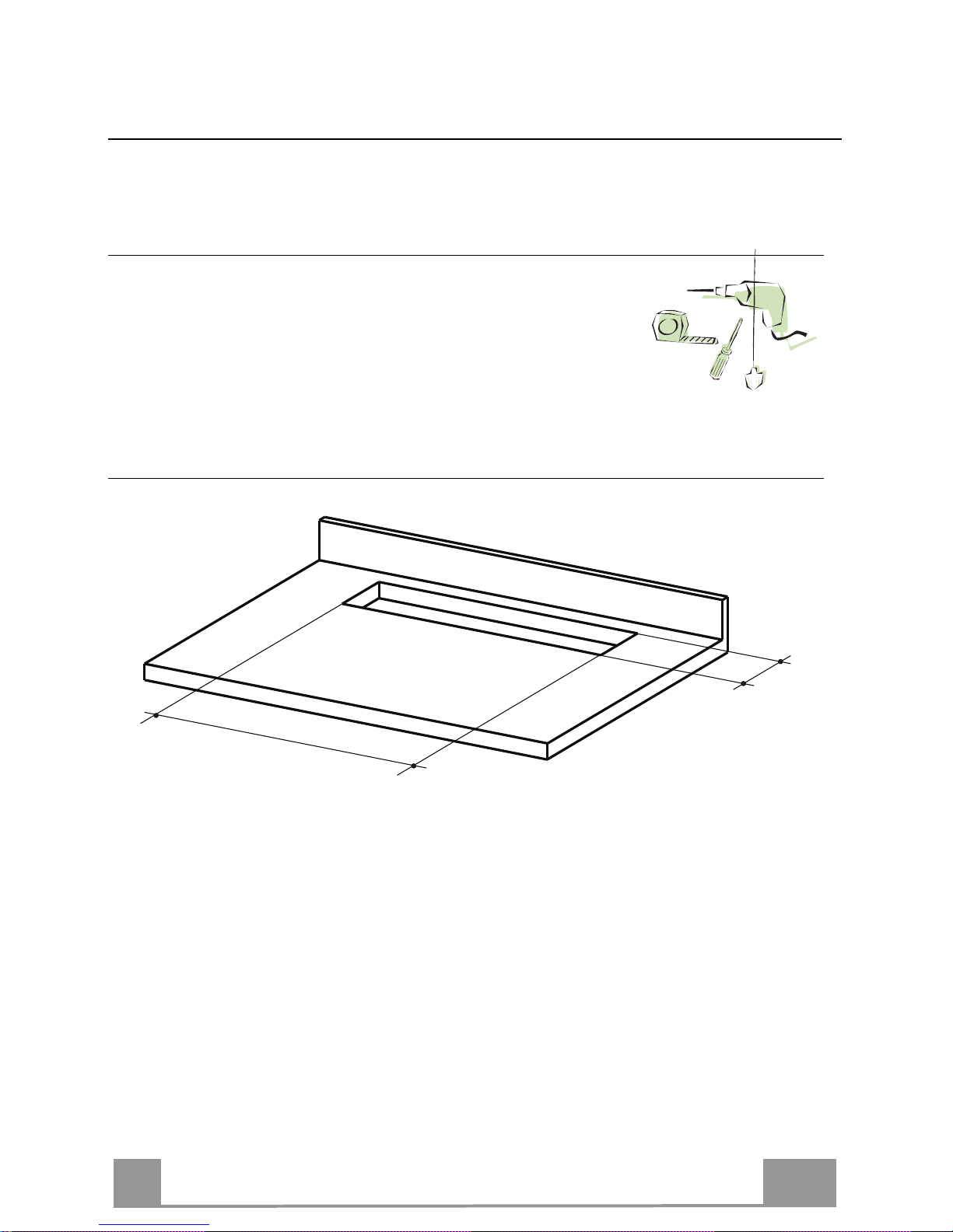
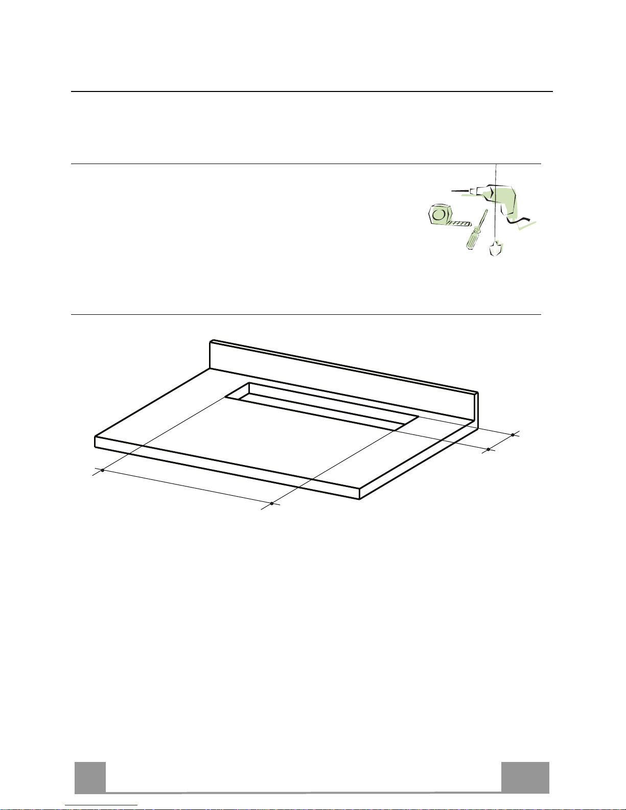
Drilling the Support Surface
X
812
Warning
Once the Support surface has been drilled the Hood Canopy can be installed in two ways:
• By inserting the Hood Canopy from below ( X = 106 mm ).
• By inserting the Hood Canopy from above ( X = 113 mm ).
IMPORTANT
The minimum distance between the opening for the hob and the one for the hood must be of at
least 3-5 cm according to the strength of the material used for the working top.
Page 9
EN
9
9
7.2
12a
7.2
12a
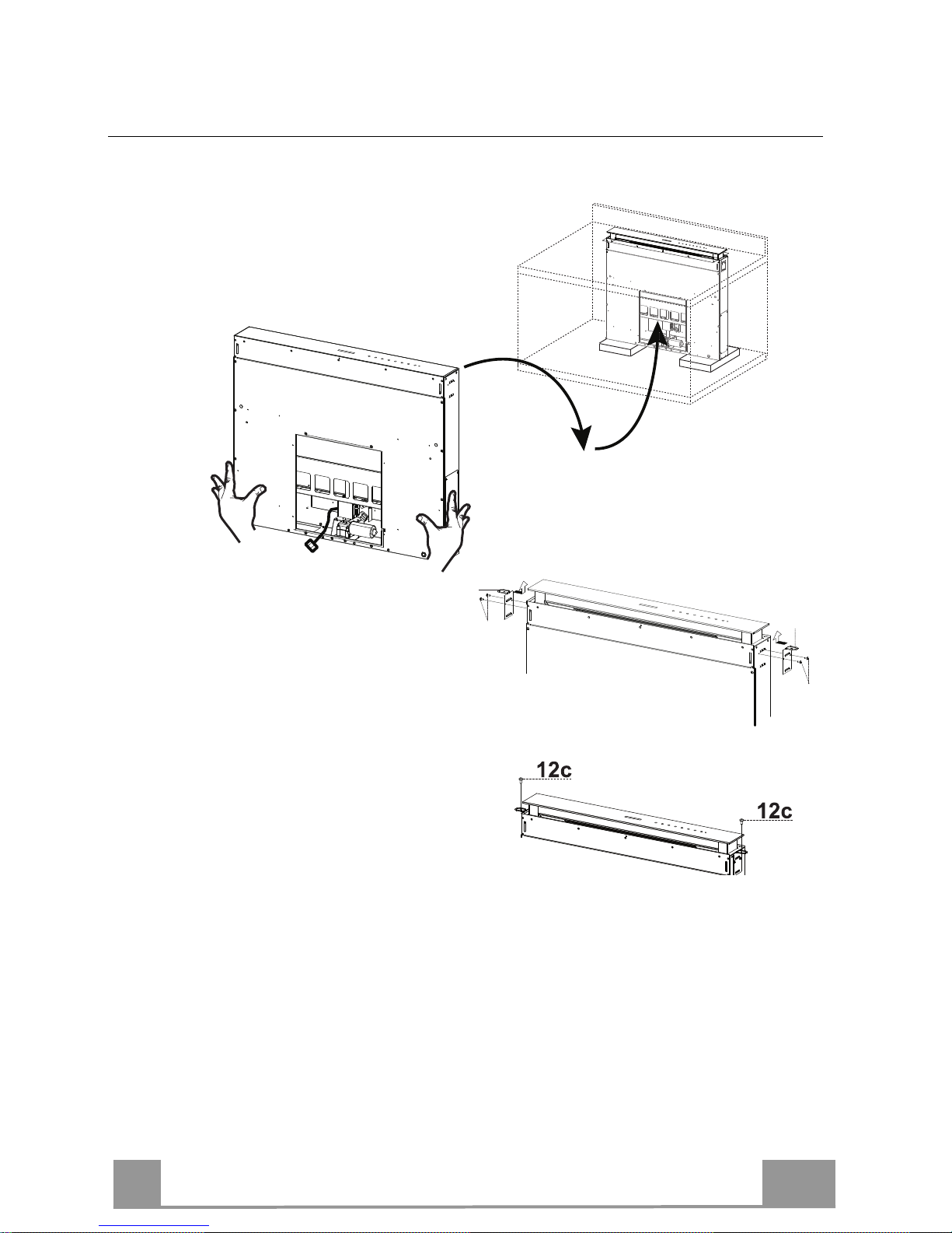
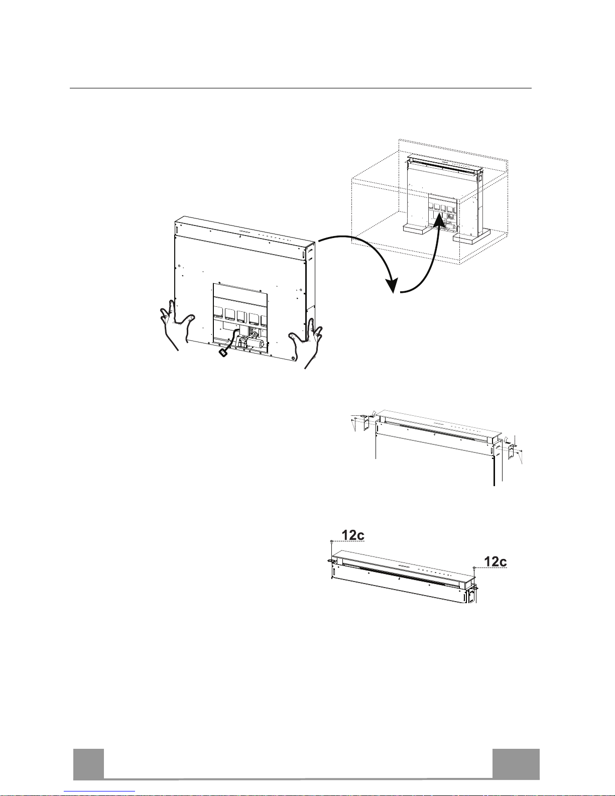
Inserting the Hood Canopy into the support surface from below
• Insert the Hood Canopy from below into the
support worktop, drilled as described above.
• With the aid of a
support, lift the Hood
Canopy until the front
comes out of the
Worktop.
• Insert the Brackets 7.2, as indicated in the
figure, into the slots provided and fix them
with the screws 12a provided.
• Centre the Hood Canopy with respect to the
Cooking Hob slot.
• Using the 2 screws 12c provided, fix the
Hood Canopy to the worktop and remove
the supports.
Warning:
If the cooker top is made from a material that does not allow the screws 12c to be inserted, use
a small amount of silicone to glue the Brackets 7.2 to the top and allow it to dry completely
before proceeding with installation.
Page 10

EN
1
10
7.2
12a
7.2
12a
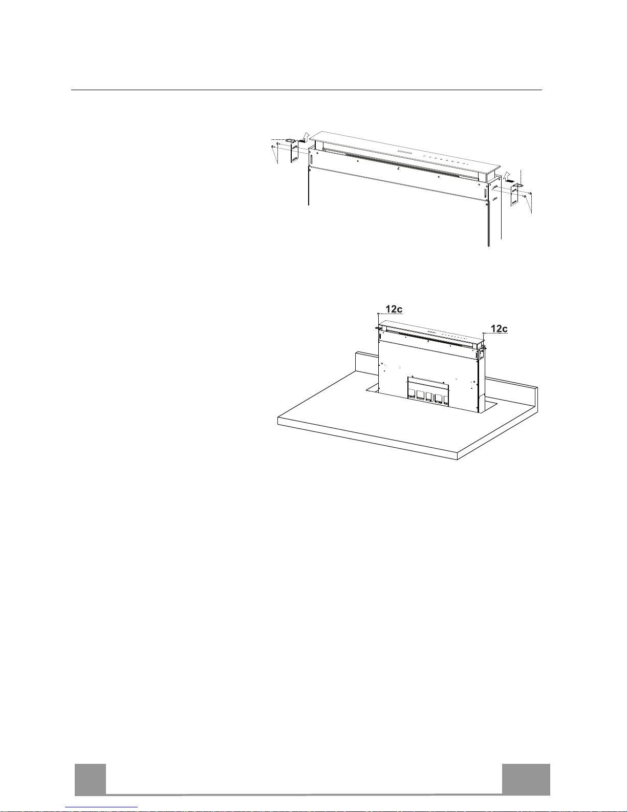
Inserting the Hood Canopy into the support surface from above
• Insert the Brackets 7.2, as
indicated in the figure, into the
slots provided and fix them with
the screws 12a provided.
• Insert the Hood Canopy into the
cooker top, drilled as described
above.
• Centre the Hood Canopy with
respect to the Cooking Hob slot.
• Fix the Hood Canopy with the 2
screws 12c provided.
Warning:
If the cooker top is made from a material that does not allow the screws 12c to be inserted, use
a small amount of silicone to glue the Brackets 7.2 to the top and allow it to dry completely
before proceeding with installation.
Page 11
EN
1
11
12c
12a
7.1
12a
7.1
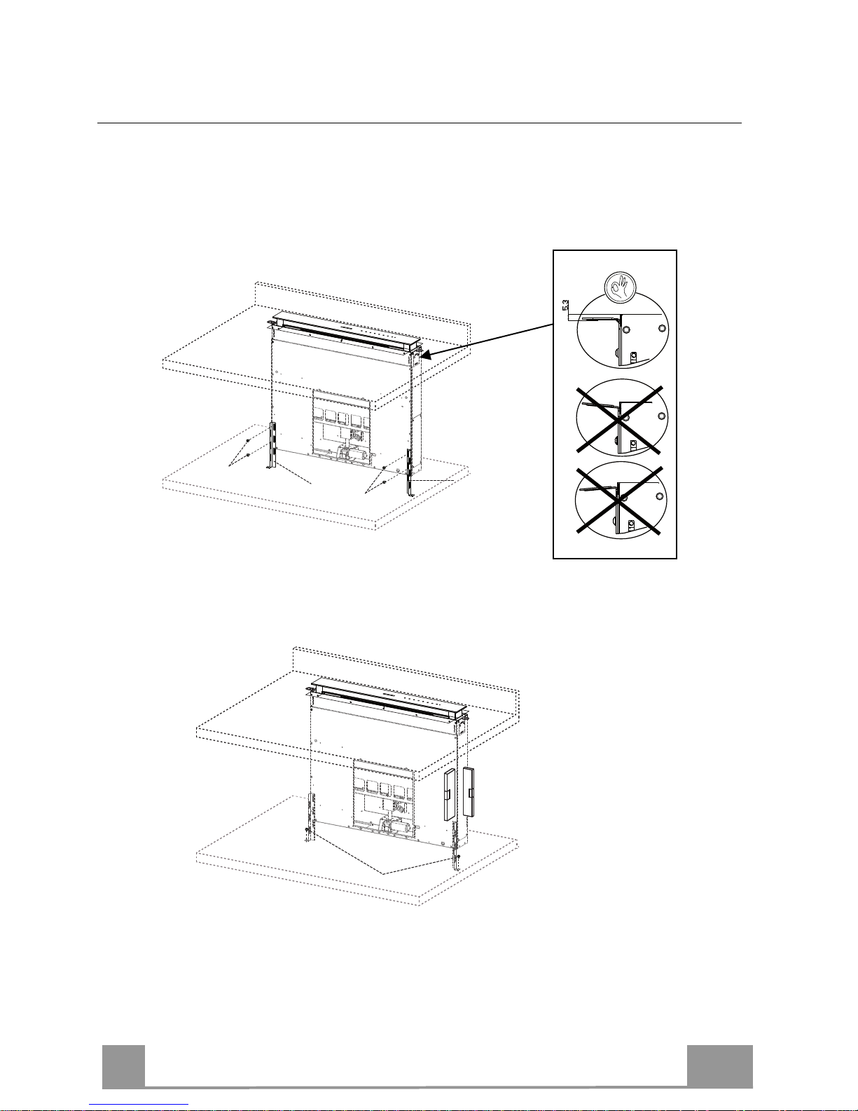
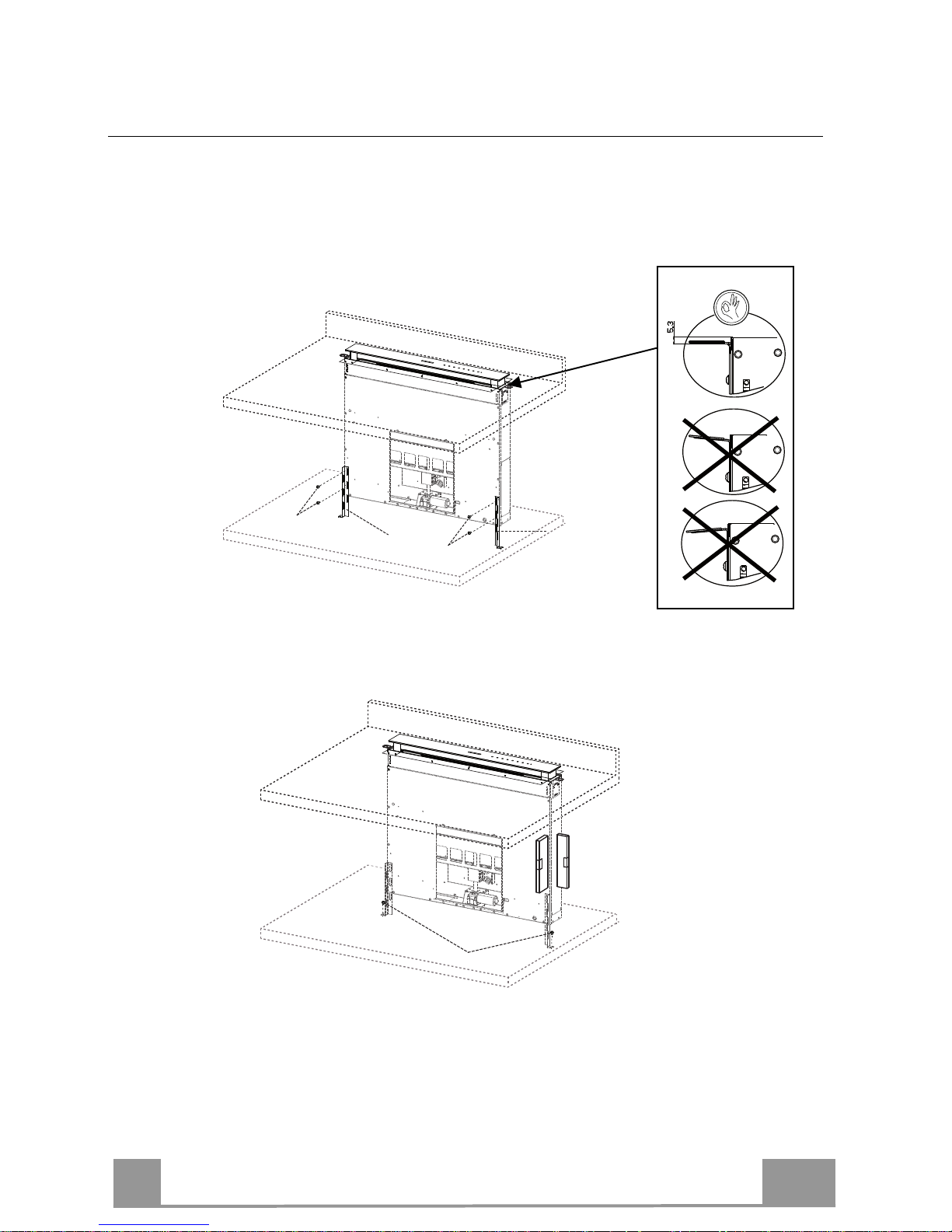
Fixing the Lower Brackets
• Screw the brackets 7.1 to the front of the Hood Canopy using the screws 12a provided.
• Before tightening the Brackets completely, make all the adjustments to allow them to rest on
the lower base of the worktop to avoid deformation of the upper brackets 7.2 as shown in the
figure.
• With the aid of a spirit level, set the Hood Canopy level vertically and fix it to the Lower
Surface using 2 screws 12c provided.
• Tighten the screws 12a completely.
Page 12
EN
1
12
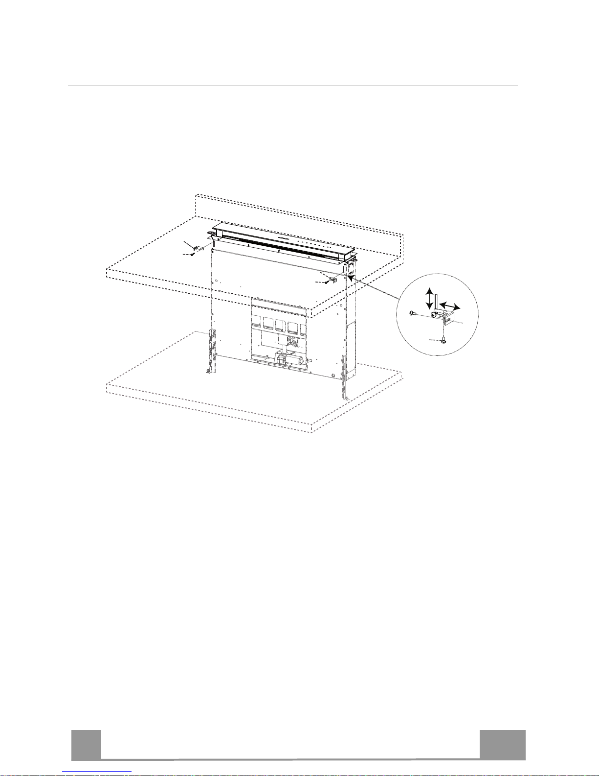
Fixing the Squaring Brackets
• Screw the brackets 7.3 to the Hood Canopy using the screws 12b provided, without
tightening completely.
• Using the screws 12c provided, fasten the other part of the brackets 7.3 either to the side
walls of the unit or to the lower part of the cooker top.
12b
7.3
12b
7.3
12c
• Tighten the screws 12c and 12b completely.
Page 13
EN
1
13
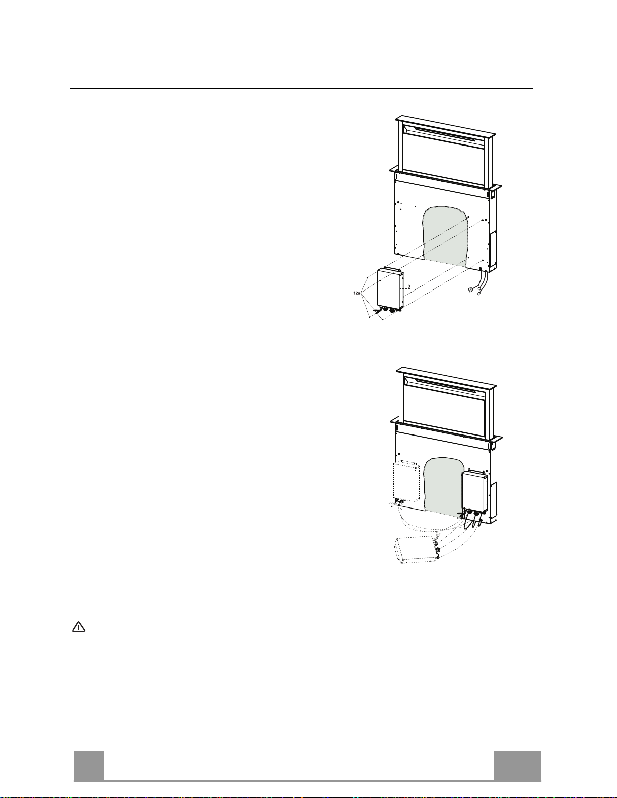
Fixing the Electric Unit
• Connect the Electric cables that come out of the lower
right hand part of the Hood Canopy to the Connectors
on the Electric unit.
• Each cable connector has a corresponding connector
on the Electric Unit, so take care not to make mistakes
when connecting up.
• Fix the Electric Unit to the Hood Canopy using the
screws 12a provided.
• The position indicated in the figure is only an option,
as if necessary it may also be fitted on the left of the
Hood Canopy or even left free on the base of the unit
if there are no structural or safety problems involved.
Warning..: Do not install the product in such a way that the wiring box is in contact with the floor.
Page 14
EN
1
14
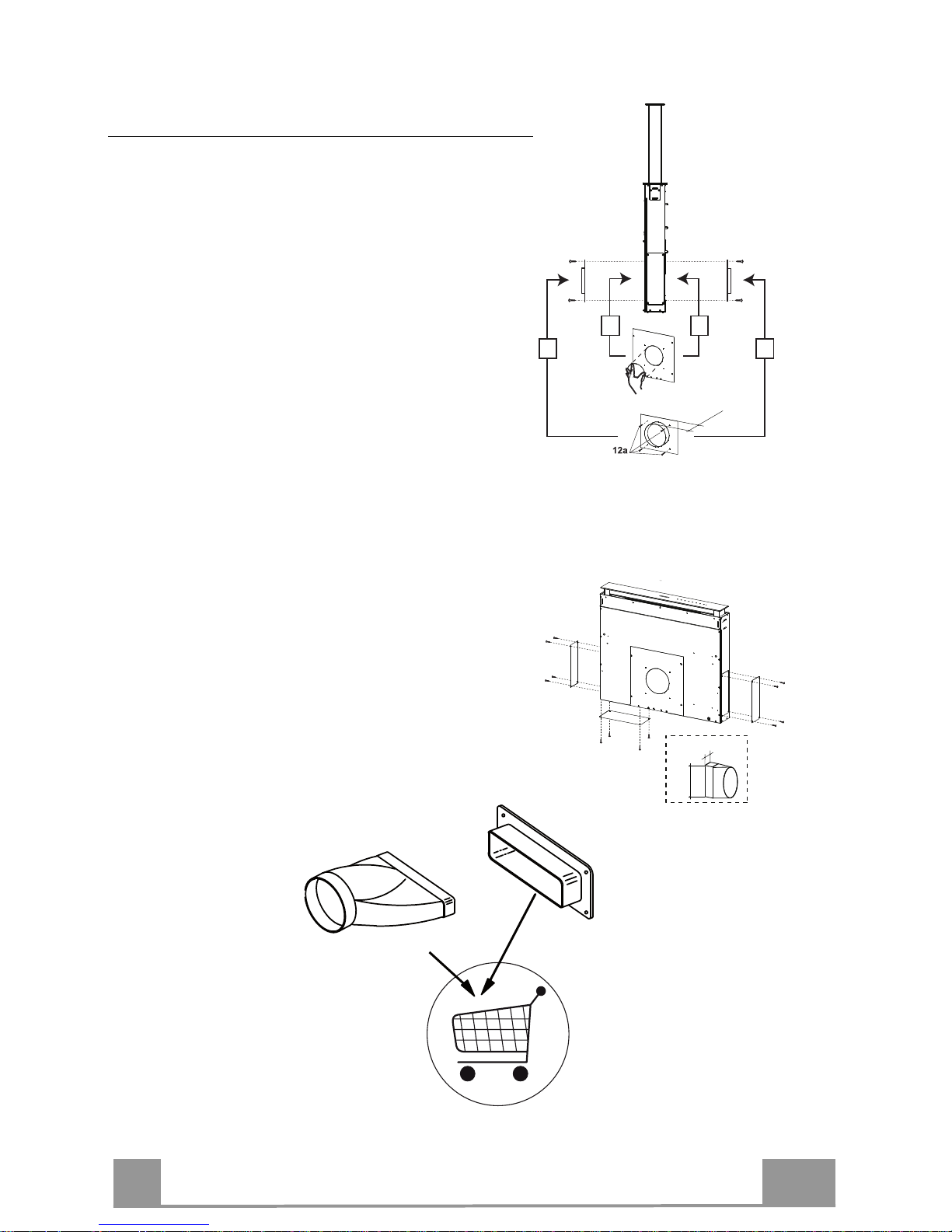
Connection to the Air outlet
To connect the Hood to the outlet pipe, select the
version that applies.
Standard Outlets
According to your decision (Right or Left), break the
outlet hole already marked and screw on Flange 2 using
the 4 screws 12a provided.
Optional Outlets
The Hood is fitted with three other possible outlets:
Right Side
Left Side
Bottom
According to your decision, unfasten the screws fixing
the cover and fit a connector, not provided, to the outlet
(the connector shown in the figure is merely an
example).
1 1
22
30mm
220mm
55mm
112.0040.359
112.0040.360
Page 15
EN
1
15
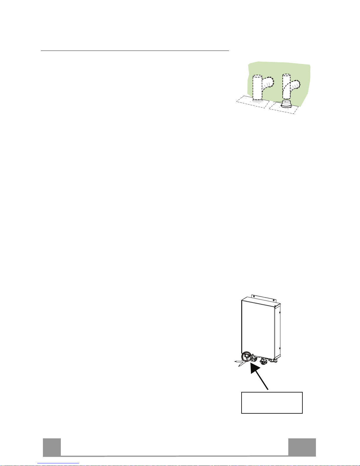
Connections
DUCTED VERSION AIR EXHAUST SYSTEM
When installing the ducted version, connect the hood to the
chimney using either a flexible or rigid pipe ø 150 or 120 mm,
the choice of which is left to the installer.
• To install a ø 120 mm air exhaust connection, insert the
reducer flange 9 on the hood body outlet.
• Fix the pipe in position using sufficient pipe clamps (not
supplied).
• Remove any activated charcoal filters.
ø 150
9
ø 120
ELECTRICAL CONNECTION
• Connect the hood to the mains through a two-pole switch
having a contact gap of at least 3 mm..
APPLIANCE
INLET
Page 16
EN
1
16
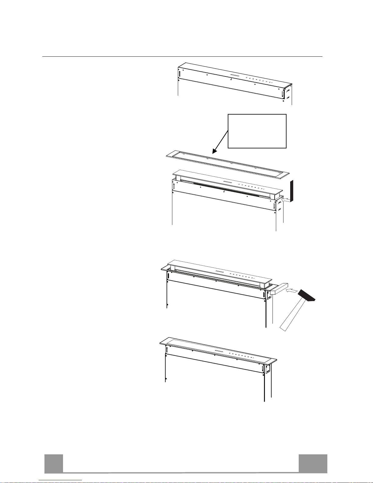
Warning..:
Handle
with care
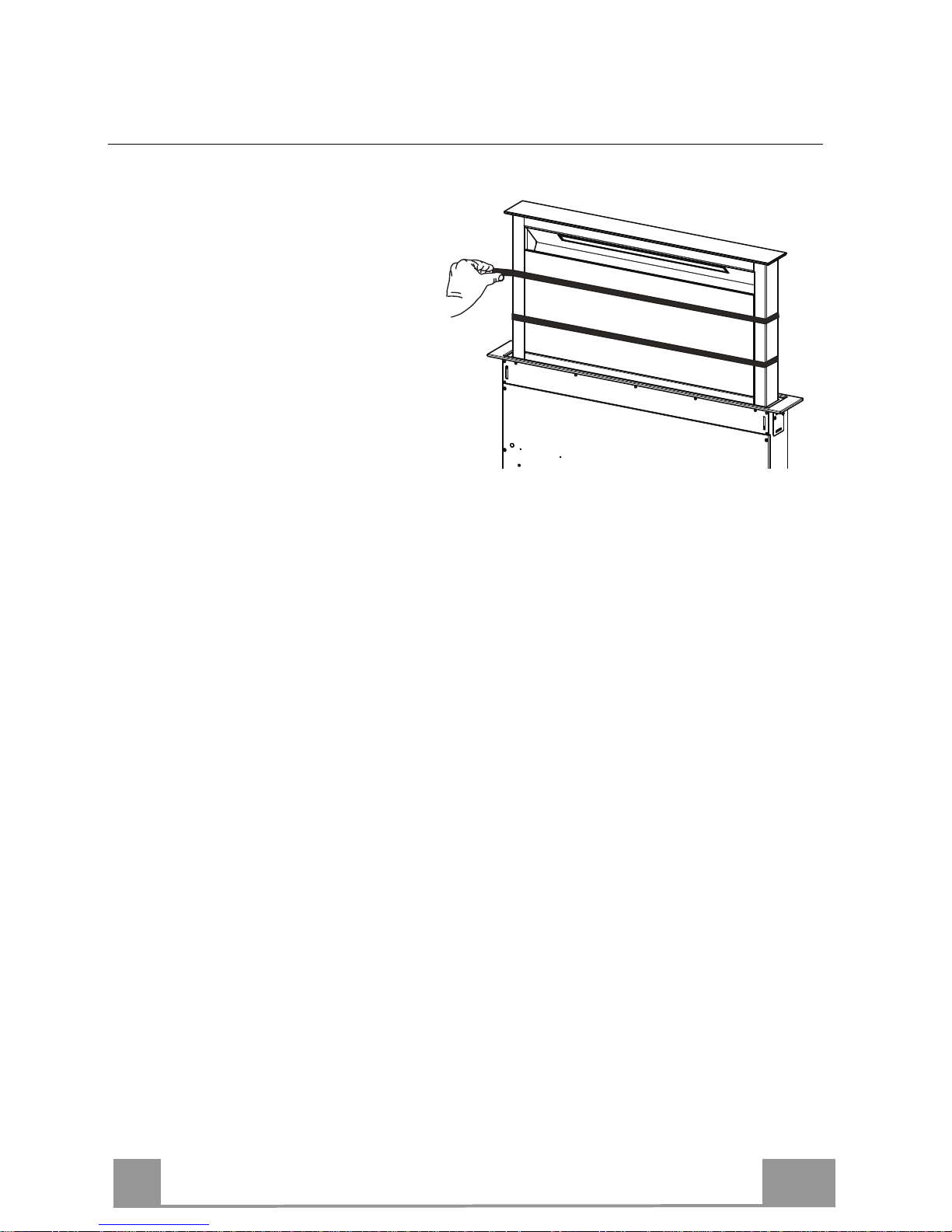
Fitting the Front element
• Lift the mobile hood canopy
(see paragraph on Use) by just a
few centimetres.
• To stop movement, simply
press down on the mobile
canopy as it lifts up.
Warning: Never block the
sliding door when it is opening
or closing, except during the
operations required to fit the
frame.
• Remove the sponge guards
from the corners of the glass.
• Take the front Frame and insert
it from above, making sure that
its tabs insert into the slots
provided on the Hood and
sliding it to the left.
Warning..: All the tabs must be
inserted.
• Use a tool (hammer) to tap all
along the front Frame from
right to left until it is
completely flush.
A piece of wood or similar
element can be inserted
between the hammer and the
front Frame to prevent any
damage.
• Please refer to the paragraph on
Use for indications of how to
return the mobile canopy to the
Standard position.
Page 17
EN
1
17
Surround Suction Panel
• Open the Hood Door (see
USE).
• Remove the 2 strips of adhesive
tape fastening the panel during
transport.
Page 18
EN
1
18
USE
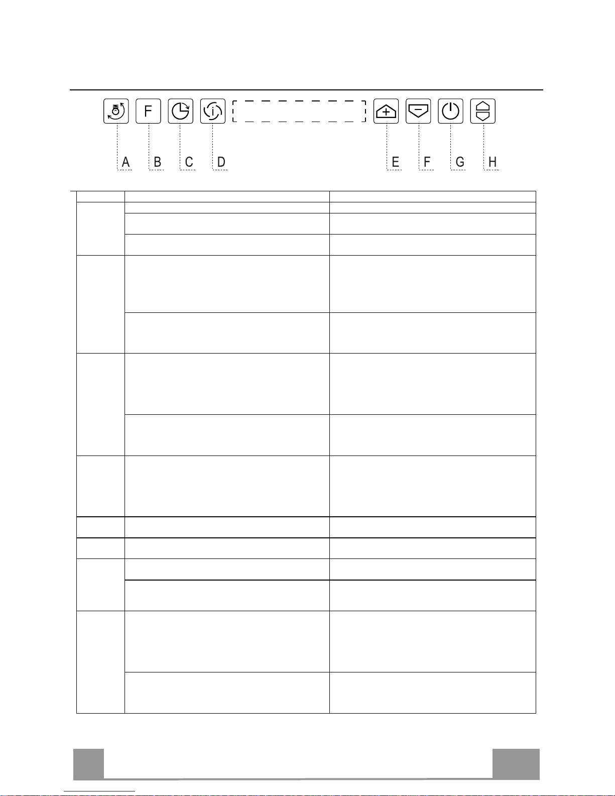
Control panel
Button
Function
LED button
A The button only works when the door is open.
Press Briefly = Turns the
Lights
On/Off at maximum
intensity.
Press and hold for 2 Seconds =
Turns
the
Courtesy lights
On/Off.
B
Door Open or Closed
Press briefly = performs a
Reset
of the Filter saturation
alarm.
After 100 hours in operation the Drop symbol is
displayed to indicate saturation of the Metal Grease
Filters.
After 200 hours in operation the letter C is displayed to
indicate saturation of the Activated Charcoal filters.
Door Open or Closed
Press and hold for 2 Seconds = Enables/Disables the
Activated Charcoal Filter Alarm with the Motor turned
off and no Filter Alarm triggered.
Symbol
C
flashes twice = A.C. Filter Alarm Activated
Symbol C flashes once = A.C. Filter Alarm Deactivated
C
Door Open.
Press briefly = Activates/Deactivates Delay mode,
causing automatic shutdown of the Motor and the
Lighting system from any speed with a 30’ delay. It is
disabled by pressing the same button again, turning the
motor off or closing the door.
Displays the
Clock
symbol.
Works both with Door Closed and Open with Motor +
Lights = Off.
Press and hold for 4 Seconds = Enables/disables the
Keyboard Lock.
All the LED buttons flash twice. During the Lock
the
LED buttons light up in sequence.
D
Only works with the Door Open.
Press briefly = Enables/Disables the Intensive speed. This
speed is timed to run for 6 minutes. At the end of this time
the system will return to the speed set previously.
It is disabled by pressing the same button again, turning
the motor off or closing the door.
Displays the
I
symbol.
E
Only works with the Door Open = i
ncreases the working
speed.
The number of lighted segments increases.
F
Only works with the Door Open =
decreases
the working
speed.
The number of lighted segments decreases.
G
Only works with the Door Open.
Press briefly = Turns the Motor On or Off
LEDs turn off
Door Open or Closed
Press and hold for 2 Seconds with Motor and Lights Off =
Enables/Disables the
Remote control
.
LED keys flash twice = Remote control Enabled
LED keys flash once = Remote control Disabled
H
Door Open =
Closes the Door
+ Lights and Motor Off
(*)
Door Closed = Opens the Door + Lights and Motor On.
Warning: If the Door remains partially open for any
reason, press the Button to complete the opening or
closing cycle.
(*) While the Door is Closing it will block in an
intermediate position after approximately 6 seconds. To
finish Closing you must press the button again and hold it
until the
door is completely closed.
Page 19
EN
1
19
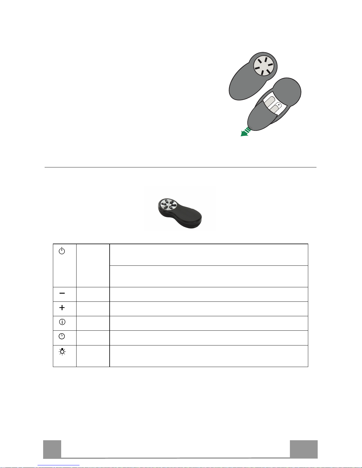
REMOTE CONTROL (OPTIONAL)
The appliance can be controlled using a remote control
powered by a 1.5 V carbon-zinc alkaline batteries of the
standard LR03-AAA type (not included).
• Do not place the remote control near to heat sources.
• Used batteries must be disposed of in the proper
manner.
Remote control panel
Warning..: The remote control receiver is deactivated when first supplied. To activate it, see the
paragraph Use Function of Button G.
Motor
Door Closed:
Opens the door, turns the motor on at speed one and turns the lights on at
maximum intensity.
Door Open:
Brief pressure: Motor On / Off
Pressed for 2 Seconds: Closes the Door and Motor + Lights = Off
Only with Door Open:
Decreases the working sp
eed each time it is pressed.
Only with Door Open:
Increases the working speed each time it is pressed.
Intensive
Only with Door Open:
Activates the Intensive function
Delay
Only with Door Open:
Activates the Delay function
Light
Only with Door Open:
Brief pressure: Lights On / Off
Pressed for 2 Seconds: Courtesy lights On / Off
Page 20
EN
2
20
MAINTENANCE
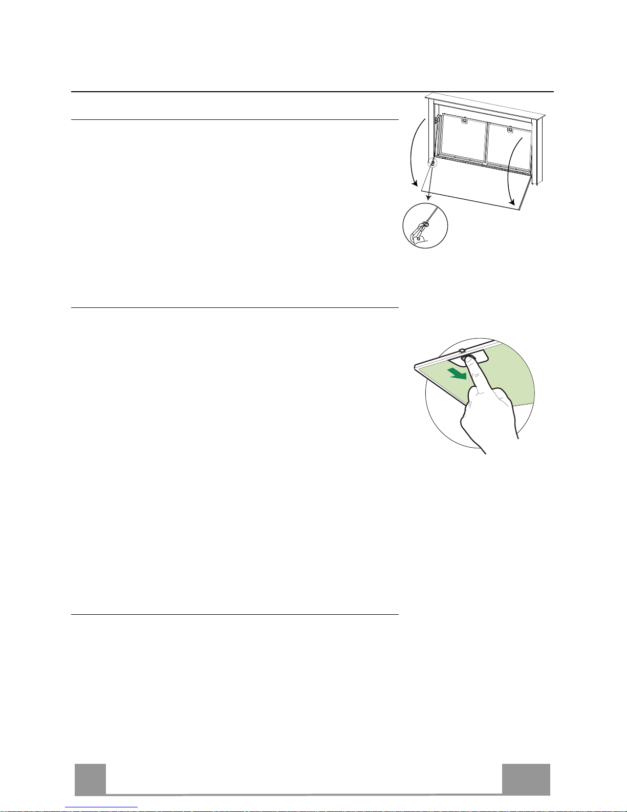
Cleaning the Comfort Panels
• Open the Comfort Panel by pulling it at the top.
• Unhook the security chain by opening the spring catch.
• Disconnect the panel from the hood canopy.
• The comfort panel must never be washed in the dishwasher.
• Clean the outside with a damp cloth and neutral detergent.
• Clean the inside using a damp cloth and neutral detergent; do
not use wet cloths or sponges, or jets of water; do not use
abrasive substances.
• On completing the operation, hook the panel and the spring
catch up to the hood canopy again and close it.
Metal grease filters
These can also be washed in the dishwasher, and need to be
cleaned whenever the “drop” symbol lights up or at least once
every 2 months use, or more frequently if use is particularly
intensive.
Resetting the alarm signal
• Turn the Lights and the Suction Motor off.
• Press button B (see paragraph on Use).
Cleaning the Filters
• Open the Door (see USE).
• Open the Comfort panel by pulling it.
• Remove the Filters one at a time, pushing them towards the
back of the unit and at the same time pulling downward.
• Wash the Filters without bending them, and leave them to dry
completely before replacing. (If the surface of the filter
changes colour as time goes by, this will have absolutely no
effect on the efficiency of the filter itself.)
• Replace, taking care to ensure that the handle faces forwards.
• Close the Comfort panel.
Lighting unit
Warning: This appliance is fitted with a white LED lamp classed
as 1M according to EN 60825-1: 1994 + A1:2002 + A2:2001
standards; maximum optical power emitted @439nm: 7µW. Do
not look directly at the light through optical devices (binoculars,
magnifying glasses…).
• For replacement contact technical support. ("To purchase
contact technical support")
Page 21
IT
2
21
CONSIGLI E SUGGERIMENTI
Le Istruzioni per l’uso si riferiscono ai diversi modelli di questo
apparecchio. Pertanto, si potrebbero trovare descrizioni di singole
caratteristiche che non appartengono al proprio apparecchio specifico.
INSTALLAZIONE
•
Il fabbricante non potrà ritenersi responsabile per eventuali danni risultanti
da un’installazione o utilizzazione impropria.
• La distanza minima di sicurezza tra il piano cottura
e la cappa aspirante è di 650 mm (alcuni modelli
possono essere installati a un’altezza inferiore;
vedere il paragrafo relativo alle dimensioni di lavoro
e all'installazione).
• Controllare che la tensione di rete corrisponda a
quella indicata sulla targa dati applicata all’interno
della cappa.
• Per gli apparecchi di Classe I, controllare che la rete di alimentazione
domestica disponga di un adeguato collegamento a massa.
Collegare l'aspiratore al condotto dei fumi mediante un tubo con diametro
minimo di 120 mm. Il percorso dei fumi deve essere il più corto possibile.
• Non collegare la cappa aspirante ai condotti fumari che trasportano fumi di
combustione (per es. caldaie, camini ecc.).
• Se l’aspiratore è utilizzato in combinazione con
apparecchi non elettrici (per es. apparecchi a gas),
deve essere garantito un sufficiente grado di
aerazione nel locale per impedire il ritorno di flusso
dei gas di scarico. La cucina deve avere un'apertura
comunicante direttamente con l'esterno per garantire
l'afflusso di aria pulita. Quando la cappa per cucina è utilizzata in
combinazione con apparecchi non alimentati dalla corrente elettrica, la
pressione negativa nel locale non deve superare 0,04 mbar per evitare che i
fumi vengano riaspirati nel locale dalla cappa.
• In caso di danneggiamento del cavo di alimentazione, occorre farlo sostituire
dal produttore o dal reparto di assistenza tecnica per evitare qualsiasi
rischio.
2°
Page 22
IT
2
22
• Se le istruzioni di installazione del piano cottura a gas specificano una distanza
maggiore di quella sopra indicata, è necessario tenerne conto. Devono essere
rispettate tutte le normative riguardanti lo scarico dell'aria.
• Usare solo viti e minuteria di tipo idoneo per la cappa.
Avvertenza: la mancata installazione delle viti o dei dispositivi di fissaggio in
conformità alle presenti istruzioni può comportare rischi di scosse elettriche.
• Collegare la cappa all'alimentazione di rete mediante un interruttore bipolare
con distanza tra i contatti di almeno 3 mm.
• Questa cappa aspirante può essere utilizzata in combinazione con un piano
cottura a gas dotato delle seguenti caratteristiche:
• Potenza massima 12,4 kW
• 5 fuochi come illustrato
nella figura
USO
•
La cappa aspirante è progettata esclusivamente per l’uso domestico allo scopo
di eliminare gli odori dalla cucina.
• Non usare mai la cappa per scopi diversi da quelli per cui è stata progettata.
• Non lasciare mai fiamme alte sotto la cappa quando è in funzione.
• Regolare l'intensità della fiamma in modo da dirigerla esclusivamente verso il
fondo del recipiente di cottura, assicurandosi che non ne avvolga i lati.
• Le friggitrici devono essere costantemente controllate
durante l’uso: l’olio surriscaldato potrebbe incendiarsi.
• Non cuocere al flambé sotto la cappa: si potrebbe
sviluppare un incendio.
• Questo apparecchio può essere utilizzato da bambini di
età non inferiore a 8 anni e da persone con ridotte capacità psico-fisicosensoriali o con esperienza e conoscenze insufficienti, purché attentamente
sorvegliati e istruiti su come utilizzare in modo sicuro l'apparecchio e sui pericoli
che ciò comporta. Assicurarsi che i bambini non giochino con l'apparecchio.
Pulizia e manutenzione da parte dell'utente non devono essere effettuate da
bambini, a meno che non siano sorvegliati.
2,6 kW
5 kW
1,9 kW
1,9 kW
1 kW
Page 23

IT
2
23
• “ ATTENZIONE: le parti accessibili possono diventare molto calde durante
l’uso degli apparecchi di cottura ”.
MANUTENZIONE
•
Spegnere o scollegare l’apparecchio dalla rete di alimentazione prima di
qualunque operazione di pulizia o manutenzione.
• Pulire e/o sostituire i filtri dopo il periodo di tempo specificato (pericolo di
incendio).
• I filtri antigrasso devono essere puliti ogni 2 mesi di funzionamento o più
frequentemente in caso di utilizzo molto intenso e possono essere lavati in
lavastoviglie.
• Il filtro al carbone attivo non è lavabile né è rigenerabile e deve essere
sostituito ogni 4 mesi di funzionamento circa o più frequentemente in caso di
utilizzo molto intenso.
• Pulire la cappa utilizzando un panno umido e un detergente liquido neutro.
Il simbolo sul prodotto o sulla sua confezione indica che il prodotto non
può essere smaltito come un normale rifiuto domestico. Il prodotto da smaltire
deve essere conferito presso un apposito centro di raccolta per il riciclaggio
dei componenti elettrici ed elettronici. Assicurandosi che questo prodotto sia
smaltito correttamente, si contribuirà a prevenire potenziali conseguenze
negative per l’ambiente e per la salute che potrebbero altrimenti derivare dal
suo smaltimento inadeguato. Per informazioni più dettagliate sul riciclaggio di
questo prodotto, contattare il Comune, il servizio locale di smaltimento rifiuti
oppure il negozio dove è stato acquistato il prodotto.
Page 24
IT
2
24
CARATTERISTICHE
Componenti
Rif. Q.tà Componenti di Prodotto
1 1 Corpo Cappa completo di: Comandi, Luce, Filtri
3 1 Gruppo Elettrico
4 1 Cornice Frontale
Rif. Q.tà Componenti di Installazione
7.1 2 Staffa Fissaggio al Fondale
7.2 2 Staffa Fissaggio al Piano
7.3 2 Staffa Laterale
12a 16 Viti 3,5 x 9,5
12b 2 Viti M4 x 8
12c 6 Viti 4 x 15
Q.tà Documentazione
1 Libretto Istruzioni
Page 25
IT
2
25
Ingombro
Page 26
IT
2
26
INSTALLAZIONE
Questa Cappa è predisposta per essere installata internamente al mobile della cucina in:
• Versione Aspirante: Evacuazione esterna.
• Versione Filtrante: Ricircolo interno.
Sequenza operazioni Installazione
• Foratura Piano e Montaggio Cappa
• Connessioni
• Controllo Funzionale
• Smaltimento Imballi
Foratura Piano di supporto
X
812
Attenzione
Una volta forato il Piano di supporto è possibile installare il Corpo Cappa in due modi :
• Infilando il Corpo Cappa dal basso ( X = 106 mm ).
• Infilando il Corpo Cappa dall’ alto ( X = 113 mm ).
IMPORTANTE
La distanza minima tra il foro praticato per i piano di cottura e quello per l'apparecchio di aspirazione deve essere di almeno 3-5 cm in funzione della resistenza del materiale utilizzato per il
top.
Page 27
IT
2
27
7.2
12a
7.2
12a
Inserimento Corpo Cappa nel piano dal basso
• Infilare il Corpo Cappa da sotto nel piano
di supporto precedentemente forato.
• Con l’aiuto di un supporto alzare
il Corpo Cappa finché il frontale
non fuoriesce dal Piano.
• Infilare le Staffe 7.2, come indicato in figura,
nelle apposite asole e fissarle con le Viti 12a in
dotazione.
• Centrare il Corpo Cappa rispetto all’ asola del
Piano Cottura.
• Fissare con 2 Viti 12c in dotazione il Corpo
Cappa al Piano e togliere i supporti.
Attenzione:
Se a causa del materiale del piano cottura non fosse possibile avvitare le viti 12c, usare una
piccola quantità di silicone per incollare le Staffe 7.2 al piano e lasciare asciugare bene prima
di continuare con l’installazione.
Page 28
IT
2
28
7.2
12a
7.2
12a
Inserimento Corpo Cappa nel piano dall’ alto
• Infilare le Staffe 7.2, come
indicato in figura, nelle apposite
asole e fissarle con le Viti 12a in
dotazione.
• Infilare il Corpo Cappa nel piano
cottura precedentemente forato.
• Centrare il Corpo Cappa rispetto
all’ asola del Piano Cottura.
• Fissare con 2 Viti 12c in dotazione
il Corpo Cappa.
Attenzione:
Se a causa del materiale del piano cottura non fosse possibile avvitare le viti 12c, usare una
piccola quantità di silicone per incollare le Staffe 7.2 al piano e lasciare asciugare bene prima
di continuare con l’installazione.
Page 29
IT
2
29
Fissaggio Staffe Inferiori
• Fissarle frontalmente le staffe 7.1 al Corpo Cappa con le Viti 12a in dotazione.
• Prima di serrare definitivamente le Staffe effettuare le regolazioni che permetteranno alle
staffe di appoggiare sulla base inferiore del piano evitando la deformazione delle staffe
superiori 7.2 come indicato in figura.
• Con l’aiuto di una Livella, livellare verticalmente il Corpo Cappa e fissarlo con 2 Viti 12c in
dotazione al Piano Inferiore.
• Fissare definitivamente le Viti 12a.
12c
12a
7.1
12a
7.1
Page 30

IT
3
30
Fissaggio Staffe a Squadra
• Avvitare le staffe 7.3 al Corpo Cappa con le Viti 12b in dotazione senza stringerle.
• Avvitare con le Viti 12c in dotazione l’altra parte delle staffe 7.3 o alle pareti laterali del
mobile o la parte inferiore del piano cottura.
12b
7.3
12b
7.3
12c
• Fissare definitivamente le Viti 12c e 12b.
Page 31

IT
3
31
Fissaggio Gruppo Elettrico
• Collegare i Cavi Elettrici che escono dalla
parte destra inferiore del Corpo Cappa ai
Connettori sul Gruppo Elettrico.
• Ogni Connettore dei Cavi ha il suo
corrispondente sul Gruppo Elettrico, quindi
prestare attenzione a non sbagliarsi sui
collegamenti.
• Fissare il Gruppo Elettrico al Corpo Cappa
con le Viti 12a in dotazione.
• La posizione indicata in figura è solo un’
opzione, in quanto a necessità può essere
montata anche sulla sinistra del Corpo
Cappa o addirittura lasciata libera sulla
base del mobile qualora non ci fossero
impedimenti strutturali o di sicurezza.
Attenzione..: Non installare il prodotto lasciando la scatola elettrica a contatto con il
pavimento.
Page 32

IT
3
32
Connessione all’ uscita Aria
Per collegare la Cappa alla tubazione di uscita scegliere
la versione più idonea al caso.
Uscite Standard
In base alla decisione presa (Destra o Sinistra),
rompere il foro di uscita già ricavato e avvitare la
Flangia 2 con le 4 viti 12a in dotazione.
Uscite Opzionali
La Cappa è provvista di altre tre possibili uscite:
Lato Destro
Lato Sinistro
Lato Inferiore
In base alla decisione presa Svitare le viti che fissano il
coperchio e applicare un raccordo, non in dotazione,
all’ uscita (il raccordo in figura è solo un esempio).
1 1
22
30mm
220mm
55mm
112.0040.359
112.0040.360
Page 33

IT
3
33
Connessioni
USCITA ARIA VERSIONE ASPIRANTE
Per installazione in Versione Aspirante collegare la Cappa alla
tubazione di uscita per mezzo di un tubo rigido o flessibile di
ø150 o 120 mm, la cui scelta è lasciata all'installatore.
• Per collegamento con tubo ø120 mm, inserire la Flangia di
riduzione 9 sull’Uscita del Corpo Cappa.
• Fissare il tubo con adeguate fascette stringitubo. Il materiale
occorrente non è in dotazione.
• Togliere eventuali Filtri Antiodore al Carbone attivo.
ø 150
9
ø 120
CONNESSIONE ELETTRICA
• Collegare la Cappa all’Alimentazione di Rete interponendo un
Interruttore bipolare con apertura dei contatti di almeno 3 mm.
Connettore
Alimentazione
Page 34

IT
3
34
Attenzione..:
Maneggiare
con cura
Montaggio Frontale
• Alzare il Corpo Mobile della
Cappa (Vedi paragrafo Uso)
soltanto di qualche centimetro.
• Per bloccare il movimento è
sufficiente fare una pressione
verso il basso sul Corpo Mobile
che si stà alzando.
Attenzione: Mai bloccare l’
Anta scorrevole durante le fasi
di apertura o chiusura, tranne
che nella fase per il montaggio
della cornice.
• Rimuovere le protezioni in
spugna dagli angoli del Vetro.
• Prendere la Cornice Frontale ed
infilarla dall’ alto facendo
attenzione che le sue linguette
si inseriscano nelle asole
predisposte sulla Cappa e farlo
scorrere verso sinistra.
Attenzione..: Tutte le linguette
devono essere inserite.
• Battere sulla Cornice Frontale
da Destra verso Sinistra con
l’aiuto di un arnese ( Martello)
fino a battuta.
Per non rovinarla si può usare
un elemento (pezzo di legno a
misura) tra il martello e la
Cornice Frontale.
• Fare riferimento al Paragrafo
Uso per riportare il Corpo
Mobile in posizione Standard.
Page 35

IT
3
35
Pannello Aspirazione Perimetrale
• Aprire l’Anta della Cappa
(Vedi Paragrafo Uso).
• Togliere le 2 strisce di nastro
adesivo che assicurano il
pannello solo durante il
trasporto.
Page 36

IT
3
36
USO
Quadro comandi
Tasto Funzione
Tasto Led
A Il tast
o Funziona solo ad Anta Aperta.
Pressione Breve = Accende/Spegne le
Luci
alla massima
intensità.
Pressione di 2 Secondi =
Accende/Spegne
le
Luci di Cort
e
sia
.
B
Anta Aperta o Chiusa
Pressione breve = effettua il
Reset
dell’allarme saturazione
Filtri.
Dopo 100 ore di Funzionamento Visualizza il
simbolo Goccia per segnalare la saturazione dei
Filtri Metallici.
Dopo 200 ore di Funzionamento Visualizza C per
segnalare la saturazione dei Filtri al Carb
o
ne Attivo.
Anta Aperta o Chiusa
Pressione di 2 Secondi = Abilita/Disabilita l’ Allarme Filtri al
Carbone Attivo con Motore Spento e senza Allarmi Filtri in
corso.
2 Lampeggi Simbolo
C
= Allarme Filtri C.A. Attivato
1 Lampeggio Simbolo C = Allarme Filtri C.A. Disattivato
C
Anta Aperta.
Pressione breve = Attiva/Disattiva il Delay, lo spegnimento
automatico ritardato di 30’, del Motore e dell’Impianto di
Illuminazione da qualsiasi Velocità. Si disattiva premendo il
medesimo tasto, spegnendo il mot
o
re o chiudendo l’anta.
Visualizza il simbolo
Orologio
.
F
unziona sia ad Anta Chiusa che Aperta con Motore + Luci =
Off.
Pressione di 4 Secondi = Abilita/disabilita il
Blocco Tastiera
.
Tutti i Tasti Led lampeggiano 2 volte. Durante il Blocco i
Led si accendono con una sequenza.
D
Funziona solo ad Anta Aperta
.
Pressione Breve = Abilita/Disabilita la velocità Intensiva. Tale
velocità è temporizzata a 6 minuti. Al termine del tempo il
sistema ritorna alla velocità precedentemente impostata.
Si disattiva premendo il medesimo tasto, spegnendo il motore o
chiud
endo l’anta.
Visualizza il simbolo
I
.
E
Funziona solo ad Anta Aperta = i
ncrementa la velocità di
esercizio.
Aumentano i segmenti accesi.
F
Funziona solo ad Anta Aperta =
decrementa la velocità di
esercizio.
Diminuiscono i segmenti accesi.
G
Funziona sol
o ad Anta Aperta.
Pressione Breve =
Accende/Spegne il Motore
Spegnimento dei Led
Anta Aperta o Chiusa
Pressione di 2 Secondi con Motore e Luci Off =
Abilita/Disabilita il Telecomando.
2 Lampeggi Tasti Led = Telecomando Abilitato
1 Lampeggio Tasti Led = Telecomando Disabilitato
H
Anta Aperta =
Chiude l’ Anta
+ Luci e Motore Off (*)
Anta Chiusa = Apre l’ Anta + Luci e Motore On.
Attenzione: Se l’ Anta per qualche motivo è parzialmente aperta,
premendo il Tasto finirà il suo ciclo o di apertura o di chius
ura.
(*) In fase di Chiusura dell’ Anta questa si bloccherà dopo circa
6 secondi in una posizione intermedia. Per Completare la
chiusura occorre premere nuovamente il pulsante tenendolo
premuto fino a completa chiusura.
Page 37

IT
3
37
TELECOMANDO (OPZIONALE)
Questo apparecchio può essere comandato per mezzo di
un telecomando, alimentato con pile alcaline zincocarbone da 1,5 V del tipo standard LR03-AAA (non
incluse).
• Non riporre il telecomando in prossimità di fonti di
calore.
• Non disperdere le pile nell’ambiente, depositarle
negli appositi contenitori.
Quadro comandi Telecomando
Attenzione..: Il ricevitore del Telecomando inizialmente è disattivato, per attivarlo vedi paragrafo Uso
Funzione Tasto G.
Motore
Anta Chiusa:
Apre l’ Anta, accende il Motore alla prima velocità e le Luci alla massima
intensità.
Anta Aperta:
Pressione breve: On / Off Motore
Premuto per 2 secondi: Chiude l’Anta e Motore + Luci = Off
Solo ad Anta Aperta:
Decrementa la velocità di esercizio ad ogni pre
s
sione.
Solo ad Anta Aperta:
Incrementa la velocità di esercizio ad ogni pre
s
sione.
Intensiva
Solo ad Anta Aperta:
Attiva la funzione Intensiva
Delay
Solo ad Anta Aperta:
Attiva la funzione Delay
Luce
Solo ad Anta Aperta:
Pressione breve: On / Off Luci
Pr
emuto per 2 secondi: On / Off Luci di Cortesia
Page 38

IT
3
38
MANUTENZIONE
Pulizia dei Comfort Panel
• Aprire il Comfort Panel tirandolo per la parte superiore.
• Sganciare il cavo di sicurezza aprendo il moschettone.
• Sganciare il pannello dal corpo cappa.
• Il comfort panel non va assolutamente lavato in lavastoviglie.
• Pulirlo esternamente con un panno umido e detersivo liquido
neutro.
• Pulirlo anche internamente utilizzando un panno umido e
detergente neutro; non utilizzare panni o spugne bagnate, né
getti d’acqua; non utilizzare sostanze abrasive.
• Ad operazione ultimata riagganciare il pannello e il
moschettone al corpo cappa e richiuderlo.
Filtri antigrasso metallici
Sono lavabili anche in lavastoviglie, e necessitano di essere lavati
quando si accende il simbolo “goccia” o almeno ogni 2 mesi
circa di utilizzo o più frequentemente, per un uso particolarmente
intenso.
Reset del segnale di allarme
• Spegnere le Luci e il Motore di aspirazione.
• Premere il tasto B (Vedi paragrafo Uso).
Pulizia Filtri
• Aprire l’anta (Vedi paragrafo Uso).
• Aprire il Comfort Panel tirandoli.
• Togliere i Filtri uno alla volta, spingendoli verso la parte
posteriore del gruppo e tirando contemporaneamente verso il
basso.
• Lavare i Filtri evitando di piegarli, e lasciarli asciugare prima
di rimontarli. (Un’eventuale cambiamento del colore della
superficie del filtro, che potrebbe verificarsi nel tempo, non
pregiudica assolutamente l’efficienza dello stesso.)
• Rimontarli facendo attenzione a mantenere la maniglia verso la
parte visibile esterna.
• Richiudere il Comfort Panel.
Illuminazione
Attenzione: Questo apparecchio è provvisto di una luce LED
bianca di classe 1M secondo la norma EN 60825-1: 1994 +
A1:2002 + A2:2001; massima potenza ottica emessa@439nm:
7µW. Non osservare direttamente con strumenti ottici (binocolo,
lente d’ingrandimento….).
• Per la sostituzione contattare l’Assistenza Tecnica. ("Per
l'acquisto rivolgersi all'assistenza tecnica").
Page 39

FR
3
39
CONSEILS ET SUGGESTIONS
Les instructions pour l’utilisation se réfèrent aux différents modèles de cet
appareil. Par conséquent, certaines descriptions de caractéristiques
particulières pourraient ne pas appartenir spécifiquement à cet appareil.
INSTALLATION
•
En aucun cas le fabricant ne peut être tenu pour responsable d’éventuels
dommages dus à une installation ou à une utilisation impropre.
• La distance de sécurité minimum entre le plan de
cuisson et la hotte aspirante est de 650 mm (certains
modèles peuvent être installés à une hauteur inférieure ;
voir le paragraphe concernant les dimensions de travail
et l’installation).
• Assurez-vous que la tension de votre secteur correspond
à celle indiquée sur la plaque des données appliquée à
l’intérieur de la hotte.
• Pour les appareils de Classe I, s’assurer que l’installation électrique de votre
intérieur dispose d’une mise à la terre adéquate.
Relier l’aspirateur au conduit de cheminée avec un tube d’un diamètre minimum
de 120 mm. Le parcours des fumées doit être le plus court possible.
• Ne pas relier la hotte aspirante aux conduits de cheminée qui acheminent les
fumées de combustion (par exemple de chaudières, de cheminées, etc.).
• Si vous utilisez l’aspirateur en combinaison avec des
appareils non électriques (par ex. appareils à gaz), vous
devez garantir un degré d’aération suffisant dans la pièce,
afin d’empêcher le retour du flux des gaz de sortie. La
cuisine doit présenter une ouverture communiquant
directement vers l’extérieur pour garantir l’amenée d’air
propre. Si vous utilisez la hotte de cuisine en combinaison avec des appareils
non alimentés à l’électricité, la pression négative dans la pièce ne doit pas
dépasser 0,04 mbar afin d’éviter que la hotte ne réaspire les fumées dans la
pièce.
• Si le cordon d’alimentation est endommagé, veuillez le faire remplacer par le
fabricant ou par un service après-vente agréé pour éviter tout risque d’accident.
2°
Page 40

FR
4
40
• Si les instructions d’installation du plan de cuisson à gaz spécifient une distance
supérieure à celle indiquée ci-dessus, veuillez impérativement en tenir compte.
Toutes les normes concernant l’évacuation de l’air doivent être respectées.
• Utiliser exclusivement des vis et des petites pièces du type adapté pour la hotte.
Attention : toute installation des vis et des dispositifs de fixation non conforme aux
présentes instructions peut entraîner des risques de décharges électriques.
• Brancher la hotte à l’alimentation de secteur avec un interrupteur bipolaire ayant une
ouverture des contacts d’au moins 3 mm.
• Cette hotte aspirante peut être utilisée en association avec un plan de cuisson à gaz
ayant les caractéristiques suivantes :
• Puissance maximum 12,4 kW
• 5 feux, comme illustré dans la figure.
UTILISATION
• Cette hotte aspirante a été conçue exclusivement pour un usage domestique, dans le
but d’éliminer les odeurs de cuisine.
• Ne jamais utiliser la hotte pour des objectifs différents de ceux pour lesquels elle a été
conçue.
• Ne jamais laisser un feu vif allumé sous la hotte lorsque celle-ci est en fonction.
• Régler l’intensité du feu de manière à l’orienter exclusivement vers le fond de la
casserole, en vous assurant qu’il ne déborde pas sur les côtés.
• Contrôler constamment les friteuses durant leur utilisation :
l’huile surchauffée risque de s’incendier.
• Ne pas flamber des mets sous la hotte : sous risque de
provoquer un incendie.
• Cet appareil n’est pas destiné à être utilisé par des enfants
d’un âge inférieur à 8 ans, ni par des personnes dont les capacités physiques,
sensorielles ou mentales sont diminuées ou qui ont une expérience et des
connaissances insuffisantes, à moins que ces enfants ou ces personnes ne soient
attentivement surveillés et instruits sur la manière d’utiliser cet appareil en sécurité et
sur les dangers que cela comporte. Assurez-vous que les enfants ne jouent pas avec
cet appareil. Le nettoyage et l’entretien de la part de l’utilisateur ne doivent pas être
effectués par des enfants, à moins que ce ne soit sous la surveillance d’une personne
responsable.
2,6 kW
5 kW
1,9 kW
1,9 kW
1 kW
Page 41

FR
4
41
• ATTENTION : les parties accessibles peuvent devenir très chaudes durant
l’utilisation des appareils de cuisson.
ENTRETIEN
•
Avant d’effectuer toute opération de nettoyage et d’entretien, éteindre ou
débrancher l’appareil du secteur.
• Nettoyer et/ou remplacer les filtres après le délai indiqué (danger
d’incendie).
• Nettoyer les filtres à graisse tous les 2 mois de fonctionnement ou plus
souvent en cas d’utilisation particulièrement intense. Ces filtres peuvent être
lavés au lave-vaisselle.
• Le filtre à charbon actif ne peut être ni lavé ni régénéré et il doit être
remplacé environ tous les 4 mois de fonctionnement ou plus souvent en cas
d’utilisation particulièrement intense.
• Nettoyer la hotte avec un chiffon humide et un détergent liquide neutre.
Le symbole marqué sur le produit ou sur son emballage indique que ce
produit ne peut pas être éliminé comme déchet ménager normal. Lorsque ce
produit doit être éliminé, veuillez le remettre à un centre de collecte prévu pour
le recyclage du matériel électrique et électronique. En vous assurant que cet
appareil est éliminé correctement, vous participez à prévenir des
conséquences potentiellement négatives pour l'environnement et pour la
santé, qui risqueraient de se présenter en cas d’élimination inappropriée. Pour
toute information supplémentaire sur le recyclage de ce produit, contactez
votre municipalité, votre déchetterie locale ou le magasin où vous avez acheté
ce produit.
Page 42

FR
4
42
CARACTERISTIQUES
Composants
Réf. Q.té Composants du produit
1 1 Corps de hotte équipé de : commandes, éclairage, filtres
3 1 Groupe électrique
4 1 Cadre frontal
Réf. Q.té Composants d’installation
7.1 2 Bride de fixation au fond
7.2 2 Bride de fixation au plan
7.3 2 Bride latérale
12a 16 Vis 3,5 x 9,5
12b 2 Vis M4 x 8
12c 6 Vis 4 x 15
Q.té Documentation
1 Manuel d’instructions
Page 43

FR
4
43
Encombrement
Page 44

FR
4
44
INSTALLATION
Cette hotte est prévue pour être installée à l’intérieur du meuble de cuisine en :
• Version aspirante : évacuation à l’extérieur.
• Version filtrante : recirculation intérieure.
Séquence des opérations d’installation
• Perçage du plan de support et montage de la hotte
• Connexions
• Contrôle fonctionnel
• Élimination des emballages
Perçage du plan de support
X
812
Attention
Après avoir percé le plan de support, le corps de hotte pourra être installé de deux manières :
• Enfiler le corps de hotte en passant par le bas ( X = 106 mm ).
• Enfiler le corps de hotte en passant par le haut ( X = 113 mm ).
Important
La distance minimale entre l'ouverture de la plaque de cuisson et l'autre pour le capot doit être
d'au moins 3-5 cm par rapport à la résistance du matériau utilisé pour le plan de travail.
Page 45

FR
4
45
7.2
12a
7.2
12a
Introduction du corps de hotte dans le plan en passant par le bas
• Enfiler le corps de hotte en
passant sous le plan de
support précédemment percé.
• À l’aide d’un support,
soulever le corps de hotte
jusqu’à ce que l’élément
frontal sorte du plan.
• Enfiler les brides 7.2, comme
indiqué dans la figure, dans les trous
prévus et les fixer avec les vis 12a
fournies.
• Centrer le corps de hotte par rapport
au trou du plan de cuisson.
• À l’aide de 2 vis 12c fournies,
fixer le corps de hotte au plan
et retirer les supports.
Attention :
Si le matériel du plan de cuisson ne permet pas de serrer les vis 12c, utiliser une petite quantité
de silicone pour coller les brides 7.2 au plan et bien laisser sécher avant de continuer
l’installation.
Page 46

FR
4
46
7.2
12a
7.2
12a
Introduction du corps de hotte dans le plan en passant par le haut
• Enfiler les brides 7.2, comme
indiqué dans la figure, dans les
trous prévus et les fixer avec les
vis 12a fournies.
• Enfiler le corps de hotte dans le
plan de support précédemment
percé.
• Centrer le corps de hotte par
rapport au trou du plan de
cuisson.
• Fixer le corps de hotte avec 2 vis
12c fournies.
Attention :
Si le matériel du plan de cuisson ne permet pas de serrer les vis 12c, utiliser une petite quantité
de silicone pour coller les brides de support 7.2 au plan et bien laisser sécher avant de
continuer l’installation.
Page 47

FR
4
47
Fixation des brides de support inférieures
• Fixer frontalement les brides de support 7.1 au corps de hotte avec les vis 12a fournies.
• Avant de serrer définitivement les brides de support, effectuer les réglages leur permettant
de s’appuyer sur la base inférieure du plan, en évitant la déformation des brides de support
supérieures 7.2, comme indiqué dans la figure.
• À l’aide d’un niveau, niveler verticalement le corps de hotte et le fixer au plan inférieur avec
2 vis 12c fournies.
• Fixer définitivement les vis 12a.
12c
12a
7.1
12a
7.1
Page 48

FR
4
48
Fixation des brides en équerre
• Visser les brides 7.3 au corps de hotte avec les vis 12b fournies, sans les serrer.
• Avec les vis 12c fournies, serrer l’autre côté des brides 7.3, soit aux parois latérales du
meuble, soit à la partie inférieure du plan de cuisson.
12b
7.3
12b
7.3
12c
• Fixer définitivement les vis 12c et 12b.
Page 49

FR
4
49
Fixation du groupe électrique
• Relier les câbles électriques sortant de la
partie inférieure droite du corps de hotte,
aux connecteurs sur le groupe électrique.
• Tous les connecteurs des câbles ont leur
correspondant sur le groupe électrique, par
conséquent, prenez garde de ne pas vous
tromper lors des connexions.
• Fixer le groupe électrique au corps de hotte
avec les vis 12a fournies.
• La position indiquée dans la figure est
seulement une option ; si nécessaire, il peut
également être monté à gauche du corps de
hotte ou même être laissé libre sur la base
du meuble, s’il n’y a pas d’empêchements
structurels ou de sécurité.
Attention : ne pas installer le produit en laissant le boîtier électrique au contact du sol.
Page 50

FR
5
50
Connexion à la sortie de l’air
Pour relier la hotte au conduit d’évacuation, choisir la
version la plus adaptée à votre cas.
Sorties standard
Selon la décision prise (droite ou gauche), casser le
trou d’évacuation déjà prévu et serrer la bride 2 avec les
4 vis 12a fournies.
Sorties en option
La hotte présente trois autres sorties possibles :
Côté droit
Côté gauche
Côté inférieur
Selon la décision prise, desserrer les vis de fixation du
couvercle et appliquer un raccord, non fourni, à la sortie
(le raccord illustré dans la figure est donné à titre
d’exemple).
1 1
22
30mm
220mm
55mm
112.0040.359
112.0040.360
Page 51

FR
5
51
Branchements
SORTIE AIR VERSION ASPIRANTE
En cas d’installation en version aspirante, brancher la hotte à la
tuyauterie de sortie via un tube rigide ou flexible de ø 150 ou 120
mm, au choix de l’installateur.
• En cas de branchement avec un tube de ø120 mm, insérer le
flasque de réduction 9 sur la sortie du corps de la hotte.
• Fixer le tube par des colliers appropriés. Le matériau
nécessaire n’est pas fourni.
• Retirer les éventuels filtres anti-odeur au charbon actif.
ø 150
9
ø 120
BRANCHEMENT ELECTRIQUE
• Brancher la hotte sur le secteur en interposant un interrupteur
bipolaire avec ouverture des contacts d’au moins 3 mm.
CONNECTEUR
D’ALIMENTATION
Page 52

FR
5
52
Attention :
manier avec
soin
Montage frontal
• Soulever le corps mobile de la
hotte de quelques centimètres
seulement. (Voir paragraphe
Utilisation).
• Pour bloquer le mouvement, il
suffit de faire pression vers le
bas sur le corps mobile qui est
en train de se soulever.
Attention : ne jamais bloquer
la porte coulissante durant les
phases d’ouverture ou de
fermeture, sauf pour le montage
du cadre.
• Retirer les protections en
mousse des coins du verre.
• Saisir le cadre frontal et
l’enfiler par le haut, en veillant
à ce que ses languettes
s’insèrent dans les trous prévus
sur la hotte, puis faire coulisser
le cadre vers la gauche.
Attention : toutes les
languettes doivent être insérées.
• Taper sur le cadre frontal de
droite à gauche à l’aide d’un
outil (marteau) jusqu’en butée.
Pour ne pas l’abîmer, vous
pouvez utiliser un élément
(morceau de bois de la bonne
dimension) entre le marteau et
le cadre frontal.
• Se référer au paragraphe
Utilisation pour ramener le
corps mobile en position
standard.
Page 53

FR
5
53
Panneau aspiration périmétrale
• Ouvrir la porte de la hotte.
(Voir paragraphe Utilisation).
• Retirer les deux bandes de
ruban adhésif qui fixent le
panneau seulement durant le
transport.
Page 54

FR
5
54
UTILISATION
Tableau des commandes
Touche
Fonction
Touche led
A La touche fonctionne seulement avec la porte ouverte.
Appui bref = Allume/Éteint l’
éclairage
à l’intensité maximum.
Appui de 2 secondes = Allume/Éteint les
lumières de
courtoisie.
B
Porte ouverte ou fermée
Appui bref = effectue le Reset de l’alarme de saturation filtres.
Après 100 heures de fonctionnement, le symbole de
la goutte s’affiche pour signaler la saturation des
filtres métalliques.
Après 200 heures de fonctionnement, C s’affiche pour
signaler la saturation des filtres à charbon actif.
Porte ouverte ou fermée
Appui de 2 secondes = Valide/Invalide l’alarme filtres à
charbon actif avec le moteur coupé et sans alarmes filtres en
cours.
2 Clignotements symbole
C
– Alarme filtres c.a. Activée
1 Clignotement symbole C – Alarme filtres c.a.
Désactivée
C
Porte ouverte.
Appui bref = Active/Désactive le Delay, l’extinction
automatique différée de 30’ du moteur et de l’installation
d’éclairage à partir de n’importe quelle vitesse. Pour la
désactiver, appuyer sur cette même touche, couper le moteur ou
fermer la porte.
Affiche le symbole
Horloge
.
Fonctionne aussi bien avec la porte fermée qu’ouverte avec
moteur + éclairage = Off.
Appui de 4 secondes = Valide/Invalide l
e
Blocage clavier
.
Toutes les touches leds clignotent 2 fois. Durant le
blocage, les touches leds s’éclairent en séquence.
D
Fonctionne seulement avec la porte ouverte.
Appui bref = Valide/Invalide la vitesse intensive. Cette vitesse
est temporisée à 6 minutes. À la fin de ce délai, le système
retourne à la vitesse précédemment réglée.
Pour la désactiver, appuyer sur cette même touche, couper le
moteur ou fermer la porte.
Affiche le symbole
I
.
E
Fonctionne seulement avec la porte ouverte = augmente la
v
itesse d’exercice.
Le nombre de segments allumés augmente.
F
Fonctionne seulement avec la porte ouverte = diminue la
vitesse d’exercice.
Le nombre de segments allumés diminue.
G
Fonctionne seulement avec la porte ouverte.
Appui bref =
Coupe/Dèmarrer le moteur
Extinction des leds.
Porte ouverte ou fermée
Appui de 2 secondes avec moteur et éclairage Off =
Valide/Invalide la
télécommande.
2 clignotements touches leds = Télécommande validée
1 clignotement touches leds = Télécommande invalidée
H
Porte ou
verte =
Ferme la porte
+ Éclairage et Moteur Off (*)
Porte fermée = Ouvre la porte + Éclairage et Moteur On.
Attention : Si, pour une raison quelconque, la porte est
partiellement ouverte, en appuyant sur la touche la porte
terminera son cycle d’ouverture
ou de fermeture.
(*) Durant la fermeture de la porte, elle s’arrêtera en position
intermédiaire après environ 6 secondes. Pour compléter la
fermeture, appuyer à nouveau sur la touche et garder l’appui
jusqu’à la fermeture complète.
Page 55

FR
5
55
TELECOMMANDE (FOURNIE SUR DEMANDE)
Il est possible de commander cet appareil au moyen
d’une télécommande, alimentée avec des piles alcalines
zinc-charbon 1,5 V du type standard LR03-AAA (non
compris).
• Ne pas ranger la télécommande à proximité de
sources de chaleur.
• Ne pas jeter les piles; il faut les déposer dans les
récipients de récolte spécialement prévus à cet effet.
Tableau des commandes - Télécommande
Attention : Initialement, le récepteur de la télécommande est désactivé, pour l’activer, voir le
paragraphe Utilisation Fonction Touche G.
Moteur
Porte fermée :
Ouvre la porte, branche le moteur à la première vitesse et l’éclairage à
l’intensité maximum.
Porte ouverte :
Appui bref : On / Off Moteur
Appuyée pendant 2 secondes : Ferme la porte et Moteur + Éclairage =
Off
Seulement avec la porte ouverte :
Diminue la vitesse de fonctionnement à chaque appui.
Seulement avec la porte ouverte :
Augmente la vitesse de fonctionnement à chaque appui.
Intensive
Seulement avec la porte ouverte :
Ac
tive la fonction Intensive
Delay
Seulement avec la porte ouverte :
Active la fonction Delay
Éclairage
Seulement avec la porte ouverte :
Appui bref : On / Off Éclairage
Appuyée pendant 2 secondes : On / Off Lumières de courtoisie
Page 56

FR
5
56
ENTRETIEN
Nettoyage des Comfort Panels
• Ouvrir le Comfort Panel en le tirant par le haut.
• Décrocher le câble de sécurité en ouvrant le mousqueton.
• Décrocher le panneau du corps de hotte.
• Ne jamais laver le Comfort Panel au lave-vaisselle.
• Le nettoyer à l’extérieur avec un chiffon humide et du
détergent liquide neutre.
• Le nettoyer également à l’intérieur avec un chiffon humide et
du détergent neutre ; ne pas utiliser de chiffons ou d’éponges
mouillées, ni de jets d’eau ; ne pas employer de substances
abrasives.
• À la fin de l’opération, raccrocher le panneau et le mousqueton
au corps de hotte et le refermer.
Filtres à graisse métalliques
Ils sont lavables même au lave-vaisselle et ils doivent être lavés
lorsque le symbole « goutte » s’inscrit à l’afficheur, ou au moins
tous les 2 mois d’utilisation environ ou plus souvent, en cas
d’utilisation particulièrement intensive.
Reset du signal d'alarme
• Éteindre l’éclairage et couper le moteur d’aspiration.
• Appuyer sur la touche B (Voir paragraphe utilisation).
Nettoyage des filtres
• Ouvrir la porte (Voir paragraphe Utilisation).
• Ouvrir le comfort panel en le tirant.
• Retirer les filtres un à un en les poussant vers la partie
postérieure du groupe et en tirant en même temps vers le bas.
• Laver les filtres en évitant de les plier et les laisser sécher avant
de les remonter. (Un changement de couleur de la surface du
filtre, susceptible de se produire avec le temps, ne nuit en rien à
son efficacité).
• Les remonter en veillant à ce que la poignée soit orientée vers
la partie visible externe.
• Refermer le comfort panel.
Éclairage
Attention : Cet appareil est doté d’une lumière LED blanche de
classe 1M conformément à la norme EN 60825-1: 1994 +
A1:2002 + A2:2001 : puissance optique maximum émise à
439nm : 7µW. Ne pas observer directement avec des instruments
optiques (jumelles, lentilles grossissantes…)
• Pour le remplacement, contacter le Service après-vente.
(« Pour l’achat, s’adresser au service après-vente »).
Page 57

DE
5
57
EMPFEHLUNGEN UND HINWEISE
Diese Gebrauchsanleitungen beziehen sich auf die verschiedenen Modelle
der Abzugshaube. Darum kann es möglich sein, dass die Beschreibung
bestimmter Merkmale für das vorliegende Gerät nicht zutrifft.
INSTALLATION
•
Der Hersteller haftet nicht für etwaige Schäden, die durch die fehlerhafte
Installation oder falschen Gebrauch entstehen könnten.
• Der min. Sicherheitsabstand zwischen Kochfeld
und Abzugshaube beträgt 650 mm (einige Modelle
können auch niedriger installiert werden; siehe
Absatz Installation).
• Kontrollieren Sie, ob die Netzspannung den Daten
des Typenschilds im Innern der Haube entspricht.
• Für Geräte der Klasse I muss kontrolliert werden,
ob das häusliche Versorgungsnetz korrekt geerdet
ist.
Die Absaughaube mit Hilfe eines Rohrs mit einem Mindestdurchmesser von
120 mm mit dem Rauchabzug verbinden. Der Verlauf des Rauchabzugs soll
so kurz wie möglich sein.
• Die Abzugshaube darf nicht an einen Schacht angeschlossen werden, in den
Rauchgase geleitet werden (z. B. von Heizkessel, Kaminen, usw.).
• Falls in dem Raum neben dem Abzug auch nicht
mit Strom betriebene Geräte (zum Beispiel
Gasgeräte) eingesetzt werden, muss für eine
ausreichende Belüftung gesorgt werden, damit der
Rückfluss der Abgase verhindert wird. Die Küche
muss eine direkte Öffnung nach Außen aufweisen,
damit ein ausreichender Luftaustausch
gewährleistet wird. Wird die Abzugshaube
zusammen mit nicht mit Strom betriebenen Geräte eingesetzt, darf der
Unterdruck im Raum 0,04 mbar nicht überschreiten, damit die Abgase nicht
wieder angesaugt werden.
• Schadhafte Kabel müssen durch den Hersteller oder vom Kundendienst
ausgewechselt werden, damit jedes Risiko ausgeschlossen wird.
2°
Page 58

DE
5
58
• Falls die Montageanweisungen für die gasbetriebene Kochmulde einen größeren
Abstand vorschreiben, als der oben angegebene, muss diese Vorgabe befolgt
werden. Es sind sämtliche Abluftvorschriften zu beachten.
• Nur für die Abzugshaube geeignete Schrauben und Kleinteile verwenden.
Achtung: Werden die Schrauben und Befestigungselemente nicht entsprechend
der vorliegenden Anleitungen verwendet, besteht Stromschlaggefahr.
• Die Abzugshaube mittels zweipoligem Schalter mit einer Öffnung der Kontakte
von mindestens 3 mm an das Netz anschließen.
• Diese Abzugshaube kann über gasbetriebenen Kochmulden mit den folgenden
Merkmalen verwendet werden:
• Max. Leistung 12,4 kW
• 5 Flammen, die wie in der
Abbildung gezeigt
GEBRAUCH
•
Die Abzugshaube wurde ausschließlich für den häuslichen Gebrauch entwickelt,
um Kochdünste zu beseitigen.
• Die Haube darf nur für die ihr zugedachten Zwecke benutzt werden.
• Unter der eingeschalteten Haube keine offenen Flammen benutzen.
• Die Flamme so regulieren, dass sie nicht über den Boden
des Kochgeschirrs hinausreicht.
• Fritteusen müssen während des Gebrauchs ständig
überwacht werden: überhitztes Öl könnte sich entzünden.
• Auf keinen Fall unter der Haube flambieren: Brandgefahr.
• Kinder ab 8 Jahren und Personen mit eingeschränkten physischen, sensorischen
oder psychischen Fähigkeiten, oder mit mangelnden Erfahrungen oder
Kenntnissen dürfen nicht mit dem Gerät umgehen, es sei denn, sie werden von
einer für ihre Sicherheit verantwortlichen Person beaufsichtigt oder angeleitet.
Sicherstellen, dass Kinder nicht mit dem Gerät herumspielen können. Reinigungsund Wartungsarbeiten dürfen nicht von unbeaufsichtigten Kindern durchgeführt
werden.
2,6 kW
5 kW
1,9 kW
1,9 kW
1 kW
Page 59

DE
5
59
• ACHTUNG: Die zugänglichen Teile können während des Gebrauchs der
Kochgeräte sehr heiß werden.
WARTUNG
•
Vor Reinigungs- oder Wartungsarbeiten am Gerät, muss dieses
ausgeschaltet und spannungslos gemacht werden.
• Die Filter stets nach den angegebenen Intervallen reinigen oder
auswechseln (Brandgefahr).
• Die Fettfilter sind alle 2 Monate oder bei intensiver Nutzung öfter zu reinigen
und können in der Spülmaschine gespült werden.
• Der Aktivkohlefilter ist weder waschbar, noch regenerierbar und muss bei
normalem Betrieb zirka alle 4 Monate oder auch öfter ausgewechselt
werden, je nach Intensität des Gebrauchs.
• Die Haube mit einem feuchten Lappen und einem neutralen
Reinigungsmittel abwischen.
Das Symbol am Produkt oder auf der Verpackung weist darauf hin, dass
das Gerät nicht als normaler Hausmüll entsorgt werden darf. Das ausrangierte
Gerät muss vielmehr bei einer speziellen Sammelstelle für elektrische und
elektronische Geräte abgegeben werden. Mit der vorschriftsmäßigen
Entsorgung des Gerätes trägt der Benutzer dazu bei, schädliche
Auswirkungen auf Umwelt und Gesundheit zu vermeiden. Weitere
Informationen zum Recycling dieses Produktes können bei der zuständigen
Behörde, der örtlichen Abfallbeseitigung oder bei dem Händler, der das Gerät
verkauft hat, eingeholt werden.
Page 60

DE
6
60
CHARAKTERISTIKEN
Komponenten
Bez. Menge Produktkomponenten
1 1 Haubenkörper, komplett mit: Bedienelemente, Beleuchtung, Filter
3 1 Elektrik
4 1 Frontrahmen
Bez. Menge Installationskomponenten
7.1 2 Bügel für die Befestigung am Boden
7.2 2 Bügel für die Befestigung am Kochfeld
7.3 2 Seitlicher Bügel
12a 16 Schrauben 3,5 x 9,5
12b 2 Schrauben M4 x 8
12c 6 Schrauben 4 x 15
Menge Dokumentation
1 Betriebsanleitung
Page 61

DE
6
61
Platzbedarf
Page 62

DE
6
62
MONTAGE
Diese Abzugshaube kann in Küchenmöbel eingebaut werden als:
• Abluftversion: Abluftleitung nach Außen.
• Umluftversion: Innere Rezirkulation.
Sequenz der Installationsarbeiten
• Bohrung der Kochfläche und Montage der Haube
• Anschlüsse
• Funktionskontrolle
• Entsorgung des Verpackungsmaterials
Bohrung der Auflagefläche
X
812
Achtung
Nachdem die Auflagefläche einmal gebohrt wurde, kann der Haubenkörper auf zwei Arten
installiert werden:
• Indem der Haubenkörper von unten eingeschoben wird (X = 106 mm).
• Indem der Haubenkörper von oben eingeschoben wird (X = 113 mm).
Wichtig
Der minimale Abstand zwischen dem Loch für das Kochfeld und dem für die Saugeinheit
gebohrt mindestens 3-5 cm abhängig von dem Widerstand des Materials für die oberste
verwendet wird.
Page 63

DE
6
63
7.2
12a
7.2
12a
Einsetzen des Haubenkörpers in die Arbeitsplattenmaterial von unten
• Den Haubenkörper von unten in die zuvor
gebohrte Auflagefläche schieben.
• Mit Hilfe einer Halterung den Haubenkörper
anheben, bis die Frontseite aus der
Kochfläche hervorragt.
• Die Bügel 7.2 wie abgebildet in die speziellen
Ösen einsetzen und mit den mitgelieferten
Schrauben 12a befestigen.
• Den Haubenkörper mit der Öse der Kochfläche
zentrieren.
• Den Haubenkörper mit den beiden
mitgelieferten Schrauben 12c an der Kochfläche
befestigen und die Halterungen entfernen.
Achtung:
Falls das Material der Kochfläche es nicht erlaubt, die Schrauben 12c einzuschrauben, werden die Bügel
7.2 mit etwas Silikon an der Kochfläche festgeklebt, wobei das Silikon gut trocknen muss, bevor mit der
Installation fortgefahren wird.
Page 64

DE
6
64
7.2
12a
7.2
12a
Einsetzen des Haubenkörpers in die Kochfläche von oben
• Die Bügel 7.2 wie abgebildet in
die speziellen Ösen einsetzen
und mit den mitgelieferten
Schrauben 12a befestigen.
• Den Haubenkörper in die zuvor gebohrte
Kochfläche schieben.
• Den Haubenkörper mit der Öse
der Kochfläche zentrieren.
• Den Haubenkörper mit
den beiden
mitgelieferten
Schrauben 12c
befestigen.
Achtung:
Falls das Material der Kochfläche es nicht erlaubt, die Schrauben 12c einzuschrauben, werden die Bügel
7.2 mit etwas Silikon an der Kochfläche festgeklebt, wobei das Silikon gut trocknen muss, bevor mit der
Installation fortgefahren wird.
Page 65

DE
6
65
Befestigung der unteren Bügel
• Die Bügel 7.1 mit den mitgelieferten Schrauben 12a am Haubenkörper befestigen.
• Vor dem definitiven Festziehen der Bügel diese so regulieren, dass sie an der unteren Basis
der Kochfläche aufliegen, und die oberen Bügel 7.2 nicht deformiert werden, wie in der
Abbildung gezeigt.
• Mit einer Wasserwaage den Haubenkörper vertikal ausrichten und mit den mitgelieferten
beiden Schrauben 12c an der unteren Kochfläche befestigen.
• Die Schrauben 12a definitiv festziehen.
12c
12a
7.1
12a
7.1
Page 66

DE
6
66
Befestigung der Winkelbügel
• Die Bügel 7.3 mit den mitgelieferten Schrauben 12b am Haubenkörper befestigen, ohne
festzuziehen.
• Den anderen Teil der Bügel 7.3 mit den mitgelieferten Schrauben 12c entweder an den
Seitenwänden des Möbels, oder an der Unterseite der Kochfläche befestigen.
12b
7.3
12b
7.3
12c
• Die Schrauben 12c und 12b definitiv festschrauben.
Page 67

DE
6
67
Montage der Elektrik
• Die rechts unten aus dem Haubenkörper
austretenden Stromkabel an die Verbinder
an der Elektrik anschließen.
• Für jeden Verbinder der Kabel befindet
sich an der Elektrik ein entsprechendes
Gegenstück, folglich darauf achten, dass
nicht falsch angeschlossen wird.
• Die Elektrik mit den mitgelieferten
Schrauben 12a am Haubenkörper
befestigen.
• Die abgebildete Position ist lediglich ein
Vorschlag, weil die Elektrik bei Bedarf
auch links am Haubenkörper montiert oder
sogar frei an der Basis des Möbels belassen
werden kann, sofern keine strukturellen
Hindernisse oder Sicherheitsbedenken
vorliegen.
Achtung: Bei der Installation darf die Abzweigdose nicht in Kontakt mit dem Fußboden bleiben.
Page 68

DE
6
68
Anschluss an den Luftauslass
Für den Anschluss der Haube an die Luftableitung die
für den jeweiligen Fall am besten geeignete Version
wählen.
Standardauslässe
Je nach erfolgter Wahl (Rechts oder Links), die bereits
vorbereitete Abzugsöffnung durchstoßen und mit den 4
mitgelieferten Schrauben 12a den Flansch 2
einschrauben.
Optionale Auslässe
Die Haube bietet drei weitere Auslassmöglichkeiten:
Rechte Seite
Linke Seite
Unterseite
Je nach der getroffenen Wahl die
Befestigungsschrauben der Abdeckung ausschrauben
und den Auslass mit einem Anschlussstück (nicht
mitgeliefert) versehen (das gezeigte Anschlussstück ist
rein hinweisend).
1 1
22
30mm
220mm
55mm
112.0040.359
112.0040.360
Page 69

DE
6
69
Anschluss der Abluftversion
Bei Abluftbetrieb kann die Haube vom Installateur wahlweise
mittels Rohr oder Schlauch (ø 150 oder 120 mm) an die
Außenrohrleitung angeschlossen werden.
• Bei Verwendung eines Anschlussrohres ø 120 den
Reduzierflansch 9 am Haubenaustritt anbringen.
• Das Rohr mit geeigneten Rohrschellen fixieren. Das hierzu
erforderliche Material wird nicht mitgeliefert.
• Eventuell vorhandene Aktivkohlefilter entnehmen.
Achtung! Alle Querschnittänderungen oder
Richtungsänderungen des Abluftkanals reduzieren die
Leistung der Haube.
ø 150
9
ø 120
ELEKTROANSCHLUSS
Vor der Installation die Netzspannung durch herausdrehen der
Sicherung oder ausschalten des Hauptschalters stromlos
machen.
• Bei Anschluss der Haube an das Stromnetz muss ein
zweipoliger Schalter mit einem Öffnungsweg von mindestens
3 mm zwischengeschaltet werden.
Achtung: Das Gerät nur an die Netzspannung die im
Typenschild angegeben ist anschließen.
STROMANSCHLUSS
Page 70

DE
7
70
Achtung:
Vorsichtig
behandeln
Frontale Montage
• Den beweglichen
Haubenkörper um wenige
Zentimeter anheben (Siehe
Absatz Gebrauch).
• Um die Bewegung zu
blockieren, einfach auf den
beweglichen Haubenkörper
einen Druck nach unten
ausüben.
Achtung: Die verschiebbare
Klappe nie während der Phase
des Öffnens oder Schließens
blockieren, außer wenn der
Rahmen montiert werden soll.
• Die Schutzecken aus
Schaumstoff von der
Glasscheibe nehmen.
• Den Frontrahmen zur Hand
nehmen, von oben so
einschieben, dass seine Laschen
in die Ösen an der Haube
passen und nach links gleiten
lassen.
Achtung: Alle Laschen müssen
eingeschoben sein.
• Mit einem Werkzeug
(Hammer) von rechts nach links
auf den Frontrahmen klopfen,
bis er sich am Anschlag
befindet.
Um Beschädigungen zu
vermeiden, kann ein passendes
Stück Holz zwischen Hammer
und Frontrahmen eingelegt
werden.
• Um den beweglichen
Haubenkörper wieder auf die
standardmäßige Position zu
bringen, den Absatz Gebrauch
konsultieren.
Page 71

DE
7
71
Umlaufendes Saugpaneel
• Die Klappe öffnen (siehe
Absatz Gebrauch).
• Die beiden Klebestreifen
entfernen, welche das Paneel
während des Transports
fixieren.
Page 72

DE
7
72
BEDIENUNG
Schalttafel
Taste
Funktion
LED Taste
A Die Taste funktioniert nur bei geöffneter Klappe.
Kurzes Drücken: schaltet die
Beleuchtung
bei maximaler
Intensität ein/aus.
2 Sek
unden langes Drücken =
schaltet die
Notbeleuchtung
ein/aus.
B
Klappe geöffnet oder geschlossen
Kurzes Drücken = führt das
Reset
des Alarms für
Filtersättigung aus.
Nach 100 Betriebsstunden zeigt das Symbol
Tropfen die Sättigung der Metallfilter an.
Nach 200 Betriebsstunden zeigt C die Sättigung der
Aktivkohlefilter an.
Klappe geöffnet oder geschlossen
2 Sekunden langes Drücken: Aktiviert/deaktiviert den Alarm
der Aktivkohlefilter bei abgestelltem Motor und ohne
vorliegende Filteralarme.
2 Mal Blinken
Symbol
C
= Alarm der Aktivkohlefilter
aktiviert
1 Mal Blinken Symbol C = Alarm der Aktivkohlefilter
deaktiviert
C
Klappe offen.
Kurzes Drücken: aktiviert/deaktiviert die Funktion Delay, das
automatische Abschalten von Motor und Beleuchtung mit einer
Verzögerung von 30', von jeder Geschwindigkeitsstufe aus. Wird
durch Drücken derselben Taste, Abstellen des Motors oder
Schließen der Klappe deaktiviert.
Zeigt das Symbol der
Uhr
.
Funktioniert bei geschlossener und geöffneter Klappe bei Motor
+ Beleuchtung = Off.
4 Sekunden langes Drücken: Aktiviert/deaktiviert die
Tastatursperre.
Alle Tasten blinken 2 Mal. Während der Tastatursperre
schalten sich die LEDs mit einer Sequenz ein.
D
Funktioniert nur bei geöffneter Klappe.
Kurzes Drücken: Aktiviert/deaktiviert die
Intensivgeschwindigkeit. Diese Geschwindigkeit ist auf 6
Minuten zeitgeregelt. Nach Ablauf dieser Zeit kehrt das System
zu der zuvor eingestellten Geschwindigkeit zurück.
Wird durch Drücken derselben Taste, Abstellen des Motors oder
Schließen der Kl
appe deaktiviert.
Zeigt das Symbol der
I
.
E
Funktioniert nur bei geöffneter Klappe = erhöht die
Betriebsgeschwindigkeit.
Die leuchtenden Segmente nehmen zu.
F
Funktioniert nur bei geöffneter Klappe = verringert die
Betriebsgeschwindigkeit.
Die leuchtende
n Segmente nehmen ab.
G
Funktioniert nur bei geöffneter Klappe.
Kurzes Drücken =
Der Motor On / Off
Die LEDs verlöschen
Klappe geöffnet oder geschlossen
2 Sekunden langes Drücken bei Motor und Beleuchtung Off =
Aktiviert/deaktiviert die Fernbedienung.
2 Mal Blinken der LED Tasten = Fernbedienung aktiviert
1 Mal Blinken der LED Tasten = Fernbedienung
deaktiviert
H
Klappe geöffnet
=
Klappe schließt
+ Beleuchtung und Motor
Off (*)
Klappe geschlossen = Klappe öffnet + Beleuchtung und Motor
On.
Achtung: Falls die Klappe aus irgendeinem Grund teilweise
offen ist, wird bei Drücken der Zyklus für Öffnen oder Schließen
beendet.
(*) Während der Schließphase der Klappe blockiert sich diese
nach 6 Sekunden in einer Zwischenposition. Um komplett zu
schließen die Taste erneut betätigen und solange gedrückt halten,
bis die Klappe ganz geschlossen ist.
Page 73

DE
7
73
FERNBEDIENUNG (OPTIO
N)
Dieses Gerät kann mit einer Fernbedienung gesteuert
werden, welche mit alkalischen Zink-Kohle-Batterien
1,5 V des Standardtyps LR03-AAA versorgt wird
(nicht im Lieferumfang enthalten).
• Die Fernbedienung nicht in die Nähe von
Hitzequellen legen.
• Batterien müssen vorschriftsmäßig entsorgt werden.
Bedienfeld der Fernbedienung
Achtung: Das Empfangsteil der Fernbedienung ist anfangs deaktiviert. Für die Aktivierung siehe
Absatz Gebrauch Funktion Taste G.
Motor
Klappe geschlossen:
Öffnet die Klappe und schaltet den Motor bei der ersten
Geschwindigkeitsstufe und stärkster Beleuchtung ein.
Klappe offen:
Kurzes Drücken: On / Off Motor
2 Sekunden langes Drücken: Schließt die Klappe und Motor +
Beleuchtung = Off
Nur bei geöffneter Klappe:
Vermindert bei jedem Drücken die Betriebsgeschwindigkeit.
Nur bei geöffneter Klappe:
Erhöht bei jedem Drücken die Betriebsgeschwindigke
it.
Intensivge
-
schwindigkeit
Nur bei geöffneter Klappe:
Aktiviert die Intensivgeschwindigkeit.
Delay
Nur bei geöffneter Klappe:
Aktiviert die Funktion Delay.
Beleuchtung
Nur bei geöffneter Klappe:
Kurzes Drücken: On / Off Beleuchtung
2 Sekunden l
anges Drücken: On / Off Notbeleuchtung
Page 74

DE
7
74
WARTUNG
Reinigung der Komfort-Paneele
• Die Oberseite des Komfort-Paneels nach oben herausziehen.
• Den Karabinerhaken öffnen und das Sicherheitsseil lösen.
• Das Paneel vom Haubenkörper lösen.
• Das Komfort-Paneel darf auf keinen Fall im Geschirrspüler gespült
werden.
• Die Außenflächen mit einem feuchten Lappen und einem neutralen
Flüssigreiniger säubern.
• Auch Innen mit einem feuchten Lappen und einem neutralen
Reinigungsmittel säubern; keine nassen Tücher oder Schwämme, oder
gar Wasser verwenden, und keine schleifenden Mittel einsetzen.
• Zuletzt das Paneel und den Karabinerhaken wieder am Haubenkörper
einhängen und schließen.
Metallfettfilter
Die Fettfilter sind spülmaschinengeeignet und müssen gewaschen
werden, sobald das Symbol “Tropfen” leuchtet, oder mindestens
alle 2 Monate, oder auch öfter, je nach Intensität des Gebrauchs.
Reset des Alarmsignals
• Die Beleuchtung und den Absaugmotor abstellen.
• Die Taste B drücken (siehe Absatz Gebrauch).
Reinigung der Filter
• Die Klappe öffnen (siehe Absatz Gebrauch).
• Die Paneele herausziehen.
• Die Filter einzeln ausbauen, indem sie in den hinteren Teil der
Gruppe geschoben und gleichzeitig nach unten gezogen
werden.
• Die Filter waschen, ohne sie zu verbiegen, und vor dem
erneuten Einbau trocknen lassen. (Die Farbe der
Filteroberfläche kann sich mit der Zeit verändern, was aber die
Wirksamkeit keinesfalls beeinträchtigt.)
• Nun die Filter wieder einbauen, so dass der Griff nach der
äußeren Sichtseite zeigt.
• Die Paneele wieder schließen.
Beleuchtung
LED-Strahler
• Für den Austausch der LED-Strahler wenden Sie sich bitte an den
Kundendienst.
Achtung: Dieses Gerät ist mit einer weißen LED-Lampe der Klasse 1M
gemäß EN 60825-1 ausgestattet: 1994 + A1:2002 + A2:2001; max.
gelieferte Lichtleistung @439nm: 7µW. Nicht direkt mit optischen
Instrumenten (Fernglas, Lupe, usw.) in das Licht schauen.
Page 75

TR
7
75
TAVSIYELER VE ÖNERILER
Kullanım talimatları, bu ev aletinin çeşitli modelleri için geçerlidir. Aynı
şekilde, bu ürünle ilgisi olmayan özelliklerin tanımlarını da görebilirsiniz.
MONTAJ
•
Yanlış veya hatalı montajdan doğan yaralanma ve hasarlar için imalatçı
yükümlü olmayacaktır.
• Pişiricinin üst kısmı ve davlumbaz arasındaki
minimum güvenlik mesafesi 650 mm'dir. (Bazı
modeller daha alçak mesafeye monte edilebilir,
lütfen çalışma boyutları ve montaj paragraflarına
bakınız.)
• Ana voltajın davlumbazın iç tarafına sabitlenmiş
olan derecelendirme plakasındaki ile uyumlu
olduğunu kontrol edin.
• I. sınıf ev aletleri için, ev güç kaynağının yeterli
topraklama sağladığından emin olun.
Aspiratörü egzoz bacasına minimum çapı 120 mm olan bir boru vasıtasıyla
bağlayın. Baca hattı mümkün olduğu kadar kısa olmalıdır.
• Davlumbazı tutuşabilir gazlar taşıyan egzoz kanallarına bağlamayın
(kazanlar, şömineler, vs.).
• Eğer davlumbaz elektrikli olmayan ev aletleri ile
birlikte kullanılacaksa (ör. gazlı ev aletleri), egzoz
gazının geri tepmesini engellemek adına odada
yeterli derecede bir havalandırma olması garanti
edilmelidir. Temiz havanın girişini garanti etmek
adına mutfakta temiz hava girişini sağlayan bir
açıklık olmalıdır. Davlumbazın elektrik dışında
enerji veren ev aletleri ile birlikte kullanılması
durumunda, davlumbazın gazları geri yollamasını engellemek adına odadaki
negatif basınç 0,04 barı aşmamalıdır.
• Güç kablosuna zarar gelmesi durumunda, herhangi bir riski engellemek
adına imalatçı veya teknik servis birimince değiştirilmelidir.
2°
Page 76

TR
7
76
• Gaz ocağının montaj talimatlarında yukarıda belirtilenden daha fazla bir
mesafe belirtilmişse, buna dikkat edilmesi gerekir. Hava deşarjı ile ilgili
yönetmeliklere uyulması gerekir.
• Davlumbazı desteklemek için sadece vida ve küçük parçalar kullanın.
Uyarı: İşbu talimatlar uyarınca vidaları veya sabitleme aletlerini
kullanmamak elektrik tehlikelerine yol açabilir.
• Davlumbazı, arasında en az 3mm irtibat mesafesi olan iki kutuplu bir anahtar
vasıtasıyla cereyana bağlayın.
• Bu davlumbaz, aşağıdaki özelliklerde gazlı ocaklarla birlikte kullanılabilir:
• Maksimum güç 12,4 kW
• Resimdeki gibi 5 ocaklı
KULLANIM
•
Davlumbaz mutfak kokularını gidermek adına ev kullanımı için
tasarlanmıştır.
• Davlumbazı asla tasarlandığı amaçlar haricinde kullanmayın.
• Davlumbaz çalışırken altında boşuna yanan yüksek ateş asla bırakmayın.
• Ateş yoğunluğunu sadece tencere altında kalacak ve yanlardan
taşmadığından emin olacak şekilde ayarlayın.
• Fritözler kullanım esnasında sürekli izlenmelidir:
fazla ısınmış yağ, ateş alabilir.
• Davlumbaz altında flambe yapmayınız; yangın
riski.
• Bu ev aleti, 8 yaş üstü çocuklar ve fiziksel,
duyusal veya akli yetersizliği olan veya tecrübe ve
bilgi eksikliği olan kişilerce bu kişilerin güvenliğinden sorumlu olan kişilerin
gözetimi altında veya ev aletinin kullanımı ile ilgili talimatlar kendilerine
verildiği durumlarda kullanılabilir. Çocuklar, ev aleti ile oynamamalıdır.
Temizleme ve bakım gözetimde olmadıklarında çocuklarca yapılmayacaktır.
2,6 kW
5 kW
1,9 kW
1,9 kW
1 kW
Page 77

TR
7
77
• “ DİKKAT: Pişirme aletleri ile kullanıldıklarında temas edilebilir parçalar
ısınabilir.”
BAKIM
•
Herhangi bir bakım işlemine başlamadan evvel ev aletini kapatın veya ana
güç kaynağından fişini çekin.
• Belirlenmiş zaman sonunda filtreleri temizleyin ve/veya değiştirin (Yangın
tehlikesi).
• Yağ filtreleri her 2 ayda bir veya yoğun kullanım olması durumunda daha sık
olarak temizlenmelidir ve bulaşık makinesinde yıkanabilirler.
• Aktif karbon filtresi yıkanabilir değildir, yeniden kullanılamaz ve her 4 ayda
bir veya yoğun kullanım olması durumunda daha sık olarak değiştirilmelidir.
• Davlumbazı nemli bir bez ve nötr sıvı deterjanla temizleyin.
Ürün üstündeki veya paketindeki sembolü, bu ürünün evsel atık olarak
değerlendirilmeyeceğinin göstergesidir. Elektrikli ve elektronik ekipmanın geri
dönüşümü için uygun toplama noktasına teslim edilmelidir. Bu ürünün doğru
şekilde bertaraf edildiğinden emin olarak, bu atık ürününün uygun olmayan
şekilde işlenmesinden doğacak çevre ve insan sağlığı için potansiyel olumsuz
sonuçların engellenmesine yardımcı olacaksınız. Bu ürünün geri dönüşümü ile
ilgili daha detaylı bilgi için lütfen yerel yetkili ofisiniz, evsel atık bertaraf hizmeti
veya ürünü satın aldığınız mağaza ile irtibata geçiniz.
Page 78

TR
7
78
ÖZELLIKLER
Parçalar
Ref. Miktar Ürün Aksamı
1 1 Davlumbaz Gövdesi şunlardan oluşur: Kumandalar, Işık ve Filtreler
3 1 Elektrik Grubu
4 1 Ön Çerçeve
Ref. Miktar Kurulum Aksamı
7.1 2 Askının arkalığa sabitlenmesi
7.2 2 Askının düzleme sabitlenmesi
7.3 2 Yanal Askılar
12a 16 Vida 3.5 x 9.5
12b 2 Vida M4 x 8
12c 6 Vida 4 x 15
Miktar Dokümantasyon
1 Kullanım Kitapçığı
Page 79

TR
7
79
Boyutlar
Page 80

TR
8
80
MONTAJ
Bu davlumbaz mutfaktaki dolap içine monte edilmek üzere tasarlanmıştır:
• Tahliyeli Sistem: Havayı dışarı atar.
• Filtreli Sistem: Havayı içeride dolaştırır.
Kurulum İşlem Sırası
• Delme ve Davlumbazı Monte Etme Planı
• Bağlantılar
• Fonksiyon Kontrolü
• Ambalajların Bertaraf Edilmesi
Destek düzleminin delinmesi
X
812
Dikkat
Destek düzlemi delindikten sonra, davlumbaz gövdesine iki şekilde monte edebilirsiniz:
• Aşağı taraftan davlumbaz gövdesinin içine takarak ( X = 106 mm ).
• Yukarıdan davlumbaz gövdesinin içine takarak ( X = 113 mm ).
Önemli
Ocak pişirme düzlemi için açılacak delik ile emme ünitesi arasındaki minimum mesafe üst
kısım için kullanılacak malzemenin dayanıklılığına göre en az 3-5 cm olmalıdır.
Page 81

TR
8
81
7.2
12a
7.2
12a
Davlumbaz gövdesini düzleme aşağıdan yerleştirmek
• Davlumbaz gövdesini daha önce delinmiş olan destek
yüzeyinin altından kaydırın.
• Bir destek yardımıyla
Davlumbaz gövdesini ön panel
düzlemden çıkana kadar kaldırın.
• Askıları 7.2, şekilde gösterildiği
gibi, yuvalarına yerleştirin ve
birlikte gelen vidalarla 12a
sabitleyin.
• Pişirme düzleminin yuvasına
göre davlumbaz gövdesini
ortalayın.
• Birlikte gelen 2 vida ile 12c Davlumbaz
gövdesini yerine sabitleyin ve desteği
çıkarın.
Dikkat:
Eğer pişirme yüzenin malzemesinden dolayı vidaları 12c sıkmak mümkün değilse, askıları 7.2
yüzeye yerleştirmek için az biraz silikon kullanın ve montaja devam etmeden evvel iyice
kurumaya bırakın.
Page 82

TR
8
82
7.2
12a
7.2
12a
Davlumbaz gövdesini düzleme yukarıdan yerleştirmek
• Askıları 7.2, şekilde gösterildiği
gibi, yuvalarına yerleştirin ve
birlikte gelen vidalarla 12a
sabitleyin.
• Davlumbaz gövdesini daha önce
delinmiş olan pişirme düzlemine
kaydırın.
• Pişirme düzleminin yuvasına göre
davlumbaz gövdesini ortalayın.
• Davlumbaz gövdesini
birlikte gelen 2 vida
12c ile emniyete alın.
Dikkat:
Eğer pişirme yüzenin malzemesinden dolayı vidaları 12c sıkmak mümkün değilse, askıları 7.2
yüzeye yerleştirmek için az biraz silikon kullanın ve montaja devam etmeden evvel iyice
kurumaya bırakın.
Page 83

TR
8
83
12c
12a
7.1
12a
7.1
İç Askının Sabitlenmesi
• Ön askıyı 7.1 davlumbaz gövdesine birlikte gelen vidalarla 12a sabitleyin.
• Askıları sıkmadan evvel, askıların düzlemin alt kısmını desteklemesine izin verecek ve üst
askıların 7.2 deformasyonunu engelleyecek şekilde ayarlamaları yapın.
• Bir terazi vasıtasıyla, davlumbaz gövdesini dikey olarak ayarlayın ve birlikte gelen vidalar
12c ile alt düzlem ile sabitleyin.
• Vidaları 12a iyice sıkıştırın.
Page 84

TR
8
84
Askı Grubunu Sabitleme
• Askıyı 7.3 Davlumbaz gövdesine birlikte gelen vidalarla 12b vidaları sıkmadan vidalayın.
• Birlikte gelen vidaları 12c askıların diğer tarafı ile 7.3 veya dolabın yan tarafına veya
pişirme yüzeyinin alt kısmına sabitleyin.
12b
7.3
12b
7.3
12c
• Vidaları 12c ve 12b iyice sıkıştırın.
Page 85

TR
8
85
Elektrik Grubunun Sabitlenmesi
• Davlumbaz gövdesinin alt sağ kısmından
çıkan elektrik kablosunu Elektrik Grubu
konektörlerine bağlayın.
• Her kablo konektörünün elektrik grubunda
denk gelen bağlantısı vardır, bu yüzden
bağlantıları karıştırmamak adına dikkatli
olun.
• Elektrik grubunu Davlumbaz gövdesine
birlikte gelen vidaları 12a kullanarak
sabitleyin.
• Şekilde gösterilen sadece bir seçenektir,
ihtiyaç durumunda davlumbaz gövdesinin
sol tarafına monte edilebilir hatta yapısal
zorunluluk veya güvenlik engeli olduğunda
dolap içinde serbest bırakılabilir.
Dikkat..: Elektrik kutusunu yere temas eder şekilde bırakarak ürünü monte etmeyin.
Page 86

TR
8
86
Hava çıkışı bağlantısı
Davlumbazı dış boruya bağlamak için, gövdeye en
uygun olan modeli seçin.
Standart çıktılar
Verilen karara göre (Sağ veya Sol), açılmış olan çıkış
deliğini genişleterek birlikte gelen 4 vida 12a ile flanşı
2 vidalayınız.
Opsiyonel çıktılar
Davlumbazın olası üç adet çıktısı bulunmaktadır:
Sağ Yan
Sol Yan
İç Kısım
Verilen karara göre, kapağı sabitleyen vidaları sökün ve
birlikte gelmeyen bir sabitleyiciyi çıkışa uygulayın
(resimdeki konektör bir örnektir).
1 1
22
30mm
220mm
55mm
112.0040.359
112.0040.360
Page 87

TR
8
87
Bağlantılar
ASPİRATÖRLÜ MODEL HAVA ÇIKIŞI
Aspiratörlü modelin montajı için, davlumbaz, montörün seçeceği
150 yada 120 mm çapında sert veya esnek bir boru ile çıkış
kanalına bağlanmalıdır.
• ø120 mm çapında boru ile bağlantı için, redüksiyon flanşını (9)
davlumbaz gövdesi çıkışına yerleştiriniz.
• Boruyu uygun kelepçelerle sıkarak sabitleyiniz. Bu malzeme
davlumbaz donanımıyla birlikte verilmemiştir.
• Varsa aktif karbonlu koku alma filtrelerini çıkarınız.
ø 150
9
ø 120
ELEKTRIK BAĞLANTISI
• Davlumbazι, temas noktalarι arasιnda 3 mm açιklιk olan çift
kutuplu bir anahtar üzerinden
elektrik şebekesine bağlayιn.
GÜÇ KONEKTÖRÜ
Page 88

TR
8
88
Ön tarafın montajı
• Davlumbazın hareketli
gövdesini (Kullanım
paragrafına bakınız) sadece
birkaç santim yükseltin.
• Hareketi bloklamak için
yükseltilmiş olan hareketli
gövdeyi aşağı doğru bastırmak
yeterlidir.
Dikkat: Çerçevenin montajı
adımı hariç, açılma veya
kapanma esnasında kayar
kanadı asla bloklamayınız.
• Camın köşelerinden koruyucu
köpüğü çıkarın.
• Ön çerçeveyi alın ve yukarıdan
aşağı doğru, iliklerin
davlumbazdaki yuvalarına
doğru oturduğundan emin
olarak kaydırın ve sola doğru
kaydırın.
Dikkat..: Bütün ilikler yerlerine
oturmuş olmalıdır.
• Ön çerçeveyi sağdan sola doğru
bir alet (çekiç) vasıtasıyla
durana kadar ittirin.
Hasar vermemek için, ön
çerçeve ile çekiç arasına bir şey
(tahta parçası) koyabilirsiniz.
• Hareketli gövdenin standart
konumunu görmek için
Kullanım paragrafına bakın.
Dikkat..:
Dikkatli
taşıyın
Page 89

TR
8
89
Emme Çevresi Panosu
• Davlumbazın kanadını açınız
(Kullanım paragrafına bakınız).
• Panoyu sadece taşınma
esnasında sabitlemek için
kullanılan 2 yapışkan şeridi
sökün.
Page 90

KULLANIM
Kumanda Tablosu
Tuş Fonksiyon
Led Tuşu
A Tuş sadece kanat açıkken çalışır.
Kısa Basış =
Işıkları
maksimum yoğunlukta açar/kapatır.
2 Saniye Basış
=
Courtesy Light'ı
açar/kapatır
.
B
Kanat Açık veya Kapalı
Kısa basış = Filtre doygunluk alarmını
Sıfırlar
.
100 Çalışma saati sonunda, Metal Filtrelerin
doygunluğunu belirten Damla sembolü
görüntülenir.
200 Çalışma saati sonunda, Aktif Karbonlu Filtrelerin
doygunluğunu belirten C görüntülenir.
Kanat Açık veya Kapalı
2 Saniye Basıldığında = Motor kapalı, alarm ve filtreler
çalışmıyorken Alarmla Etkinleştirilen Aktif Karbon
Filtrelerini etkinleştirir/devre dışı bırakır.
2 Kere yanıp sönen
C
sembolü = A.K. Filtre Alarmı
Devrede
1 Kere yanıp sönen C sembolü = A.K. Filtre Alarmı
Devre Dışı
C
Kanat Açık.
Kısa basış = Delay fonksiyonunu herhangi bir hızdaki Motor ve
Aydınlatmanın otomatik kapanmasını 30’ geciktirmek üzere
etkinleştirir/devre dışı bırakır. Motoru veya kanadı kapatmak
veya tuşa bas
mak sureti ile devre dışı bırakılır.
Saat
sembolü görüntülenir.
Kanat kapalı, Motor + Işıklar=Kapalı açıkken de çalışır.
4 Saniye basış =
Klavye Bloke Etmeyi
açar/kapatı
r.
Tüm Led tuşlar 2 kere yanıp söner. Kilitleme esnasında
ledler sıralı olarak yanar.
D
Sadece Kanat Açıkken çalışır.
Kısa Basış = Yoğun hızını etkinleştirir/devre dışı bırakır. Bu hız
6 dakikalık zaman ayarlıdır. Bittiğinde sistem eski hızına döner.
Motoru veya kanadı kapatmak veya tuşa basmak sureti ile devre
dışı bırakılır.
I
sembolü görüntülenir.
E
Sadece Kanat Açıkken çalışır = çalışma hızını a
rttırır. Açık segmanları arttırır.
F Sadece kanat açıkken çalışır = çalışma hızını
düşürür.
Açık segma
nları azaltır.
G
Sadece Kanat Açıkken çalışır.
Kısa Basış = Motoru açar/kapatır
Led kapalı
Kanat Açık veya Kapalı
Motor ve Işıklar kapalı iken 2 Saniye basış = Uzaktan
kumandayı etkinleştirir/devre dışı bırakır.
Led tuşu 2 kere yanıp söndüğünde = Uzakt
an kumanda
etkin
Led tuşu 1 kere yanıp söndüğünde = Uzaktan kumanda
devre dışı
H
Kanat Açık =
Kanadı kapatır
+ Işıklar ve Motor Kapalı (*)
Kanadı kapatır = Kanadı açar + Işıklar ve Motor Açık.
Dikkat: Herhangi bir sebeple kanat kısmen açık ise, tuşa basmak
döngüyü veya açılma veya kapanmayı sonlandıracaktır.
(*) Kanadın kapanma fazında, yaklaşık 6 saniye sonra orta
konumda kilitlenecektir. Kapanmayı tamamlamak için tuşa
yeniden basın ve tamamen kapanana kadar basılı tutun.
Page 91

TR
9
91
TELEKUMANDA (OPSİYONEL)
Bu cihaza bir telekumanda ile de komut verilebilir; bu
kumanda 1,5 Voltluk çinko-karbonlu LR03-AAA tipi
standart alkalin pillerle çalışır (dahil değildir).
• Telekumandayı ısı kaynakları yakınında
bırakmaynız.
• Pilleri çevreye atmayınız, bunlara ayrılmış çöp
toplama kaplarına atınız.
Uzaktan Kumanda Panosu
Dikkat..: Uzaktan kumandanın alıcısı devre dışıdır, etkinleştirmek için G fonksiyon tuşunun Kullanımı
paragrafına bakın.
Motor
Kanat Kapalı:
Kanadı açar, motoru ilk hızda çalıştırır ve ışıkları maksimum yoğunlukta
açar.
Kanat Açık:
Kısa basış: Motoru Açar/Kapatır.
2 saniye basılı tutulduğunda: Kanat kapanır ve Motor + Işıklar = Kapalı
Sadece Kanat Açık:
Her basışta çalışma hızını azaltır.
Sadece Kanat Açık:
Her basışta çalış
ma hızını arttırır.
Yoğun
Sadece Kanat Açık:
Yoğun işlevini etkinleştirir
Geciktir
me
Sadece Kanat Açık:
Gecikme (delay) işlevini aktive eder.
Işık
Sadece Kanat Açık:
Kısa basış: Işıkları Açar/Kapatır.
2 saniye basılı tutulduğunda: Courtesy Light
Açık / Kapalı
Page 92

TR
9
92
BAKIM
Comfort Panellerinin Temizliği
• Üst kısmından çekerek Comfort Panelini açın.
• Pimi açarak emniyet kablosunu çıkarınız.
• Paneli davlumbaz gövdesinden ayırın.
• Comfort panelini kesinlikle bulaşık makinesinde yıkamayın.
• Dış tarafını nemli bir bez ve sıvı nötr deterjanla temizleyin.
• İç tarafını nötr deterjan ve nemli bezle temizleyin; ıslak bez
veya sünger kullanmayın, su sıkmayın, aşındırıcı maddeler
kullanmayın.
• İşlem tamamlandıktan sonra, paneli ve pimi davlumbaz
gövdesine yeniden takın ve kapatın.
Yağlanmaya karşı metal filtreler
Bulaşık makinesinde yıkanabilirler, ekrana "damla" sembolünü
getirdiğinizde ya da yaklaşık her 2 aylık kullanım sonrasında
veya özellikle yoğun kullanım durumunda daha sıklıkla
yıkanmaları gerekir.
Alarm sinyalinin sıfırlanması
• Işıkları ve aspiratör motorunu kapatın.
• B tuşuna basın (Kullanım paragrafına bakınız).
Filtrelerin Temizlenmesi
• Kanadı açınız (Kullanım paragrafına bakınız).
• Comfort Panelini çekerek açınız.
• Yağ önleyici Filtreleri, grubun arka bölümüne doğru iterek ve
aynı anda aşağıya doğru çekerek teker teker çıkarın.
• Kıvrılmalarını engelleyerek filtreleri yıkayınız ve tekrar
takmadan önce kurumaya bırakın. (Filtrenin yüzeyinin
renginde zaman içerisinde gözlenebilecek olan değişimler,
filtrenin etkinliğini etkilemez.)
• Tutamağın dış görünür tarafta olduğuna dikkat ederek filtreleri
tekrar monte edin.
• Comfort Panelini tekrar kapatınız.
Aydınlatma
Dikkat: Bu cihazda EN 60825-1: 1994 + A1:2002 + A2:2001
normuna uygun olarak 1M sınıfı beyaz LED lamba kullanılmıştır;
@439nm'de yayılan azami optik güç: 7µW. Optik aygıtlarla
(dürbün, büyüteç....) doğrudan bakmayın.
• Değiştirmek için Teknik Servisle bağlantı kurun. ("Edinmek
için teknik servisle bağlantı kurun").
Page 93

Page 94

9
Page 95

Page 96

991.0281.530_ver3
Franke S.p.a.
Via Pignolini,2
37019 Peschiera del Garda (VR)
www.franke.it
 Loading...