

Page 1

Istruzioni per l’uso e l’installazione
Cappa
Instructions for use and installation
Cooker Hood
Mode d’emploi et installation
Hotte de Cuisine
Bedienungsanleitung und Einrichtung
Dunstabzugshaube
Kullan
ım ve montaj talimatları
Davlumbaz
FDL 654
FDL 954
IT
GB
FR
DE
TR
Page 2

IT
2
2
Libretto di Istruzioni
INDICE
CONSIGLI E SUGGERIMENTI ..............................................................................................................................................7
CARATTERISTICHE..............................................................................................................................................................8
INSTALLAZIONE....................................................................................................................................................................9
USO......................................................................................................................................................................................12
MANUTENZIONE.................................................................................................................................................................13
Page 3

EN
3
3
Instructions Manual
INDEX
RECOMMENDATIONS AND SUGGESTIONS....................................................................................................................14
CHARACTERISTICS............................................................................................................................................................15
INSTALLATION ....................................................................................................................................................................16
USE.......................................................................................................................................................................................19
MAINTENANCE....................................................................................................................................................................20
Page 4

FR
4
4
Manuel d’Instructions
SOMMAIRE
CONSEILS ET SUGGESTIONS ..........................................................................................................................................21
CARACTERISTIQUES.........................................................................................................................................................22
INSTALLATION ....................................................................................................................................................................23
UTILISATION........................................................................................................................................................................26
ENTRETIEN..........................................................................................................................................................................27
Page 5

DE
5
5
Bedienungsanleitung
INHALTSVERZEICHNIS
EMPFEHLUNGEN UND HINWEISE....................................................................................................................................28
CHARAKTERISTIKEN..........................................................................................................................................................29
MONTAGE............................................................................................................................................................................30
BEDIENUNG.........................................................................................................................................................................33
WARTUNG............................................................................................................................................................................34
Page 6

TR
6
6
Kullanim Kilavuku
IÇERIKLER
TAVSIYELER VE ÖNERILER ..............................................................................................................................................35
ÖZELLIKLER........................................................................................................................................................................36
MONTAJ...............................................................................................................................................................................37
KULLANIM............................................................................................................................................................................40
BAKIM...................................................................................................................................................................................41
Page 7
IT
7
7
CONSIGLI E SUGGERIMENTI
INSTALLAZIONE
• Il produttore declina qualsiasi responsabilità per danni dovuti ad installazione non corretta o non conforme alle regole dell’arte.
• La distanza minima di si curezza tra il Piano di cottura e la Cappa deve essere di 650 mm.
• Verificare che la tensione di rete corris ponda a quella riportata nella
targhetta posta all’interno della Cappa.
• Per Apparecchi in Classe Ia accertarsi che l’impi anto elettrico domestico garantisca un corretto scarico a terra.
• Collegare la Cappa all’uscita dell’aria aspirata con tubazione di diametro pari o superior e a 120 mm. Il p ercors o d el l a tubazi one deve es sere il più breve possibile.
• Non collegare la Cappa a condotti di scarico dei fumi prodotti da
combustione (caldaie, caminetti, ecc.).
• Nel caso in cui nella stanza vengano utilizzati sia la Cappa che apparecchi non azionati da energia elettrica (ad esempio apparecchi utilizzatori di gas), si deve provvedere ad una aerazione sufficiente
dell’ambiente. Se la cucina ne fosse sprovvista, praticare un’apertura
che comunichi con l’esterno, per garantire il richiamo d’aria pulita.
USO
• La Cappa è stata progettata esclusivamente per uso d omestico, per
abbattere gli odori della cucina.
• Non fare mai uso improprio della Cappa.
• Non las ciare fiamme libere a forte intensi tà sotto la Cappa in funzione.
• Regolare sempr e le fiamme in modo da evitare una evi dente fuoriuscita laterale delle stesse rispetto al fondo delle pentole.
• Controllare le fri ggitrici durante l’uso: l’olio surriscal dato potrebbe infiammarsi.
• Non preparare ali menti flambè s otto l a cappa da cuci na; pericolo d' incendio.
• La Cappa non deve essere utilizzata da bambini o persone non abilitate all’uso corretto.
MANUTENZIONE
• Prima di procedere a qualsi asi opera zione di manutenzione, dis inserire la Cappa togliendo la spina elettri ca o spegnendo l’interruttore generale.
• Effettuare una scrupolosa e tempestiva manutenzione dei Filtri secondo gli intervalli consigliati.
• Per la pulizia delle superfici della Cappa è sufficiente utilizzare un
panno umido e detersivo liquido neutro.
650 mm min.
Page 8
IT
8
8
CARATTERISTICHE
Ingombro
Componenti
Rif. Q.tà Componenti di Prodotto
1 1 Corpo Cappa completo di: Comandi, Luce , Filtri
2 1 Camino Telescopico formato da:
2.1 1 Camino Superiore
2.2 1 Camino Inferiore
9 1 Flangia di Riduzion e ø 150-120 m m
15 1 Raccordo Uscita Aria
Rif. Q.tà Componenti di Installazione
7.1 2 Staffe Fissaggio Cor po Cappa
7.2.1 2 Staffe Fissaggio Cami no Su periore
11 8 Tasselli
12a 8 Viti 4,2 x 44,4
12c 6 Viti 2,9 x 9, 5
12d 2 Viti M4 x 25
Q.tà Documentazione
1 Libretto Istruzioni
1
12c
12c
12c
2.1
2.2
2
7.2.1
12a 11
7.1
12a 11
12d
15
9
Page 9
IT
9
9
INSTALLAZIONE
Foratura Parete e Fissaggio Staffe
Tracciare sulla Parete:
• una linea Verticale fino al soffitto o al limite superiore, al centro della zona prevista per il montaggio della Cappa;
• una linea Orizzonta le a: 650 mm min. sop ra il Piano di Cottura, per installaz ione senza Fonda le;
alla quota H (H=altezza della parte in vista del Fondale), p er installazione con Fondal e.
• Appoggi are c ome indica to la St affa 7.2.1 a 1-2 mm dal soffitto o dal limite superiore, allineando
il suo centro (intagli) sulla linea Verticale di riferimento.
• Segnare i centri dei Fori della Staffa.
• Appoggiare come indicato la Staffa 7.2.1 a X mm sotto la prima staffa (X = altezza Camino Superiore in dotazione), a llineando il suo centro (intagli) sulla linea Verticale di riferimento.
• Segnare i centri dei Fori della Staffa.
• Appoggia re come indi cato, l a Staffa 7.1 a 95 mm dalla linea Verticale di riferimento, e 210 mm
sopra la linea Orizzontale di rif erimento.
• Segnare i centri dei Fori della Staffa.
• Ripetere ques ta operazi one dalla parte opposta.
FONDALE (OPTIONAL)
Il Fondale va montato p rima di mo ntare il Corpo Cappa e, se si desidera fissarlo all a parete sia superiormente che inferiormente, è necessario montarlo alla giusta altezza, prima del montaggio delle
basi. Ess endo questa operazione comp lessa va ef fettuata solamente dall’installatore della cucina o da
personale competente c h e conosca tutte le dimensioni finali dei mobili.
Limitandosi al solo fissaggio superiore, procedere come segue:
• Appoggiar e il Fondale sul la bas e inserendo la f aldina inf eriore tra il piano su periore e la parete,
centrandolo sulla li nea Vertical e di riferimento.
• Segnare i centri dei due fori della faldina superiore.
• Forare ø 8 mm i punti segnati.
• Inserire i tasselli 11 nei fori.
• Fissare le St affe, utilizzando le Viti 12a (4,2 x 44,4 ) in dotazi one.
• Se presente, f issare il Fondale, utilizzando le Viti 12a (4,2 x 44,4) in dotazione.
H
X
1÷2
650 min.
7.2.1
7.1
95
95
210
Page 10
IT 110
Montaggio Corpo Cappa
• Avvitare sulle Staffe 7.1, le 2 Viti 12d in dotazione.
• Agganciare il Corpo Cappa alle Staffe 7.1, centrandolo sulla
linea verticale.
• Agire sulle Viti 12d, dal sotto della Cappa, per livellare il Corpo Cappa.
7.1
12.d
Connessioni
USCITA ARIA VERSIONE ASPIRANTE
Per installazione in Versione Aspirante collegare la Cappa alla
tubazione di uscita per mezzo di un tubo rigido o flessibile di
ø150 o 120 mm, la cui scelta è lasciata all'installatore.
• Per collegamento con tubo ø120 mm, inserire la Flangia di riduzione 9 sull’Uscita del Corpo Cappa.
• Fissare il tubo con adeguate fascette stringitubo. Il materiale
occorrente non è in dotazione.
• Togliere eventuali Filtri Antiodore al Carbone attivo.
ø 120ø 150
9
USCITA ARIA VERSIONE FILTRANTE
• Applicare a pressione il Raccordo Uscita Aria 15 sull’Uscita
del Corpo Cappa.
• Assicurarsi della presenza del Filtro Antiodore al Carbone attivo.
15
Page 11
IT 111
CONNESSIONE ELETTRICA
• Collegare la Cappa all’Alimentazione di Rete interponendo un Interruttore bipolare con apertura dei
contatti di almeno 3 mm.
• Rimuovere i Filtri antigrasso (vedi par. “Manutenzione”) e assicurarsi che il connettore del Cavo di alimentazione sia correttamente inserito nella presa
dell’Aspiratore
Montaggio Camino
Camino superiore
• Allargare leggermente le due falde laterali, agganciarle dietro le Staffe 7.2.1 e richiuderle fino a battuta.
• Fissare lateralmente alle Staffe con 4 Viti 12c (2,9 x
9,5) in dotazione.
Camino inferiore
• Allargare leggermente le due falde laterali del Camino, agganciarle tra il Camino superiore e la parete e
richiuderle fino a battuta.
• Fissare lateralmente la parte inferiore al Corpo Cappa, con 2 Viti 12c (2,9 x 9,5) in dotazione.
• Assicurarsi che l’uscita del Raccordo 15 risulti in
corrispondenza delle bocchette del Camino.
12c
12c
12c
2.2
2.1
2
Page 12
IT 112
USO
L
V1 V2 V3
S
L Luci Accende e spegne l’Impiant o di Illuminazione.
S Led Led accension e Motore.
V1 Motore Accende e spegne il motore Aspirazione a velo cità minima, adatta ad un
ricambio d’aria continuo particolarmente silenzioso, in presenza di pochi
vapori di cottura.
V2 Velocità Velocità media, adatta alla maggior parte delle condizioni d’uso, dato
l’ottimo rapporto tra portata d’aria trattata e livello sonoro.
V3 Velocità Velocità massima, adatta a fronteggiare le massime emissioni di vapore di
cottura, anche per tempi prolungati.
Page 13
IT 113
MANUTENZIONE
Filtri antigrasso
PULIZIA FILTRI AN TIGR A SSO ME TAL L ICI AUTO PO RTAN TI
• Sono lavabili anche in lavastoviglie, e necessitano di essere
lavati ogni 2 mesi circa di utilizzo o più frequentemente, per un
uso particolarmente intenso.
• Togliere i Filtri uno alla volta, spingendoli verso la parte posteriore del gruppo e tirando contemp oraneamente verso il basso.
• Lavare i Filtri evitando di piegarli, e lasciarli asciugare prima
di rimontarli.
• Rimontarli facendo attenzione a mantenere la maniglia verso la
parte visibile esterna
Filtri antiodore al Carbone attivo (Versione Filtrante)
Il Filtro antiodore al Carbone attivo non è lavabile e non è rigenerabile, va sostituito ogni 4 mesi circa di utilizzo o più frequentemente, per un uso particolarmente intenso.
SOSTITUZIONE
• Togliere i Filtri antigrasso.
• Rimuovere i Filtri antiodore al Carbone attivo saturi, come indicato (A).
• Montare i nuovi Filtri, come indicato (B).
• Rimontare i Filtri antigrasso.
A
B
Illuminazione
SOSTITUZIONE LAMPADE
Lampade a incandescenza da 40 W
• Togliere i Filtri antigrasso metallici.
• Svitare le Lampade e sostituirle con nuove di uguali caratteristiche.
• Rimontare i Filtri antigrasso metallici.
Page 14

EN
114
RECOMMENDATIONS AND SUGGESTIONS
INSTALLATION
• The manufacturer will not be held liable for any damages resulting
from incorrect or improper installation.
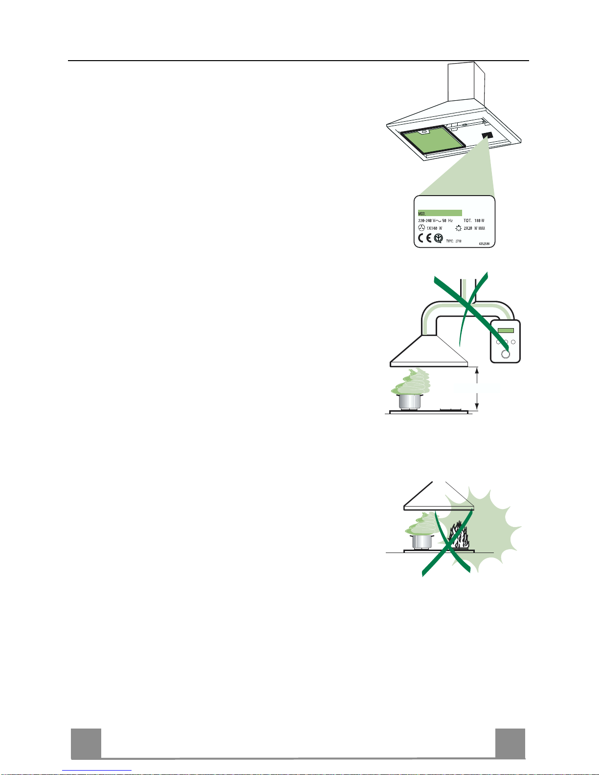
• The minimum safety distanc e between the cooker top and the extractor hood is 650 mm.
• Check that the mains voltage corresponds to that indicated on the
rating plate fixed to the inside of the hood.
• For Class I appl i ances , chec k t hat the domestic power s uppl y gua ran tees adequate earthing.
Connect the extractor to the ex haust flue through a pipe of minimum
diameter 120 mm. The route of the flue must be as short as possible.
• Do not connect the extractor ho od to exhaust ducts carrying comb ustion fumes (boilers, fireplaces, etc.).
• If the extractor is used in conjunction with non-electrical appliances
(e.g. gas burning appliances), a suffi cient degree of aeration must be
guaranteed in the room in order to prevent the backflow of exhaust
gas. The kitchen must h ave an opening communicati ng directly with
the open air in order to guarantee the entry of clean air.
USE
• The extractor hood has been des i gne d exc lus iv ely for domes tic use to
eliminate kitchen smells.
• Never use the hood for purposes other than for whi ch it has ben designed.
• Never leave high naked flames under the hood when it is in operation.
• Adjust the flame intensity to direct it onto the bottom of the pan only,
making sure that it does not engulf the sides.
• Deep fat fryers must be continuously monitored during use: overheated oil can burst into flames.
• Do not flambè under the range hood; risk of fire
• The hood should not be used by chil dren or persons not i nstructed in
its correct use.
MAINTENANCE
• Switch off or unplug the appliance from the mains supply before carrying out any maintenance work.
• Clean and/or replace the Filters after the specified time period.
• Clean the hood using a damp cloth and a neutral liquid detergent.
650 mm min.
Page 15

EN
115
CHARACTERISTICS
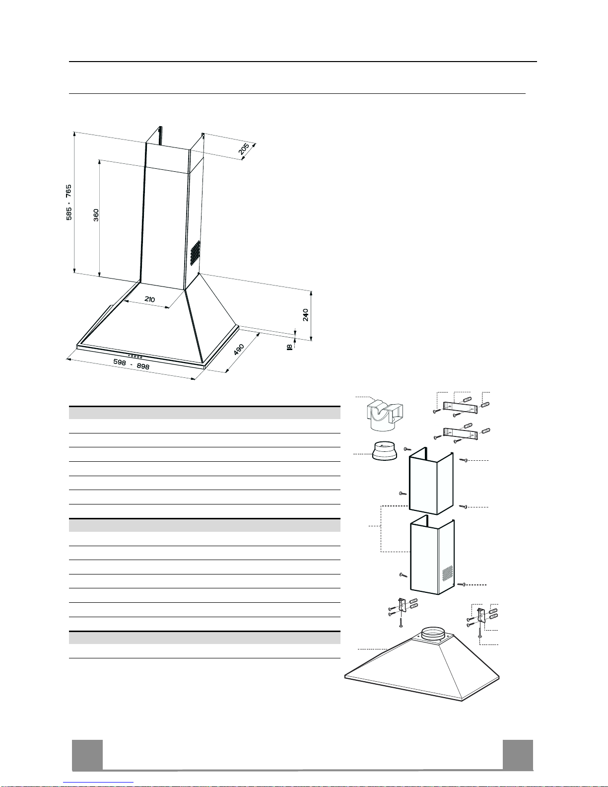
Dimensions
Components
Ref. Q.ty Product Components
1 1 Hood Body, complete with: Controls, Light, Blower,
Filters
2 1 Telescopic Chimney comprising:
2.1 1 Upper Section
2.2 1 Lower Section
9 1 Reducer Flange ø 150-120 mm
15 1 Air Outlet C onnection
Ref. Q.ty Installation Comp one nts
7.1 2 Hood Body Fixing Brack ets
7.2.1 2 Upper Chimney Section Fixing Brackets
11 8 Wall Plugs
12a 8 Screws 4.2 x 44,4
12c 6 Screws 2.9 x 9.5
12d 2 Screws M4 x 25
Q.ty Documentation
1 Instruction Manual
1
12c
12c
12c
2.1
2.2
2
7.2.1
12a 11
7.1
12a 11
12d
15
9
Page 16

EN
116
INSTALLATION
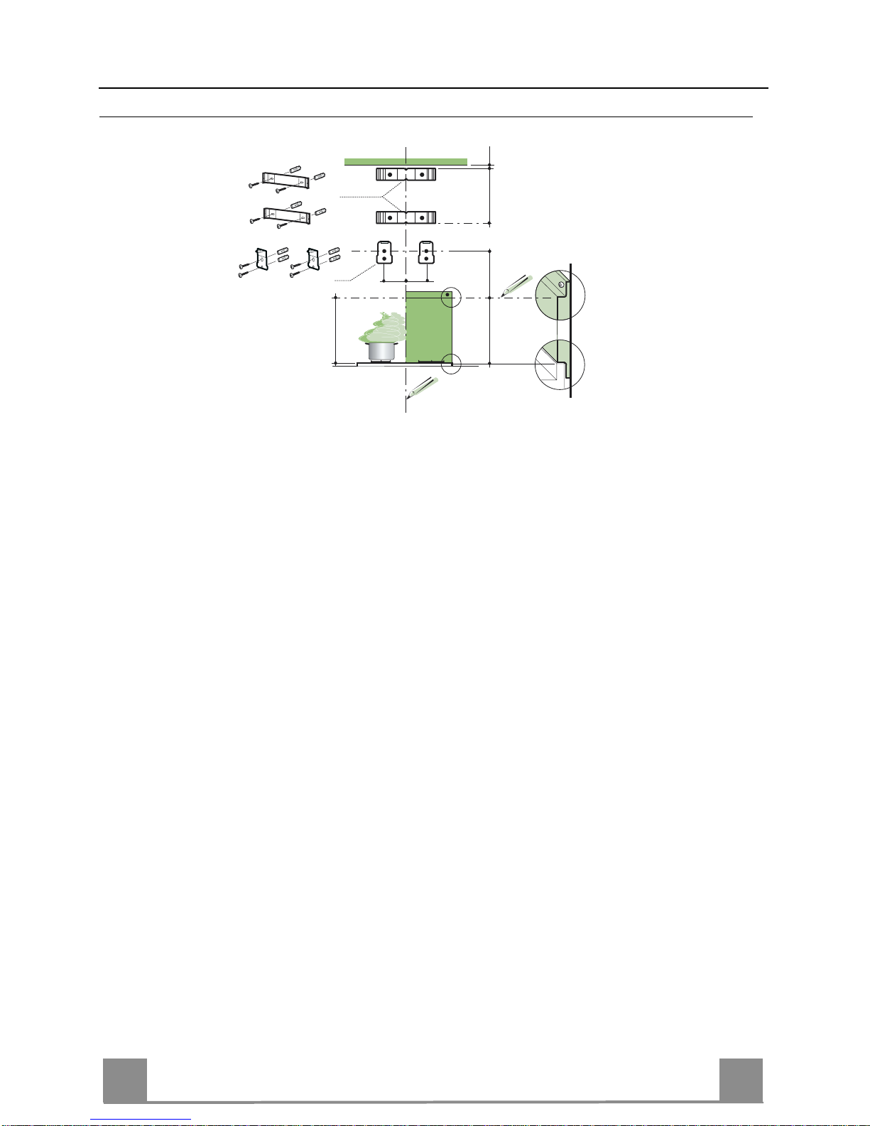
Wall drilling and bracket fixing
Wall marking:
• Draw a vertical line on the supporting wall up to the ceiling, or as high as practical, at the
centre of the area in which the hood will be installed.
• Draw a horizontal line at 650 mm above the hob for installation without the back panel, or at
height H (H=height of the visible part of the panel) for installation with the back panel.
• Place bracket 7.2.1 on the wall as shown about 1-2 mm from the ceiling or upper limit align-
ing the centre (n otch) with the vertical reference line.
• Mark th e wall at the centres of the h oles in the bracket.
• Place bracket 7.2.1 on the wall as shown at X mm below the first bracket (X = height of the
upper chimney section supplied), aligning the centre (notch) with the vertical line.
• Mark the wall at the centres of the holes in the bracket.
• Place bracket 7.1 as shown 95 mm from the vertical reference line and 210 mm above the
horizontal reference line.
• Mark the centres of the ho les in the bracket.
• Repeat this operation on the other side.
REAR PANEL (OPTIONAL)
The Rear Panel must be fitted before fixing the hood body and, if it is to be fixed at both top
and bottom, must be fitted at the correct height prior to installing the bases. As this operation is
rather complex, it should be carried out either by the kitchen installer or a qualified person
who knows the final dimensions of the units.
For fixing at the top only, proceed as follows:
• Rest the back pan el on t he base, i nserti ng the l ower plate b etween the upp er surface and the
wall, centring it on the vertical reference line.
• Mark th e centres of the two holes i n the upper plate.
• Drill ø 8 mm holes at all the centre points marked.
• Insert the wall plugs 11 in the holes.
• Fix the brackets usi ng the 12a screws (4,2 x 44,4) supplied.
• Fix the back panel (where present) using the 12a (4,2 x 44,4) screws supplied.
H
X
1÷2
650 min.
7.2.1
7.1
95
95
210
Page 17

EN
117
Mounting the hood body
• Screw the two screws 12d supplied onto the brackets 7.1.
• Hook the hood body onto the bracket 7.1, centring it around
the vertical line.
• Use the adju sting screws 12d underneath the hood to level the
hood body.
7.1
12.d
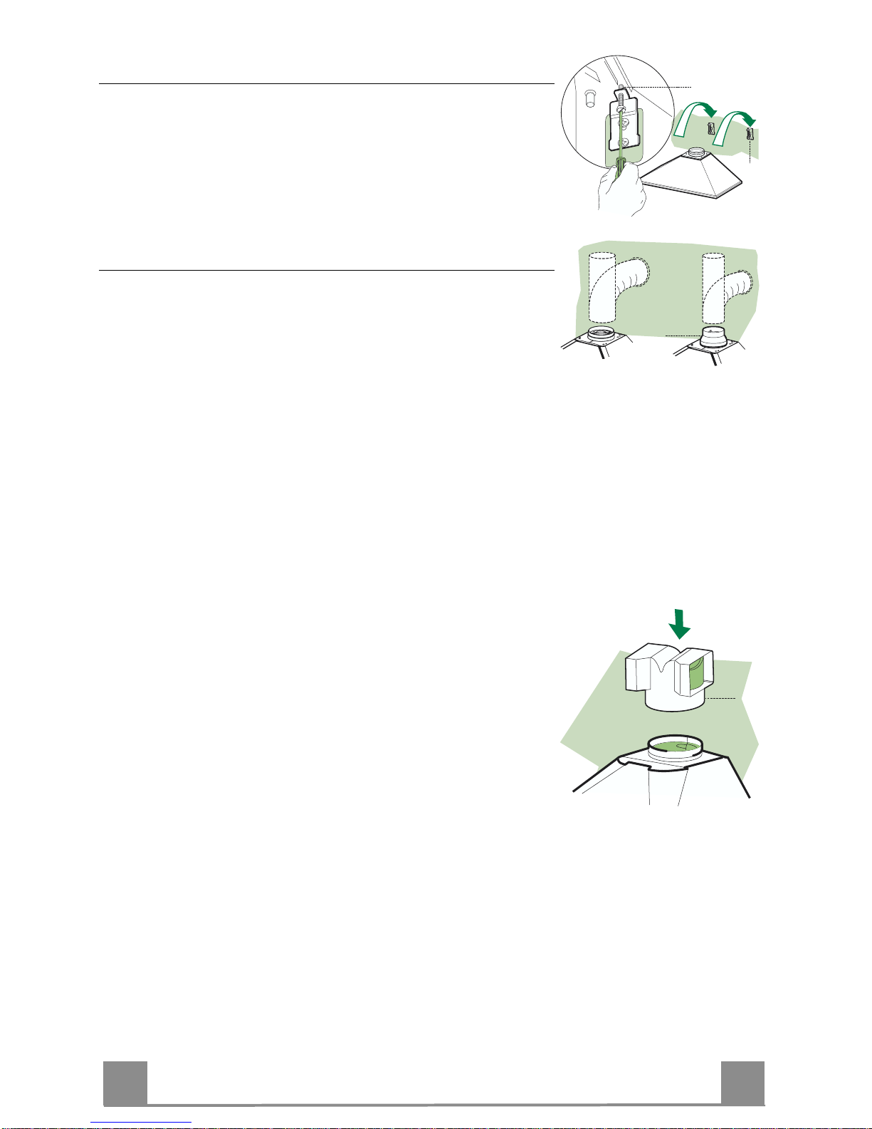
Connections
DUCTED VERSION AIR EXHAUST SYSTEM
When installing the ducted version, connect the hood to the
chimney using either a flexible or rigid pipe ø 150 or 120 mm,
the choice of which is left to the installer.
• To install a ø 120 mm air exhaust connection, insert the reducer flange 9 on the hood body outlet.
• Fix the pipe in position using sufficient pipe clamps (not supplied).
• Remove any activated charcoal filters.
ø 120ø 150
9
RECIRCULATION VERSION AIR OUTLET
• Push fit the air outlet fitting 15 onto the air outlet of the hood
body.
• Ensure that the activated charcoal filters have been inserted.
15
Page 18

EN
118
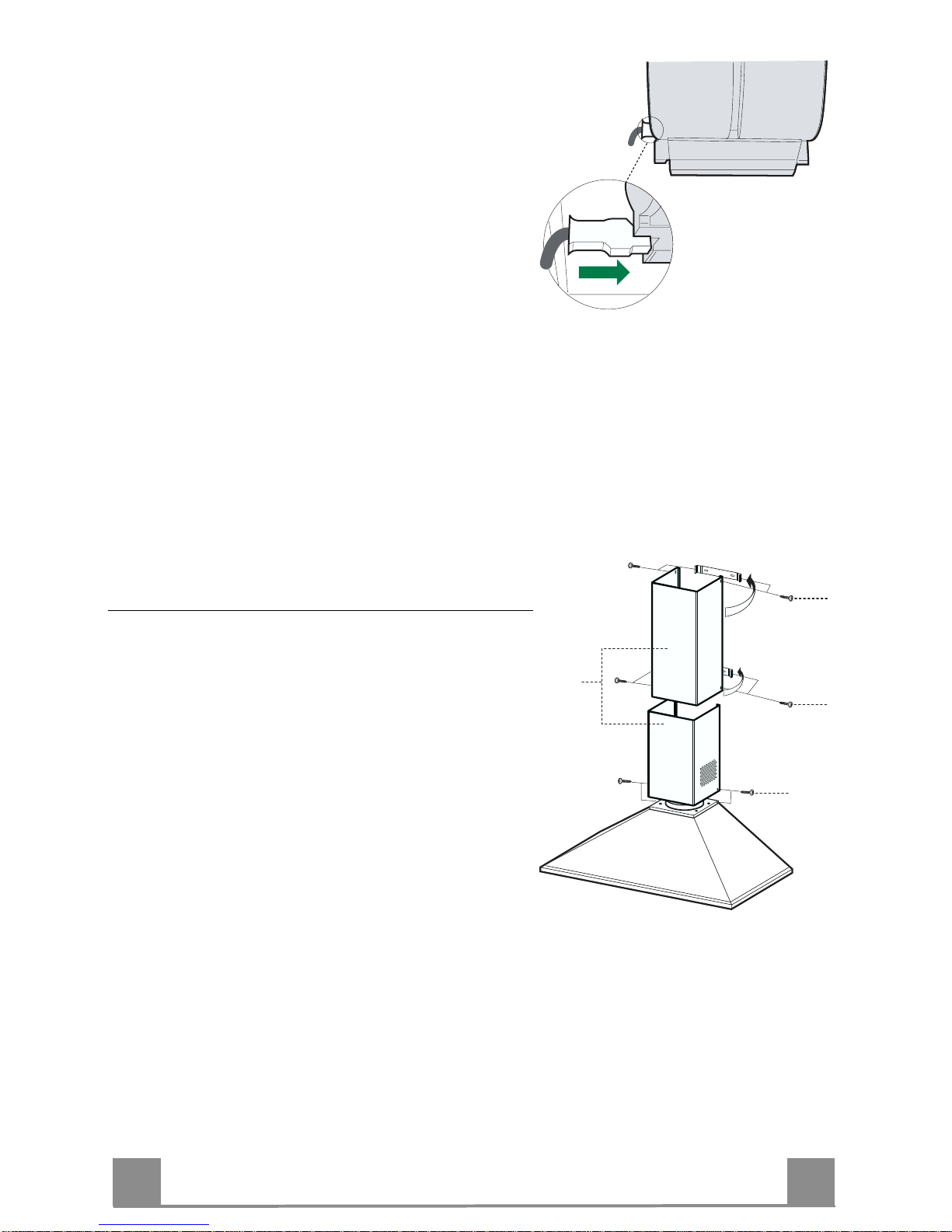
ELECTRICAL CONNECTION
• Connect the hood to the mains through a two-pole
switch having a contact gap of at least 3 mm.
• Remove the grease filters (see paragraph Maintenance) being sure that the connector of the feeding
cable is correctly insert ed in th e socket placed o n the
side of the fan.
Flue assembly
Upper exhaust flue
• Slightly widen the two sides of the upper flue and
hook them behind the brackets 7.2.1, making sure
that they are well seated.
• Secure the sides to the brackets using the 4 screws
12c (2,9 x 9,5) supplied.
Lower exhaust flue
• Slightly widen the two sides of the flue and hook
them between the upper flue and the wall, making
sure that they are well seated.
• Fix the lower part laterally to the hood body using
the 2 screws 12c (2,9 x 9,5) supplied.
• Make sure that the air outlet connection is aligned
with the chimney outlets.
12c
12c
12c
2.2
2.1
2
Page 19

EN
119
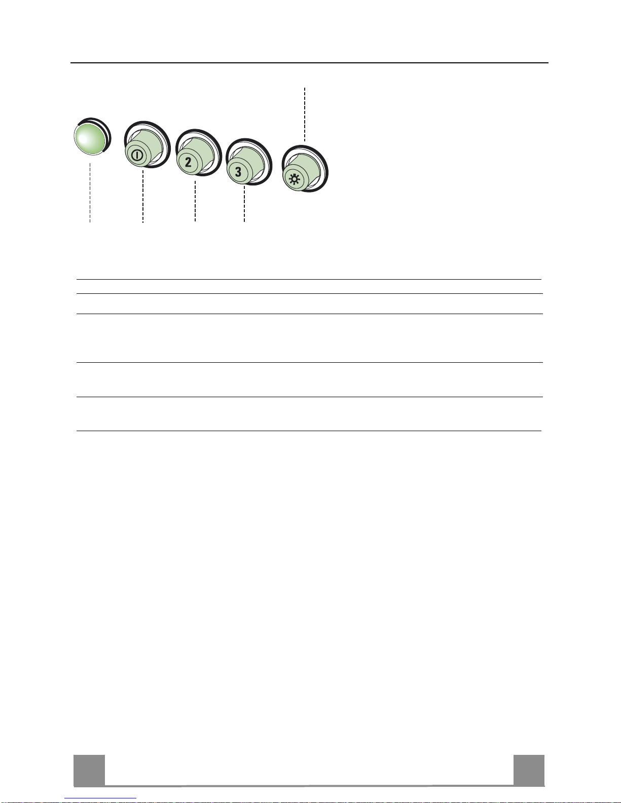
USE
L
V1 V2 V3
S
L Light Switches the lighting system on and off.
S Led Motor running led.
V1 Motor Switches the extractor motor on and off at low speed. Used to provide a
contin-uos and silent air change in the presence of light cooking vapours.
V2 Speed Medium speed, suitable for most operating conditions given the optimum
treated air flox/noise level ratio.
V3 Intensive Maximum speed, used for eliminating the highest cooking vapour emission,
including long periods.
Page 20

EN
220
MAINTENANCE
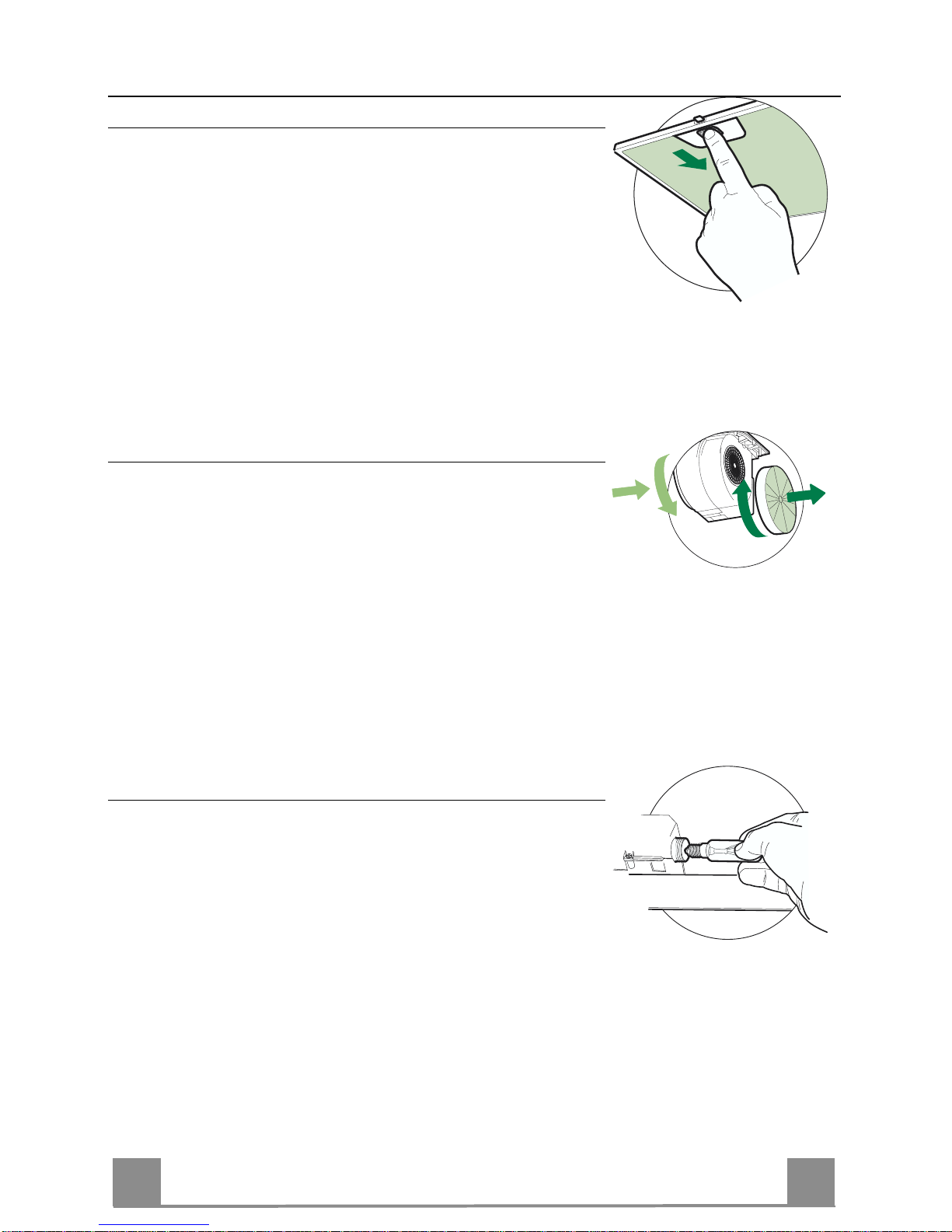
Grease filters
CLEANING METAL SELF- SUPPORTI NG GREASE FI LTERS
• The filters must be cleaned every 2 months of operation, or
more frequently for particularly heavy usage, and can be
washed in a dishwasher.
• Remove the filters one at a time by pushing them towards
the back of the group and pulling down at the same time.
• Wash the filters, taking care not to bend them. Allow them
to dry before refitting.
• When refitting the filters, make sure that the handle is visible
on the outside.
Activated charcoal filter (Recirculation version)
These filters are not washable and cannot be regenerated, and
must be replaced app roximately every 4 months of op eration, or
more frequently with heavy usage.
REPLACING THE ACTIVATED CHARCOAL FIL T ER
• Remove the metal grease filters
• Remove the saturated activated charcoal filter as shown (A).
• Fit the new filters (B).
• Replace the metal grease filters.
A
B
Lighting
LIGHT REPLACEMENT
40 W incandescent lig ht.
• Remove the metal grease filters.
• Unscrew the bulb s and replace th em with new ones h aving the
same characteristics.
• Replace the metal greas e filters.
Page 21

FR
221
CONSEILS ET SUGGESTIONS
INSTALLATION
• Le fabricant décline toute responsabilité en cas de dommage dû à
une installation non correcte ou non conforme aux règles de l’art.
• La distance minimale de sécurité ent re le plan de cuisson et la ho tte
doit être de 650 mm au moins.
• Vérifier que la tens ion du s ect eu r cor respond à l a v aleur qui fi gu re sur
la plaquette apposée à l’intérieur de la hotte.
• Pour les Appareils appartenant à la Ière Classe, veiller à ce que la
mise à la terre de l’installation électrique domestique ait été effectuée
conformément aux normes en vigueur.
• Connecter la hotte à la sortie d’air aspiré à l’aide d’une tuyauterie d’un
diamètre égal ou supé rieur à 120 mm. Le parcours de la tuyauterie
doit être le plus court possible.
• Eviter de connecter la hotte à des conduites d’évacuati on de fumées
issues d’une combustion tel que (Chaudière, cheminée, etc…).
• Si vous utilisez des appareils qui ne fonctionnent pas à l’électricité
dans la pièce ou est installée la hotte (par exemple: des appareils
fonctionnant au gaz), vous devez prévoir une aération suffisante du
milieu. Si la cuisine en est dépourvue, pratiquez une ouverture qui
communique avec l’extérieur pour garantir l’infiltration de l’air pur.
UTILISATION
• La hott e a été conçue exclusiv ement pour l’usage domestique, dans
le but d’éliminer les odeurs de la cuisine.
• Ne jamais utiliser abusivement la hotte.
• Ne pas l aisser les flammes libres à forte intensité quand l a hotte est
en service.
• Toujours régl er les flammes de manière à éviter toute sortie l atérale
de ces dernières par rapport au fond des marmites.
• Contrôler les friteuses lors de l’utilisation car l’ huile surchauffée pourrait s’enflammer.
• Ne pas pr éparer d’aliments flambés sous la hotte de cuisine : risque
d’incendie
• La hotte ne doit pas être utilisée par des enfant s ou des personnes ne
pouvant pas assurer une utilisation correcte.
ENTRETIEN
• Avant de procéder à toute opération d’entretien, retirer la hotte en
retirant la fiche ou en actionnant l’interrupteur général.
• Effectuer un entretien scrupuleux et en temps dû des Filtres, à l a cadence conseillée.
• Pour le nettoyage des surfaces de la hotte, il suffit d’utiliser un chiffon
humide et détersif liquide neutre.
650 mm min.
Page 22

FR
222
CARACTERISTIQUES
Encombrement
Composants
Réf. Q.té Composants de Produit
1 1 Co rps Ho tte équipé de : Command es, Lumiè re, Groupe
Ventilateur, Filtres
2 1 Cheminée Télescopique formée par :
2.1 1 Cheminée Supérieure
2.2 1 Cheminée Inférieure
9 1 Flasque de Réduc ti on ø 150-1 2 0 mm
15 1 Raccord Sortie Air
Réf. Q.té Composants pour l’installation
7.1 2 Brides Fixation Corps Hotte
7.2.1 2 Brides Fixation Cheminée Supérieure
11 8 Chevilles
12a 8 Vis 4,2 x 44,4
12c 6 Vis 2,9 x 9,5
12d 2 Vis M4 x 25
Q.té Documentation
1 Manuel d’instructions
1
12c
12c
12c
2.1
2.2
2
7.2.1
12a 11
7.1
12a 11
12d
15
9
Page 23

FR
223
INSTALLATION
Perçage Paroi et Fixation Brides
Tracer sur la paroi:
• une ligne verticale allant jusqu’au plafond ou à la limite supérieure, au centre de la zone
prévue pour le montage de la hotte;
• une ligne horizontale à 650 mm min. au-dessus du plan de cuisson pour installation sans
embases: à la cote H (H=haut eur de la p artie en vu e de l’e mbase), en cas d’ install ation avec
embase.
• Poser comme indi qué une b ride 7.2.1 sur la paroi à 1-2 mm du plafond ou de la limite supérieure, en alignant son centre (découpes) sur la ligne verticale de repère.
• Marquer les centres des trous rainurés de la bride.
• Poser comme indiqué la bride 7.2.1 à X mm sous la première brid e (X = hauteur ch eminée
supérieure fournie), en alignant son centre (découpes) sur la ligne vert i cale de repère.
• Marquer les centres des trous rainurés de la bride.
• Poser comme indiqué, la bride 7.1 à 95 mm de la ligne verticale de repère, et 210 mm audessus de la ligne horizontale de repère.
• Marquer les centres des trous de la bride.
• Répéter cette opération sur le côté opposé.
FIXATION EMBASE (SI FOURNIE)
L’Embase doit être montée avant d’installer le corps de la hotte et si l’on souhaite la fixer au
mur par lehaut ou par le bas, il est nécessaire de la monter à la juste hauteur avant de monter
les bases. Comme il s’agit d’une opération complexe, elle doit être confiée à l’installateur de la
cuisine ou à un personnel compéten t ayant pris conn aissance de toutes les d imensions finales
des meubles.
En se limitant à la fixation supérieure, procéder comme suit :
• Poser l’embase su r la b ase en i nséran t l’i ntercal aire in férieur en tre l e plan sup érieu r et la p aroi, en le centrant par rapport à la ligne verticale de repère.
• Marquer les centres des deux trous de l’intercalaire supérieur.
• Percer de ø 8 mm tous les points marqués.
• Insérer les chevilles 11 dans les trous.
• Fixer les brides en utilisant les vis 12a (4,2 x 44,4) fournies.
• Si présente, fixer l’embase, en utilisant les vis 12a (4,2 x 44,4) fournies.
H
X
1÷2
650 min.
7.2.1
7.1
95
95
210
Page 24

FR
224
Montage Corps Hotte
• Visser su r les brides 7.1 les 2 vis 12d fournies.
• Accrocher le corps hotte aux brides 7.1, en le centrant sur la
ligne verticale.
• Agir sur les vis 12d, par le dessous de la hotte pour en niveler
le corps.
7.1
12.d
Branchements
SORTIE AIR VERSION ASPIRANTE
En cas d’install ation en version aspirante, brancher la ho tte à la
tuyauterie de sortie via un tube rigide ou flexible de ø 150 ou 120
mm, au choix de l’installateur.
• En cas de branchement avec un tube de ø120 mm, insérer le
flasque de réduction 9 sur la sortie du corps de la hotte.
• Fixer le tube par des colliers appropriés. Le matériau nécessaire n’est pas fourni.
• Retirer les éventuels filtres anti-odeur au charbon actif.
ø 120ø 150
9
SORTIE AIR VERSION FILTRANTE
• Appliq uer par pression le raccord sortie air 15 sur
la sortie du corps de la hotte.
• S’assurer de la présence des filtres anti-odeur au
charbon actif.
15
Page 25

FR
225
BRANCHEMENT ELECTRIQUE
• Brancher l a hotte sur le secteur en in terposant un interrupteur bipol aire avec ouverture des contacts d ’au
moins 3 mm.
• Enlever les filtres à graisse (voir § "Entretien") et
s'assurer que le connecteur du câble d'alimentation
soit bien branché dans la prise du diffuseur.
Montage Cheminée
Cheminée supérieure
• Elargir légèrement les deux bords latéraux, et les accrocher derrière les brides 7.2.1 ; refermer jusqu’à la
butée.
• Fixer latéralement aux brides, à l’aide des 4 vis 12e
(2,9 x 9,5) fournies.
Cheminée inférieure
• Elargir légèrement les deux bords latéraux de la Cheminée et les accrocher en tre la Cheminée supérieure
et la paroi; refermer jusqu’à la butée.
• Fixer latéralement la partie inférieure aux bagues prévues à cet effet, à l’ai de des 2 vis 12c fournies.
• S’assurer également qu’elles soient bien insérées
dans les raccord 15.
12c
12c
12c
2.2
2.1
2
Page 26

FR
226
UTILISATION
L
V1 V2 V3
S
L Lumières Allume et éteint l’installation de l’éclairage.
S Del Del allumage Moteur.
V1 Moteur Met en marche et à l’arrêt le moteur aspiration à vitesse minimale, pour un
rechange d’air permantent particulièrement silencieux en cas de faibles vapeurs de cuisson.
V2 Vitesse Vitesse moyenne pour la plupart des conditions d’utilisation, étant donné le
rapport optimal entre débit d’air traité et niveau sonore.
V3 Vitesse Vitesse maximum, pour faire face aux émissions maximum de vapeur de
cuisson, même pendant des temps prolongés.
Page 27

FR
227
ENTRETIEN
Filtres anti-graisse
NETTOYAGE FILTRES ANTI-GRAISSE METALLIQUES AUTOPORTEURS
• Lavables au lave-vaisselle, ils doivent être lavés environ tous
les 2 mois d’emploi ou plus fréquemment en cas d’emploi particulièrement intense.
• Retirer les filtres l’un aprés l’autre, en les poussant vers la partie arrière du groupe et en tirant simultanément vers le bas.
• Laver les filtres en évitant de les plier et les laisser sécher avant
de les remonter.
• Remonter les filtres en veillant à ce que la poignée reste vers la
partie visible externe
Filtre anti-odeur (Version filtrante)
Il ne sont pas lavables ni régénérables, il faut les remplacer au
moins tous les 4 mois d’emploi ou plus fréquemment en cas
d’emploi particulièrement intense.
REMPLACEMENT FILTRE AU CHARBON ACTIF
• Retirer les filtres anti-graisse métalliques.
• Retirer les filtres anti-odeur au charbon actif saturés, comme
indiqué (A).
• Monter les nouveaux filtres (B).
• Remonter le filtres anti-graisse métalliques.
A
B
Eclairage
REMPLACEMENT LAMPES
Lampes à incandescence de 40 W
• Retirer les filtres anti-graisse métalliques.
• Dévisser les l ampes et les remplacer par de nou velles avec les
mêmes caractéristiques.
• Remonter les filtres anti-graisse métalliques.
Page 28

DE
228
EMPFEHLUNGEN UND HINWEISE
MONTAGE
• Das Gerät darf nur vom Fachpersonal angeschlossen werden.
• Der Herstel ler haftet nicht für Schäden, die auf ei ne fehlerhafte und
unsachgemäße Montage zurückzuführen sind.
• Der minimale Sicherheitsabstand zwischen Kochmulde und Haube
muss 650 mm betragen.
• Prüfen, ob die Netzspannung mit dem Wert auf dem im Haubeninneren angebra chten Schild übereinstimmt .
• Bei Geräten der Klasse I ist sicherzus tellen, dass die elektrisc he Anlage des Wohnhauses über eine vorschriftsmäßige Erdung verfügt.
• Das Anschlussrohr der Haube zur Luftaustrittsöffnung sollte möglicherweise einen Durchmesser von 1 50 mm aufweisen. Der Rohrverlauf muss so kurz wie möglich sein.
• Die Haube darf an keine Entlüftungs s chächte angeschl ossen werde n,
in die Verbrennungsgase (Heizkessel, Kamine usw.) geleitet werden.
• Werden im Raum außer der Dunsta bzugshaube andere, nicht elektrisch betriebene (z.B. gasbe triebene) Geräte verwend et, muss für eine ausreichende Belüftung ges orgt werden. Sollte die Küche di esbezüglich nicht entsprechen, i st an einer Aussenwa nd eine Öffnung anzubringen, die Frischluftzufuhr gewährleistet.
BEDIENUNG
• Die Dunstabzugshaube ist ausschließlich zum Einsatz im privaten
Haushalt und zur Beseitigung von Küchengerüchen vorgesehen.
• Bei unsachgemäßer Benutzung wird keine Haftung übernommen.
Achtung! Große Flammen bei eingeschalteter Haube niemals
unbedeckt lassen.
• Die Intensivität der F lamme ist s o zu reguliere n, dass si e den Topfboden nicht überragt.
Achtung! Frittiergeräte müssen während des Gebrauchs stets
beaufsicht igt werden: Überhitztes Öl kann sich entzünden.
• Keine flambierten Speisen unter der Abzugshaube zubereiten:
Brandgefahr.
• Die Dunstabzugshaub e darf v on Ki ndern oder Pe rsonen, die hinsi chtlich der Bedienung nicht unterwiesen wurden, keinesfalls verwendet
werden.
WARTUNG
• Bevor Wartungsarbeiten durc hgeführt werden, muss die Stromzufuhr
zur Haube unterbrochen werden, indem der Stecker gezogen oder
der Hauptschalter abgeschaltet wird.
• Bei der Filterwartung müssen die vom Hersteller empfohlenen Zeiträume zum Austauschen der Filter genauestens eingehalten werden.
• Zur Reinigung der Haubenflächen Wir empfehlen ein feuchtes Tuch
und ein mildes Flüssigreinigungsmittel.
• Bitte kei ne Reinigungsmittel mit Scheuermittel verwende n. Die Oberfläche wird damit verkratzt.
650 mm min.
Page 29

DE
229
CHARAKTERISTIKEN
Platzbedarf
Komponenten
Pos. St. Produktkomponenten
1 1 Haubenkörper mit Schaltern, Beleuchtung, Gebläse-
gruppe, Filtern
2 1 Teleskopkamin bestehend aus:
2.1 1 oberer Kaminteil
2.2 1 unterer Kaminteil
9 1 Reduzierfl ansch ø 150-120 mm
15 1 Luftaustritt-Anschlussstück
Pos. St. Montagekomponenten
7.1 2 Befestigungsbügel Haubenkörper
7.2.1 2 Befestigungsbügel oberer Kaminteil
11 8 Dübel
12a 8 Schrauben 4,2 x 44,4
12c 6 Schrauben 2,9 x 9,5
12d 2 Schrauben M4 x 25
St. Dokumentation
1 Bedienungsanleitung
1
12c
12c
12c
2.1
2.2
2
7.2.1
12a 11
7.1
12a 11
12d
15
9
Page 30

DE
330
MONTAGE
Bohren der Befestigungslöcher und Fixieren der Befestigungsbügel
Achtung: Bitte beacht en Sie bei der Montage das Gewicht der komplet ten Haube. Die Tragfähig -
keit der Decke oder alternativ der Trägerplatte für diese Zugbelastung muss vor der Montage geprüft und gegebenenfalls durch die Anbringung von geeigneten Befestigungs- oder Stabilisierungselementen hergestellt werden. Kann eine hinreichende Tragfähigkeit nicht sichergestellt
werden, ist von einer Montage abzusehen.
Nachstehende Linien an die Wand zeichnen:
• eine vertikale Linie bis zur Decke oder oberen Begrenzung, un d zwar in der Mitte des Bereiches, in dem
die Haube montiert werden soll;
• eine horizontale Linie: mit einem minimalen Abstand von 650 mm zur Kochfläche bei Montage ohne
Rückwand paneel; mit e inem Absta nd H (H= H öhe des sichtbar en Teils des Rückwand paneels) be i Montage mit Rückw andpane e l.
• Einen Bügel
7.2.1
zirka 1-2 m m unter de r Decke ode r obere n Begrenz ung an di e Wand le gen und se inen
Mittelpunkt (Einschnitte) auf die vertikale Bezugslinie ausrichten.
• Die Mitte der beiden Bügellöcher an der Wand markieren.
• Den zweiten Bügel
7.2.1
an die Wand legen, w obei ei n Absta nd X mm v om obe ren B ügel e inzu halten i st
(X = Höhe des jeweiligen o beren Kam inteils); den Mittel punkt (Ein schnitte) auf die vertikale Bez ugslinie
ausrichten.
• Die Mitte der Bügellöcher an der Wand markieren.
• Einen der beiden Bügel
7.1
95 mm von der vertikalen Bezugslinie und 210 mm oberhalb der
horizontalen Bezugslinie auflegen.
• Die Mittelpunkte der Bügelbohrunge n an der Wand markieren.
• Gle i c hermaßen a n de r ge genüberli egenden Se it e vorgehen.
RÜCKWANDPANEEL (OPTION)
Das Rückwandpaneel wird vor der Dunstabzugshaube montiert; falls es sowohl an der Ober- wie auch Unterseite be festigt w erden so ll, muss es vor Monta ge der U nterschr änke i n korrekte r Höhe fi xiert wer den. Da
es sich hierbei um einen komplexen Arbeitsschritt handelt, muss dieser Vorgang vom Kücheninstallateur
bzw. auf jeden Fall von erfahrenem Personal durchgeführt werden, das die Endmaße der Küchenmöbel
kennt.
Wird das Rückwandpaneel nur oben fixiert, ist wie nachstehend vorzugehen:
• Das Paneel auf de n Unterschr ank stellen und de n unteren Ra nd zwischen Ar beitsfläc he und Wand schie ben, wobei die Rückwand auf die vertikale Bezugslinie auszurichten ist.
• Die Bohrungen an der oberen Kante kennzeichnen.
• Mi t einem Bohrer ø 8 mm die markie r t e n P u nkte bohren.
• Die Dübel
11
in die Bohrun ge n einfügen.
• Die B ügel mit den mi tgeliefe r te n S chrauben
12a
(4,2 x 44,4) fixieren.
• Falls ein Rückwandpaneel vorha nden ist, dieses mi t den mitgelieferten Schrauben
12a
(4,2 x 44,4) fixieren.
H
X
1÷2
650 min.
7.2.1
7.1
95
95
210
Page 31

DE
331
Montage des Haubenkörpers
• Bei den Bügeln 7.1 die 2 mitgelieferten Schrauben 12d ein-
schrauben.
• Den Haubenkörper bei den Haltebügeln 7.1 einhängen und auf
die vertikale Linie ausrichten.
• Mit Hilfe der Schrauben 12d vom Haubenunteren her den
Haubenkörper ausrichten.
7.1
12.d
Anschluss der Abluftversion
Bei Abluftbetrieb kann die Haube vom Installateur wahlweise
mittels Rohr oder Schlauch (ø 150 oder 120 mm) an die Außenrohrleitung angeschlossen werden.
• Bei Verwendung eines Anschlussrohres ø 120 den Reduzierflansch 9 am Haubenaustritt anbringen.
• Das Rohr mit geeigneten Rohrschellen fixieren. Das hierzu
erforderliche Material wird nicht mitgeliefert.
• Eventuell vorhandene Aktivkohlefilter entnehmen.
Achtung! All e Querschnittänderungen oder Ri chtungsän-
derunge n des A bluftka nals r eduzier en die L eistu ng der H aube.
ø 120ø 150
9
ANSCHLUSS IN UMLUFTVERSION
• Das Anschlussstück 15 beim Luftaustritt des Haubenkörpers
eindrücken.
• Sicherstellen, dass der Aktivkohle-Geruchsfilter vorhanden ist.
15
Page 32

DE
332
Elektroanschluss
Vor der Installation die Netzspannung durch her-
ausdrehen der Sicherung oder ausschalten des
Hauptschalters stromlos machen.
• Bei Anschluss der Haube an das Stromnetz muss
ein zweipoliger Schalter mit einem Öffnungsweg
von mindestens 3 mm zwischengeschaltet werden.
• Entfernen Sie die Fettfilter (s. Abschnitt „War-
tung“) und versichern Sie sich, daß die Kabelverbindung in die Steckdos e des Gebläses einwandfrei
eingesteckt wird.
Achtung: Das Gerät nur an die Netzspannung die im
Typenschild a ngegeben ist anschließen.
Kaminmontage
Oberer Kaminteil
• Die beiden seitlichen Schenkel leicht auseinanderbiegen, hinter den Bügeln 7.2.1 einhängen und bis
zum Anschlag wieder schließen.
• Bei den Bügeln mit Hilfe der 4 mitgelieferten
Schrauben 12e (2,9 x 9,5) fixieren .
Unterer Kaminteil
• Die beiden seitlichen Schenkel des Kaminteils leicht
auseinanderbiegen, zwischen dem oberen Kaminteil
und der Wand einhängen und bis zum Anschlag wieder schließen.
• Den unteren Kaminteil an der Seite bei den entsprechenden Buchsen mit 2 der mitgelieferten Schrauben
12c fixieren.
• Sicherstellen, dass sie korrekt beim LuftaustrittAnschluss 15 eingerastet sind.
12c
12c
12c
2.2
2.1
2
Page 33

DE
333
BEDIENUNG
L
V1 V2 V3
S
L Beleucht. Schaltet die Beleuchtung ein und aus.
S Led Betriebsanzeigelampe.
V1 Motor Schaltet den Gebläsemotor mit minimaler Geschwindigkeit ein oder aus.
Diese Stufe ist für einen ständigen und besonders leisen Luftaustausch bei
geringer Kochdunstentwicklung geeignet.
V2 Geschw. Mittlere Gebläsestufe, eignet sich aufgrund des guten Verhältnisses zwi-
schen Fördervolumen und Geräuschentwicklung für die meisten Anwendungssituationen.
V3 Geschw. Höchste Gebläsestufe, eignet sich für starke Kochdunstentwicklung, auch
über längere Zeit hin.
Page 34

DE
334
WARTUNG
Fettfilter
SELBSTTRAGENDER METALLFETTFILTER R EINIGUNG
• Sie müssen nach 2-monatigem Betrieb bzw. bei starkem
Einsatz auch häufiger gereinigt werden, was im Geschirrspüler möglich ist.
• Die Filter nacheinander aushaken, indem sie auf die Rückseite der Gruppe geschoben und gleichzeitig nach unten gezogen werden.
• Die Filter reinigen (darauf achten, sie nicht zu verbiegen)
und vor der Remontage trocknen lassen.
• Bei der Remontage ist darauf zu achten, dass sich der Griff
auf der sichtbaren Außensei t e befindet.
Geruchsfilter (Umluftversion)
Sie können weder gewaschen noch wiederverwendet werden und
sind alle 4 Betriebsmonate bzw. bei starkem Einsatz auch häufiger auszutauschen.
AUSTAUSCHEN DER AKTIVKOHL E FIL T ER
• Die Metallfettfilter entnehmen.
• Den gesättigten Aktivkohle-Geruchsfilter wie gezeigt entfernen (A).
• Die neuen Filter wie gezeigt montieren (B).
• Die Metallfettfilter wieder montieren.
• Die Kohlefilter können mit dem Hausmüll entsorgt werden.
A
B
Beleuchtung
AUSWECHSELN DER LAMPEN
Glühlampen 40W
• Die Metallfettfilter entfernen.
• Die Lampen ausschrauben un d durch gleichwertige ersetzen.
• Die Metallfettfilter wieder montieren.
Page 35

TR
335
TAVSIYELER VE ÖNERILER
MONTAJ
• Yalnιş veya eksik montajdan doğan herhangi bir zararιn sorumlulu ğu
üreticiye ait değildir.
• Davlumbaz ile pişirici cihazιn ocak kιsmι arasιndaki minimum güvenlik
mesafesi 650 mm.dir.
• Besleme voltajιnιn, davlumbaz içerisine yerleştirilen bilgi etiketinde
belirtilenle aynι olup olmadιğιnι kontrol edin.
• Sιnιf I elektrikli aletleri için, güç kaynağιnιn yeterli topraklamayι
sağlayιp sağlamadιğιnι kontrol edin. Minimum 120 mm çapιnda bir
boru yoluyla davlumbazι çιkιş bacasιna bağlayιn. Baca bağlantιsι
mümkün oldu- ğunca kιsa olmalιdιr.
• Davl umbaz borusunu yanιcι duman taşιyan bac a deliğine (buhar kazanι, şömine, vb.) bağlamayιn.
• Davlumbazιn elektrikle çalιşmayan aletlerle (örneğin; gazlι cihazlar)
bağιntιlι olarak kullanιlmamasι halinde çιkιş gazιnιn geri tepmesini
önlemek amacιyla odada yeterli bir havalandιrma
sağlanmalιdιr.Temiz hava gi rişini temin etmek için mutfakta doğrudan
dιşarιya açιlan bir açιklιk bulunmalιdιr.
KULLANIM
• Davlumbaz mutfaktaki kokularιn emilmesi amacιyla evlerde kull anιm
için tasarlanmιştιr.Ticari ve endüstriyel amaçlar için kullanmayιnιz.
• Davlumbazι tasarlandιğι amaçl arιn dιşιnda kesinlikle kullanmayιnιz.
• Davlumbaz çalιşιrken altιnda kesinlikle yüksek çιplak ateş
bιrakmayιn.
• Alev yoğunluğunu doğrudan tencerenin altιnda kalacak şekilde
ayarlayιn, kenarlarιnι sarmadιğιnd an emin olun.
• Yağda kιzartma tavalarιnι kullanιrken sürekli olarak takip edin: fazla
ιsιnan yağ tutuşabilir.
• Kapağın altında kıvılcımdan kaçının, yangın riski
• Davlumbaz çocuklar veya doğru kullanιm konusunda bi lgisi olmayan
kişiler tarafιndan kullanιlmamalιdιr.
BAKIM
• Herhangi bir bakιm işlemini gerçekleştirmeden önce davlumbazι
kapatιn veya fişini çιkarιn.
• Filtreleri belirtilen zamanlarda temizleyin ve / veya değiştirin.
• Cihazι nemli bir bez ve nötr bir sιvι deterjan kullanarak temizleyin.
650 mm min.
Page 36

TR
336
ÖZELLIKLER
Boyutlar
Parçaları
Rif. adet Ürün parçaları
1 1 Kumandalar, Işıklar ve Filtrlerle komple halde davlum-
baz gövdesi
2 1 Şunlardan oluşan telesko pik baca:
2.1 1 Üst Baca
2.2 1 Alt Baca
9 1 Redüksiyon Flanşı ø 150-120 mm
15 1 Hava Çıkış Rakoru
Rif. adet Montaj parçaları
7.1 2 Davlumbaz Gövdesi için Tesbit Braketleri
7.2.1 2 Üst Baca için Tesbit Braketleri
11 8 Dübeller
12a 8 Vidalar 4,2 x 44,4
12c 6 Vidalar 2,9 x 9,5
12d 2 Vidalar M4 x 25
adet Belgeler
1 Kullanım El Kitabı
1
12c
12c
12c
2.1
2.2
2
7.2.1
12a 11
7.1
12a 11
12d
15
9
Page 37

TR
337
MONTAJ
Duvar Delme İşlemi ve Braketlerin Sabitlenmesi
Duvara şunları çizerek işaretleyiniz:
• Tavana yada üst sınıra kadar uzanan dikey bir çizgi; bu davlumbazın monte edileceği alanın
tam ortasından geçmelidir.
• Setüstü ocağın 650 mm. üzerinden geçen yatay bir çizgi; b u, taban kısmı (zemin) olmadan
yapılan montaj içindir; H yüksekliği ise (H=tabanın görülen kısmının yüksekliği) tabanla
(zeminle) yapılacak montaj içindir.
• 7.2.1 no'lu braketi resimde görüldüğü gibi tavandan ve ya üst sı nı rdan 1- 2 mm mesa feye yerleştiriniz, merkezini (çentiklerin olduğu) referans alınan di key çizgiye merkezleyere k hizalayınız.
• Braket deli kleri nin merkezlerini duvara işaretleyiniz.
• 7.2.1 no'lu b raketi resimde gö rül düğü gibi birinci braketten X mm mesafeye yerleştiriniz (X
= Davlumbaz üst b acasın ın yüksekli ği, bunun da merkezini (çentiklerin olduğu) referans alınan dikey çizgi ye hizalayınız.
• Braket deli kleri nin merkezlerini duvara işaretleyiniz.
• 7.1 no'lu br aketi resimde görü ldüğü gibi dikey referans çizgisinden 95 mm mesafeye, yatay
referans çizgisinin üstünden de 210 mm mesafeye yerleştiriniz.
• Braket deli kleri nin merkezlerini duvara işaretleyiniz.
• Bu işlemi karşı tarafta da tekrarlayınız.
TABAN (İSTEĞE BAĞLI)
Taban (yada zemin) davlumbaz gövdesi monte edilmeden önce takılır ve hem üst hem de alt
noktasından duvara sabitlenmesi isteniyorsa, kaideler monte edilmeden önce doğru yüksekliğe
sabitlenir. Bu operasyon oldukça karmaşık olduğundan, sadece mutfak mont örü veya mutfak
mobilyalarının ölçülerini bilen vasıflı personel tarafından yapılmalıdır.
Eğer sadece üst tarafı sabitlenecekse şu şekilde hareket edilmelidir:
• Tabanı kaide üzerine yaslayınız ve alt çeperini duvar ile üzt yüzey arasına yerleştiriniz,
bu arada dikey referans çizgisine merkezlemeyi unutmayınız.
• Üst kenar çeperinin iki deliğini d uva ra işaretleyiniz.
• İşaretlenen yerlere ø 8 mm çapında delik açınız.
• 11 adet dübeli deliklere geçiriniz.
• 12a vidaları (4,2 x 44,4 ) kullanarak braketleri sabitleyiniz.
• Eğer mevcutsa tabanı (zemini) 12a vidaları (4,2 x 44,4) kullanarak sabitleyiniz.
H
X
1÷2
650 min.
7.2.1
7.1
95
95
210
Page 38

TR
338
Davlumbaz Gövdesi Montajı
• Braketleri (7.1) davlumbazla verilen , 2 adet vidayla (12d) vi-
dalayınız.
• Davlumbaz gövdesini dikey çizgiye merkezleyerek braketlere
7.1 takınız.
• Davlumbaz gövd esi sevi yesini a yarla mak için , davl umbazın alt
kısmından vidalara (12d) müdahale ediniz.
7.1
12.d
Bağlantılar
ASPİRATÖRLÜ MODEL HAVA ÇIKIŞI
Aspiratörlü modelin montajı için, davlu mbaz, montörü n seçeceği
150 yada 120 mm çapında sert veya esnek bir boru ile çıkış kanalına bağlanmalıdır.
• ø120 mm çapında boru ile bağlantı için, redüksiyon flanşını (9)
davlumbaz gövd esi çıkışına yerleştiriniz.
• Boruyu uygun kelepçelerle sıkarak sabitleyiniz. Bu malzeme
davlumbaz donanımıyla birlikte verilmemiştir.
• Varsa aktif karbonlu koku alma filtrelerini çıkarınız.
ø 120ø 150
9
FİLTRELİ MODEL HAVA ÇIKIŞI
• Hava Çıkış Rakorunu (15) davlumbaz gövdesi çıkışına
bastırarak takını z.
• Aktif karbonlu koku alma filtresinin mevcut olduğunu kontrol
ediniz.
15
Page 39

TR
339
ELEKTRİK BAĞLANTISI
• Davlumbazı şebe ke cereyanına bağlarken ara y temas
aralığı en az 3 mm olan çift kutu plu bir el ektri k anah tarı koyunuz.
• Yağ tutucu filtreleri çıkarınız (bakınız "Bakım" paragrafı) ve besleme kablosu soketinin aspiratör prizine iyice takılmış olduğundan emin olunuz.
Bacanın Montajı
Üst baca
• İki yan kenar çeperini hafifçe genişletiniz, braketlerin
(7.2.1) arkasına geçirip son noktasına kadar
bastırınız.
• Braketlere yan tarafından davlumbaz donanımındaki
4 adet vidayla 12c (2,9 x 9,5) sabitleyiniz.
Alt baca
• Bacanın iki yan kenar çeperini hafifçe genişletiniz,
üst baca ile du var arasına geçiriniz ve son noktasına
kadar bastırınız.
• Alt kısmını yan tarafından davlumbaz donanımındaki
2 adet vidayla 12c (2, 9 x 9,5) davlumbaz gövdesin e
sabitleyiniz.
• Rakor çıkışının (15) baca ağızlarına tekabül ediyor
olmasını kontrol ediniz.
12c
12c
12c
2.2
2.1
2
Page 40

TR
440
KULLANIM
L
V1 V2 V3
S
L Lambalar Aydınlatma sistemini yakar ve söndürür
S Led Motorun çalışmakta olduğunu bildiren led lambası
V1 Motor Aspiaratör motorunu minimum hızda açar ve kapatır ; mini mum hız sessi-
zce çalışarak aşırı pişirme buharı olmadığında sürekli hava dolaşımı sağlar.
V2 Hız Orta hız, kullanımın büyük kısmında yararlanılan hızdır, ses düzeyi ile hava
dolaşımı arasındaki oran optimumdur.
V3 Velocità Yüksek (maksimum) hız, uzun süreli olan ve çok fazla buhar açığa çıkaran
pişirme işlemlerinde kullanılmak içindir.
Page 41

TR
441
BAKIM
Yağ tutucu filtreler
METALİK YAĞ TUTU C U FİLTRELERİN TEMİZLENMESİ
• Bu filtreler bulaşık makinasında da yıkanabilir ve normal kullanıldıklarında iki ayda bir, yoğun kullanım halinde ise daha
sıkça yıkanmalarıı gereklidir.
• Filtrleri, grubun arka tarafından ittirerek ve aynı anda aşağı
doğru çekerek tek tek çıkarını z.
• Filtreleri yıkarken eğip katlamayınız, tekrar monte etmeden
önce de kurutunuz.
• Monte ederken kulpun görünen dış tarafa doğru gelmesine d ik-
kat ediniz.
Aktif karbonlu koku giderici filtreler (Filtreli Model)
Aktif karbonlu koku giderici filtre yıkanmaz ve rejenere edilmez,
normal kullanımda yaklaşık 4 ayda bir, yoğun kullanımda daha
sıkça değiştirilmesi gerekir.
DEĞİŞTİRİLMESİ
• Yağ tutucu filtreleri çıkarınız.
• Doyum noktasına ulaşmış aktif karbonlu koku giderici filtreleri
(A) şeklinde gösterildiği gibi çıkarınız
• Yeni filtreleri (B) şeklinde gösterildiği gibi takınız.
• Yağ tutucu filtreleri tekrar monte ediniz.
A
B
Aydınlatma
AMPULLERİN DEĞİŞTİRİLMESİ
40 W akkor lambalar
• Metalik yağ tutucu filtreleri çıkarınız.
• Ampulleri gevşetip çıkarınız ve aynı özelliklere sahip yenileriyle değiştiriniz.
• Metalik yağ tutucu filtreleri tekrar takınız.
Page 42

Page 43

Page 44

436002765_ver4
Il simbolo sul prodotto o sulla co nfezi on e indi ca che il prodo tto no n d eve ess ere c ons id era to co me un n ormal e r ifi uto dom es tic o,
ma deve ess ere port ato n el p unt o di rac c olta appr opri at o per i l r ic iclaggi o di appar ec chi atur e el ettri ch e ed el ettr oni ch e. Prov v ede ndo a
smaltire q ues to pro d otto i n m odo a ppro pri ato, s i contri bui sc e a evi t are p ote nzial i c onse gu enze nega tiv e per l’ ambi en te e p er la s alute,
che potrebbero deri v ar e da un o s m al ti m ento ina de guato del prodotto. P er i nformazio ni pi ù dettagli ate sul riciclaggio di questo prodotto,
contattare l’ufficio comunale, il servizio locale di smaltimento rifiuti o il negozio in cui è stato acquistato il prodotto.
The symbol on the product or on its pac kaging indi c a tes t ha t thi s pro duct may not b e tr e ated as hous e hol d w as te. Instea d i t s hal l
be handed ov er to the applicable c ollectio n point for the recyc ling of elec trical and electroni c equipm ent. By ensur ing this product is
disposed of correctly, you will help prevent potential negative consequences for the environment and human health, which could otherwise be caus ed by in appr opr iat e wast e han dli ng of this produc t. F or mor e detai led infor mati o n about recyc li ng of this produc t , ple ase
contact your local city office, your household waste disposal service or the shop where you purchased the product.
Le symbole sur le produit ou son em bal la ge in diqu e que c e pro d uit ne peut ê tre tr aité c omm e déc he t mén ager . Il d oit pl utôt être
remis au point de ramassage concerné, se chargeant du recyclage du matériel électrique et électronique. En vous assurant que ce
produit est él imi né correc temen t, vous favori sez l a préve ntion des conséq uenc es nég atives p our l’ envir onneme nt et la sa nté hum aine
qui, sinon, s er ai e nt l e r ésultat d’un traiteme nt inappropr i é d es d éc h ets d e c e produit. P our o bt enir plus de dé tai l s s ur l e rec yclage de ce
produit, veuillez prendre contact avec le bureau municipal de votre région, votre service d’élimination des déchets ménagers ou le
magasin où vo us av ez acheté le pro dui t.
Das Symbol auf dem Prod ukt oder seiner Verp acku ng weis t darauf hin, das s di eses Pro dukt n icht al s norm aler Haus halts abfal l
zu behand eln ist, s on der n an ein em S am mel pu nkt f ür das Recy cl ing v on elek tri sche n und elek troni sc he n Ger äte n ab geg ebe n w erde n
muss. Durc h Ihren Beitr a g zum korr ek te n Entsorge n dieses Pr odukts sc hützen Sie die Umwelt und die Ges u ndheit Ihr er M itmensch e n.
Umwelt und Gesundheit werden durch falsches Entsorgen gefährdet. Weitere Informationen über das Recycling dieses Produkts
erhalten Sie von Ihrem Rathaus, Ihrer Müllabfuhr oder dem Geschäft, in dem Sie das Produkt gekauft haben.
Ürün veya pak eti üzerindeki sembolü, bu ürünün normal bir evs el atık olarak görül memesi ve bu tip elektr ikli veya elektro nik
cihazları n atıldı ğı dönüşüm lü topl ama n oktal arına t erke dilm esi ger ektiğine işaret e der. B u ürünü g erekti ği gibi elim ine etm e kural ların a
uyarsanız çevre ve insan sağlığı üzerindeki olum suz etkilerini b ertaraf etmeye katk ı sağlamış olursunuz. B u ürünün geri d önüşüm
koşulları hakkında daha ayrıntılı bilgi için hudutları içinde bulunduğunuz belediyenin ilgili diaresine, atık yoketme servisine veya ürünün
satıcısına da nışınız.
Franke S.p.a.
Via Pignolini,2
37019 Peschiera del Garda (VR)
www.franke.it
73/23/CEE
Dir. 89/336/CEE
93/68/CEE
 Loading...