

Page 1

Instructions for use and installation
Cooker Hood
Istruzioni per l’uso e l’installazione
Cappa
Mode d’emploi et installation
Hotte de Cuisine
Bedienungsanleitung und Einrichtung
Dunstabzugshaube
Kullan
ım ve montaj talimatları
Davlumbaz
FDL 6065
FDL 9065
GB
IT
FR
DE
TR
Page 2

2
2
INDICE
AVVERTENZE - COMPONENTI............................................................................................................................................3
INSTALLAZIONE....................................................................................................................................................................4
USO - MANUTENZIONE........................................................................................................................................................5
INDEX
WARNINGS - COMPONENTS...............................................................................................................................................6
INSTALLATION ......................................................................................................................................................................7
USE - MAINTENANCE...........................................................................................................................................................8
SOMMAIRE
ATTENTION - COMPOSANTS...............................................................................................................................................9
INSTALLATION ....................................................................................................................................................................10
UTILISATION - ENTRETIEN................................................................................................................................................11
INHALTSVERZEICHNIS
HINWEIS - KOMPONENTEN...............................................................................................................................................12
MONTAGE............................................................................................................................................................................13
BEDIENUNG - WARTUNG..................................................................................................................................................14
IÇERIKLER
UYARILAR - PARÇALARI....................................................................................................................................................15
MONTAJ...............................................................................................................................................................................16
KULLANIM - BAKIMI VE TEMİZLENMESİ...........................................................................................................................17
IT
EN FR DE TR
Page 3
IT
3
3
AVVERTENZE - COMPONENTI
AVVERTENZE
- La dista nza minima tra il piano di cottura e la parte inferiore della cappa deve essere almeno di
650mm.
- Osservare le seguenti istruzioni riguardanti il funzionamento della cappa quando l'aria viene
convogliata verso l'esterno. (utilizzo aspirante)
- Deve essere prevista un'adeguata areazione del locale quando la cappa o apparecchi alimentati
con energia diversa da quella elettrica vengono usati contemporaneamente; la pressione negativa
della stanza non deve superare 4 Pa (4x10
-5
bar).
- L'aria raccolta non deve essere convogliata in un condotto usato per lo scarico dei fumi di apparecchi alimentati con energia diversa da quella elettrica.
- Rispettare le prescrizioni delle Autorità competenti relative allo scarico dell'aria da evacuare.
- Evitare la presenza di fiamma libera nello spazio sottostante la cappa.
- La cappa è sta ta costruita co n isolamento in Cl asse II per tanto non nece ssita di co nnessione a terra.
- Prima di effettuare tutte le operazioni di manutenzione scollegare l'apparecchio dall'alimentazione elettrica.
- Questo apparecchio non deve essere utilizzato da persone (bambini inclusi) con ridotte capacità
psichiche, sensoriali o mentali, oppure da persone senza esperienza e conoscenza, a meno che non
siano controllati o istruiti all’uso dell’apparecchio da persone responsabili della loro sicurezza.
- I bambini devono essere supervisionati per assicurarsi che non giochino con l’apparecchio.
ALLACCIAMENTO DEL CAVO DI ALIMENTAZIONE ALLA RETE
Prima dell'installazione verificare che la tensione della rete indicata sull'apposita targhetta applicata all'int erno dell'apparecchio , corrisponda alla tensi one della vostra abitazi one. Nel caso
in cui la Cappa non fosse provvista di spina, montare sul cavo alimentazione una spina normalizzata per il carico i ndicato sulla targhetta caratteristiche; nel caso di collegamento elettr ico
diretto alla rete è necessario interporre tra l'apparecchio e la ret e un i nterruttore omnipolare con
apertura minima tra i contatti di 3mm, dimensionato al carico e rispondente alle norme in vigore.
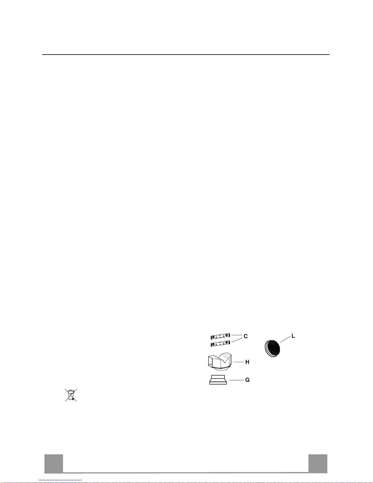
COMPONENTI
- 2 staffe di fissaggio C
- 1 flangia di riduzione G
- 1 raccordo filtrante H
- 2 filtri al carbone attivo L (facoltativo)
Il simbolo
sul prodott o o sull a co nfezi on e indi ca che il prodo tto no n dev e ess ere c ons id era to co me un n ormal e r ifi uto dom es tic o,
ma deve ess ere port ato n el p unt o di rac c olta appr opri at o per i l r ic iclaggi o di appar ec chi atur e el ettri ch e ed el ettr oni ch e. Prov v ede ndo a
smaltire q ues to pro d otto i n m odo a ppro pri ato, s i contri bui sc e a evi t are p ote nzial i c onse gu enze nega tiv e per l’ ambi en te e p er la s alute,
che potrebbero derivare da uno smaltimento inadegu ato del prodot to. Per informazi o ni più dettagl i ate sul ricicl aggi o di questo prodotto,
contattare l’uff icio comunale, il servizio locale di smaltimento rifiuti o il negozio in cui è stato acquistato il prodotto.
Page 4

IT
4
4
INSTALLAZIONE
La cappa deve essere montata al centro del piano cottura. La distanza minima tra il piano di
cottura e la superficie inferiore della cappa deve essere di 650mm.
Per il montaggio della cappa procedere nel modo seguente:
1) Prati care n°6 fori (X1-X2-J) Ø 8mm rispettando le quote indicate in fig. 1.
2) Per i vari montaggi utilizzare le viti e i tasselli espansione in dotazione.
3) Bloccare le staffe C (fig. 2) alla parete nei fori X1-X2.
4) Fissare la cappa alla parete nei fori esterni J1 e J2 (fig. 3).
5) Montaggio ASPIRANTE o FILTRANTE:
• ASPIRANTE
Per installazione in Versione Aspirante collegare la Cappa alla tubazione di uscita per mezzo
di un tubo rigido o flessibile di ø150 o 120 mm, la cui scelta è lasciata all'installatore.
• Per collegamento con tubo ø120 mm, inserire la Flangia di riduzione 9 sull’Uscita del
Corpo Cappa.
• Fissare il t ubo con adeguate fascette stringitubo. Il materiale occorrente non è in dotazione.
• Togliere eventuali Filtri Antiodore al Carbone attivo.
• FILTRANTE (VERSIONE OPZIONALE)
- Inserire il Raccordo filtrante H (fig. 6).
- Montare i filtri carbone attivo L (fig. 7) bloccarli ruo tando in senso o rario (circa 10 °) fino
allo scatto di arresto. Per lo smontaggio eseguire le operazioni all'inverso.
Montaggio Camini
6) Fissare il camino superiore A (fig. 8) alle staffe C (fig. 2/ fig. 8) utilizzando n°4 viti autofi-
lettanti Ø2,9mm in dotazione. La distanza tra i fori di fissaggio X1 e X2 viene stabilita dall'altezza del camino superiore H .
7) Applicare frontalmente il camino inferiore B (fig. 9) allargando leggermente le due parti
laterali e poi inserirlo nella cappa (fig. 9).
Page 5
IT
5
5
T2
T1
L
T3
USO - MANUTENZIONE
USO
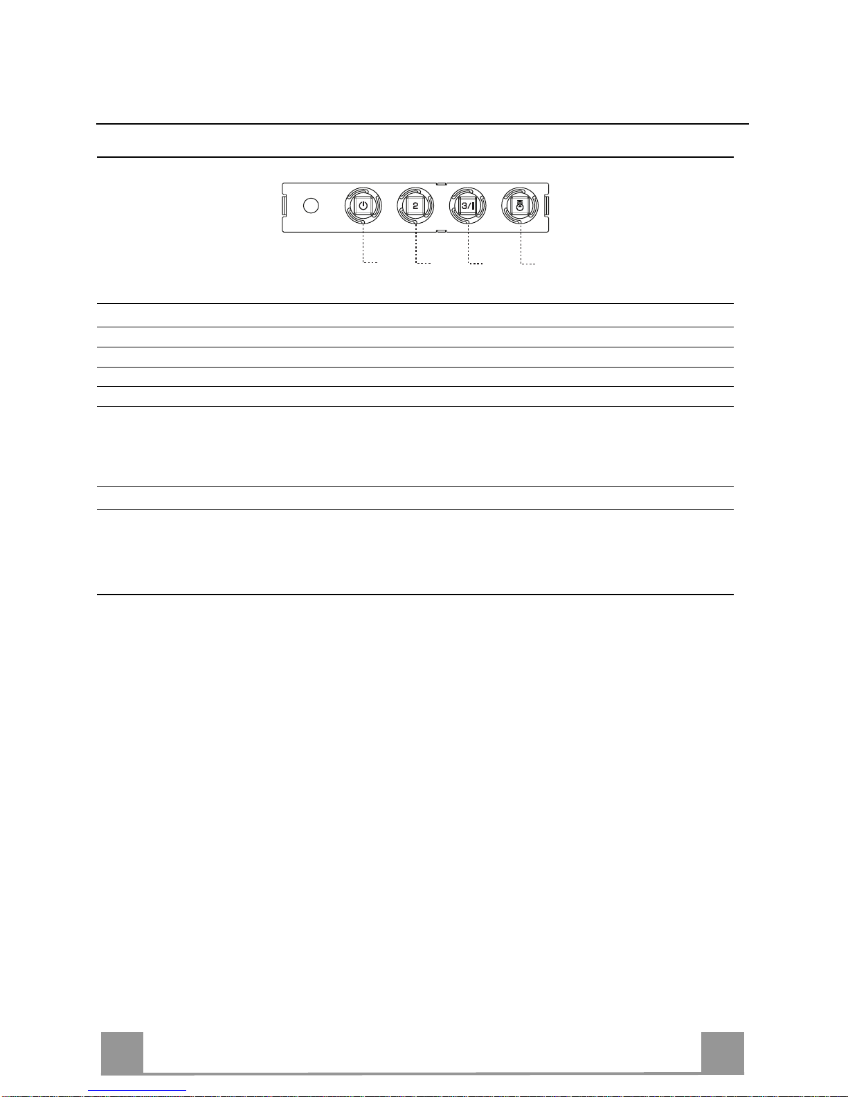
Quadro comandi
TASTO LED FUNZIONI
T1 Velocità Acceso Accende il Motore alla Prima velocità.
Spegne il Motore.
T2 Velocità Acceso Accende il Motore alla Seconda velocità.
T3 Velocità Fisso Premuto brevemente Accende il Motore alla Terza velocità.
Lampeggiante Premuto per 2 Secondi .
Attiva la Quarta velocità temporizzata a 10 minuti, al termine dei qua-
li ritorna alla velocità precedentemente impostata. Adatta a fronteggiare le mas sime emissioni di fumi di cottura.
L Luce Accende e spegne l’Impianto di Illuminazione.
Attenzione: Il tasto T1 spegne il motore passando sempre per la prima velocità.
MANUTENZIONE
N.B. Prima di qualsiasi intervento di manutenzione, riparazione ed eventuale sostituzione lampade, disinserire
l'apparecchio dalla rete elet tr ica.
1. Illuminazione
E' costituita da due lampade da 40 W. Per effettuare una sostituzione operare come segue (fig.10):
Togliere un o dei perni ai lati de lla pla foniera . Far scor rere il vet ro vers o il lato sen za perno fin o a liber are la
punta opposta, qui ndi tira re le ggermen te vers o il bass o. Sostit ui re le la mpad e e rimonta re il vetro c on sequ en za opposta.
2. Filtri
Ad intervalli più o meno frequ enti , secon do l'us o de lla c appa, comunqu e una volt a ogni 2 mesi, i fi ltri met allici debbono esser e smontati e lavati con acqua calda sapon osa, o direttamente lavati in lavastovigli e e rimontati asciuga ti (i filt ri in carbone attivo non de vono essere assolutamen te lavati e de vono essere sostituiti
ogni 2 mesi).
3. Pulizia
Per la pulizia esterna della cappa utilizzare un panno umido con alcool o con prodotti adatti reperibili in
commercio. Evitate di usare degli elementi abrasivi.
IMPORTANTE: L'impiego di fi amma libe ra è dann oso ai fi ltri, pertan t o è sconsi gliat o di lasci are acc es o un
bruciatore a gas senza pentola. È obbligatorio mettere in atto le operazioni di pulizia della cappa o dei filtri,
non che la loro periodica sostituzione secondo le nostre istruzioni per evitare pericoli di incendi o.
ATTENZIONE: La casa produttrice non risp onde de gli event uali danni caus ati da lla man cat a manute nzi one
del filtro antigrasso (lavaggio ogni due mesi), sostituzione del filtro carbone ed il non rispetto delle istruzioni
di montaggio ed allacciamento elettrico sopra descritte.
Page 6
EN
6
6
WARNINGS - COMPONENTS
WARNINGS
This app liance has been designed for use a s either an EXTRACTION (d ucting to the outsid e) or RECIRCULATION (filtering) hood. The measurements contained on the drawings in this booklet refer to
two models of cooker hood. Therefore, it is essential that you refer to the correct drawing when taking
measuremen ts for installation.
- The minimum distance between the cooking surface and the metal grease filters on the underside
of the hood must be 650mm.
- This cooker hood must be installed in accordance with the installation instructions and all re-
quirements must be adhered to.
- If the room where the cooker hood is to be used contains a fuel burning appliance such as a cen-
tral heating boiler then its flue must be of the room sealed or balance flue type.
- If othe r types of flue or appliances are fitted ensure that there is an adequate supply of air to the
room.
- When the ra nge hood and appliance supplied with energy other than el ectricity are simultane-
ously in operation, the negative pressure in the room must not exceed 4 Pa (4x10
-5
bar).
- The ducting system for this appliance must not be connected to any ventilation system which is
being used for any other purpose.
- The duc ting system for this appliance must not be connected to any existi ng ventilation system
which is being used for any other purpose.
- Do not leave naked flames or carry out flambè cooking under this cooker hoo d.
- T his appliance i s not intende d for use by persons (incl uding children) wi th reduced physical, sen-
sory or mental capabilities, or lack of experience and knowledge, unless they have been given supervision or instruction concerning use of the appliance by a person responsible for their safety.
- Children should be supervised to ensure that they do not play with the appliance.
CONNECTING THE POWER CABLE TO THE MAINS POWER SUPPLY
Before installation, check that the mains voltage indicated on the rating plate inside the appliance corresponds to the voltage available in your home. If the Hood is not fitted with a plug, fit the power cable with
a plug of a type approved for the load indicated on the rating plate; when connecting directly to the mains,
insert an omnipolar circuit breaker with a minimum contact aperture of 3mm and a size suitable for the
load in question between the appliance and the mains supply, making sure it is of a type that complies with
current regulations.
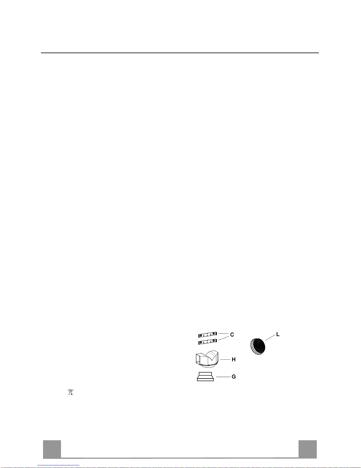
COMPONENTS
- 2 No Wall Brackets C
- 1 No 150-120mm Ducting Spigot G
- 1 No Air Outlet Connection H
- 2 No Charcoal Filters L (Optional)
The symbol on the pro duct or on its pack agin g indi cates t hat t his pro duct m ay n ot be tr eated as hous ehold wast e. Ins tead i t shal l
be handed ov er to the applicable c ollectio n point for the recyc ling of elec trical an d electroni c equipm ent. By ensur ing this product is
disposed of correctly, you will help prevent potential negative consequences for the environment and human health, which could otherwise be caus ed by in appr opr iat e wast e han dli ng of this produc t. F or mor e detai led infor mati o n about recyc li ng of this produc t , ple ase
contact your local city office, your household waste disposal service or the shop where you purchased the product.
Page 7

EN
7
7
INSTALLATION
The cooker hood must be installed centrally over a cooking appliance. The minimum distance
between the cooking surface and the metal grease filters on the underside of the hood must be
at least 650mm.
To install the hood proceed as follows:
1) Drill six 8mm diameter holes at X1-X2-J and insert the plastic rawl plugs supplied as illus-
trated in fig. 2 ensuring the brackets are fitted as shown in the blow up.
2) Secure th e two b rac kets C to the wall inserting two of the screws supplied through the two
holes on line X1-X2 as illustrated in fig. 2.
3) Slide the canopy down the wall to locate the key hole over the washer then secure the can-
opy to the wall by inserting two of the screws supplied through the two outer holes in the
rim of the canopy J1 and J2 as illustrated in fig. 3.
4) EXTRACTION OR RECIRCULATION INSTALLATION:
• EXTRACTION (DUCTED)
When installing the ducted version, connect the hood to the chimney using either a flexible or
rigid pipe ø 150 or 120 mm, the choice of which is left to the installer.
• To install a ø 120 mm air exhaust connection, insert the reducer flange 9 on the hood body
outlet.
• Fix the pipe in position using sufficient pipe clamps (not supplied).
• Remove an y activated charcoal filters.
• RECIRCULATION (FILTERED)
• When the hood is fitted in the recirculation mode the Air Outlet Connection H should be
fitted as illustrated in fig. 6.
• Fit the (optional) charcoal filters by repeating the following operation on each side of the
motor housing. Place the two key hole slots in the filter L and turn the filter clockwise to
lock the filter in position as illustrated in fig. 7.
WARNING: It is a possible fire hazard if the metal grease filters are n ot cleaned and the
charcoal filters replaced regularly.
Fitting The Chimney
5) FITTING TH E CHIMNE Y UPPER
To fit the upper chimney A, place th e top edge of th e chimne y over t he bracket C as illus-
trated in fig. 8 and secure the chimney using two of the 2.9mm self tapping screws provided.
The distance H in the height between the fixing holes X1 and X2 is determined by the
height of the upper chimney A.
6) F ITTI N G TH E CH IM N E Y LO W ER
To fit the lower chimney B, apply slight force to the t wo rear edges to increase the width
of the appertur e, then sleeve the chimney B over the chimney A as illustrated in fig. 9.
Page 8

EN
8
8
T2
T1
L
T3
USE - MAINTENANCE
USE
Control panel
BUTTON LED FUNCTIONS
T1 Speed On Turns the Motor on at Speed one.
Turns the Motor off.
T2 Speed On Turns the Motor on at Speed two.
T3 Speed Fixed When pressed briefly, t urns the Moto r on at Speed three.
Flashing Pressed for 2 Seconds.
Activates Speed four with a timer set to 10 minutes, after which it
returns to the speed that was set previously. Suitable to deal with
maximum levels of cooking fumes.
L Light Turns the Lighting System on and off.
Warning: Button T1 turns the motor off, after first passing to speed one.
MAINTENANCE
N.B. Before any maintenance, repairs or when changing the lights, always disconnect the appliance from the
power suppl y.
1. Lighting
This is provided by two 40 W lamps. To change these, proceed as follows (fig. 10):
Remove one of the pins at the sides of the light fixture. Slide the glass towards the side without the pin, until
the opposit e side is freed, then pull gently down wards. Change the la mps and re assemble the glass b y proceeding in reverse order.
2. Filters
At more or less frequent intervals, according to how much the hood is used, and in any case at least once
every 2 months, the metal filters sh ould be dismantled and washed in hot, soapy water, or directly in the
dishw asher, then dried and rep laced (the a ctivated cha rcoal filt ers must nev er be washed, an d must be replaced every 2 months).
3. Cleaning
To clean the exterior of the hood use a cloth damped with alcohol or other suitable commercially available
product s. Do not use abra s iv e s ub stances.
IMPORTANT: Use of an open flame may damage the filters, so it is not recommended that the gas burners
be left turned on without a pan over them. The hood and filters must be cleaned and replaced according to
the instructions provided in order to avoid the risk of fire.
WARNING: The manufacturer will not be considered liable for any damage caused by failure to carry out
maintenance on the metal grease filter (washing every two months), replacement of the activated charcoal filter and failur e to comply with the instructions for fitting and electrical connection provided above
.
Page 9

FR
9
9
ATTENTION - COMPOSANTS
ATTENTION
Cet appa reil a été c onçu pou r être emplo yé en versi on ASPIRANTE (évacu ation de l'air vers l'extérieu r)
ou en version RECYCLAGE (air conduite vers l'intérieur).
- La distance minimum entre le plan de cuisson et la partie inférieure de la hotte doit être au moins
de 650mm.
- Il faut prévoir une aération convenable de la pièce lorsque la hotte et les appareils alimentés avec
énergie différente de celle éléctrique sont utilisés en même temps; la pression négative de la pièce
ne doit pas dépasser 4Pa (4x10
-5
bar).
- L'a ir recueillie ne doit pas être dirigée dans un conduit utilisé pour la décharge des fumées des
appareils alimentés avec énergie différente de celle éléctrique.
- Respecter les prescriptions des autorités compétentes relatives à la décharge de l'air à evacuer.
- Eviter la présence de flammes libres dans l'espace au dessous de la hotte.
- La hotte a été construite avec isolement en classe II, donc il n'y a pas besoin de la relier à la terre.
- Avant d'effectuer toutes les opérations d'entretien, débrancher l'appareil de l'alimentation éléc-
trique.
- Cet a ppareil ne doit pas être utilisé par des personnes (y compris les enfants) ayant des capaci tés
psychiques, sensorielles ou mentales rédui tes, ni par des personnes n’ayant pas l’expérience et la
connaissance de ce type d’appareils, à moins d' être sous le contrôle et la formation de personnes
responsables de leur sécurité.
- Les enfants doivent être surveillés pour s'assurer qu'ils ne jouent pas avec l'appareil.
BRANCHEMENT DU CÂBLE ÉLECTRIQUE AU RÉSEAU
Avant l’ins tallation, véri fier que la tension du résea u indiquée su r la plaquette se t rouvant à l’in térieur de
l’appareil correspond à la tension électrique de votre habitation. Si la hotte n’est pas munie de fiche électrique, monter une fiche à norme sur le câble d’alimentation qui soit adaptée à la tension indiquée sur la
plaquet te des caractér istiques. En c as de branchem ent électriqu e direct sur le r éseau, il faud ra placer un
interrupteur omnipolaire entre l’appareil et le réseau ayant une ouverture minimum entre les contacts de 3
mm, et adap té à la tension et répondant aux normes en vigueur.
COMPOSANTS
- 2 brides C
- 1 bride de réduction G
- 1 raccord filtrant H
- 2 filtres charbon actif L (optionnel)
Le symbole
sur le prod uit ou so n embal lage i ndi que qu e ce pro duit ne peut être trai té comm e déc het m énager . Il doit plut ôt être
remis au point de ramassage concerné, se chargeant du recyclage du matériel électrique et électronique. En vous assurant que ce
produit est él imi né correc temen t, vous favori sez l a préve ntion des conséq uenc es nég atives p our l’ envir onnem ent et la sa nté hum aine
qui, sinon, s er ai e nt l e r ésultat d’un trai t em ent inappropri é d es d éc h ets d e c e produit. Pour obtenir plus de détails sur le rec yclage de ce
produit, veuillez prendre contact avec le bureau municipal de votre région, votre service d’élimination des déchets ménagers ou le
magasin où vo us av ez acheté le produit.
Page 10

FR
110
INSTALLATION
La hotte doit être assemblée au cent re du plan de cu isson. La distance minimum entre le p lan
de cuisson et la surface in férieure de la hotte doit être de 650mm.
Pour l'assemblage de la hotte procéder de la manière suivante:
1)Faire n°6 trous (X1-X2-J) de 8mm respectant les chiffres indiqués à la fig. 1.
2) Pour les différents assemblages utiliser les vis et les vis tamponnées fournies..
3) Bloquer l'étrier C (fig. 2) à la paroi dans les trous X1-X2.
4) Fixer la hotte à la paroi dans les trous J1 et J2 (fig. 3) .
5) Assemblage ASPIRANTE ou FILTRANT.
• ASPIRANTE
En cas d’installati on en versi on aspiran te, branch er la hotte à la tuyauterie de sortie via un tube
rigide ou flexible de ø 150 ou 120 mm, au choix de l’i nstallateur.
• En cas de branchement avec un tube de ø120 mm, insérer le flasque de réduction 9 sur la
sortie du corps de la hotte.
• Fixer le tube par des colliers appropriés. Le matériau nécessaire n’est pas fourni.
• Retirer les éventuels filtres anti-odeur au charbon actif.
• FILTRANT (OPTION)
- Insérer le Raccord Sortie Air H (fig. 6).
- Assembler les filtres charbon actif L (fig. 7) en les centrant dans le support moteur M et
les bloquer en tournant dans sens horaire (environ 10°) jusqu'à l'arret. Pour les opérations
de démontage faire les opérations inverses.
6) Fixer la che minée supérieure A (fig. 8) à l'étrier C (fig. 2/fig. 8) utilisant 4 vis autotarau-
deuses de Ø 2,9mm en dotation. La distance entre les alésages de fixation X1 et X2 est déterminée par la hauteur de la cheminée sup éri eure H.
7) Appliquer fron talement la cheminée inférieure B (fig. 9) en élargissant légèrement les deu x
parties latérales et l'insérer ensuite dans la hotte (fig. 9).
Page 11

FR
111
T2
T1
L
T3
UTILISATION - ENTRETIEN
UTILISATION
Panneau de commande
TOUCHE VOYANT FONCTIONS
T1 Vitesse Allumé Démarre le moteur en première vitesse.
Coupe le moteur.
T2 Vitesse Allumé Démarre le moteur en deuxième vitesse.
T3 Vitesse Fixe Appuyée brièvement, démarre le moteur en troisième vitesse.
Clignotant Appuyée pendant 2 secondes.
Démarre la quatrième vitesse avec une temporisation de 10 minutes,
après lesquelles le moteur retourne à la vitesse précédemment programmée. Fonction indiquée pour faire face aux pointes d’émission de fumées
de cuisson.
L Lumière Branche et débranche l’écla irage.
Attention : La touche T1 coupe le moteur en pass ant toujours par la première vitesse.
ENTRETIEN
N.B. Avant toute intervention d’entretien, réparation et remplacement des ampoules, débrancher l’appareil du
réseau électrique.
1. Eclairage
Il comprend deux ampoules de 40 W. Pour remplacer une ampoule, procéder de la manière suivante (fig.
10) :
En lever un d es gouj ons sur les c ôtés du pla fonnier. Faire cou lisser le verr e vers le cô té s ans goujon ju squ’à
ce que la pointe opposée soit libérée, puis tirer légèrement vers le bas . R emplacer les ampoules et remonter le
verre en suivant l’ordre inverse.
2. Filtres
A des intervalles plus ou moins fréquents, selon l’utilisation de la hotte, mais en tout cas une fois tous les 2
mois, il fau t démonter e t laver le s filtr es métalliqu es avec de l’eau ch aude et du s avon, ou le s laver di rectement dans un lave-vai ss elle , et pui s les remont e r quand ils sont secs (i l ne faut en au cun cas la ver les filt res à
charbon actif mai s les remplacer tous les 2 mois).
3. Nettoyage
Pou r le nett oyage externe de la hotte, utiliser un chi ffon humide ave c de l’alcool ou d es produits appropriés
disponibles da ns le commerce. Eviter d’utiliser des produits abrasifs.
IMPORTANT : L’u t ilis ati on de flamm es lib res p eut end omma ger le s filt res, il e st donc d écons eillé d e lais ser un
brûleur à gaz allumé sans casserole. Il est obligatoire d’effectuer les opérations de nettoyage de la hotte ou
des filtres, et de les remplacer périodiquement selon nos instructions afin d’éviter des risques d’incendie.
ATTENTION : Le fabricant ne peut en aucun cas être tenu responsable des dommages résultant du manque
d’entretien du filtre à graisse (lavage tous les deux mois), du non-remplacement du filtre à charbon et du
non-respect des instructio ns de montag e et de branc heme n t électr iq ue décri te s ci-de ssu s.
Page 12

DE
112
HINWEIS - KOMPONENTEN
HINWEISE
Dieses Gerät ist sowohl als ABLUFTHAUBE (Abführung der Luft nach außen), als auch als
UMLUFTHAUBE (Filtrierung der Dünste im Innern) verwendbar.
- Der Mindestabstand zwischen Kochfeld und Unterseite der Haube soll 650 mm betragen.
- Wenn die Luft nach Außen abgeführt wird (Abluftbetrieb), muss die Haube nach den folgenden An-
weisungen installiert werden.
- Bei gleichzeitigem Betrieb der Dunstabzugshaube im Abluftbetrieb und Feuerstätten darf im Auf-
stellraum der Feuerstätte der Unterdruck nicht größer als 4 Pa (4x10
-5
bar) sein.
- Das Abluftro hr der Haube darf keinesfall s an d en Rau chabzug von Feuerstät ten ang eschlo ssen wer-
den.
- Die Abluftvorschriften der zuständigen Behörden beachten.
- Niemals eine Flamme unter der Dunsthaube unbedeckt lassen.
- Das Gerät entspricht der Schutz klasse II und muss daher nicht geerdet werden.
- Vor Wartungsarbeiten muss das G erät spannungslos gemacht werden.
- Dieses Gerät darf nicht von Personen, auch Kindern, mit vermin derten psychischen, sen sorischen
und geistigern Fähi gkeiten, o der von Perso nen ohne E rfahrun g un d Ken ntni sse benu tzt werd en, sofern sie nicht von für ihre Sicherheit verantwortlichen Personen beaufsichtigt und beim Gebrauch
des Geräts angeleitet werden.
- Kinder dürfen sich nicht unbeaufsichtigt in der Nähe des Geräts aufhalten und auf keinen Fall mit
dem Gerät spielen.
ANSCHLUSS DES STROMKABELS AN DAS NETZ
Vor der Installation muss kontrolliert werden, ob die am Typenschild im Geräteinnern angegebene Netzspannung der Spannung Ihres Haushalts entspricht. Falls das Gerät ohne Stecker ist,
muss das Kabel mit einem genormten, für die am Typenschild angegebene Last ausreichenden
Stecker versehen werden; bei direktem Anschluss an das Netz muss ein korrekt dimensionierter allpoliger Schalter mit einer Mindestkontaktöffnung von 3 mm zwischengeschaltet werden,
der den einschlägigen Vorschriften entspricht.
KOMPONENTEN
- 2 Wandhalterungen C
- 1 Reduzierflansch G
- 1 Filterstutzen H (Option)
- 2 Aktivkohlefilter L (Option)
Das Symbol auf dem Produkt oder sein er V erp ac k u ng weist darauf hi n, dass dieses Produkt nicht al s n or m al er Haushaltsa bf al l z u
behandeln ist, sondern an einem Sammelpunkt für das Recycling von elektrischen und elektronischen Geräten abgegeben werden
muss. Durc h Ihren Beitrag zum korrekte n Entsorgen dies es P rodukts schützen Sie die Umwelt und di e G es u ndheit Ihrer Mi tm enschen.
Umwelt und Gesundheit werden durch falsches Entsorgen gefährdet. Weitere Informationen über das Recycling dieses Produkts
erhalten Sie von Ihrem Rathaus, Ihrer Müllabfuhr oder dem Geschäft, in dem Sie das Produkt gekauft haben.
Page 13

DE
113
MONTAGE
Die Haube muss mittig über dem Kochfeld installiert werden. Der Mindestabstand zwischen
Kochfeld und Unterseite der Haube soll 650 mm betragen.
Für die Installation wie folgt vorgehen:
1) 6 Löcher (X1-X2-J) mit 8 mm Durchmesser nach den Maßangaben der Abb.1 ausführen.
2) Die für die jeweilige Montage mitgelieferten Schrauben und Dübel verwenden.
3) Die Wandhalterung e n C (Abb. 2) mittels der Bohrungen X1-X2 an der Wand befestigen.
4) Die Haube mittels der externen Bohrlöcher J1 und J2 (Abb. 3) an der Wand befestigen.
5) Montage als ABLUFTHAUBE oder U MLUFTHAUBE:
ABLUFTBETRIEB
Bei Abluftbetrieb kann die Haube vom Installateur wahlweise mittels Rohr oder Schlauch (ø
150 oder 120 mm) an den Auslass angeschlossen werden.
- Bei Verwendung eines Anschlussrohres ø 120 den Reduzierflansch 9 am Haubenausgang
anbringen.
- Das Rohr mit passenden Rohrschellen fixieren. Das hierzu erforderliche Material wird
nicht mitgeliefert.
- Eventuell vorhandene Aktivkohlefilter ausbauen.
UMLUFTBETRIEB (OPTION)
- Den Filterstutzen H einbauen (Abb. 6).
- Den Aktivkohlefilter L (Abb.7) einlegen und durch Drehen im Uhrzeigersinn (um zirka
10°) einrasten lassen . Zum Ausbauen in umgekehrter Reihenfolge vorgehen.
Montage der Kami ne:
6) Befestigen Sie das obere Kaminteil A (Abb. 8) mit den vier beiliegenden, selbstschneiden-
den Schrauben Ø 2,9 mm an den Halterungen C (Abb.2/Abb.8). Der Abstand zwischen
den Bohrlöchern X1 und X2 hängt von der Höhe des oberen Kaminteils H ab.
7) Um das untere Kaminteil B (Abb. 9) anzubringen die beiden Seitenteile leicht auseinan-
derbiegen und dann an der Haube einsetzen (Abb. 9).
Page 14

DE
114
T2
T1
L
T3
BEDIENUNG - WARTUNG
GEBRAUCH
Bedienfeld
TASTE LED FUNKTIONEN
T1 Betriebsgeschwindigkeit Eingeschaltet Schaltet den Motor bei der ersten Betriebsgeschwindigkeit ein.
Stellt den Motor ab.
T2 Betriebsgeschwindigkeit Eingeschaltet Schaltet den Motor bei der zweiten Betriebsgeschwindigkeit e in.
T3 Betriebsgeschwindigkeit Bleibend Schaltet den Motor bei der dritten Betriebsgeschwindigkeit ein.
Blinkend Bei 2 Sekunden langem Drücken: Aktiviert die auf 10
Minuten geregelte vierte Betriebsgeschwindigkeit, nach deren Ablauf
zu der zuvor eingestellten Geschwindigkeit zurückgekehrt wird. Für
die Beseitigung von sehr intensiven Kochdünsten geeignet.
L Licht Schaltet die Beleuchtung ein und aus.
Achtung: Mit der Taste T1 wird von der ersten Betriebsgeschwindigkeit aus der Motor abgestellt.
WARTUNG
Hinweis Vo r jeder Wartungs- oder Reinigun gsarbeit oder dem eventuellen Austauschen von
Lampen das Gerät vom Netz trennen.
1. Beleuchtung
Besteht aus zwei 40 W-Lampen. Zum Ersetzen wie fo lgt vorgehen (Abb. 10):
Einen der Zapfen an den Seiten der Lampenabdeckung entfernen. Das Glas zur Seite ohne Zapfen
gleiten lassen, bis die gegenüberliegende Seite frei liegt, dann leicht nach unten ziehen. Die Lampen
ersetzen und das Glas in umgekehrter Reihenfolge wieder montieren.
2. Filter
In mehr oder weniger häufigen Abständen, je nach Benutzung der Haube, aber wenigstens alle 2 Monate, sind die Metallfilter auszubauen und mit heißer Seifenlauge oder direkt im Geschirrspüler zu
waschen und nach dem Trocknen wieder einzubauen (Aktivkohlefilter sind nicht waschbar und alle 2
Monate zu ersetzen).
3. Reinigung
Für die Außenreinigung der Haube ein feuchtes Tuch mit Alkohol oder geeigneten handelsüblichen
Reinigungs m itteln verwenden. Den Gebrauch von Scheuermitteln vermeiden.
WICHTIG: Der Gebrauch von offenem Feuer schadet den Filtern. Es ist daher nicht ratsam, Gasflammen ohne Topf brennen zu lassen. Die Reinigung der Haube bzw. der Filter sowie deren regelmäßiges Ersetzen nach Anweisung ist aus Brandschutzgr ünden unerlässl ich.
ACHTUNG: Der Hersteller haft et nicht für eventu elle Schäd en durch unterlassen e Wartung d es Fettfilters (Reinigung alle zwei Monate), Ersetzen des Kohlefilters und Nichtbeachten der oben beschriebenen Anleitungen für Montage und Elektroanschluss.
Page 15

UYARILAR - PARÇALARI
UYARILAR
Bu cihaz ASPİRATÖRLÜ (havayı dışarı tahliye eden) yada FİLTRELİ (içerideki havayı tekrar aktive
eden) model davlumbaz olarak tasarlanmıştır.
- Tezgâh (setüstü ocak) ile davlumbazın alt kısmı arasındaki mesafe en az 650 mm olmalıdır.
- Davl umbazda havanın dışarı tahliye edildiği (aspiratörlü kullanım şekli) söz konusu olduğunda
aşağıdaki talimatlara uyunuz.
- Davlumbaz ile elektrik enerjisinden farklı bir enerji ile çalışan cihazların ay nı anda çalışır du-
rumda oldukları mekânda iyi bir havala ndırma bulunmasına di kkat ediniz ; odanın nega tif basıncı (vakumu) 4 atmosfer basıncını aşmamalıdır (4x10
-5
bar).
- Mekânda toplanan hava, elektrik dışında bir enerji ile çalışan cihazlardan çıkan dumanları tahli-
ye eden kanala-bacaya sevk edilmemelidir.
- Ha va tahliyesi ile ilgili olarak yerel yetki mercilerinin yönetmeliklerine uyunuz.
- Davlumbazın altındaki alanda serbest alev bul unması na engel olunuz.
- Davlumbaz Sınıf’II ye da hil izolasyo na sahip olara k imal edil miştir ve bu nedenle toprak bağlan-
tısı gerekt irmez.
- Tüm bakım işlemlerinden önce cihazın elektrik bağlantısını kesiniz.
- Bu alet, güvenliklerinden sorumlu kişiler tarafından kontrol edilmedikleri veya eğitilmedikleri
sürece; fiziksel, duyumsal ve zihinsel kapasitesinde kısıtlama olan (çocuklar da hil) veya aleti kullanma tecrübesi ve bilgisi olmayan kişiler tarafından kullanılamaz.
- Bebeklerin, aletle oynamadıklarından emin olmak için kontrol edilmeli gerekir.
BESLEME KABLOSUNUN ŞEBEKEYE BAĞLANMASI
Yerleştirmeden önce, şebeke geriliminin cihazın içindeki etikette belirtilen gerilime uygun olduğunu kontrol ediniz. Davlumbazın bir kablosu olmaması durumunda, besleme kablosuna, özellikler etiketinde belirtilen yüke uyarlanmış bir fiş monte ediniz; şebek eye doğrudan elektrik bağlantısı yapılması halinde, cihaz
ile şebeke arasına, temaslar arasında minimum 3 mm'lik bir aralığı bulunan, yüke göre boyutlandırılmış ve
yürürl ükteki norma uy g un çok kutuplu bir şalter yerleştiriniz
PARÇALARI
- 2 adet tesbit braket i C
- 1 adet redüksiyon flan şı G
- 1 adet filtre rakoru H
- 2 adet aktif karbon filtresi L (isteğe bağlı)
Ürün veya paketi üz erindek i
sembolü, bu ürün ün normal bir evs el atık olarak g örülmemes i ve bu tip elektrik li veya elektr onik cihazların atıl dığı dönüşümlü t oplama n oktalarına t erkedil mesi gerekti ğine işaret eder. B u ürünü ger ektiği gibi elimine e tme kural larına
uyarsanız çevre ve insan sağlığı üzerindeki olum suz etkilerini b ertaraf etmeye katk ı sağlamış olursunuz. B u ürünün geri d önüşüm
koşulları hakkında daha ayrıntılı bilgi için hudutları içinde bulunduğunuz belediyenin ilgili diaresine, atık yoketme servisine veya ürünün
satıcısına da nışınız.
TR
1
6
15
Page 16

TR
116
MONTAJ
Davlumbaz setüstü ocağın tam merkezine monte edilmelidir. Setüstü ocak ile davlumbazın altı
arasındaki mesafe en az 650 mm olmalıdır.
Davlumbazın montajı için şu şekilde hareket ediniz:
1) Şekil 1’deki ölçülere uyarak 6 adet 8 mm çapında delik açınız (X1-X2-J).
2) Muhtelif parçaların montajlarında cihaz donanımındaki vidaları ve dübelleri kullanınız.
3) Braketleri C (şekil 2) duvardaki deliklere X1-X2 tesbit ediniz.
4) Davlumbazı duvardaki dış deliklere J1 ve J2 tesbit ediniz (şekil 3).
5) ASPİRATÖRLÜ yada FİLTRELİ modelin montajı:
• ASPIRATÖRLÜ
Aspiratörlü model montajında Davlumbazı çıkış borusuna seçimi montöre kalmış sert ya da
esnek 150 veya 120 mm çapında bir boru ile bağlayınız.
• 120 mm çapında boru ile bağlamak istiyorsanız Redüksiyon Flanşını 9 Davlu mbaz Gövde-
si Çıkışına takınız.
• Boruyu uygun kelepçelerle tesbit ediniz. Bu malzeme donanımda verilmemiştir.
• Varsa Aktif Karbonlu Koku Filtrelerini çıkarınız.
• FİLTRELİ (OPSİYONEL MODEL)
- Filtre rakorunu H takınız (şekil 6).
- Aktif karbonlu filtreleri L (şekil 7) saat yönünde (yaklaşık 10° derece) döndürüp klik sesi
duyunca takıldıklarını anlayınız. Sökerken bu işlemleri tersine yapınız.
Baca Montajı
6) Üst bacayı A (şekil 8) braketlere C (şekil 2 / şekil 8) donanımdaki 4 adet 2,9 mm.lik vidayı
kullanarak sabitleyiniz. Tesbit vidaları arasındaki X1 - X2 mesafesi üst bacan ın boyuna H
göre belirlenir.
7) Ön cepheden , yan taraflarını hafifçe açı p davlumbaza geçirmek sureti yle alt bacayı B (şe-
kil 9) monte ediniz (şekil 9).
Page 17

TR
117
T2
T1
L
T3
KULLANIM - BAKIMI VE TEMİZLENMESİ
KULLANIM
Kumanda Tablosu
TUŞ LED FONKSİYON
T1 Hız Açık Birinci hızda motoru çalıştırır.
Motoru durduruyor.
T2 Hız Açık İkinci hızda motoru çalıştırır.
T3 Hız Sabit Hafifçe basılınca, üçüncü hızda motoru çalıştırır.
Flaşör 2 saniye süreyle basılınca:
10 dakikaya ayarlanmış dördüncü hızı etkin duruma getirir. Bu süre-
nin sonunda, ayarlanmış olan bir önceki hıza geri döner. Pişirme anındaki dumanın fazla yayılmasını engellemeye uygundur.
L Işık Işık tesisatını açıp kapatır.
Dikkat: T1 tuşu daima ilk hızdan geçerek moto ru durdurur.
BAKIM
NOT. Herha ngi bir b akım, on arım müdah alesi ve olası lamba değiştirilmesinden önce, aygıtı elektrik
akımından ayırınız.
1. Aydınlatma
40 W’lık iki lambadan oluşmuştur. Her değiştirmeyi aşağıda belirtilen şekilde (Res i m 1 0 ) ger çek l eşti-
riniz:
Tavan lamb asındaki iki pimd en birini sökünüz. Camı, pim olma yan tarafa doğru, k arşıt uç serbest
kalana kadar kaydırınız ve sonra yavaşça aşağıya doğru çe ki niz .
Lambaları değiştirin ve camı dizi işlemi tersten uygula yarak yerleştiriniz.
2. Filtreler
Daha çok veya daha az sıklıktaki aralıklarla, davlumbazın kullanımı doğrultusunda, her halükarda her
2 ayda bir kez, metal filtrelerin demonte edilmeleri ve sabunlu suyla yıkanmaları veya doğrudan bulaşık makinesinde yıkanmaları ve tekrar monte edilmeleri gerekmektedir (aktif karbon filtrelerin kesinlikte yıkanmamaları, her 2 ayda bir değiştirmeleri gerekmektedir.)
3. Temizlik
Davlumbazın dış temizliği için, alkolle n emlendiri lmiş bir bez veya piyasada bulunan uygun ürünler
kullanınız. Aşındırıcı madde kullanmaktan kaçınınız.
ÖNEMLİ: Açıkta alev filtrelere zarar verir, bu nedenle tencere olmaksızın açık bırakılan bir gazlı
ateşleyicinin (ocak) açık bırakılması tavsiye edilmez. Yangın tehlikesini engellemek için davlumbazın veya filtrelerin temizli k i şlemlerini gerçekleştirmek, ayrıca talimatlarımız doğrultusunda periyodik
değiştirilmelerini yapmak zorunludur.
DİKKAT: Üretici firma, yağlanmaya karşı filtrelerin bakım (her iki ayda yıkama) eksikliğinden, kar-
bon filtrelerin değiştirilmemesinden ve yukarıda tanımlanan montaj ve elektrik bağlantısı talimatları-
na uyulmamasından kaynaklanan zararlardan sorumlu değildir.
Page 18

S30_02_n
X
X1
J
1
2
C
X2
H
S30_03_n
J
1
2
750 min
1
140 max
S30_01_n
600
700
900
290
590 min
15
H
J
X1
A
B
275
180
= =
X2
180
180
= =
= =
J
C
1
2
3
4 5
G
Page 19

6
7
8
9
10
B
H
H
L
L
M
Page 20

436004860_ver1
Franke S.p.a.
Via Pignolini,2
37019 Peschiera del Garda (VR)
www.franke.it
 Loading...