

Page 1

REGATTA RB
Range Hood
Hotte
Installation Instructions
Use and Care Guide
Instructions d’installation
Mode d’emploi et d’entretien
FDL 367 W XS RB
FDL 487 W XS RB
Page 2

EN
2
2
INDEX
WARNINGS AND REQUIREMENTS.....................................................................................................................................3
RECOMMENDATIONS AND SUGGESTIONS......................................................................................................................6
DIMENSIONS and MAIN PARTS...........................................................................................................................................7
INSTALLATION ......................................................................................................................................................................8
USE.......................................................................................................................................................................................11
CARE....................................................................................................................................................................................12
Page 3

EN
3
3
READ AND SAVE THESE INSTRUCTIONS
The Installer must leave these instructions with the homeowner.
The homeowner must keep these in structions for futu re reference an d for local electri cal inspectors’ use.
READ THESE INSTRUCTIONS BEFORE YOU START INSTALLING THIS RANGEHOOD
WARNING: - TO REDUCE THE RISK OF A RANGE TOP GREASE FIRE:
a) Never leave surface units unattended at high settings. Boilovers cause smoking and greasy
spillovers that may ignite. Heat oils slowly on low or medium setting.
b) Always turn hood ON when cooking at high heat or when flambéing food (i.e. Crepes Suzette,
Cherries Jubilee, Peppercorn Beef Flambé.
c) Clean ventilating fans frequently. Grease should not be allowed to accumulate on fan or filter.
d) Use proper pan size. Always use cookware app r opriate for the size of the su rface element.
WARNING: - TO REDUCE THE RISK OF INJURY T O PERSONS IN T HE EVE NT OF A RANGE
TOP GREASE FIRE, OBSERVE THE FOLLOWING:
a) SMOTHER FLAMES with a close-fitting lid, cookie sheet, or metal tray, then turn off the
burner. BE CAREFUL TO PREVENT BURNS. If the flames do not go out immediately
EVACUATE AND CALL THE FIRE DEPARTMENT.
b) NEVER PICK UP A FLAMING PAN - You may be burned.
c) DO NOT USE WATER, including wet dishcloths or towels - a violent steam explosion will
result.
d) Use an extinguisher ONLY if:
1. You know you have a Class ABC extinguisher, and you already know how to operate it.
2. The fire is small and contained in the area where it start ed.
3. The fire department is being called.
4. You can fight t he fire with your back to an exit
.
(*) Based on “ Kitchen Firesafety Tips” published by NFPA.
ALL WALL AND FLOOR OPENINGS WHERE THE RANGE HOOD IS INSTALLED MUST BE
SEALED.
This rangehood requires at least 24" of clearance between the bottom of the rangehood and the
cooking surface or countertop. This minimum clearance may be higher depending on local building code. Consult the cooktop or range installation instructions given by the manufacturer before
making any cutouts.
VENTING REQUIREMENTS
CAUTION - To reduce risk of fire and to properly exhaust air, be sure to duct air outside – Do not vent ex-
haust air into spaces within walls or ceilings or into attics, crawl spaces, or garages".
Determine which venting method is best for your application. Ductwork can extend either
through the wall or the roof. The length of the ductwork and the number of elbows should be
kept to a minimum to provide efficient performance. The size of the ductwork should be uniform. Do not install two elbows together. Use duct tape to seal all joints in the ductwork system.
Use caulking to seal exterior wall or floor opening around the cap.
Flexible ductwork is not recommended. Flexible ductwork creates back pressure and air turbulence that greatly reduces performance.
Make sure t here is proper clearance within the wall or floor for exhaust duct b efore making cutout s.
Do not cut a joist or stud unless absolutely necessary. If a joist or stud must be cut, then a supporting
frame must be constructed.
WARNING - To Reduce The Risk Of Fire, Use Only Metal Ductwork.
Page 4

EN
4
4
W A R N I N G
• Venting system MUST terminate outside the home.
• DO NOT terminate the ductwork in an attic or other enclosed space.
• DO NOT use 4" laundry-type wall caps.
• Flexible-type ductwork is NOT recommended.
• DO NOT obstruct the flow of combustion and ventilation air.
• Failure to follow venting requirements may result in a fire.
ELECTRICAL REQUIREMENTS
A 120 volt, 60 Hz AC-only electrical supply is required on a separate 15 amp fused circuit. A
timedelay fuse or circui t breaker is recommended . The fuse must be sized per local codes in accordance with th e electrical rating o f thi s un it as sp ecified o n th e serial/ ratin g p late l ocat ed insi de
the unit near the field wiring compartment. THIS UNIT MUST BE CONNECTED WITH COPPER WIRE ONLY. Wire sizes must conform to the requirements of the National Electrical
Code, ANSI/NFPA 70 - latest edition, and all local codes and ordinances. Wire size and connections must conform with the rating of the appliance. Copies of the standard listed above may be
obtained from:
National Fire Pr otection Association
Batterymarch Park
Quincy, Mass achusetts 02269
This appliance sh ould be connected directl y to the fused disconnect (or ci rcuit breaker) through
flexible, armored or nonmetallic sheathed copper cable. Allow some slack in the cable so the appliance can be moved if servicing is ever necessary. A UL Listed, 1/2" condui t connector must
be provided at each end of the power supply cable (at the appliance and at the junction box).
When making the elect rical connection, cut a 1 1/4" hole in the wall. A hole cu t through wood
must be sanded until smooth. A hole through metal must have a grommet.
WARNING - TO REDUCE THE RISK OF FIRE OR ELECTRIC SHOCK,
do not use this fan with
any solid - state sp eed control device.
WARNING - TO REDUCE THE RISK OF FIRE, ELECTRICAL SHOCK, OR INJURY TO
PERSONS, OBSERVE THE FOLLOWING:
a) Use this unit only in the manner intended by the manufacturer. If you have any questions, con-
tact the manufacturer.
b) Before servicing or cleaning unit, switch power off at service panel and lock the service dis-
connecting means to prevent power from being switched on accidentally. When the service
disconnecting means cannot be locked, securely fasten a prominent warning device, such as a
tag, to the service panel.
CAUTION:
For General Ventilating Use Only. Do Not Use To Exhaust Hazardous or Explosive Materials
and Vapors.
CAUTION:To reduce the Ris k Of Fire And Electric Shock, Install This Rangehood Only
With Remote Blower Models Rated Maximum 1,8 A.
Page 5

EN
5
5
WARNING - TO REDUCE THE RISK OF FIRE, ELECTRICAL SHOCK, OR INJURY TO
PERSONS, OBSERVE THE FOLLOWING:
Installation Work And Electrical W iring Must Be Done By Qualified Person(s) In Accordanc e
With All Applicable Codes And Standards, Including Fire-Rated Construction.
Sufficient air is needed for proper combustion and exhaust ing of gases through the flue
(chimney) of fuel burning equipment to prevent backdrafting. Follow the heating equipment
manufacturer’s guideline and safety st andards such as t hose published by the National Fire
Protection Association ( N FPA), and the American Society for Heating, Refrigeration and Air
Conditioning Engineers (ASHRAE), and the local code authorit ies.
When cutting or drilli ng into wall or ceiling, do not damage electrical wiring and other hidden
utilities.
Ducted fans mus t always be vented to the outdoors.
W A R N I N G
• Electrical ground is required on this rangehood.
• If cold water pipe is interrupted by plastic, nonmetallic gaskets or other materials, DO
NOT use for grounding.
• DO NOT ground to a gas pipe.
• DO NOT have a fuse in the neutral or grounding circuit. A fuse in the neutral or grounding circuit could result in electrical shock
• Check with a qualified el ectrici an i f you are in dou bt as to whether t he ran gehoo d is prop erly grounded.
• Failure to follow electrical requirements may result in a fire.
Page 6
EN
6
6
RECOMMENDATIONS AND SUGGESTIONS
The Instruc tio ns for Use a pply t o s everal versi ons of this a ppli ance. Ac co rd-
ingly, you may find descriptions of in dividual features th at do not apply to
your specific appliance.
INSTALLATION
• The manufacturer will no t be held liable for any damages re sulting from in correct or improper installation.
• Check that the main voltage corresponds to that indicated on the rating plate
fixed to the inside of the hood.
• The electric al supply must be properl y and sufficiently grounded.
Connect the extractor to the exhaust flue through a pipe of minimum diameter
6”. The route of the flue must be as short as possible.
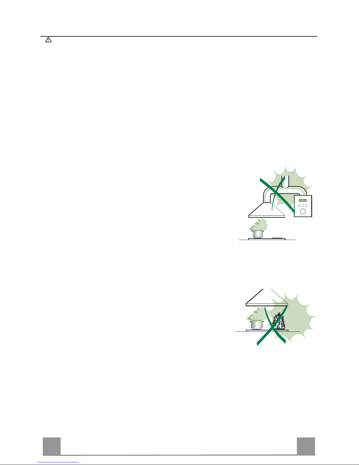
• Do not connect the extractor hood to exhaust ducts carrying combustion fumes
(boilers, fireplaces, etc.).
• If the extractor is used in conjunction with non-electrical appliances (e.g. gas
burning appliances), a sufficient degree of aeration must be guaranteed in the
room in order to prevent the backflow of exhaust gas. The kitchen must have
an opening communicating directly with the open air in order to guarantee the
entry of clean air.
USE
• The range hood has been designed exclusively for domestic use to eliminate
kitchen o dors.
• Never use the hood for purp oses other t han for which it has ben designed.
• Never leave high naked flames under the hood when it is in oper ation.
• Adjust the flame intensity to direct it onto the bottom of the pan only, making
sure that it does not engulf the sides.
• Deep fat fryers must be continuously monitored during use: overheated oil can
burst into flames.
• The hood should not be used by children or persons not instructed in its correct use.
CARE
• Switch off or unplug the appliance from the main supply before carrying out
any maint enance work.
• Clean and/or re place the Fi lters after the specified time period.
• Clean the hood using a damp cloth and a neutral liquid detergent..
Page 7
EN
7
7
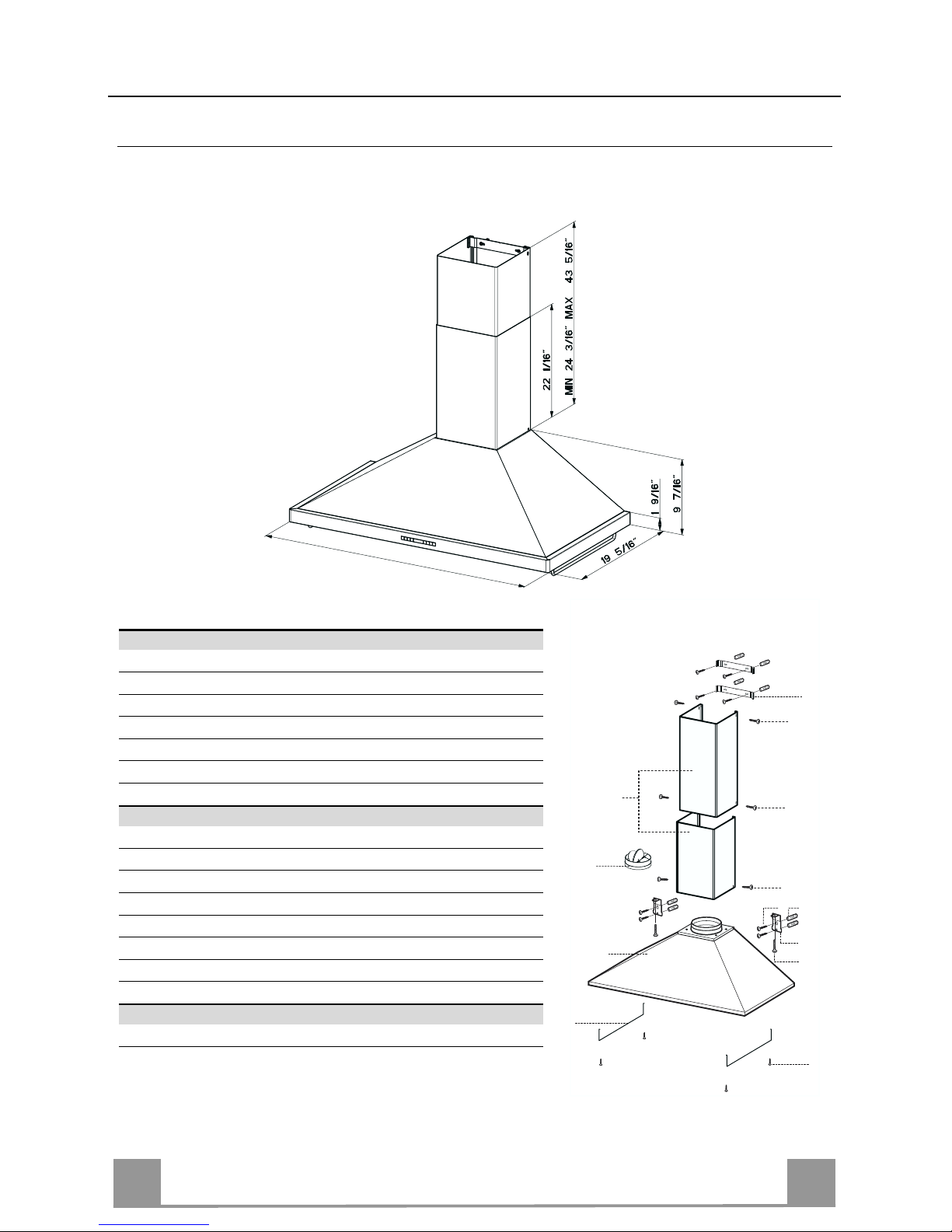
DIMENSIONS and MAIN PARTS
Dimensions
47" 1/6 - 36"
Components
Ref. Q.ty Product Components
1 1 Hood Body, complete wi th: Controls, Light, Filters
2 1 Telescopic Chimney comprising:
2.1 1 Upper Section
2.2 1 Lower Section
3 1 Hanging rails
10 1 Damper
15 1 Air Outlet C onnection
Ref. Q.ty Installation Compo ne nts
7.1 2 Hood Body Fixing Brac ket s
7.2.1 1 Upper Chimney Section Fixing Brackets
7.3 1 Air Outlet Connection Support
11 8 Wall Plugs ( if supplied)
12a 8 Screws 3/16” x 1” 3/4
12c 10 Screws 1/8” x 3/8”
12d 2 Screws 3/16” x 1”
12e 2 Screws 1/8” x 1/2“
Q.ty Documentation
1 Instruction Manual
7.2.1
1
3
12c
12c
12c
12c
2.1
2.2
2
10
7.1
12a 11
12d
Page 8
EN
8
8
INSTALLATION
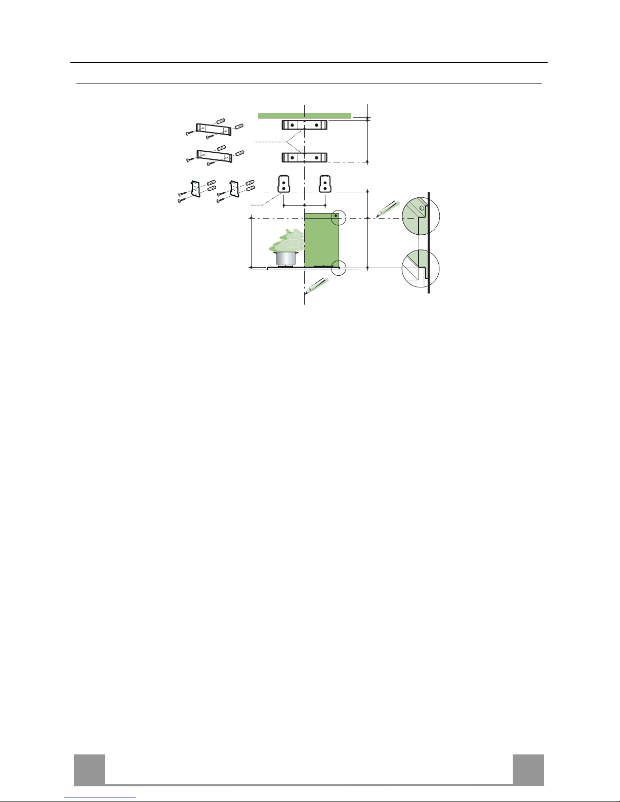
Wall drilling and bracket fixing
Wall marking:
• Draw a vertical line on the supporting wall up to the ceiling, or as high as practical, at the
center of the area in which the hood will be installed.
• Draw a horizontal line at 24” above the hob for installation without the back panel, or at
height H (height of the visible part of the panel) for installation with the back panel.
• Place bracket 7.2.1 on the wall as shown about 1/16” from the ceiling or upper limit, align-
ing the center (notch) with the vertical reference lin e.
• Mark the wall at the centers of the holes in the bracket.
• Place bracket 7.2.1 on the wall as shown at X” below the first bracket (X = height of the upper chimney section supplied), aligning the center (notch) with the vertical line.
• Mark the wall at the centers of the holes in the bracket.
• Place bracket 7.1 as shown 4” 5/16 from the vertical reference line and 7” 1/2 above the
horizontal reference line.
• Mark the centres of the holes i n the bracket.
• Repeat this operation on the other side.
REAR PANEL (OPTIONAL)
The Rear Panel must be fitted before fixing the hood body and, if it is to be fixed at both top
and bottom, must be fitted at the correct height prior to installing the bases. As this operation is
rather complex, it should be carried out either by the kitchen installer or a qualified person
who knows the final dimensions of the units.
For fixing at the top only, proceed as follows:
• Rest the back panel o n th e base, i nsertin g the lo wer plate bet ween th e upper su rface and t he
wall, centring it on the vertical reference line.
• Mark the centres of the two holes in the upper plate.
• Drill ø 5/16” holes at all the centre points marked.
• Insert the wall plugs 11 in the holes.
• Fix the brackets usin g th e 12a screws supplied.
• Fix the back panel (where present) using the 12a screws supplied.
H
X
7.2.1
7.1
24"
÷1/16"
7"1/2
4" 5/16
4" 5/16
Page 9
EN
9
9
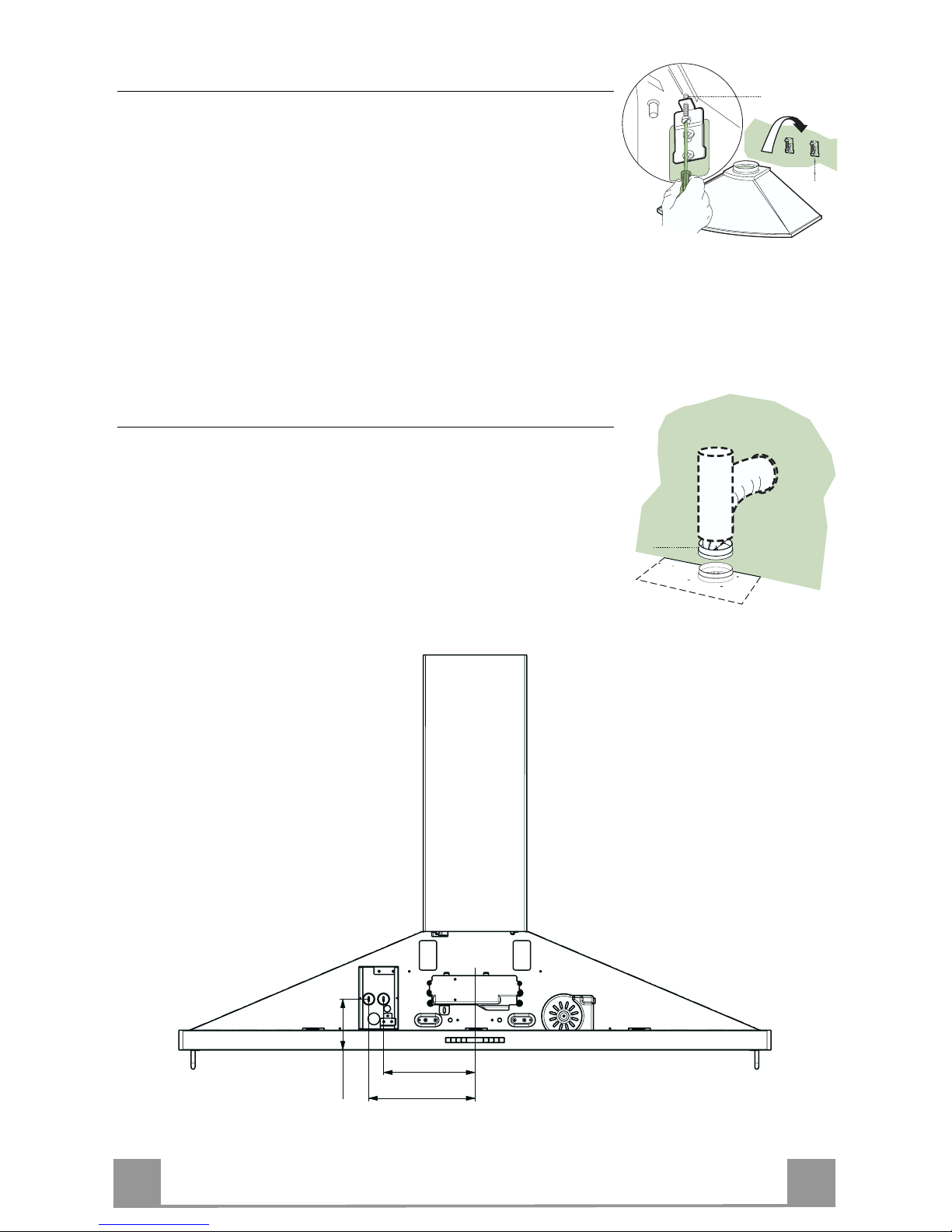
Mounting the hood body
• Screw the two screws 12d supplied onto the brackets 7.1.
• Hook the hood body onto the bracket 7.1, centring it around
the vertical line.
• Use the adjust ing screws 12d underneath the hood to level the
hood body.
Note: The Hood body should be secured to wall studs. If necessary, install a wood support behind the dry wall, flush mounted
between 2 studs. This will provide the necessary structure and
support for mounting.
12.d
7.1
Connections
DUCTED VERSION AIR EXHAUST SYSTEM
When installing the ducted version, connect the hood to the
chimney using a rigid 6” duct.
• Install the damper 10 ø 6”.
• Fix the duct in position using sufficient pipe clamps (not supplied).
10
8" 3/16
7"
3" 1/2
Page 10

EN
110
ELECTRICAL CONNECTION
Remove the wiring box cover by removing the two screw.
Insert the cable of the remote blower into the knockout hole
of the rangehood. Insert the power supply cable into the hole
of the rangehood. Connect the green ground wire from the
supply to the ground screw. Connect the green ground wire
from the remote blower to the other green gfround screw.
Exterior blower motor wiring:
• Connect the remote blower motor wire to the blue Rangehood wire with a twist-on connector.
• Connect the other remote blower motor wire to brown
Rangehood wire with a twist-on connector.
120-volt supply wiring:
• Connect 120-volt black supply wire to black Rangehood
wire with a twist-on connector.
• Connect 120-volt supply white wire with to white Rangehood wire with a twist-on connector.
Replace the wiring box co ver Tighten the screw securel y.
Reinstall the baffle filters. Reconnect the power.
green
ground
screw
green
ground
wires
white
wires
black wires
(from blower)
white wires
(from blower)
twist-on
connector
black
wires
exterior
blower
wiring
power
supply
cable
browm wires
(from Rangehood)
blue wires
(from Rangehood)
Rangehood
wiring
Chimney assembly
Upper exhaust Chimney
• Slightly widen the two sides of the upper flue and hook
them behind the brackets 7.2.1, making sure that they are
well seated.
• Secure the sides to the brackets using the 4 screws 12c
supplied.
Lower exhaust Chimney
• Slightly widen the two sides of the chimney and hook
them between the upper chimney and the wall, making
sure that they are well seated.
• Fix the lower part laterally to the hood body using the 2
screws 12c supplied.
12c
2.1
2.2
2
7.2.1
12c
Kitchen rail assembly
• Fix rails 3 to the bottom part of the Hood using the 12c
screws (2.9 x 9.5) supplied with the appliance.
12c
3
Page 11

EN
111
USE
A B C D E F G H
Control board
Key Function Display
A
Switches the blower motor on and off at the
latest selected speed
Indicates the selected speed.
B
Decreases the vent speed.
C
Increases the vent speed.
D
By pressing this key it is possible to activ
ate
the intensive speed from any previously selected sp eed. The inten sive speed can be a ctivated even when the mo tor is OFF. T his speed
has been timed at 10 minutes. After that time
the system activates automatically the latest
selected speed. This function is recommended
for cooking cond ition where vapors and odors
need to be eliminated immediately and q uickly.
HI appears. The spot down on the right side
flashes once a second.
E
By pressing this key it is possible to set up the
motor to a suction speed at 60 CFM lasting 10
minutes every hour. After this the motor
switches off automatically.
When the filter saturation is going on it is possible to reset the alarm by pressing this key for
about 3 sec onds. The indica tion is visible on ly
when the motor is off.
Indicates the 24-function. The spot down on
the right side flashes and the motor is on.
Once the process i s finished th e previous indication disa ppe ar s :
FF Indicates that the metal grease filters
saturation alarm has been triggered, and
the filt ers need to b e washed. The alarm
is triggered after 100 working hours.
EF Indicates that the charcoal filter satura-
tion alarm has been triggered, and the filter has to be replaced; the metal grease
filters must also be washed. The charcoal
filter is triggered after 200 working hours.
F
By pressing this key it is possible to set the
delayed shutdown of the appliance to 30 minutes. This function is suitable for a complete
elimination of the residual odors. It can be activated at any posi tion, and it is deacti vated by
pressing the key again or by switching off the
motor.
Indicates both the selected speed of the h ood
and the time left before the hood shutdown.
The spot down on the right side flashes alternately displaying the speed and shutdown time.
G
Turns light on and off .
H
Turns light on and off at reduced intensity.
Page 12

EN
112
CARE
REMOTE CONTROL (OPTIONAL)
This range hood can be controlled by a multi-function remote
control available through your local Franke Dealer.
Metal grease filters
Filters can be washed in the dishwasher. They need to be washed
when FF-sign appears on the display or in any case every 2
months, or even more frequently in case of particularly intensive
use of the hood.
Alarm reset
• Switch off the hood and the lights. If the 24h-function has been
activated this has to be deactivated.
• Press the E-key till the display is unlit.
Cleaning the filters
• Remove the filters one at a time holding them up with one
hand and pulling the handle downwards with the other hand at
the same time.
• Wash the filters, taking care not to bend them. Allow them to
dry before refitting.
• When refitting the filters, make sure that the handle is visible
on the outside.
Page 13

EN
113
Lighting
LIGHT REPLACEMENT
20 W halogen light.
• Remove the 2 screws fixing the Lighting support, and pull it
out of from the Hood.
• Extract the lamp from the Support.
• Replace with another of the same type, making sure that the
two pins are properly inserted in the lamp holder socket holes.
• Replace th e Support, fixing it in place with the two screws removed as above.
Page 14

14
FR
114
TABLE DES MATIÈRES
AVERTISSEMENT ET CONDITIONS N ÉCESSAIRES......................................................................................................14
CONSEILS ET SUGGESTIONS ..........................................................................................................................................17
DIMENSIONS et PRINCIPALES PIÈCES............................................................................................................................18
INSTALLATION ....................................................................................................................................................................19
UTILISATION........................................................................................................................................................................22
SOIN ET ENTRETIEN..........................................................................................................................................................23
Page 15

15
FR
115
LIRE ET CONSERVER CES INSTRUCTIONS
L’installateur doit laisser ces instr uctions au propr iétaire.
Le propriétaire doit conserver ces instructions en vue d’une utilisation subséquente et pour le bénéfice de
l’inspecteur en électricité.
LISEZ BIEN CETTE FICHE AVANT D’UTILISER LA HOTTE
AVERTISSEMENT – POUR MINIMISER LE RISQUE D’UN FEU DE GRAISSE SUR LA CUISINIERE :
a) Ne jamais laisser un élément de la surface fonctionner sans surveillance à la puissance de chauffage maximale; un renver-
sement/déborde ment de ma tière g raisse use po urrait pr ov oquer un ince ndie o u cau ser d e la fumée .
b) Utiliser toujours une puissance de chauffage moyenne ou basse pour faire chauffer de l'huile. Veiller à toujours faire
fonctionner l e v e ntil a te ur de l a ho tte lors d’une cuisson a v e c une puissance de chauffage élevée ou lors de la cuisson d’un
mets à flamber (i.e. Crêpes Suzette, Cherries Jubilee, Peppercorn Beef Flambé).
c) Nett oyer fréquemment les vent ilateurs d’extract ion. Veiller à ne pas laisser d e la graisse s’accumuler sur les surfaces du
ventilateur ou des filtres.
d) Utiliser toujours un uste nsil e de tail le appro priée.
AVERTISSEMENT – POUR RÉDUIRE LE RISQUE DE DOMMAGES CORPORELS APRÈS LE DÉCLENCHEMENT D’UN FEU DE G RAI SSE S U R LA CUISINIÈRE, A P PLIQUER LES RECOMMA N DATIONS
SUIVANTES :
a) ÉTOUFFEZ LE FEU AVEC UN COUVERCLE METALLIQUE ET FERMEZ LE BRULEUR. FAITES AT-
TENTION DE NE PAS VO US BRÛLER. SI LE FEU NE S’ETEINT PAS IMMEDIATEMENT, quittez les lieux et
appelez les po mpier s.
b) Ne touchez jamais une casserole en flammes – VOUS POURRIEZ SUBIR DES BLESSURES.
c) N’UTILISEZ JAMAIS DE L’EAU OU UN TORCHON MOUILLE POUR ETEINDRE LE FEU – CE QUI
POURRAIT CAUSER UNE EXPLOSION DE VAPEUR. vapeur brûlante.
d) Utiliser un extincteur S EUL EME NT si :
1. I l s’ag it d’un ex tincte ur de cl asse A BC, do nt on co nnaît l e fo nctionne ment.
2. I l s’ag it d’un pe tit f eu enco re l imité à l’endro it où il s’est dé cla ré.
3. Les pompiers ont été contactés.
4. I l est po ssible de ga rder l e do s orienté v ers une sortie penda nt l ’o pératio n de lutte contr e le f eu.
N’utilisez un extincte ur que s i:
1. Vous avez sous la main un modèle ABC et vous comment l’utiliser correctement.
2. Le feu est f aible e t peu répan du.
3. Les pompier s sont déjà pré venus.
4. Vous conserv ez une sortie derriè re v ous.
TOUTE OUVERTURE DANS LE MUR OU LE PLANCHER À PROXIMITÉ DE LA HOTTE DOIT ÊTRE
SCELLÉ
Gardez 24 po. de hauteur entre le bas de la hotte et la surface de cuisson. Consultez la fiche technique
avant de découper les armoires. INSTALLATION DANS UNE MAISON MOBILE.
EXIGENCES DE VENTILATION (ÉVACUATION)
ATTENTION – Afin de réduire le risque d’incendie et pour bien évacuer l’air, assurez-vous de faire échapp er l’air des
conduits à l’extérieur – Ne jamais évacuer l’air vers des espaces comportant des murs ou des plafonds ou dans le grenier, la
galerie ou le garage.
Déterminer l a métho de d’é vac uation de l’a ir la plus a ppropr iée po ur l’ applic ation. La sortie d’eva cuatio n : so it par l e mur ,
soit par le toit. U til isez une l ong ueur de tuy auterie minim ale , inclua nt le m oins de c ou des po ssibl e pour une pl us g rande ef f icacité. Le calibre de la tuyauterie doit être uniforme. N’installez jamais 2 coudes ensembles. Scellez bien tous les joints
avec un ruban adhésif métallique à l'intérieur et scellez bien le clapet extérieur en utilisant du calfeutrage.
L’utilisation d’un tuyau d’évacu ation flexible n ’est pas recommandée. Les tu yaux flex ibles créent une
contre-pression et de la turbulen ce, ce qui réduit la pu issance d'évacu ation.
Veillez à ce que l’espace pour le tuyau soit amplement suffisant, ainsi vous n’aurez pas à découper les supports de mur intérieur. On ne doit couper une solive ou un poteau de colombage que lorsque cela est absolument nécessaire. S’il est nécessaire
de couper une sol ive ou un po teau d u col ombag e, o n doit c onstruir e une struc ture de suppo rt ap pro priée.
AVERTISSEMENT – Afin de réduire le risque d’incendie, utilisez seulement des conduits en métal.
Page 16

16
FR
116
AVERTISSEMENT
• Le système d’évacuation DOIT se terminer à l’ extérieur.
• N’ÉVACUEZ PAS le condu i t dans un grenier ou dans tout autre espace fermé.
• N’UTILISEZ PAS un clapet de sécheuse à 4 pouces.
• ON DÉCONSEILLE l’emploi de conduit d’évacuation flexible.
• N’ENCOMBREZ PAS la circulation d’air.
• Le fait de ne pas respecter ces avertissements pourrait occasionner un incendie.
FICHE TECHNIQUE ÉLECTRIQUE
Le raccordement électrique doit se faire avec un circuit séparé de 15 ampères fusibles à 120 V, 60 Hz, courant alternatif. Nous recommandons un coupe-circuit. La taille du fusible doit se conformer aux codes municipaux suivant la spécification électrique sur la plaque intérieure. CET APPAREIL NE DOIT ÊTRE
CONNECTÉ QU’EN UTILISANT DES FILS EN CUIVRE. Le diamètre du fil devra aussi se conformer aux
règlements du code national élect rique,
ANSI/NFPA 70, ainsi qu’aux règlements locaux et les spécifications de cet appareil. On peut obtenir ces informations auprès de :
National Fire Protection Association
Batterymarch Park
Quincy, Massachusetts 02269
Raccordez cet appa reil directement au coupe-cir cuit( ou au disjoncteur) par l’intermédiaire de câble à
conducteurs de cuivre, à blindage métallique flexible ou à gaine non-métallique. Un serre-câble de ½ po.
(12,7 mm) (homologation UL ou CSA) doit être installé à chaque extrémité du câble d'alimentation (sur la
hotte et sur le boîtier de distribution).
Faites un trou de 1 ¼ po. dans le mur. S’il s’agit d'un mur en bois, sablez bien le trou. Tandis qu'un trou
dans le méta l demande un oeillet (passe-fil).
AVERTISSEMENT – POUR RÉDUIRE LE RISQUE D’INCENDIE OU DE CHOC ÉLECTRIQUE, ne
pas utiliser ce vent ilateur en conjonction avec un dis positif de réglage de vitesse à semi - conducteurs.
AVERTISSEMENT – POUR MINIMISER LES RISQUES D’INCENDIE, CHOC ÉLECTRIQUES OU
BLESSURES, OBSERVER CETTE RÈGLE :
a) Suivez strictement les recommandation s du fabricant ; en cas de nécessité veuillez le contacter.
b) Avant d’entreprendre un travail d’entretien ou de nettoyage, interrompre l’alimentation de la hotte au ni-
veau du tableau de disjoncteur, et verrouiller le tableau de disjoncteur pour empêcher tout rétablissement
accidentel de l’alimentation du circuit. Lorsqu’il n’est pas possible de verrouiller le tableau de disjoncteur
une étiquette d’avertissement proéminent interdisant le rétablissement de l’alimentation.
IMPORTANT : Pour une ventilation de type général seulement. Ne pas utiliser cet appareil pour
l’évacuation de matières ou vapeurs explosives.
IMPORTANT: Pour Minimiser Les Ri sques D’Incendie, Choc Électri ques, Installez La
Hotte Seulement Avec Venti lateur Extérieur Modèles Nomi nale Maximale de 1,8 A.
Page 17

17
FR
117
AVERTISSEMENT – POUR MINIMISER LES RISQUES D’INCENDIE, CHOC ÉLECTRIQUES OU
BLESSURES, OBSERVER CETTE RÈGLE :
L’inst allation et le raccordement électrique ne doivent être effect ués que par un technicien(s) qu alifié, selon
tous les codes municipaux.
Afin d’obtenir un rendement maximal en ce qui a trait à la combustion ainsi qu’à l’évacuation des
gaz par la conduite de cheminée et pour qu’il n’y ait pas de reflux des gaz de combustion, une
bonne aération est nécessaire pour tous les appareils à combustion. Suivez l es cons eils et mesures de sécurité du fournisseur tels que ceux publiés par la National Fire Protection Association
(NFPA) et l’American Society for Heating, Refrigeration and Air Conditi on Engineers (ASHRAE)
ainsi que les codes municipaux.
Lors d’opération de découpage et de perçage dans un mur ou un plafond, veiller à ne pas endommager les câblages électriques ou canalisations qui peuvent s’y trouver.
Un conduit de ventilation doit toujours se terminer à l'extérieur.
AVERTISSEMENT
• Une prise à la terre est nécessaire pour cette hotte.
• N’UTILISEZ PAS un tuyau à l’eau fro ide pour la mise à la terre s’il est connecté à du
plastique, un joint non métallique ou autre matériel.
• N’EFFECTUEZ PAS la mise à la terre sur la conduite de gaz.
• NE PAS INSTALLER un fusible dans le conducteur neutre ou le conducteur de liaison à
la terre.
• Vérifiez avec un électricien qualifié que la hotte est bien mise à la terre.
• Le fait de ne pas respecter ces avertissements pourrait occasionner un incendie.
Page 18

18
FR
118
CONSEILS ET SUGGESTIONS
Les instructions d’utilisation s’applique à plusieurs versions de ce type
d’appareil. En conséquence, il est possible que vous trouviez des descriptions
de caract éristiques ne s'appli quant pas à votre appareil.
INSTALLATION
• Le fabricant décline toute responsabilité en cas de dommage dû à une installation inadéquate ou non conforme aux règles de l’art.
• Vérifiez que la tension du secteur correspond à la valeur qui figure sur la plaquette apposée à l’intérieur de la hotte.
• L’alimentation électrique doit être adéquatement et suffisamment mise à la
terre.
Connectez la hotte à la sortie de l’air aspiré à l’aide d’une tuyauterie d’un dia-
mètre ou supérieur à 6 po. Le parcours de la tuyauterie doit être le plus court
possible.
• Évitez de connecter la hotte à des conduites d’évacuation de fumées issues
d’une combustion tel que une chaudière, un e cheminée, etc.
• Si vous utilisez des appareils qui ne fonctionnent pas à l’électricité dans la
pièce ou est installée la hotte (par exemple : des appareils fonctionnant au
gaz), vous devez prévoir une aération suffisante de l’espace. Si la cuisine en
est dépourvue, pratiquez une ouverture qui communique avec l’extérieur pour
garantir l’infiltration de l’air pur.
UTILISATION
• La hotte a été conçue exclusivement pour un usage domestique, dans le but
d’éliminer les odeurs de la cuis ine.
• Ne jamais utiliser la hotte de manière abusive.
• Ne pas laisser les flam mes libres à forte intensité lo rsque la hotte est e n service.
• Toujours régler les flammes de manière à éviter toute sortie latérale de ces
dernières par rapport au fond des casseroles.
• Contrôler les friteuses lors de l’utilisation, car l’huile surchauffée pourrait
s’enflammer
• La hotte ne d oit p as ê tre utilisée pa r des en fant ou d es pe rsonnes ne pouvant
pas en assurer une utilisation adéquate
ENTRETIEN
• Avant de procéder à toute opération d’entretien, retirer la hotte en la débranchant ou en la mettant hors -c i rc uit .
• Effectuer un entretien sc rupuleux et en temps voulu des filtres.
• Pour le nettoyage des su rfaces de la hotte , il suffit d’u tiliser un linge humide et
un détergent liquid e neutre.
Page 19

FR
119
DIMENSIONS et PRINCIPALES PIÈCES
Dimensions
47" 1/6 - 36"
Composantes
Ref. Qté Pièces du produit
1 1 Corps de la hotte équipé de: commandes, lumière,
filtres
2 1 Cheminée télescopiq ue formée de :
2.1 1 Cheminée supérieure
2.2 1 Cheminée inférieure
3 1 Rails suspendus
10 1 Clapet anti-reflux
Ref. Qté Pièces servant à l’installation
7.1 2 Brides d e montage de la hotte
7.2.1 2 Brides de montage de la c heminée supérieure
11 8 Chevilles (si fournies)
12a 8 Vis 3/16” x 1” 3/4
12c 10 Vis 1/8” x 3/8”
12d 2 Vis 3/16” x 1”
12e 2 Vis 1/8” x 1/2“
Qté Documentation
1 Manuel d’instructions
7.2.1
1
3
12c
12c
12c
12c
2.1
2.2
2
10
7.1
12a 11
12d
Page 20

FR
220
INSTALLATION
Perçage de la paroi et fixation des brides
Marquage au mur :
• Tracer une ligne verticale sur le mur de support jusqu’au plafond, ou aussi haut que nécessaire, au centre de l a surface sur laquelle la hotte sera installée.
• Tracer une ligne horizontale à 24 po. au dessus du piquet pour installation sans panneau arrière, ou à la hauteur H (hauteur de la partie visible) pour l’installation avec panneau arrière.
• P lacer le support 7.2.1 sur le mur comme indiqué, à environ 1/16 po. du plafond ou de la
limite supérieure, en alignant le centre (entaille) sur la ligne verticale de référence.
• Marquer le mur au niveau des centres des trous du support.
• P l acer le sup port 7.2.1. sur le mur comme indiqué à X po. en dessous du premier support (X
= hauteur de la section supérieure de cheminée, incluse), en alignant le centre (entaille) sur
la ligne verticale.
• Marquer le mur au niveau des centres des trous du support.
• Placer le supp o rt 7.1 comme indiqué à 4 po. 5/16 de la ligne verticale de référence et à 7 po.
1/2 au dessus de la ligne horizontale de référence.
• Marquer les centres des trous du support.
• Répéter la même opération de l’autre côté.
PANNEAU ARRIÈRE (OPTION)
Le panneau arrière doit être monté avant d e fixer le corps d e hotte et, s’il doit être fixé en haut
et en bas, il doit être monté à la bonne hauteur avant d’installer les bases. Cette opération étant
plutôt complexe, elle doit être exécutée par le monteur de la cuisine ou toute autre personne
qualifiée connaissant les dimensions définitives des unités.
Pour fixer en haut seulement, procéder comme suit :
• Faire reposer le pan neau arrière sur la base en insérant l e plateau inférieur entre la surface
supérieure et le mur et en l e centrant sur la ligne verticale de référence.
• Marquer les centres des deux trous du plateau supérieur.
• Percer des trous de 5/16 po. de diamètre sur tous les points marqués.
• Insérer les fiches murales 11 dans les trous.
• Fixer les sup po r ts avec les vis 12a fournies.
• Fixer le panneau arrière (le cas échéan t ) avec les vis 12a fournies.
H
X
7.2.1
7.1
24"
÷1/16"
7"1/2
4" 5/16
4" 5/16
Page 21

FR
221
Montage du corps de la hotte
• Vis les deux vis 12d accompagna nt les supports 7.1.
• Accrocher le corps de hotte sur le support 7.1, en le centrant
autour de la lign e verticale.
• Utiliser les vis de réglage 12d en dessous de la hotte pour
mettre le corps de ho tte à niveau.
Note : Le corps de hotte doit être fixé aux goujons muraux. Si
nécessaire, installer un support en bois derrière le mur sec, monté
à ras des 2 goujons. Cela assurera la structure requise et le support de montage.
12.d
7.1
Branchements
SORTIE D’AIR VERSION ASPIRANTE
En cas d’install ation en version aspirante, brancher la ho tte à la
tuyauterie de sortie via un tube rigide de 6 po.
• Installer le clapet d’air 10 ø 6 po.
• Fixer le tube par des colliers appropriés. Le matériel nécessaire n’est pas fourni.
10
8" 3/16
7"
3" 1/2
Page 22

FR
222
BRANCHEMENT ÉLECTRIQUE
Retirer le couvercle de la boite de cablage en enlevant les deux
vis. Insérer le câble du ventilateur dans le trou de sortie de la
hotte. Insérer le câble d’alimentation dans le trou de la hotte.
Brancher le câble vert de mise à la terre du système
d’alimentation à l a vis de mise à la terre. Bran cher l e câble vert
du ventilateur à l’autre vis verte de mise à la terre.
Branchement au moteur séparé :
• Connecter le fil du moteur séparé au fil bleu de la hotte à
l’aide d’une borne ;
• Connecter l’autre fil du moteur séparé au fil brun de la hotte à
l’aide d’une borne
Alimentation électrique 120 volt :
• Connecter le fil noir du cậble d’alimentation au fil noir de la
hotte à l’aide d’une borne ;
• Conn ecter le fil blanc du cậble d’alimentation au fil blanc de
la hotte à l’aide d’une borne.
Replacer le couvercle de la boite de cablage. La fixer fermeme
avec la vis. Réinstaller le filtre. Brancher l’alimentation.
Vis verte
(liaison à la
terre)
Conducteurs
blancs
Connecteur
de fils
Conduit
d'alimentation
Câble de la
Hote
Conducteurs
noire
Conducteurs
verts (liaison
à la terre)
Conducteurs
bleu(de la Hote)
Conducteurs
marron(de la Hote)
Conducteurs
noire (venir du
moteur)
Conducteurs
blancs (venir du
moteur)
Conduit du
moteur
Montage de la cheminée
Cheminé e d’échappement supé r ieure
• Élargir légèrement les deux côtés de l’évacuation supérieure
et les accrocher derrière les supports 7.2.1 en s’assurant
qu’ils sont bien assis.
• Fixer les cô t és aux supports avec les 4 vis 12c fournies.
Cheminée d’échappement inférieure
• Élargir légèrement les deux côtés de l’évacuation supérieure
et les accrocher entre la cheminée supérieure et le mur en
s’assurant qu’ils sont tous deux bien assis.
• Fixer la partie inférieure latéralement au corps de hotte en
utilisant les 2 vis 12c fournies.
12c
2.1
2.2
2
7.2.1
12c
Bloc de rails de cuisine
• Fixer 3 rails sur le fond de la hotte avec les vis 12c (2,9 x 9,5)
accompagnant l’ appareil.
12c
3
Page 23

FR
223
UTILISATION
A B C D E F G H
Tableaux des commandes
Touche Fonction Afficheur
A
Allume et éteint le moteur de ventilation à la
dernière vitesse utilisée
Affiche la vitesse sélectionnée.
B
Diminue la vitesse de ventilation.
C
Augmente la vitesse de ventilation.
D
Active la vitesse intensive à partir de n’importe
quelle vitesse, même du moteur arrêté. Cette
vitesse est programmée pour durer 10 minutes,
après quoi le système retourne à la vitesse réglée au préalable. Sert à faire face à une quantité maximale de fumée de cuisson, lorsqu'il est
nécessaire d’éliminer vapeurs et odeurs rapidement et immédiatement.
Affiche HI et le point en bas à droite clignote
une fois par seconde.
E
Active le moteur à une vitesse permettant une
aspiration de 60 CFM pendant 10 minutes toutes les heures, puis le moteur s’arrête.
Quand l’ alarme filtres est déclench ée, appuyer
sur cette touche pendant 3 secondes environ
pour remettre l’alarme à l’état initial. Ces indications sont visibles uniquement quand le
moteur est éteint.
Affiche 24-function. Le point en bas à droite
clignote, quand le moteur fonctionne.
En fin de procédure, le signal affiché précédemment s’éteint :
FF indique qu’il faut laver les filtres à
graisse métalliques. L’alarme se déclenche après 100 heures de fonctionnement
effectif de la hotte.
EF Indi que qu’il faut rempla cer les filtres au
charbon actif et laver les filtres à graisse
métalliques. L’alarme se déclenche après
200 heures de fonctionnement effectif de
la hotte.
F
Active l’arrêt automatiquement retardé de 30
minutes. Utile pour achever d'éliminer toute
odeur résiduelle. S’active depuis toutes les
positions et se désactive en appuyant sur la
touche ou en éteignant le moteur.
Affiche la vitesse de service et le temps restant
avant l'arrêt de la hotte. Le point en bas à
droite clignote, indiquant tour à tour la vitesse
et le temps restant.
G
Allume et ét eint la lumière.
H
Allume et éteint la lumière à in tensité réd uite.
Page 24

FR
24
SOIN ET ENTRETIEN
TÉLÉCOMMANDE (EN OPTION)
Cet appareil peut être contrôlé à l’aide d’un télécommande alimentée par une pile alcaline carbone-zinc de type AAA (1.5
volt).
Filtres à graisse métalliques
Ils sont lavables au lave-vaisselle et doivent être lavés chaque
fois que le symbole FF s’affiche ou environ tous les 2 mois, ou
plus souvent même, en cas d’utilisation particulièrement intensive.
Rétablissement du signal d’alarme
• Éteint les lumières et le moteur d’aspiration; au cas où la fonction 24h est active, il convient de la désactiver.
• Appuyer sur la touche E jusqu’à ce que l’afficheur s’ét eigne.
Nettoyage des filtres
• Retirer les filtres, un à un, en les tenant d’une main et en tirant
simultanément vers le bas sur la poignée avec l’autre main.
• Laver les filtres en évitant de les plier, et les faire sécher avant
de les remonter.
• Remonter les filtres en faisant attention de tenir la poignée vers
la partie externe.
Page 25

FR
25
Éclairage
REMPLACEMENT DES AMPOULES
Lampe halogène de 20 W.
• Retirer les 2 vis qui fixent le su pport éclairage et retirer ce dernier de la hotte.
• Extraire l’ampoule du support.
• Remplacer par u ne nouvelle ampoule possédant les mêmes caractéristiques, en veillant à ce que les deux fiches soient
correctement insérées dans le logement de la douille.
• Remonter le support en le fixant à l’aide des deux vis précédemment retirées.
Page 26

Page 27

Page 28

436004444_01 - 081110
 Loading...