

Page 1
GB
IT
FR
DE
Instructions for use and installation
Cooker Hood
Istruzioni per l’uso e l’installazione
Cappa
Mode d’emploi et installation
Hotte de Cuisine
Bedienungsanleitung und Einrichtung
Dunstabzugshaube
FDF 9274 XS-CH FDF 12274 XS-CH
Page 2

INDEX
RECOMMENDATIONS AND SUGGESTIONS.....................................................................................................................3
CHARACTERISTICS.............................................................................................................................................................4
INSTALLATION...................................................................................................................................................................... 6
USE......................................................................................................................................................................................10
MAINTENANCE...................................................................................................................................................................11
EN
INDICE
CONSIGLI E SUGGERIMENTI............................................................................................................................................ 13
CARATTERISTICHE............................................................................................................................................................ 14
INSTALLAZIONE.................................................................................................................................................................16
USO...................................................................................................................................................................................... 20
MANUTENZIONE................................................................................................................................................................ 21
IT
SOMMAIRE
CONSEILS ET SUGGESTIONS.......................................................................................................................................... 23
CARACTERISTIQUES......................................................................................................................................................... 24
INSTALLATION.................................................................................................................................................................... 26
UTILISATION.......................................................................................................................................................................30
ENTRETIEN.........................................................................................................................................................................31
FR
INHALTSVERZEICHNIS
EMPFEHLUNGEN UND HINWEISE...................................................................................................................................33
CHARAKTERISTIKEN.........................................................................................................................................................34
MONTAGE...........................................................................................................................................................................36
BEDIENUNG........................................................................................................................................................................40
WARTUNG........................................................................................................................................................................... 41
DE
2
2
Page 3
2°
RECOMMENDATIONS AND SUGGESTIONS
The Instructions for Use apply to several versions of this appliance. Accordingly, you may fi nd
descriptions of individual features that do not apply to your specific appliance.
INSTALLATION
• The manufacturer will not be held liable for any damages resulti ng from incorrect or improper
installation.
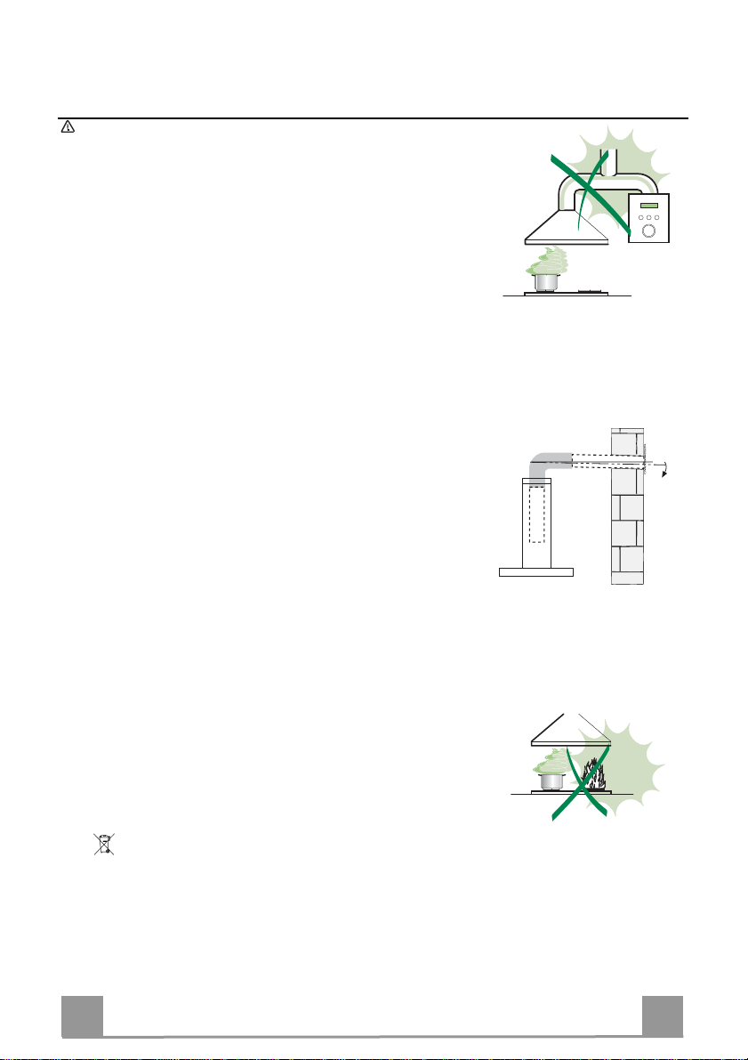
• The minimum safety distance between the cooker top and the extractor hood is 650 mm (some
models can be installed at a lower height, please refer to the paragraphs on working dimensions
and installation).
• Check that the mains voltage corresponds to that indicated on the rating plate fixed to the inside of
the hood.
• For Class I appliances, check that the domestic power supply guarantees adequate earthing.
Connect the extractor to the exhaust flue through a pipe of minimum diameter 120 mm. The route
of the flue must be as short as possible.
• Do not connect the extractor hood to exhaust ducts carrying combustion fumes (boilers, fireplaces,
etc.).
• If the extractor is used in conjunction with non-electrical appliances (e.g. gas burning appliances), a
sufficient degree of aeration must be guarant eed i n the r oom in o rde r to p reve nt the b ackflow of
exhaust gas. The kitchen must have an opening communicating directly with the open air in order
to guarantee the entry of clean air. When the cooker hood is used in conjunction with appliances
supplied with energy other than electric, the negative pressure in the room must not exceed 0,04
mbar to prevent fumes being drawn back into the room by the cooker hood.
• In the event of damage t o the power cable, it must be replaced by the manufacturer or by the
technical service department, in order to prevent any risks.
• If the instructions for installation for the gas hob specify a greater distance specified above, this has
to be taken into account. Regulations concerning the discharge of air have to be fulfilled.
USE
• The extractor hood has been designed exclusively for domestic use to eliminate kitchen smells.
• Never use the hood for purposes other than for which it has been designed.
• Never leave high naked flames under the hood when it is in operation.
• Adjust the flame intensity to direct it onto the bottom of the pan only, making sure that it does not
engulf the sides.
• Deep fat fryers must be continuously monitored during use: overheated oil can burst into flames.
• Do not flambè under the range hood; risk of fire
• This appliance is not intended for use by persons (including children) with reduced physical, sensory or mental capabilities, or lack of experience and knowledge, unless they have been given supervision or instruction concerning use of the appliance by a person responsible for their safety.
• Children should be supervised to ensure that they do not play with the appliance.
• “ CAUTION: Accessible parts may become hot when used with cooking appliances.”.
MAINTENANCE
• Switch off or unplug the applian ce from the mains supply b efore carrying out any mai ntenance
work.
• Clean and/or replace the Filters after the specified time period (Fire hazard).
• Clean the hood using a damp cloth and a neutral liquid detergent.
The symbol on the product or on its packaging indicates that thi s produc t may n ot be treat ed as h ous eho ld was te. In stea d it sh al l be han d ed o ver t o the
applicable collection point for the recycling of electrical and electronic equipment. By ensuring this product is disposed of correctly, you will help prevent potential negative
consequences for the environment and human health, which could otherwise be caused by inappropriate waste handling of this product. For more detailed information
about recycling of this product, please contact your local city office, your household waste disposal service or the shop where you purchased the product
.
EN
3
3
Page 4
CHARACTERISTICS
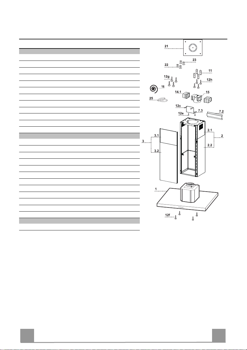
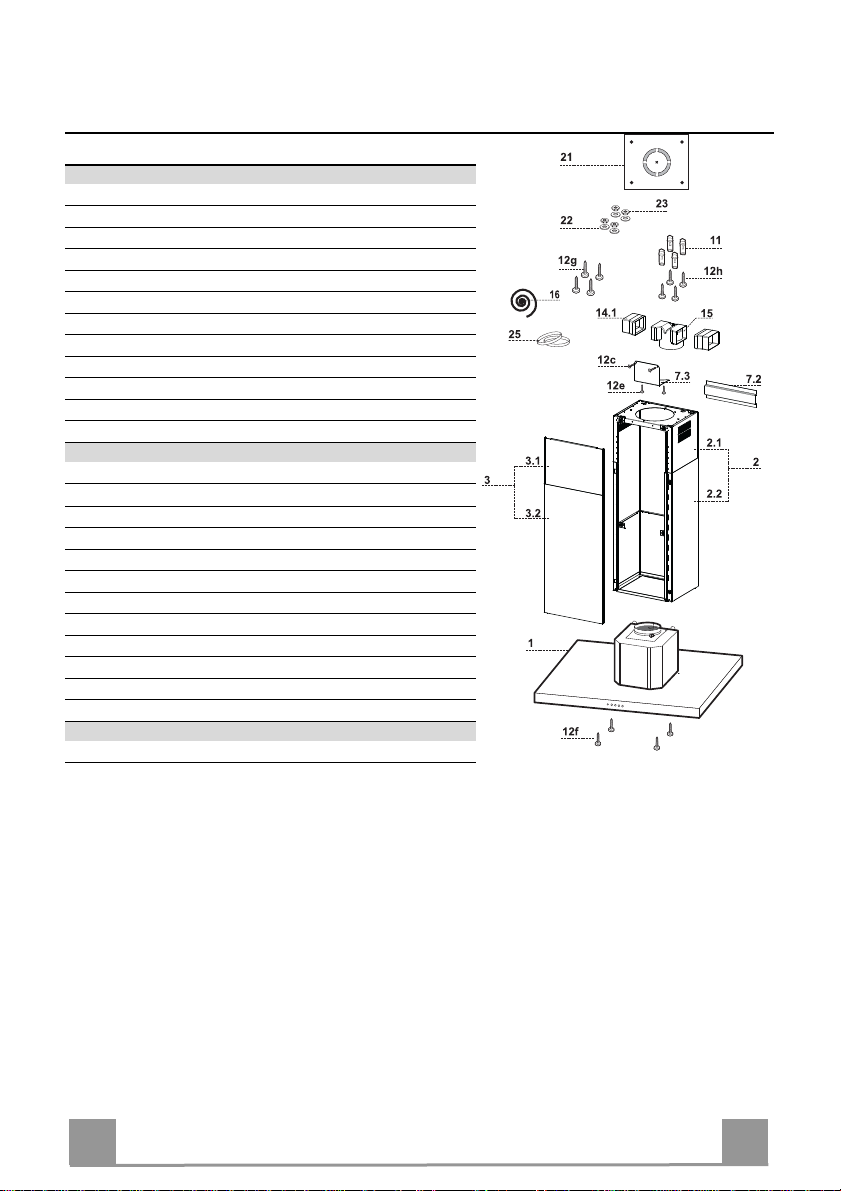
Components
Ref. Q.ty Product Components
1 1 Hood Canopy complete with: Controls, Light, Filters
2 1 Telescopic chimney, made up of:
2.1 1 Upper chimney
2.2 1 Lower chimney
3 1 Telescopic panel, made up of:
3.1 1 Upper panel
3.2 1 Lower panel
14.1 1 Air Outlet Connector Extension
15 1 Air Outlet Connector
16 1 Novastick tape
25 Hose clamps (not supplied)
Ref. Q.ty Installation Components
7.3 1 Air outlet connector fixing bracket
1 Telescopic chimney fixing bracket
7.2
11 4 Wall plugs ø 10
12c 2 Screws 2.9 x 6.5
12e 2 Screws 2.9 x 9.5
12f 4 Screws M4 x 80
12g 4 Screws M6 x 80
12h 4 Screws 5.2 x 70
21 1 Drilling template
22 4 Washers ø 6.4
23 4 Nuts M6
Q.ty Documentation
1 Instruction Manual
EN
4
4
Page 5
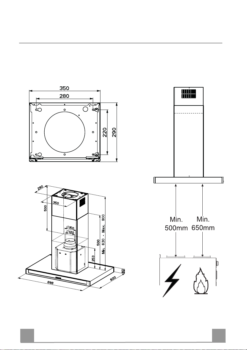
Dimensions
EN
5
5
Page 6
INSTALLATION
Drilling the Ceiling/shelf and fixing the frame
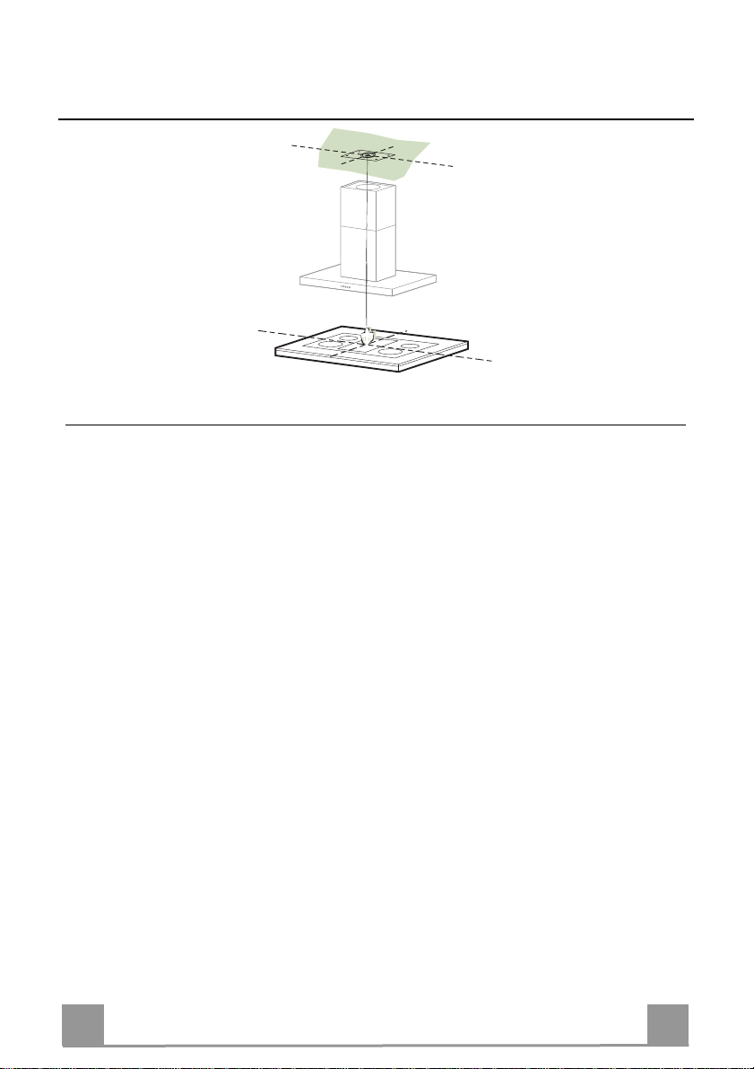
DRILLING THE CEILING/SHELF
• Use a plumb line to mark the centre of the hob on the ceiling/support shelf.
• Place the drilling template 21 provided on the ceiling/support shelf, making sure that the
template is in the correct position by lining up the axes of the template with those of the hob.
• Mark the centres of the holes in the template.
• Drill the holes at the points marked:
• For concrete ceilings, drill for plugs appropriate to the screw size.
• For hollow brick ceilings with wall thickness of 20 mm: drill ø 10 mm(immediately insert
the Dowels 11 supplied).
• For wooden beam ceilings, drill according to the wood screws used.
• For wooden shelf, drill ø 7 mm.
• For the power supply cable feed, drill ø 10 mm.
• For the air outlet (Ducted Version), drill according to the diameter of the external air exhaust duct connection.
• Insert two screws of the following type, crossing them and leaving 4-5 mm from the ceiling:
• For concrete ceilings, use the appropriate plugs for the screw size (not provided).
• for Cavity ceiling with inner space, with wall thickness of approx. 20 mm, Screws 12h,
supplied.
• For wooden beam ceilings, use 4 wood screws (not provided).
• For wooden shelf, use 4 screws 12g with washers 22 and nuts 23, provided.
EN
6
6
Page 7
2
1
2
1
ø 150
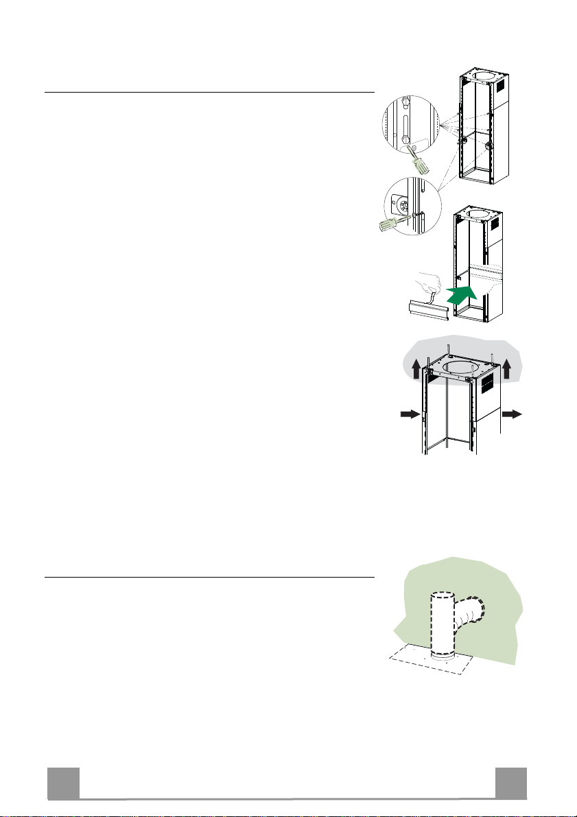
Fixing the Frame/Chimney
Should it be necessary to adjust the height of the frame, proceed
as follows:
• Unfasten the metric screws joining the two opposite parts that
can be seen from the front;
• Adjust the height of the frame as required, then replace the
screws removed as above, making sure that you insert 2 of
them close to the panel lock;
• Lift the frame, insert the slots onto the screws and slide them
until they lock;
• Tighten the two screws and insert the other two screws provided.
• Take the telescopic chimney locking bracket 7.2, remove the
film from the double sided adhesive and fix it inside the frame
so as to hold it more firmly.
Before final locking of the screws it is possible to make small
adjustments to the frame, making sure that the screws do not
come out of the adjustment slot.
• The Frame must be securely fastened both due to the weight of
the Hood and the stress caused by occasional sideways pressure on the Appliance when in position. When fastened, check
that the base is stable even when the Frame is subjected to
bending.
• In all cases where the Ceiling is not sufficiently strong at the
point of suspension, the Installation technician must strengthen
it with suitable plates and counterplates, anchored to structurally sound elements.
Connections
DUCTED VERSION AIR EXHAUST SYSTEM
When installing the ducted version, connect the hood to the
chimney using either a flexible or rigid
pipe ø 150 mm, the choice of which is left to the installer.
• Fix the pipe in position using sufficient pipe clamps (not supplied).
• Remove any activated charcoal filters.
EN
7
7
Page 8
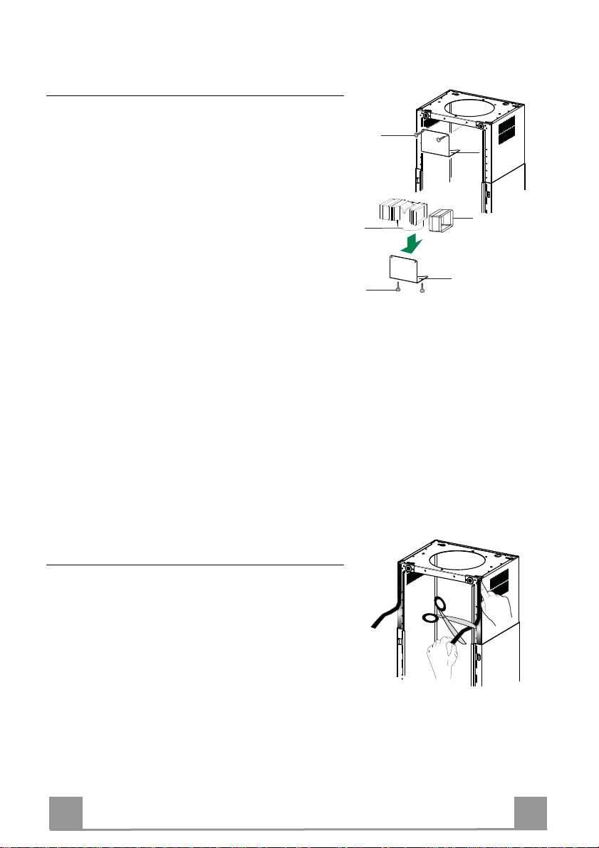
Air outlet – Recirculation Version
• Insert the Connector extensions 14.1 into the side of
the Connector 15.
• Insert the Connector 15 into the Support bracket 7.3
and fix it with the screws.
• Fasten the Support bracket 7.3, fixing it to the upper
part with the Screws.
• Make sure that the Connector extensions outlet 14.1 is
in correspondence with the Chimney openings both
horizontally and vertically.
• Join the Connector 15 to the Hood canopy outlet using
a rigid or flexible pipe ø¸150 mm, selection of which
is at the discretion of the installation technician.
• Make sure that the Activated charcoal odour filter has
been fitted.
12c
7.3
15
12e
14.1
7.3
Application of Novastick Tape
• Apply the Novastick tape 16 to the front edge of the
Upper Chimney from the top part down to the start of
the Lower Chimney.
EN
8
8
Page 9
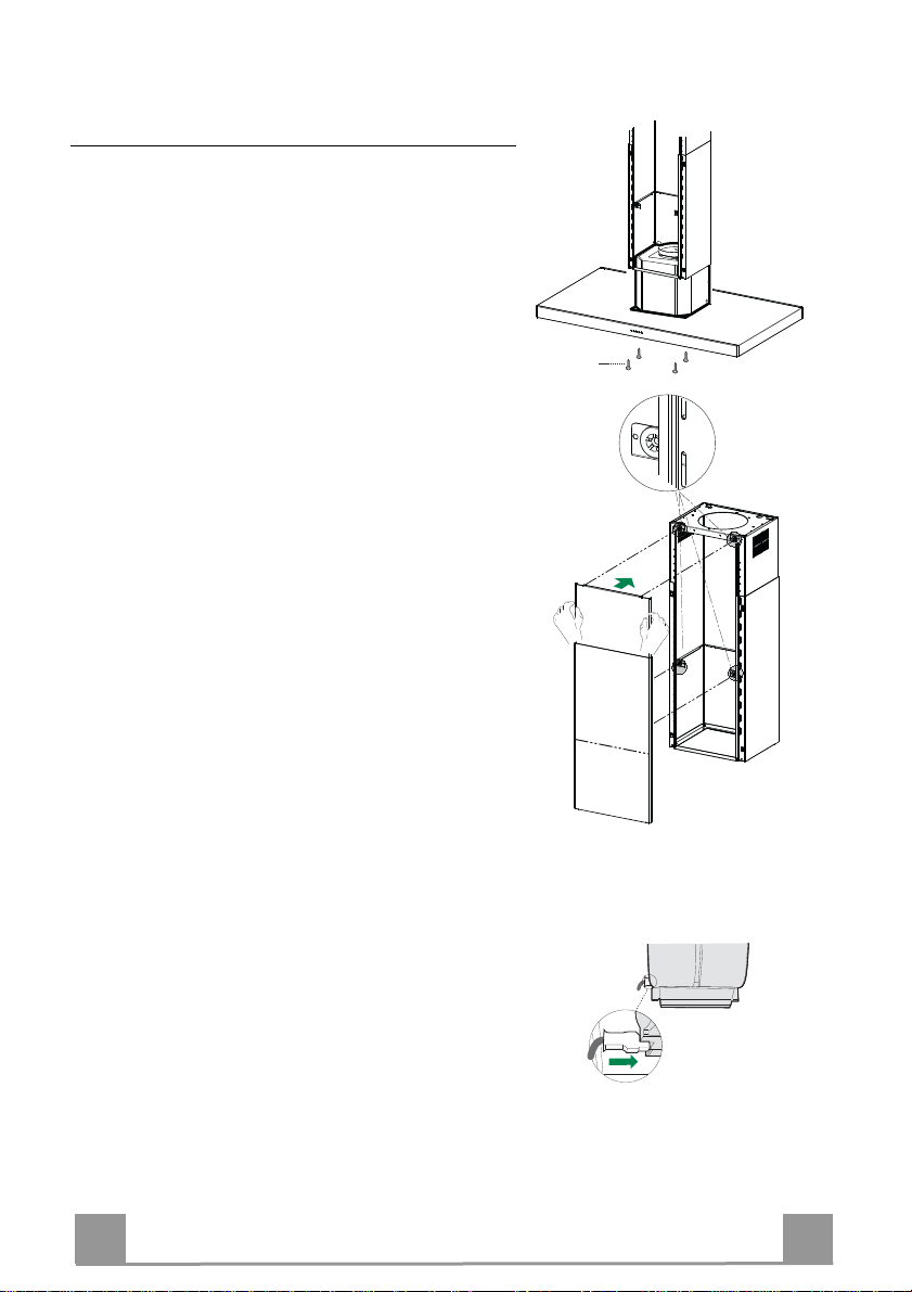
Fitting the Panel and Fixing the Hood Canopy
Before fixing the Hood Canopy to the Frame:
• Remove the Grease filters from the Hood Canopy;
• Remove any Activated charcoal filters.
• Working from below, fix the Hood canopy to the
Frame provided, using the 4 screws 12f (M6 x 10)
provided.
• Then hook the upper part of the Panel 3, adjusted to
size, to the rubber supports in the upper part and in
the lower part of the Frame.
• Slide the lower part of the Panel 3 until its metal tabs
slot into the slots in the frame;
12f
ELECTRICAL CONNECTION
• Connect the hood to the mains through a two-pole
switch having a contact gap of at least 3 mm.
• Remove the grease filters (see paragraph Maintenance) being sure that the connector of the feeding
cable is correctly inserted in the socket placed on the
side of the fan.
EN
9
9
Page 10
USE
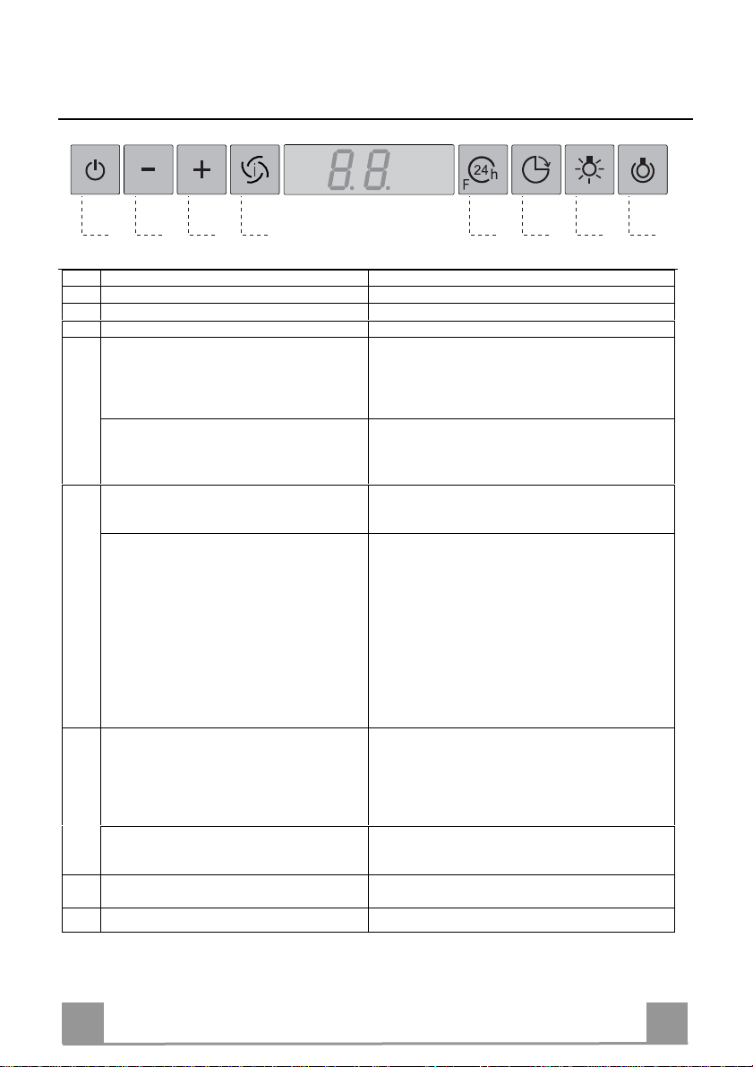
A B C D E F G H
Control panel
Button Function Display
A Turns the suction motor on and off at speed one. Displays the set speed
B Decreases the working speed. Displays the set speed
C Increases the working speed. Displays the set speed
D Activate intensive speed from any other speed,
including motor off. This speed is set to operate
for 10 minutes, after which the system returns to
the speed that was set before. Suitable to deal with
maximum levels of cooking fumes.
Press and hold the button for approximately 5
seconds, with all the loads turned off (Motor and
Lights), to turn the Activated Charcoal Filter
alarm On and Off.
E 24H function
Turns the suction motor on at speed one and
effects one 10 minute extraction every hour.
When the filters alarm is triggered, the alarm can
be reset by pressing and holding this button for
approximately 3 seconds.
These indications are only visible when the motor
is turned off.
F Delay function
Activate automatic switch-off with a 30’ delay.
Suitable to complete elimination of residual
odours. Can be activated from any position, and is
disabled by pressing the button or turning the
motor off.
Press and hold the button for approximately 5
seconds, with all the loads turned off (Motor and
Lights), to turn the Remote Control On and Off.
G Turns the lighting system on and off at maximum
intensity.
H Turns the Courtesy Lighting on and off.
EN
Displays HI and the time remaining once very second.
FC+Punto (2 flashes)–Alarm On.
FC+Punto (1 flash)–Alarm Off.
Displays 24 and the spot at the bottom right flashes once
every second, while the motor is running.
It is disabled by pressing the button.
FF flashes three times.
When the procedure terminates, the indication shown
previously turns off:
FG indicates the need to wash the metal grease filters.
The alarm is triggered after the Hood has been in
operation for 100 working hou r s.
FC indicates the need to change the activated charcoal
filters, and also to wash the metal grease filters. The alarm
is triggered after the Hood has been in operation for 200
working hours.
Displays the operating speed and the spot at the bottom
right flashes once a second.
IR+Punto (2 flashes)–Alarm On.
IR+Punto (1 flash)–Alarm Off.
1
10
Page 11
MAINTENANCE
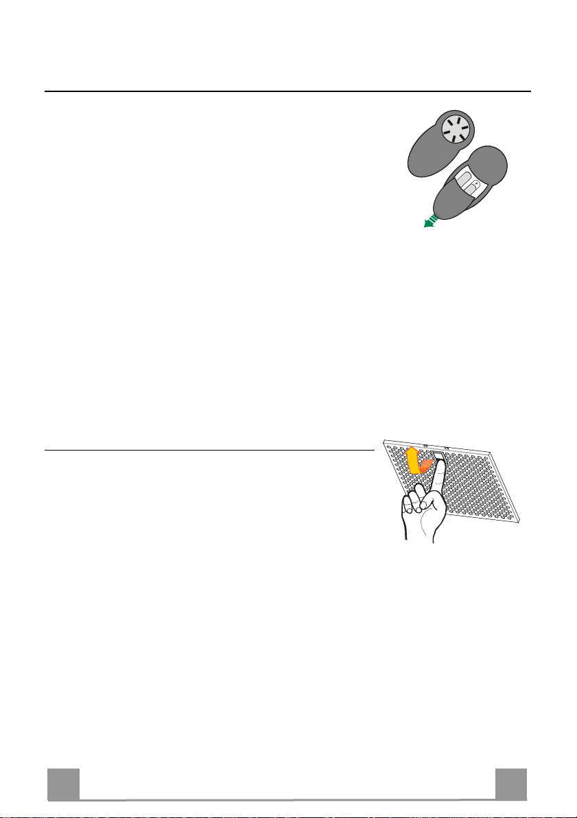
REMOTE CONTROL (OPTIONAL)
The appliance can be controlled using a remote control powered
by a 1.5 V carbon-zinc alkaline batteries of the standard LR03AAA type (not included).
• Do not place the remote control near to heat sources.
• Used batteries must be disposed of in the proper manner.
Metal grease filters
They can be washed in the dishwasher, and need to be cleaned
whenever the FG sign appears on the display or at least once
every 2 months use, or more frequently if use is particularly
intensive.
Resetting the alarm signal
• Turn the Lights and the Suction motor off, then disable the 24h
function, if enabled.
• Press button E (see the paragraph on Use).
Cleaning the Filters
• Remove the filters one at a time holding them up with one
hand and pulling the handle downwards with the other hand at
the same time.
• Wash the Filters without bending them, and leave them to dry
completely before replacing. (If the surface of the filter
changes colour as time goes by, this will have absolutely no
effect on the efficiency of the filter itself.)
• Replace, taking care to ensure that the handle faces forwards.
EN
1
11
Page 12
Activated Charcoal Filter (Recirculation Version)
It cannot be washed or regenerated, and must be changed when the FC symbol on the display
appears, or at least once every 4 months. The Alarm signal, if it has been activated, only
appears when the Suction motor is turned on.
Activating the alarm signal
• In Recirculation Version Hoods, the Filter Saturation Alarm must be activated on
installation or at a later date.
• Turn the Lights and the Suction Motor off.
• Press D and hold for approximately 5 Seco nds:
• The message FC+Puntino flashes twice, A.C. Filter satu ra tion alarm ACTIVATED
• The message FC+Puntino flashes once, A.C. Filter saturation alarm DEACTIVATED
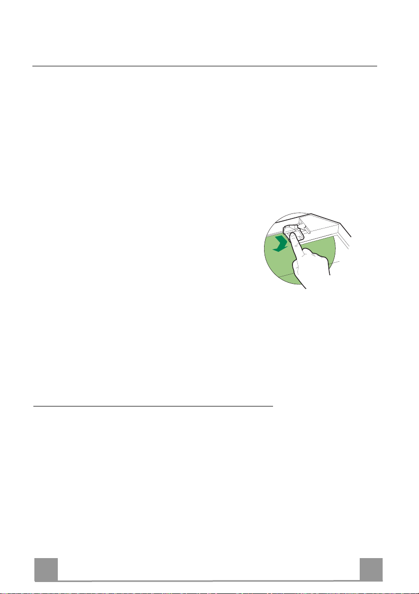
CHANGING THE ACTIVATED CHARCOAL FILTER
Resetting the alarm signal
• Turn the Lights and the Suction Motor off.
• Press button E and hold for approximately 5 sec-
onds (See paragraph on Use).
Changing the Filter
• Remove the Metal grease filters.
• Remove the Suction Panel by unfastening the 4
screws at the corners.
• Remove the saturated Activated charcoal filter,
using the hooks provided.
• Fit the new Filter, hooking it into place.
• Replace the Panel and the Metal grease filters.
Lighting unit
Warning: This appliance is fitted with a white LED lamp classed
as 1M according to EN 60825-1: 1994 + A1:2002 + A2:2001
standards; maximum optical power emitted @439nm: 7µW. Do
not look directly at the light through optical devices (binoculars,
magnifying glasses…).
• For replacement contact technical support. ("To purchase contact technical support")
EN
1
12
Page 13

2°
CONSIGLI E SUGGERIMENTI
Questo libretto di istruzio ni per l'uso è previsto per più versioni dell' apparecc hio. É possibile che siano
descritti singoli particolari della dotazione, che non riguardano il Vostro apparecchio.
INSTALLAZIONE
• Il produttore declina qualsiasi responsabilità per danni dovuti ad installazione non corretta o non conforme
alle regole dell’arte.
• La distanza minima di sicu re zz a tra il Pi ano di co ttura e l a C ap pa d eve e sse re d i 650 mm , (a lcun i mod elli
possono essere installati ad un’altezza inferiore, fare riferimento ai paragrafi ingombro e installazione).
• Verificare che la tensione di rete corrisponda a quella riportata nella targhetta posta all’interno della Cappa.
• Per Apparecchi in Classe I
terra.
• Colleg are la Cappa all’ uscita dell’ar ia aspirata con t ubazione di diamet ro pari o superior e a 120 mm. Il
percorso della tubazione deve essere il più breve possibile.
• Non collegare la Cappa a condotti di scarico dei fumi prodotti da combustione (caldaie, caminetti, ecc.).
• Nel caso in cui nella stanza vengano utilizzati sia la Cappa che apparecchi non azionati da energia elettrica
(ad esempio apparecchi utilizzatori di gas), si deve provvedere ad una aerazione sufficiente dell’ambiente.
Se la cucina ne fosse sprovvista, praticare un’apertura che comunichi con l’esterno, per garantire il richiamo d’aria pulita. Un uso proprio e senza rischi si ottiene quando la depressione massima del locale non
supera i 0,04 mBar.
• In caso di danneggiamento del cavo alimentazione, esso deve essere sostituito dal costruttore o dal servizio di assistenza tecnica, in modo da prevenire ogni rischio.
• Se le istruzioni di installazione del dispos itivo di cottura a gas indican o che è necessaria una distanza
maggiore di quella indicato sopra, è necessario tenerne conto. Bisogna rispettare tutte le normative relative
allo scarico dell’aria.
USO
• La Cappa è stata progettata esclusivamente per uso domestico, per abbattere gli odori della cucina.
• Non fare mai uso improprio della Cappa.
• Non lasciare fiamme libere a forte intensità sotto la Cappa in funzione.
• Reg olare sempr e le fiamm e in modo da evit are una evi dente fuor iuscita lat erale dell e stesse risp etto al
fondo delle pentole.
• Controllare le friggitrici durante l’uso: l’olio surriscaldato potrebbe infiammarsi.
• Non preparare alimenti flambè sotto la cappa da cucina; pericolo d'incendio.
• Questo apparecchio non deve essere utilizzato da persone (bambini inclusi) con ridotte capacità psichiche,
sensoriali o mentali, oppure da persone senza esperienza e conoscenza, a meno che non siano controllati
o istruiti all’uso dell’apparecchio da persone responsabili della loro sicurezza.
• I bambini devono essere supervisionati per assicurarsi che non giochino con l’apparecchio.
• “ATTENZIONE: Le parti accessibili p ossono divent are molto ca lde se util izzate con deg li apparecch i di
cottura”.
MANUTENZIONE
• Prima di procedere a qualsiasi operazione di manutenzione, disinserire la Cappa togliendo la spina elettrica o spegnendo l’interruttore generale.
• Effettuare una scrupolosa e tempestiva manutenzione dei Filtri second o gli intervalli consigliati (Risc hio di
incendio).
• Per la pulizia delle superfici della Cappa è sufficiente utilizzare un panno umido e detersivo liquido neutro.
a
accertarsi che l’impianto elettrico d omestic o garant isca un co rretto sca rico a
Il simbolo sul prodotto o sulla confezione indica che il prodotto non deve essere considerato come un normale
rifiuto domestico, ma deve essere portato nel punto di raccolta appropriato per il riciclaggio di apparecchiature elettriche
ed elettroniche. Provvedendo a smaltire questo prodo tto in modo appropr ia to, si con tribuisce a evitare potenz iali conseguenze negative per l’ambiente e per la salute, che potrebbero derivare da uno smaltimento inadeguato del prodotto.
Per informazioni più dettagliate sul riciclaggio di questo prodotto, contattare l’ufficio comunale, il servizio locale di smaltimento rifiuti o il negozio in cui è stato acquistato il prodotto.
IT
1
13
Page 14
CARATTERISTICHE
Componenti
Rif. Q.tà Componenti di Prodotto
1 1 Corpo Cappa completo di: Comandi, Luce, Filtri
2 1 Camino telescopico formato da:
2.1 1 Camino superiore
2.2 1 Camino inferiore
3 1 Pannello telescopico formato da:
3.1 1 Pannello superiore
3.2 1 Pannello inferiore
14.1 1 Prolunga Raccordo Uscita Aria
15 1 Raccordo Uscita Aria
16 1 Nastro Novastick
25 Fascette stringitubo (non incluse)
Rif. Q.tà Componenti di Installazione
7.3 1 Staffa fissaggio raccordo uscita aria
7.2
1 Staffa bloccaggio camino telescopico
11 4 Tasselli ø 10
12c 2 Viti 2,9 x 6,5
12e 2 Viti 2,9 x 9,5
12f 4 Viti M4 x 80
12g 4 Viti M6 x 80
12h 4 Viti 5,2 x 70
21 1 Dima di foratura
22 4 Rondelle ø 6,4
23 4 Dadi M6
Q.tà Documentazione
1 Libretto Istruzioni
IT
1
14
Page 15

Ingombro
IT
1
15
Page 16

INSTALLAZIONE
Foratura Soffitto/Mensola e Fissaggio Traliccio
FORATURA SOFFITTO/MENSOLA
• Con l’ausilio di un Filo a piombo riportare sul Soffitto/Mensola di supporto il centro del
Piano di Cottura.
• Appoggiare al Soffitto/Mensola la Dima di Foratura 21 in dotazione, facendo coincidere il
suo centro al centro proiettato e allineando gli assi della Dima agli assi del Piano di Cottura.
• Segnare i centri dei Fori della Dima.
• Forare i punti seguenti:
• Soffitto in Calcestruzzo massiccio: secondo Tasselli per Calcestruzzo impiegati.
• Soffitto in Laterizio a camera d’aria, con spessore resistente di 20 mm: ø 10 mm (inserire
subito i Tasselli 11 in dotazione).
• Soffitto in Travatura di Legno: secondo Viti per Legno impiegate.
• Mensola in Legno: ø 7 mm.
• Passaggio del Cavo elettrico di Alimentazione: ø 10 mm.
• Uscita Aria (Versione Aspirante): secondo diametro del collegamento alla Tubazione di
Evacuazione Esterna.
• Avvitare, incrociandole e lasciando 4-5 mm dal soffitto, due viti:
• per Calcestruzzo massiccio, Tasselli per Calcestruzzo, non in dotazione.
• per Laterizio a camera d’aria, con spessore resistente di 20 mm circa, Viti 12h, in dotazio-
ne.
• per Travatura di legno, Viti per legno, non in dotazione.
• per Mensola in Legno, viti 12g con Rondelle 22 e Dadi 23, in dotazione.
IT
1
16
Page 17

2
1
2
1
ø 150
Fissaggio Traliccio/Camino
Nel caso in cui si voglia regolare l’altezza del traliccio procedere
come segue:
• Svitare le viti metriche che uniscono le due parti di fronte visibili frontalmente;
• Regolare l’altezza desiderata del traliccio e riavvitare le viti
precedentemente tolte, avendo l’accortezza di metterne 2 in
prossimità del blocco pannello;
• Sollevare il traliccio, incastrare le asole sulle viti e scorrere
fino a battuta;
• Stringere le due viti e avvitare le altre due in dotazione;
• Prendere la staffa bloccaggio camino telescopico 7.2, togliere
la pellicola del biadesivo e attaccarla internamente al traliccio
in modo da tenerlo più fisso.
Prima di serrare definitivamente le viti è possibile effettuare delle
regolazioni spostando il traliccio facendo attenzione che le viti
non escano dalla sede dell’asola di regolazione.
• Il fissaggio del Traliccio deve essere sicuro in relazione sia al
peso della Cappa sia alle sollecitazioni causate da occasionali
spinte laterali all’Apparecchio montato. A fissaggio avvenuto
verificare quindi che la base sia stabile anche se il Traliccio è
sollecitato a flessione.
• In tutti i casi in cui il Soffitto non fosse sufficientemente robusto sul punto di sospensione, l’Installatore dovrà provvedere a
irrobustirlo con opportune piastre e contropiastre ancorate a
parti strutturalmente resistenti.
Connessioni
USCITA ARIA VERSIONE ASPIRANTE
Per installazione in Versione Aspirante collegare la Cappa alla
tubazione di uscita per mezzo di un tubo rigido o flessibile di
ø150 la cui scelta è lasciata all'installatore.
• Fissare il tubo con adeguate fascette stringitubo. Il materiale
occorrente non è in dotazione.
• Togliere eventuali Filtri Antiodore al Carbone attivo.
IT
1
17
Page 18

Uscita aria Versione Filtrante
• Inserire lateralmente le Prolunghe Raccordo 14.1 sul
Raccordo 15.
• Inserire il Raccordo 15 nella Staffa di Sostegno 7.3
fissandolo con le Viti.
• Fissare la Staffa di Sostegno 7.3 fissandola con le
Viti alla parte superiore.
• Assicurarsi che l’uscita delle Prolunghe Raccordo
14.1 risulti in corrispondenza delle bocchette del
Camino sia in orizzontale che in verticale.
• Collegare il Raccordo 15 all’Uscita del Corpo Cappa
per mezzo di un tubo rigido o flessibile di ø150
mm, la cui scelta è lasciata all'installatore.
• Assicurarsi della presenza del Filtro Antiodore al
Carbone attivo.
12c
7.3
15
12e
14.1
7.3
Applicazione Nastro Novastick
• Applicare il nastro Novastick 16 sul bordo frontale
del Camino Superiore dalla parte superiore fino
all’inizio del Camino Inferiore.
IT
1
18
Page 19

Montaggio Pannello e Fissaggio Corpo Cappa
Prima di fissare il Corpo Cappa al Traliccio:
• Togliere i Filtri antigrasso dal Corpo Cappa;
• Togliere eventuali Filtri Antiodore al Carbone attivo.
• Fissare quindi dal sotto, con 4Viti 12f (M6 x 10) in
dotazione, il Corpo Cappa al Traliccio predisposto.
• Successivamente agganciare la parte superiore del
Pannello 3,regolato a misura, sui supporti di gomma
presenti nella parte superiore del Traliccio e anche in
quella inferiore;
• Scorrere la parte inferiore del Pannello 3 finchè le
sue linguette metalliche non si incastrano sulle asole
del traliccio;
12f
CONNESSIONE ELETTRICA
• Collegare la Cappa all’Alimentazione di Rete interponendo un Interruttore bipolare con apertura dei
contatti di almeno 3 mm.
• Rimuovere i Filtri antigrasso (vedi par. “Manutenzione”) e assicurarsi che il connettore del Cavo di alimentazione sia correttamente inserito nella presa
dell’Aspiratore
IT
1
19
Page 20

USO
A B C D E F G H
Quadro comandi
Tasto Funzione Display
A Accende e spegne il motore di aspirazione alla prima
velocità.
B Decrementa la velocità di esercizio. Visualizza la velocità impostata
C Incrementa la velocità di esercizio. Visualizza la velocità impostata
D Attiva la velocità Intensiva da qualsiasi velocità
anche da motore spento, tale velocità è temporizzata a
10 minuti, al termine del tempo il sistema ritorna alla
velocità precedentemente impostata. Adatta a fronteggiare le massime emissioni di fumi di cottura.
Tenendo il tasto premuto per circa 5 secondi, quando
tutti i carichi sono spenti (Motore+Luce), si Attiva /
Disattiva l’allarme dei Filtri al Carbone attivo.
E Funzione 24H
Attiva il motore alla prima velocità e consente
un’aspirazione di 10 minuti ogni ora.
Con l’allarme filtri in corso premendo il tasto per
circa 3 secondi si effettua il reset dell’allarme.
Tali segnalazioni sono visibili solo a motore spento.
F Funzione Delay
Attiva lo spegnimento automatico ritardato di 30’.
Adatto per completare l’eliminazione di odori residui.
Attivabile da qualsiasi posi zione, si disattiva premendo il tasto o spegnendo il motore.
Tenendo il tasto premuto per circa 5 secondi, quando
tutti i carichi sono spenti (Motore+Luce), si Attiva /
Disattiva il Telecomando.
G Accende e spegne l’impianto di illuminazione alla
massima intensità.
H Accende e spegne l’impianto di illuminazione in
modalità Luce di Cortesia.
Visualizza la velocità impostata
Visualizza alternamente HI e il tempo rimanente una
volta al secondo.
FC+Punto (2Lampeggi)–Allarme Attivo.
FC+Punto (1Lampeggio)–Allarme Disattivo.
Visualizza 24 e il punto in basso a destra lampeggia una
volta al secondo, mentre il motore è in funzione.
Si disabilita premendo il tasto.
Lampeggia FF tre volte.
Terminata la procedura si spegne la segnalazione precedentemente visualizzata:
FG segnala la necessità di lavare i filtri antigrasso metallici. L’allarme entra in funzione dopo 100 ore di lavoro
effettivo della Cappa.
FC segn ala la necessità di sostituire i filtri al carbo ne
attivo e devono anche essere lavati i filtri antigrasso metallici. L’allarme entra in funzione dopo 200 ore di lavoro
effettivo della Cappa.
Visualizza la velocità di esercizio e il punto in basso a
destra lampeggia una volta al secondo.
IR+Punto (2Lampeggi)–Allarme Attivo.
IR+Punto (1Lampeggio)–Allarme Disattivo.
IT
2
20
Page 21

MANUTENZIONE
TELECOMANDO (OPZIONALE)
Questo apparecchio può essere comandato per mezzo di un telecomando, alimentato con pile alcaline zinco-carbone da 1,5 V del
tipo standard LR03-AAA (non incluse).
• Non riporre il telecomando in prossimità di fonti di calore.
• Non disperdere le pile nell’ambiente, depositarle negli appositi
contenitori.
Filtri antigrasso metallici
Sono lavabili anche in lavastoviglie, e necessitano di essere lavati
quando sul display appare FG o almeno ogni 2 mesi circa di utilizzo o più frequentemente, per un uso particolarmente intenso.
Reset del segnale di allarme
• Spegnere le Luci e il Motore di aspirazione, quindi qualora
fosse attivata la funzione 24h disattivarla.
• Premere il tasto E (Vedi paragrafo Uso).
Pulizia Filtri
• Togliere i Filtri uno alla volta,sostenendoli con una mano mentre con l’altra si tira la leva verso il basso.
• Lavare i Filtri evitando di piegarli, e lasciarli asciugare prima
di rimontarli. (Un’eventuale cambiamento del colore della superficie del filtro, che potrebbe verificarsi nel tempo, non pregiudica assolutamente l’efficienza dello stesso.)
• Rimontarli facendo attenzione a mantenere la maniglia verso la
parte visibile esterna.
IT
2
21
Page 22

Filtri antiodore al Carbone attivo (Versione Filtrante)
Non è lavabile e non è rigenerabile, va sostituito quando sul display appare FC o almeno ogni
4 mesi. La segnalazione di Allarme, se preventivamente attivata, si verifica solo quando è azionato il Motore di aspirazione.
Attivazione del segnale di allarme
• Nelle Cappe in Versione Filtrante, la segnalazione di Allarme saturazione Filtri va attivata al
momento dell’installazione o successivamente.
• Spegnere le Luci e il Motore di aspirazione.
• Premere il tasto D per circa 5 Secondi:
• 2 Lampeggi scritta FC+Puntino -- Allarme saturazione Filtro C.A. ATTIVATO.
• 1 Lampeggio scritta FC+Puntino -- Allarme saturazione Filtro C.A. DISATTI VAT O.
SOSTITUZIONE FILTRO ANTIODORE AL CARBONE ATTIVO
Reset del segnale di allarme
• Spegnere le Luci e il Motore di aspirazione.
• Premere il tasto E per circa 5 secondi (Vedi paragrafo Uso).
Sostituzione Filtro
• Togliere i Filtri antigrasso metallici.
• Togliere il Pannello di Aspirazione svitando le 4 Viti sugli angoli.
• Rimuovere il Filtro antiodore al Carbone attivo saturo, agendo
sugli appositi agganci.
• Montare il nuovo Filtro agganciandolo nella sua sede.
• Rimontare il Pannello e i Filtri antigrasso metallici.
Illuminazione
Attenzione: Questo apparecchio è provvisto di una luce LED
bianca di classe 1M secondo la norma EN 60825-1: 1994 +
A1:2002 + A2:2001; massima potenza ottica emessa@439nm:
7µW. Non osservare direttamente con strumenti ottici (binocolo,
lente d’ingrandimento….).
• Per la sostituzione contattare l’Assistenza Tecnica. ("Per l'acquisto rivolgersi all'assistenza tecnica").
IT
2
22
Page 23

2°
CONSEILS ET SUGGESTIONS
La présente notice d'emploi vaut pour plusieurs versions de l'appareil. Elle peut contenir des descriptions d'ac-
cessoires ne figurant pas dans votre appa reil.
INSTALLATION
• Le fabricant décline toute responsabilité en cas de dommage dû à une installation non correcte ou non
conforme aux règles de l’art.
• La distance minimale de sécurité entre le plan de cuisson et la hotte doit être de 650 mm au moins (ce rtains
modèles peuvent être installés à une hauteur inférieure : se reporter aux paragraphes « Encombrement » et
« Installation ») .
• Vérifier que la tension du secteur correspond à la valeur qui figure sur la plaquette apposée à l’intérieur de la
hotte.
• Pour les Appareils appartenant à la Ière Classe, veiller à ce que la mise à la terre de l’installation électrique
domestique ait été effectuée conformément aux normes en vi gueur.
• Connecter la hotte à la sortie d’air aspiré à l’aide d’une tuyauterie d’un diamètre égal ou supérieur à 120 mm. Le
parcours de la tuyauterie doit être le plus cou rt possible.
• Ne pas connecter la hotte à des conduites d’évacuation de fumées issues d’une combustion tel que (Chaudière, cheminée, etc…).
• Si vous utilisez des appareils qui ne fonctionnent pas à l’électricité dans la pièce ou est installée la hotte (par
exemple: des appareils fonctionnant au gaz), vous devez prévoir une aération suffisan te du milieu. Si la cuisine
en est dépourvue, pratiquez une ouverture qui com munique avec l’extérieur pour ga rantir l’infiltration de l’air pur.
Pour un emploi correct et sans risque, la dépression maximum dans la pièce ne doit pa s dépasser 0,04 mbar.
• En cas d’endommagement du cordon d’alimentation, faites-le re mpla cer par le constructeur ou par le service
après-vente, afin de prévenir tout risque.
• Si les instructions de montage pour la plaque de cuisson au gaz spécifient une plus grande distance indiquée cidessus, cela doit être pris en compte. Règlemen t concernant l'évacuation d'air doivent être remplies..
UTILISATION
• La hotte a été conçue exclusivement pour l’usage domestique, dans le but d’éliminer les odeurs de la cuisine.
• Ne jamais utiliser abusivement la hotte.
• Ne pas laisser les flammes libres à forte intensité quand la hotte est en service.
• Toujours régler les flammes de manière à éviter toute sortie latérale de ce s derniè res par rappo rt au fond des
marmites.
• Contrôler les friteuses lors de l’utilisation car l’huile surchauffée pourrait s’enflammer.
• Ne pas préparer d’aliments flambés sous la hotte de cuisine : risque d’incendie
• Cet appareil ne doit pas être utilisé par des personnes (y compris les enfants) ayant des capacités psychiques ,
sensorielles ou mentales réduites, ni par des personnes n’ ayant pas l’expérience et la connaissance de ce type
d’appareils, à moins d'être sous le contrôle e t la formation de personn es responsables de leur sécurité.
• Les enfants doivent être surveillés pour s'assurer qu'ils ne jouent pas avec l'appareil .
• « ATTENTION : Les parties accessibles peuvent devenir très chaudes si u tilisées avec des appa reils de cuis-
son. »
ENTRETIEN
• Avant de procéder à toute opération d’entretien, retirer la hotte en retirant la fiche ou en actionnant l’interrupteur
général.
• Effectuer un entretien scrupuleux et en temps dû des Filtres, à la cadence conseillée (Risque d’in cendie).
• Pour le nettoyage des surfaces de la hotte, il suffit d’utiliser un chiffon humide et détersif li quide neutre.
Le symbole sur le produit ou son emballage indique que ce produit ne peut être traité comme déchet ménager. Il
doit plutôt être remis au point de ra massage conc erné, se char geant du recyc lage du ma tériel électr ique et élec tronique.
En vous assurant que ce produit est éliminé correctement, vous favorisez la prévention des conséquences négatives
pour l’environnement et la santé humaine qui, sinon, seraient le résultat d’un traitement inapproprié des déchets de ce
produit. Pour obtenir plus de détails sur le recyc lage de ce produ it, ve uillez prendr e con tact av ec le bur eau mu nicipa l de
votre région, votre service d’élimination des déchets ménagers ou le magas in où vous avez ac heté le produit.
FR
2
23
Page 24

CARACTERISTIQUES
Composants
Réf. Q.té Composants du produit
1 1 Corps de hotte comprenant : Commandes, Éclairage,
2 1 Conduit télescopique constitué de :
2.1 1 Conduit supérieur
2.2 1 Conduit inférieur
3 1 Conduit télescopique constitué de:
3.1 1 Panneau supérieur
3.2 1 Panneau inférieur
14.1 1 Rallonge raccord de sortie de l’air
15 1 Raccord de sortie de l’air
16 1 Bande Novastick
25 Colliers serre-tube (non compris)
Réf. Q.té Composants d’installation
7.3 1 Bride de serrage raccord sortie air
7.2
11 4 Chevilles ø 10
12c 2 Vis 2,9 x 6,5
12e 2 Vis 2,9 x 9,5
12f 4 Vis M4 x 80
12g 4 Vis M6 x 80
12h 4 Vis 5,2 x 70
21 1 Gabarit de perçage
22 4 Rondelles ø 6,4
23 4 Écrous M6
Q.té Documentation
1 Manuel d’instructions
Filtres
1 Bride de serrage conduit télescopique
FR
2
24
Page 25

Encombrement
FR
2
25
Page 26

INSTALLATION
Perçage Plafond/Étagère et Fixation Treillis
PERÇAGE PLAFOND/ETAGERE
• À l’aide d’un Fil à plomb, reporter sur le Plafond/Étagère de support le centre du Plan de
Cuisson.
• Poser contre le Plafond/Étagère le Gabarit de Perçage 21 fourni avec l’appareil, en faisant
coïncider son centre avec le centre projeté et en alignant les axes du Gabarit avec les axes du
Plan de Cuisson.
• Marquer les centres des Trous du Gabarit.
• Percer les trous qui ont été marqués:
• Plafond en Béton massif: en fonction des Goujons pour Béton utilisés.
• Plafond en Briques avec chambre à air, avec épaisseur résistante de 20 mm: ø 10 mm (in-
sérer immédiatement les Chevilles 11 fournies avec l’appareil).
• Plafond en Poutrage en Bois: en fonction des Vis à Bois utilisées.
• Étagère en Bois: ø 7 mm.
• Passage du Câble électrique d’Alimentation: ø 10 mm.
• Sortie Air (Version Aspirante): en fonction du diamètre de la connexion avec les Tuyaux
d’Évacuation Externe.
• Visser deux vis en les croisant et en laissant 4-5 mm. de distance par rapport au plafond:
• pour le Béton massif, des Goujons pour Béton, non fournis avec l’appareil.
• pour Briques percées, ayant une épaisseur résistante de 20 mm. environ, utiliser les Vis
12h, fournies avec l'appareil.
• pour le Poutrage en bois, 4 Vis à bois, non fournies avec l’appareil.
• pour l’Étagère en Bois, 4 Vis 12g avec Rondelles 22 et Écrous 23, fournis avec l’appareil.
FR
2
26
Page 27

2
1
2
1
ø 150
Fixation Treillis/Conduit
Au cas où l’on souhaiterait régler la hauteur du treillis, suivre la
marche ci-dessous :
• Desserrer les vis métriques d’assemblage des deux parties frontales visibles par la partie avant ;
• Régler la hauteur désirée du treillis et resserrer les vis précédemment retirées, en ayant soin d’en placer 2 à proximité du
blocage du panneau ;
• Soulever le treillis, emboîter les fentes sur les vis et faire coulisser jusqu'en butée ;
• Serrer les deux vis et visser les deux autres vis fournies.
• Saisir la bride de serrage du conduit télescopique 7.2, retirer le
film biadhésif et le coller intérieurement au treillis de manière
à ce qu’il soit plus solide.
Avant de serrer définitivement les vis, on pourra effectuer des
réglages en déplaçant le treillis, en veillant à ce que les vis ne sortent pas du logement de la fente de réglage.
• La fixation du treillis doit être ferme tant par rapport au poids
de la hotte qu’en ce qui concerne les contraintes résultant des
poussées latérales occasionnelles subies par l’appareil une fois
monté. Une fois fixé, vérifier que la base est stable même si le
treillis fait l'objet d’efforts en flexion.
• Dans tous les cas où le plafond n'est pas suffisamment robuste
au point de suspension, le monteur devra prendre des mesures
pour le renforcer avec des plaques et contreplaques appropriées, ancrées sur des parties structurellement résistantes.
Branchements
SORTIE AIR VERSION ASPIRANTE
En cas d’installation en version aspirante, brancher la hotte à la
tuyauterie de sortie via un tube rigide ou flexible de ø 150 mm,
au choix de l’installateur.
• Fixer le tube par des colliers appropriés. Le matériau nécessaire n’est pas fourni.
• Retirer les éventuels filtres anti-odeur au charbon actif.
FR
2
27
Page 28

Sortie de l’air version filtrante
• Monter latéralement les rallonges du raccord 14.1
sur le raccord 15 ;
• Placer le raccord 15 dans l’étrier de soutien 7.3 en le
fixant avec les vis ;
• Fixer l’étrier de soutien 7.3 en le fixant avec les vis à
la partie supérieure.
• S’assurer que la sortie des rallonges du raccord 14.1
se trouve en face des ouvertures du conduit, aussi
bien horizontalement que verticalement ;
• Raccorder le raccord 15 à la sortie du corps de hotte
au moyen d’un tuyau rigide ou flexible de 150 mm
de diamètre, au choix de l'installateur ;
• S’assurer de la présence du filtre anti-odeur au charbon actif.
12c
7.3
15
12e
14.1
7.3
Application Bande Novastick
• Appliquer la bande Novastick 16 sur le bord frontal
du conduit supérieur en partant du haut jusqu’au début du conduit inférieur.
FR
2
28
Page 29

Montage du panneau et fixation du corps de hotte
Avant de fixer le corps de hotte au treillis :
• Retirer les filtres à graisse du corps de hotte.
• Retirer les éventuels filtres anti-odeur au charbon
actif.
• En passant par-dessous, fixer ensuite le corps de
hotte au treillis, avec les 4 vis 12f fournies (M6 x 10).
• Accrocher ensuite la partie supérieure du panneau 3,
réglé sur mesure, sur les supports en caoutchouc présents dans la partie supérieure du treillis et également
dans celle inférieure ;
• Faire coulisser la partie inférieure du panneau 3 jusqu’à ce que ses languettes métalliques s’emboîtent
dans les trous du treillis ;
12f
BRANCHEMENT ELECTRIQUE
• Brancher la hotte sur le secteur en interposant un interrupteur bipolaire avec ouverture des contacts d’au
moins 3 mm.
• Enlever les filtres à graisse (voir § "Entretien") et
s'assurer que le connecteur du câble d'alimentation
soit bien branché dans la prise du diffuseur.
FR
2
29
Page 30

UTILISATION
A B C D E F G H
Tableau de commande
Touche Fonction Affichage
A Branche et débranche le moteur d’aspiration à la
première vitesse
B Diminue la vitesse d’exercice. Affiche la vitesse réglée
C Augmente la vitesse d’exercice. Affiche la vitesse réglée
D Active la vitesse Intensive à partir de n’importe
quelle vitesse, même lorsque le moteur est éteint.
Cette vitesse est réglée pour une durée de 10 minutes,
après quoi le système retourne à la vitesse précédemment réglée. Fonction indiquée pour faire face
aux pointes d’émission de fumées de cuisson.
Garder la touche appuyée pendant 5 secondes, lors-
que toutes les charges sont éteintes (Moteur+ Éclairage), l’alarme des filtres au charbon actif se branche/se débranche.
E Fonction 24H
Active le moteur à la première vitesse et permet une
aspiration de 10 minutes par heure.
L’alarme filtres étant activée, appuyer sur la touche
pendant environ 3 secondes pour restaurer l’alarme.
Ces signalisations sont visibles seulement lorsque le
moteur est arrêté.
F Fonction Départ différé
Active le débranchement automatique différé de 30’.
Adapté pour compléter l’élimination d’odeurs résiduelles. Activable à partir de n’importe quelle position. Pour la désactiver, appuyer sur la touche ou
couper le moteur.
Garder la touche appuyée pendant 5 secondes, lors-
que toutes les charges sont éteintes (Moteur+ Éclairage), la télécommande se branche/se débranche.
G Allume et éteint l’éclairage à l’intensité maximale.
H Branche et débranche l’éclairage en mode lumière de
courtoisie.
FR
Affiche la vitesse réglée
Affiche alternativement HI et le temps restant une
fois par seconde
FC+Point (2 clignotements) – Alarme activée
FC+Point (1 Clignotement) – Alarme désactivée
Affiche 24 et le point en bas à droite clignote une fois
par seconde, alors que le moteur est en fonction.
Appuyer sur la touche pour débrancher.
FF clignote trois fois.
À la fin de la procédure, la signalisation précédemment affichée s’éteint :
FG Signale la nécessité de laver les filtres à graisse
métalliques. L’alarme entre en fonction après 100
heures de travail effectif de la hotte.
FC Signale la nécessité de remplacer les filtres au
charbon actif. Laver également les filtres à graisse
métalliques. L’alarme entre en fonction après 200
heures de travail effectif de la hotte.
Affiche la vitesse d’exercice et le point en bas à
droite clignote une fois par seconde.
IR+Point (2 clignotements) – Alarme activée
FC+Point (1Clignotement) – Alarme désactivée
3
30
Page 31

ENTRETIEN
TELECOMMANDE (FOURNIE SUR DEMANDE)
Il est possible de commander cet appareil au moyen d’une télécommande, alimentée avec des piles alcalines zinc-charbon 1,5 V
du type standard LR03-AAA (non compris).
• Ne pas ranger la télécommande à proximité de sources de chaleur.
• Ne pas jeter les piles; il faut les déposer dans les récipients de
récolte spécialement prévus à cet effet.
Filtres à graisse métalliques
Ils sont lavables même au lave-vaisselle et ils doivent être lavés
chaque fois que le symbole FG s’affiche ou au moins tous les 2
mois d’utilisation ou plus souvent en cas d’utilisation particulièrement intensive.
Reset du signal d'alarme
• Éteindre les lumières et le moteur d’aspiration ; au cas où la
fonction 24h serait activée, il convient de la désactiver.
• Appuyer sur la touche E (Voir paragraphe utilisation).
Nettoyage filtres
• Enlevez les filtres l’un après l’autre en les soutenant avec une
main et en tirant en même te mps la poignée vers le bas avec
l’autre main.
• Laver les filtres en évitant de les plier et les laisser sécher avant
de les remonter (tout changement de couleur de la surface du
filtre, susceptible de se produire avec le temps, ne nuit en rien à
l’efficacité de ce dernier).
• Les remonter en veillant à ce que la poignée soit toujours vers
la partie visible externe.
FR
3
31
Page 32

Filtres anti-odeur au charbon actif (version filtrante)
Non lavable et non régénérable, il doit être remplacé à l’affichage de FC ou au moins tous les
4 mois. Le signal d’alarme, si préalablement activé, a lieu seulement lorsque le moteur
d’aspiration est en marche.
Activation du signal d’alarme
• Dans les hottes en version filtrante, activer le signal d’alarme de saturation filtres au
moment de l’installation ou après.
• Éteindre les lumières et le moteur d’aspiration.
• Appuyer sur la touche D pour environ 5 sec.
• 2 clignotements inscription FC+Point -- Alarme saturation Filtre C.A. ACTIVÉE
• 1 clignotement inscription FC+Point -- Alarme saturation Filtre C.A. DÉSACTIVÉE
REMPLACEMENT DU FILTRE ANTI-ODEUR À CHARBON ACTIF
Reset du signal d'alarme
• Éteindre les lumières et le moteur d’aspiration.
• Appuyer sur la touche E pour environ 5 secondes (Voir
paragraphe Utilisation).
Remplacement du filtre
• Retirer les filtres à graisse métalliques.
• Retirer le panneau d’aspiration en desserrant les 4 vis
sur les coins.
• Enlever le filtre anti-odeur à charbon actif saturé en
intervenant sur les crochets prévus à cet effet.
• Monter le nouveau filtre en l’accrochant dans son siège.
• Remonter le panneau et les filtres à graisse métalliques.
Éclairage
Attention : Cet appareil est doté d’une lumière LED blanche de
classe 1M conformément à la norme EN 60825-1: 1994 +
A1:2002 + A2:2001 : puissance optique maximum émise à
439nm : 7µW. Ne pas observer directement avec des instruments
optiques (jumelles, lentilles grossissantes…)
• Pour le remplacement, contacter le Service après-vente.
(« Pour l’achat, s’adresser au service après-vente »).
FR
3
32
Page 33

2°
EMPFEHLUNGEN UND HINWEISE
Diese Gebrauchsanleitung gilt für mehrere Geräte-Ausführungen. Es ist möglich, dass einzelne Ausstattungsmerk-
male beschrieben sind, die nicht auf Ihr Gerät zutreffen.
MONTAGE
• Der Hersteller haftet nicht für Schäden, die auf eine fehlerhafte oder unsachgemäße Montage zurückzuführen sind.
• Der minimale Sicherheitsabstand zwischen Kochmulde und Haube muss 650 mm betragen (einige Modelle können an einer geringeren Höhe installiert werden, beziehen Sie sich dazu auf den Absatz Platzbedarf und Installation).
• Prüfen, ob die Netzspannung mit dem Wert auf dem im Haubeninneren angebrachten Schild übereinstimmt.
• Bei Geräten der Klasse I ist sicherzustellen, dass die elektrische Anlage des Wohnhauses über eine vorschriftsmäßige Erdung verfügt.
• Das Anschlussrohr der Haube zur Luftaustrittsöffnung muss einen Durchmesser von 120 mm oder darüber aufweisen. Der Rohrverlauf muss so kurz wie möglich sein.
• Die Haube darf an keine Entlüftungsschächte angeschlossen werden, in d ie Verbrennungsgase (Heizkessel,
Kamine usw.) geleitet werden.
• Werden im Raum außer der Dunstabzugshaube andere, nicht elektrisch betriebene (z.B.
gasbetriebene) Geräte verwendet, muss für eine ausreichende Belüftung gesorgt werden. Sollte
die Küche diesbezüglich nicht entsprechen, ist an einer Aussenwand eine Öffnung anzubringen,
die Frischluftzufuhr gewährleistet. Der Gebrauch ist dann sachgemäß und sicher, wenn der max.
Unterdruck des Raums nicht mehr als 0,04 mbar beträgt.
• Ein schadhaftes Kabel muss vom Hersteller oder vom technischen Kundendienst ausgewechselt werden, damit
jedes Risiko vermieden wird.
• Wenn die Anweisungen für die Installation für die Gaskochgeräts einen größeren Abstand oben angegeben, muss
dies berücksichtigt werden. Vorschriften über die Entlastung der Luft müssen erfüllt sein.
BEDIENUNG
• Die Dunstabzugshaube ist ausschließlich zum Einsatz im privaten Haushalt und zur Beseitigung von Küchengerüchen vorgesehen.
• Unsachgemäßer Einsatz der Haube ist zu unterlassen.
• Große Flammen bei eingeschalteter Haube niemals unbedeckt lassen.
Achtung! Große Flammen bei eingeschalteter Haube niemals unbedeckt lassen.
• Die Intensivität der Flamme ist so zu regulieren, dass sie den Topfboden nicht überragt.
Achtung! Frittiergeräte müssen während des Gebrauchs stets beaufsichtigt werden: Überhitztes Öl kann
sich entzünden.
• Frittiergeräte müssen während des Gebrauchs stets beaufsichtigt werden: überhitztes Öl kann sich entzünden.
• Keine flambierten Speisen unter der Abzugshaube zubereiten: Brandgefahr.
• Dieses Gerät darf nicht von Personen, auch Kindern, mit verminderten psychischen, sensorischen und geistigern
Fähigkeiten, oder von Personen ohne Erfahrung und Kenntnisse benutzt werden, sofern sie nicht von für ihre Sicherheit verantwortlichen Personen beaufsichtigt und beim Gebrauch des Geräts angeleitet werden.
• Kinder dürfen sich nicht unbeaufsichtigt in der Nähe des Geräts aufhalten und auf keinen Fall mit dem Gerät spielen.
• “ACHTUNG: Die zugänglichen Teile können sehr heiß werden, wenn sie mit Kochgeräten eingesetzt werden.”.
WARTUNG
• Bevor Wartungsarbeiten durchgeführt werden, muss die Stromzufuhr zur Haube unterbrochen werden, indem der
Stecker gezogen oder der Hauptschalter abgeschaltet wird.
• Bei der Filterwartung müssen die vom Hersteller empfohlenen Zeiträume zum Austauschen der Filter genauestens
eingehalten werden (Brandgefahr).
• Zur Reinigung der Haubenflächen empfehlen Wir ein feuchtes Tuch und ein mildes Flüssigreinigungsmittel.
• Bitte keine Reinigungsmittel mit Scheuermittel verwenden. Die Oberfläche wird damit verkratzt.
Das Symbol auf dem Produkt oder seiner Verpackung weist darauf hin, dass dieses Produkt nicht als normaler Haushaltsabfall
zu behandeln ist, sondern an einem Sammelpunkt für das Recycling von elektrischen und elektronischen Geräten abgegeben
werden muss. Durch Ihren Beitrag zum korrekten Entsorgen dieses Produkts schützen Sie die Umwelt und die Gesundheit Ihrer
Mitmenschen. Umwelt und Gesundheit werden durch f alsches Entso rgen gefähr det. Weitere I nformationen ü ber das Recycli ng
dieses Produkts erhalten Sie von Ihr em Rathaus, Ihrer Müllabfuhr oder d em Geschäft, in dem Sie das Produkt gek auft haben.
DE
3
33
Page 34

CHARAKTERISTIKEN
Komponenten
BezugMenge Produktkomponenten
1 1 Haubenkörper, komplett mit: Bedienelemente, Beleuch-
2 1 Teleskopkamin, bestehend aus:
2.1 1 Oberer Kaminteil
2.2 1 Unterer Kaminteil
3 1 Teleskoppaneel, bestehend aus:
3.1 1 Oberes Paneel
3.2 1 Unteres Paneel
14.1 1 Anschlussverlängerung Luftauslass
15 1 Anschluss Luftauslass
16 1 Novastick-Band
25 Rohrschellen (nicht enthalten)
BezugMenge Installationskomponenten
7.3 1 Befestigungswinkel Anschluss Luftauslass
7.2
11 4 Dübel ø 10 mm
12c 2 Schrauben 2,9 x 6,5
12e 2 Schrauben 2,9 x 9,5
12f 4 Schrauben M4 x 80
12g 4 Schrauben M6 x 80
12h 4 Schrauben 5,2 x 70
21 1 Bohrschablone
22 4 Unterlegscheiben ø 6,4
23 4 Muttern M6
Menge Dokumentation
1 Betriebsanleitung
tung, Filter
1 Befestigungswinkel Teleskopkamin
DE
3
34
Page 35

Platzbedarf
DE
3
35
Page 36

MONTAGE
Bohren der Decke/Trägerplatte und Montage des Teleskopgerüsts
BOHREN DER DECKE/TRAGERPLATTE
• Mit Hilfe eines Lots den Kochmulden-Mittelpunkt an der Decke oder Trägerplatte ermitteln
und kennzeichnen.
• Die mitgelieferte Bohrschablone 21 so auf die Decke/Trägerplatte legen, dass die Schablonenmitte mit dem gekennzeichneten Mittelpunkt übereinstimmt und die Schablonenseiten
auf die Seiten der Kochmulde ausrichten.
• Die Mitte der Schablonenbohrungen kennzeichnen.
• Die gekennzeichneten Punkte bohren:
• Massivbeton-Decke: je nach verwendeten Beton-Dübeln.
• Decke aus Hohlkammer-Ziegeln mit 20 mm Wandungsstärke: ø 10 mm (sofort die mitge-
lieferten Dübel 11 einfügen).
• Holzbalkendecke: je nach verwendeten Holzschrauben.
• Holz-Trägerplatte: ø 7 mm.
• Durchgang für das Speisekabel: ø 10 mm.
• Luftaustritt (Abluftversion): je nach Durchmesser des Anschlussrohres für die Luftablei-
tung.
• Zwei sich gegenüberliegende Schrauben festziehen und 4-5 mm Freiraum zur Decke belassen:
• bei Massiv-Betondecken mit speziellen Betondübeln, die nicht mitgeliefert werden;
• für Hohlkammer-Ziegeln mit ca. 20 mm Wandungsstärke die mitgelieferten Schrauben
12h verwenden;
• bei Holzbalken-Decken mit 4 Holzschrauben, die nicht mitgeliefert werden;
• bei Holz-Trägerplatten mit 4 Schrauben 12g, Unterlegscheiben 22 und Schraubenmuttern
23, die im Lieferumfang enthalten sind.
DE
3
36
Page 37

2
1
2
1
ø 150
Fixierung von Gitter/Kamin
Falls die Höhe des Gitters verändert werden soll, wie folgt vorgehen:
• Die metrischen Schrauben lösen, welche die beiden frontal sichtbaren
Frontteile verbinden.
• Die Höhe des Gitters nach Wunsch regulieren und die zuvor
ausgebauten Schrauben wieder einschrauben, wobei 2 Schrauben in
der Nähe der Paneelsperre angebracht werden sollen.
• Das Gitter anheben, die Langlöcher an den Schrauben einhaken und
bis zum Anschlag gleiten lassen;
• Die beiden Schrauben festziehen und die beiden mitgelieferten
Schrauben einschrauben;
• Den Be festigungswinkel des Teleskopkamins 7.2 zur Hand nehmen,
die Schutzfolie des zweiseitigen Klebebands abziehen und dieses zur
Verstärkung im Innern des Gitters anbringen.
Bevor die Schrauben endgültig festgeschraubt werden, kann durch Verschieben des Gitters reguliert werden. Dabei darauf achten, dass die
Schrauben nicht aus dem Sitz der Einstelllangschrauben fallen.
• Das Gitter muss entsprechend dem Gewicht der Haube und den Belastungen durch seitliche Stoßeinwirkungen auf das installierte Gerät sicher befestigt werden. Nach dem Befestigen also kontrollieren, ob die
Basis stabil bleibt, auch wenn das Gitter Biegebelastungen ausgesetzt
ist.
• In allen Fällen, in denen die Decke am Aufhängepunkt nicht robust
genug sein sollte, muss der Installateur sie durch Platten und Konterplatten verstärken, die an stabilen Strukturteilen verankert werden.
Anschlüsse
ANSCHLUSS IN ABLUFTVERSION
Bei Abluftbetrieb kann die Haube vom Installateur wahlweise mittels
Rohr oder Schlauch (ø 150 mm) an die Außenrohrleitung angeschlossen
werden.
• Das Rohr mit geeigneten Rohrschellen fixieren. Das hierzu erforderliche Material wird nicht mitgeliefert.
• Eventuell vorhandene Aktivkohlefilter entnehmen.
Achtung! Alle Querschnittänderungen oder Richtungsänderungen
des Abluftkanals reduzieren die Leistung der Haube.
DE
3
37
Page 38

Luftaustritt bei der Filterversion
• Die Anschlussverlängerungen 14.1 seitlich am An-
schluss 15 einsetzen.
• Den Anschluss 15 am Haltewinkel 7.3 einsetzen und
mit den Schrauben fixieren.
• Den Haltewinkel 7.3 mit den Schrauben an der O-
berseite befestigen.
• Sicherstellen, dass sich der Austritt der Anschlussverlängerungen 14.1 sowohl waagrecht als auch
senkrecht auf Höhe der Öffnungen des Kamins befindet.
• Den Anschluss 15 mittels eines starren oder flexib-
len Rohrs mit ø150 mm, das vom Installateur ausgewählt wird, an den Austritt des Haubenkörpers anschließen.
• Sicherstellen, dass der Aktivkohlefilter zur Geruchsbindung vorhanden ist.
12c
7.3
15
12e
14.1
7.3
Anbringen des Novastick-Bands
• Das Novastick-Band 16 an der Frontkante des obe-
ren Kaminteils von oben bis zum Anfang des unteren Kaminteils anbringen.
DE
3
38
Page 39

Montage des Paneels und Befestigung des Hau-
benkörpers
Vor dem Befestigen des Haubenkörpers am Gitter:
• Die Fettfilter aus dem Haubenkörper nehmen.
• Die eventuell vorhandenen Aktivkohlefilter ausbauen.
• Dann den Haubenkörper mit den mitgelieferten 4
Schrauben 12f (M6 x 10) von unten am vorbereiteten Gitter befestigen.
• Danach die Oberkante des nach Maß regulierten Paneels 3 an den Gummihalterungen an der Ober- und
Unterseite des Gitters einhängen;
• Die Unterkante des Paneels 3 so verschieben, dass
die Metalllaschen in die Ösen des Gitters;
12f
ELEKTROANSCHLUSS
• Bei Anschluss der Haube an das Stromne tz muss ein
zweipoliger Schalter mit einem Öffnungsweg von
mindestens 3 mm zwischengeschaltet werden.
• Entfernen Sie die Fettfilter (s. Abschnitt „Wartung“)
und versichern Sie sich, daß die Kabelverbindung in
die Steckdose des Gebläses einwandfrei eingesteckt
wird.
DE
3
39
Page 40

BEDIENUNG
A B C D E F G H
Taste Funktion Display
A Schaltet den Absaugmotor bei der ersten Geschwindig-
keitsstufe ein und aus.
B Vermindert die Betriebsgeschwindigkeit. Zeigt die eingestellte Geschwindigkeit an
C Erhöht die Betriebsgeschwindigkeit. Zeigt die eingestellte Geschwindigkeit an
D Aktiviert von jeder Geschwindigkeit aus , auch bei abge-
stelltem Motor, die Intensivgeschwindigkeit, die auf 10
Minuten zeitgeregelt ist. Nach Ablauf dieser Zeit k ehrt
das System zu der zuvor eingestellten Geschwindigkeit
zurück. Für die Beseitigung von sehr intensiven Koch dünsten geeignet.
Mit zirka 5 Sekunden langem Gedrückthalten der Taste
bei abgeschalteten Verbrauchern (Motor+Licht) wird der
Alarm der Aktivkohlefilter aktiviert / deaktiviert.
E 24H Funktion:
Aktiviert den Motor bei der ersten Geschwindigkeitsst ufe
und ermöglicht eine Absaugung von 1 Minuten pro Stunde.
Bei lau fendem Filteralarm wird durch 3 Sekunden anhal -
tendes Drücken der T aste ein Rese t des Ala rm s ausg elö st.
Derlei Anzeigen sind nur bei abgestelltem Motor sichtbar.
F Funktion Delay
Aktiviert das automatische Ausschalten mit einer Verzögerung von 30’. Vervollständigt die Beseitigung von
Restgerüchen. Kann von jeder Position aus eingeschaltet
werden und wird durch Drücken der Taste oder Abstellen
des Motors ausgeschaltet.
Mit zirka 5 Sekunden langem Gedrückthalten der Taste
bei abgeschalteten Verbrauchern (Motor+Licht) wird die
Fernbedienung aktiviert / deaktiviert.
G Schaltet die Beleuchtungsanlage auf höchster Intensitäts-
stufe ein und aus.
H Schaltet die Beleuchtung im Modus der Notbeleuchtung
ein oder aus.
Zeigt die eingestellte Geschwindigkeit an
Macht einmal pro Sekunde abwechselnd HI und die Restzeit sichtbar.
FC+Pünktchen (2 Mal Blinken)–Alarm aktiviert.
FC+Pünktchen (1 Mal Bli nken) –Ala rm dea ktivie rt.
Zeigt 24 an und der Punkt unten rechts blinkt einmal pro
Sekunde, während der Motor in Betrieb ist
Wird durch Drücken der Taste deaktiviert.
FF blinkt drei Mal.
Nach abgeschlossener Prozedur verlöscht die bisherige
Anzeige:
FG zeigt an, dass der Met allfettfilter gewaschen werden
muss. Dieser Alarm wird n ach 100 effektiven Betriebsstunden der Abzugshaube ausgelöst.
FC zeigt an, dass die Aktivkohlefilter ausgewechselt
und die Metallfettfilter gewaschen werden müssen. Dieser
Alarm wird nach 200 effektiven Betriebsstunden der Abzugshaube ausgelöst.
Zeigt die Betriebsgeschwindigkeit an und der Punkt unten
rechts blinkt einmal pro Sekunde.
IR+Pünktchen (2 Mal Blinken)–Alarm aktiviert.
IR+Pünktchen (1 Ma l Bl inke n)–A larm deakt ivie rt.
Schalttafel
DE
4
40
Page 41

WARTUNG
FERNBEDIENUNG (OPTION)
Dieses Gerät kann mit einer Fernbedienung gesteuert werden,
welche mit alkalischen Zink-Kohle-Batterien 1,5 V des Standardtyps LR03-AAA versorgt wird (nicht mitgeliefert).
• Die Fernbedienung nicht in die Nähe von Hitzequellen legen.
• Batterien müssen vorschriftsmäßig entsorgt werden.
Metallfettfilter
Die Fettfilter sind spülmaschinengeeignet und müssen gewaschen
werden, sobald am Display die Aufschrift FG erscheint oder
mindestens alle 2 Monate, oder auch öfter, je nach Intensität des
Gebrauchs.
Reset des Alarmsignals
• Die Beleuchtung und den Absaugmotor abschalten und dann
die 24-Stunden-Funktion deaktivieren, falls diese zuvor aktiv
war.
• Die Taste E drücken (siehe Absatz GEBRAUCH).
Reinigung der Filter
• Einen Filter nach dem anderen entfernen. Halten Sie den Filter
mit einer Hand fest und ziehen Sie den Griff mit der anderen
Hand gleichzeitig nach unten.
• Die Filter waschen, ohne sie zu verbiegen, und vor dem
erneuten Einbau trocknen lassen. (Die Farbe der
Filteroberfläche kann sich mit der Zeit verändern, was aber die
Wirksamkeit keinesfalls beeinträchtigt.)
• Nun die Filter wieder einbauen, so dass der Griff nach der
äußeren Sichtseite zeigt.
DE
4
41
Page 42

Aktivkohle-Geruchsfilter (Filterversion)
Der Aktivkohlefilter ist nicht waschbar oder regenerierbar und muss ausgewechselt werden,
sobald am Display die Aufschrift FC erscheint, oder nach mindestens 4 Monaten. Die
Alarmmeldung, wenn zuvor aktiviert, erfolgt nur, wenn der Absaugmotor zugeschaltet ist.
Aktivierung des Alarmsignals
• Bei den Filterversionen der Abzugshauben wird die Alarmanzeige für Filtersättigung im
Augenblick der Installation oder in der Folge aktiviert.
• Die Beleuchtung und den Absaugmotor abstellen.
• Die Taste D zirka 5 Sekunden lang drücken.
• 2 Mal Blinken der Aufschrift FC+Pünktchen -- Alarm für Aktivkohlefiltersättigung
AKTIVIERT
• 1 Mal Blinken der Aufschrift FC+Pünktchen -- Alarm für Aktivkohlefiltersättigung
DEAKTIVIERT
AUSWECHSELN DES AKTIVKOHLE-GERUCHSFILTERS
Reset des Alarmsignals
• Die Beleuchtung und den Absaugmotor abstellen.
• Die Taste E zirka 5 Sekunden lang drücken (siehe Ab-
satz Gebrauch).
Auswechseln des Filters
• Die Fettfilter aus Metall entfernen.
• Die 4 Schrauben an den Ecken des Saugpaneels aufschrauben und das Paneel herausnehmen.
• Den gesättigten Aktivkohle-Geruchsfilter durch Öffnen der Klammern ausbauen.
• Den neuen Filter in seinen Sitz einhängen.
• Das Paneel und die Fettfilter aus Metall wieder einbauen.
Beleuchtung
LED-Strahler
• Für den Austausch der LED-Strahler wenden Sie sich bitte an den
Kundendienst.
Achtung: Dieses Gerät ist mit einer weißen LED-Lampe der Klasse 1M
gemäß EN 60825-1 ausgestattet: 1994 + A1:2002 + A2:2001; max.
gelieferte Lichtleistung @439nm: 7µW. Nicht direkt mit optischen
Instrumenten (Fernglas, Lupe, usw.) in das Licht schauen.
DE
4
42
Page 43

Page 44

991.0316.354_ver1
 Loading...