

Page 1
GB
IT
FR
DE
TR
CZ
Instructions for use and installation
Cooker Hood
Istruzioni per l’uso e l’installazione
Cappa
Mode d’emploi et installation
Hotte de Cuisine
Bedienungsanleitung und Einrichtung
Dunstabzugshaube
Kullanım ve montaj talimatları
Davlumbaz
Uživatelská Pøíruèka
Odsavač par
FDF 9274 I XS
FDF 12274 I XS
Page 2
INDEX
RECOMMENDATIONS AND SUGGESTIONS ..................................................................................................................... 3
CHARACTERISTICS ............................................................................................................................................................. 4
INSTALLATION...................................................................................................................................................................... 6
USE ...................................................................................................................................................................................... 10
MAINTENANCE................................................................................................................................................................... 11
EN
INDICE
CONSIGLI E SUGGERIMENTI............................................................................................................................................ 13
CARATTERISTICHE............................................................................................................................................................ 14
INSTALLAZIONE ................................................................................................................................................................. 16
USO...................................................................................................................................................................................... 20
MANUTENZIONE ................................................................................................................................................................ 21
IT
SOMMAIRE
CONSEILS ET SUGGESTIONS.......................................................................................................................................... 23
CARACTERISTIQUES......................................................................................................................................................... 24
INSTALLATION.................................................................................................................................................................... 26
UTILISATION .......................................................................................................................................................................30
ENTRETIEN......................................................................................................................................................................... 31
FR
INHALTSVERZEICHNIS
EMPFEHLUNGEN UND HINWEISE ................................................................................................................................... 33
CHARAKTERISTIKEN......................................................................................................................................................... 34
MONTAGE ...........................................................................................................................................................................36
BEDIENUNG........................................................................................................................................................................ 40
WARTUNG........................................................................................................................................................................... 41
DE
IÇERIKLER
TAVSIYELER VE ÖNERILER.............................................................................................................................................. 43
ÖZELLIKLER........................................................................................................................................................................ 44
MONTAJ............................................................................................................................................................................... 46
KULLANIM ........................................................................................................................................................................... 50
BAKIM .................................................................................................................................................................................. 51
TR
OBSAH
RADY A DOPORUČENÍ ...................................................................................................................................................... 53
HLAVNÍ PARAMETRY......................................................................................................................................................... 54
INSTALACE ......................................................................................................................................................................... 56
POUŽITÍ ............................................................................................................................................................................... 60
ÚDRŽBA............................................................................................................................................................................... 61
CZ
2
2
Page 3
2°
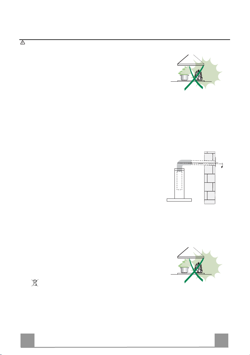
RECOMMENDATIONS AND SUGGESTIONS
The Instructions for Use apply to several versions of this appliance. Accordingly, you may find
descriptions of individual features that do not apply to you r specific appliance.
INSTALLATION
• The manufacturer will not be held liable for any damages resulting from incorrect or improper
installation.
• The minimum safety distance between the cooker top and the extractor hood is 650 mm (some
models can be installed at a lower height, please refer to the paragraphs on working dimensions
and installation).
• Check that the mains voltage corresponds to that indicated on the rating plate fixed to the inside of
the hood.
• For Class I appliances, check that the domestic po wer supply guarantees adequate earthing.
Connect the extractor to the exhaust flue through a pipe of minimum diameter 120 mm. The route
of the flue must be as short as possible.
• Do not connect the extractor hood to exhaust ducts carrying combustion fumes (boilers, fireplaces,
etc.).
• If the extractor is used in conjunction with non-electrical appliances (e.g. gas burning appliances), a
sufficient degree of aeration must be guaranteed in the room in order to prevent the backflow of
exhaust gas. The kitchen must have an opening communicating directly with the open air in order
to guarantee the entry of clean air. When the cooker hood is used in conjunction with appliances
supplied with energy other than electric, the negative pressure in the room must not exceed 0,04
mbar to prevent fumes being drawn back into the room b y the cooker hood.
• In the event of damage to the power cable, it must be replaced by the manufacturer or by the
technical service department, in order to prevent an y risks.
• If the instructions for installation for the gas hob specify a greater distance specified above, this has
to be taken into account. Regulations concerning the discharge of air have to be fulfilled.
USE
• The extractor hood has been designed ex clusively for domestic use to eliminate kitchen smells.
• Never use the hood for purposes other than for wh ich it has been designed.
• Never leave high naked flames under the hood wh en it is in operation.
• Adjust the flame intensity to direct it onto the bottom of the pan only, making sure that it does not
engulf the sides.
• Deep fat fryers must be continuously monitor ed during use: overheated oil can burst into flames.
• Do not flambè under the range hood; risk of fire
• This appliance is not intended for use by persons (including children) with reduced physical, sensory or mental capabilities, or lack of experience and knowledge, unless they have been given supervision or instruction concerning use of the appli ance by a person responsible for their safety.
• Children should be supervised to ensure that they d o not play with the appliance.
• “ CAUTION: Accessible parts may become hot when use d with cooking appliances.”.
MAINTENANCE
• Switch off or unplug the appliance from the mains supply before carrying out any maintenance
work.
• Clean and/or replace the Filters after the specified ti me period (Fire hazard).
• Clean the hood using a damp cloth and a neutral liq uid detergent.
The symbol on the product or on its packaging indicates that thi s product may not be treated as household waste. Instead it shall be handed over to the
applicable collection point for the recy cling of electrical and electronic equipment . By ensuring this product is disposed of corre ctly, you will help prevent potential neg ative
consequences for the environment and h uman health, which could otherwise be cau sed by inappropriate waste handling of this product. For more detailed information
about recycling of this product, p lease contact your local city o ffice, your household waste disp osal service or the shop where you purchased the product
.
EN
3
3
Page 4
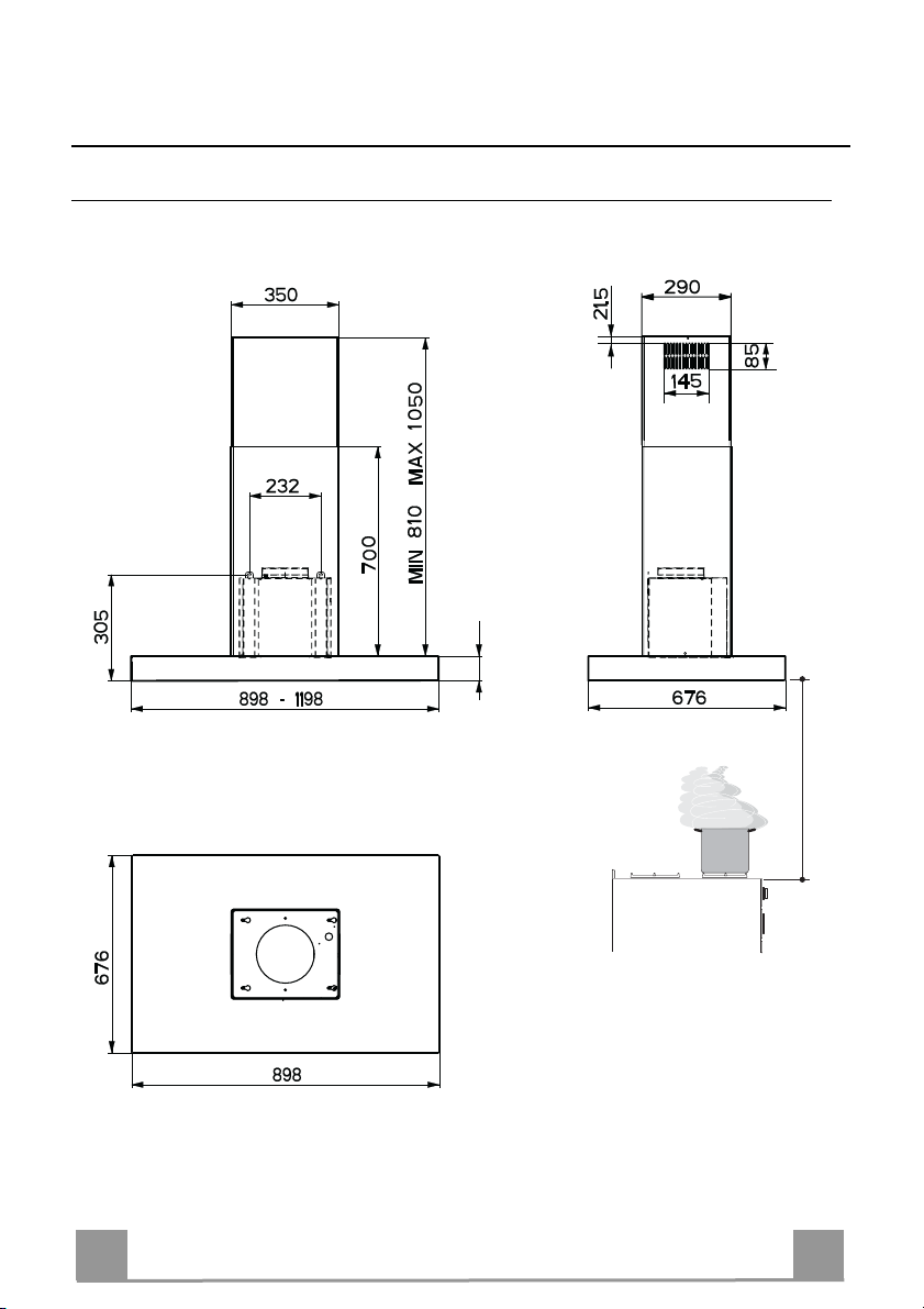
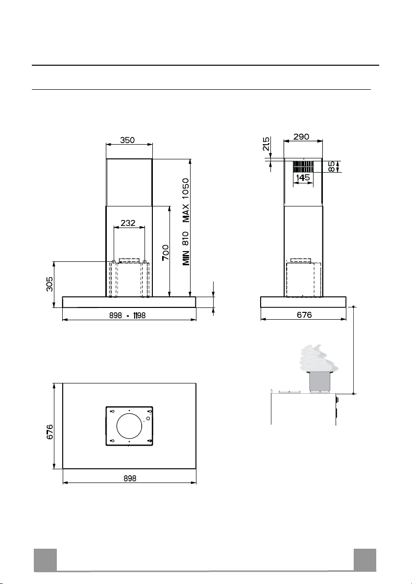
CHARACTERISTICS
Dimensions
45
EN
650 min.
4
4
Page 5
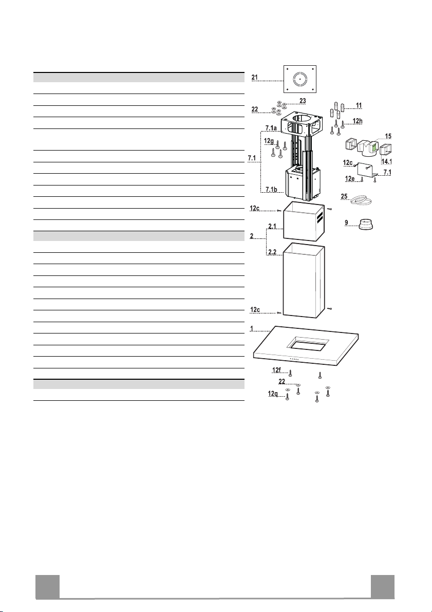
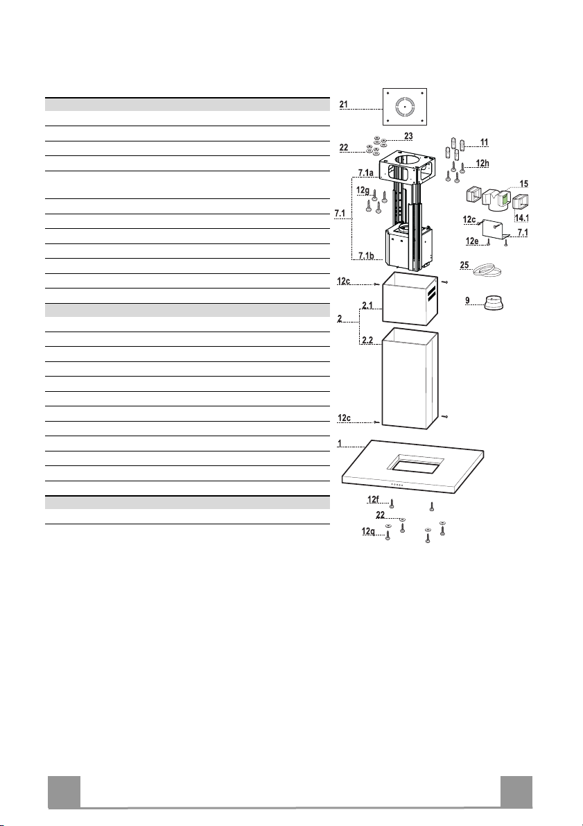
Components
Ref. Q.ty Product Components
1 1 Hood Canopy complete with: Controls, Light, Filters
2 1 Telescopic chimney, made up of:
2.1 1 Upper chimney
2.2 1 Lower chimney
7.1 1 Telescopic frame complete with Suction fan, made up
of:
7.1a 1 Upper frame
7.1b 1 Lower frame
9 1 Reduction flange ø 150-120 mm
14.1 2 Air Outlet Connector Extension
15 1 Air Outlet Connector
25 Hose clamps (not supplied)
Ref. Q.ty Installation Components
7.3 1 Air Outlet Connector fixing bracket
11 4 Wall plugs ø 10
12c 6 Screws 2.9 x 6.5
12e 2 Screws 2.9 x 9.5
12f 2 Screws M4 x 80
12g 4 Screws M6 x 80
12h 4 Screws 5.2 x 70
12q 4 Screws 3.5 x 9.5
21 1 Drilling template
22 8 Washers ø 6.4
23 4 Nuts M6
Q.ty Documentation
1 Instruction Manual
EN
5
5
Page 6
INSTALLATION
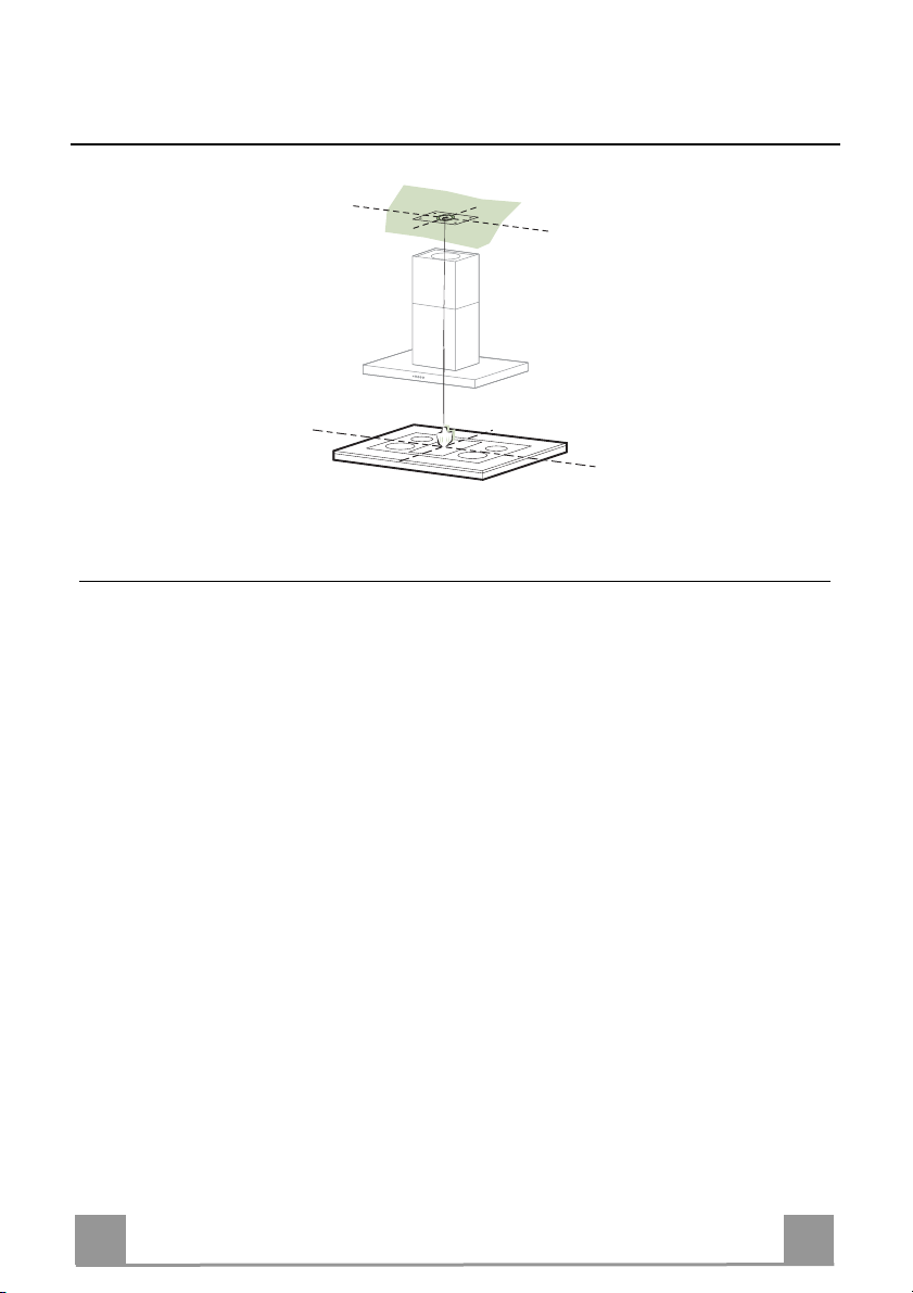
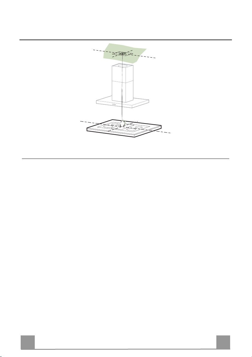
Drilling the Ceiling/shelf and fixing the frame
DRILLING THE CEILING/SHELF
• Use a plumb line to mark the centre of the hob on the ceiling/support shelf.
• Place the drilling template 21 provided on the ceiling/support shelf, making sure that the
template is in the correct position by lining up the axes of the template with those of the hob.
• Mark the centres of the holes in the template.
• Drill the holes at the points marked:
• For concrete ceilings, drill for plugs appropriate to the screw size.
• For hollow brick ceilings with wall thickness of 20 mm: drill ø 10 mm(immediately insert
the Dowels 11 supplied).
• For wooden beam ceilings, drill according to the wood screws used.
• For wooden shelf, drill ø 7 mm.
• For the power supply cable feed, drill ø 10 mm.
• For the air outlet (Ducted Version), drill according to the diameter of the external air exhaust duct connection.
• Insert two screws of the following type, crossing them and leaving 4-5 mm from the ceiling:
• For concrete ceilings, use the appropriate plugs for the screw size (not provided).
• for Cavity ceiling with inner space, with wall thickness of approx. 20 mm, Screws 12h,
supplied.
• For wooden beam ceilings, use 4 wood screws (not provided).
• For wooden shelf, use 4 screws 12g with washers 22 and nuts 23, provided.
EN
6
6
Page 7
2
2
1
1
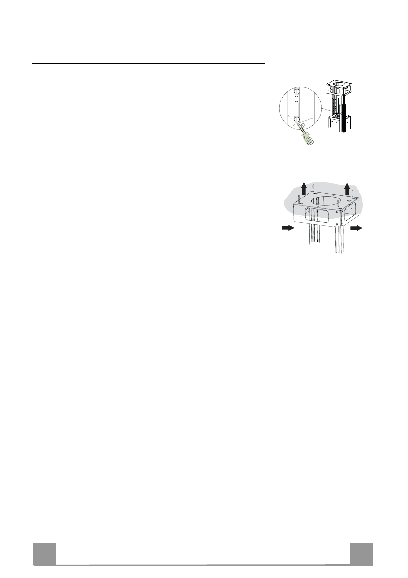
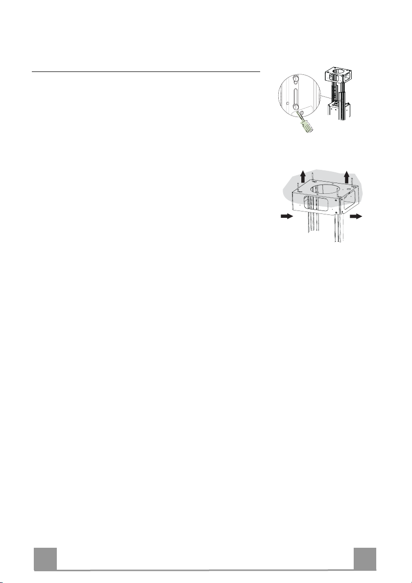
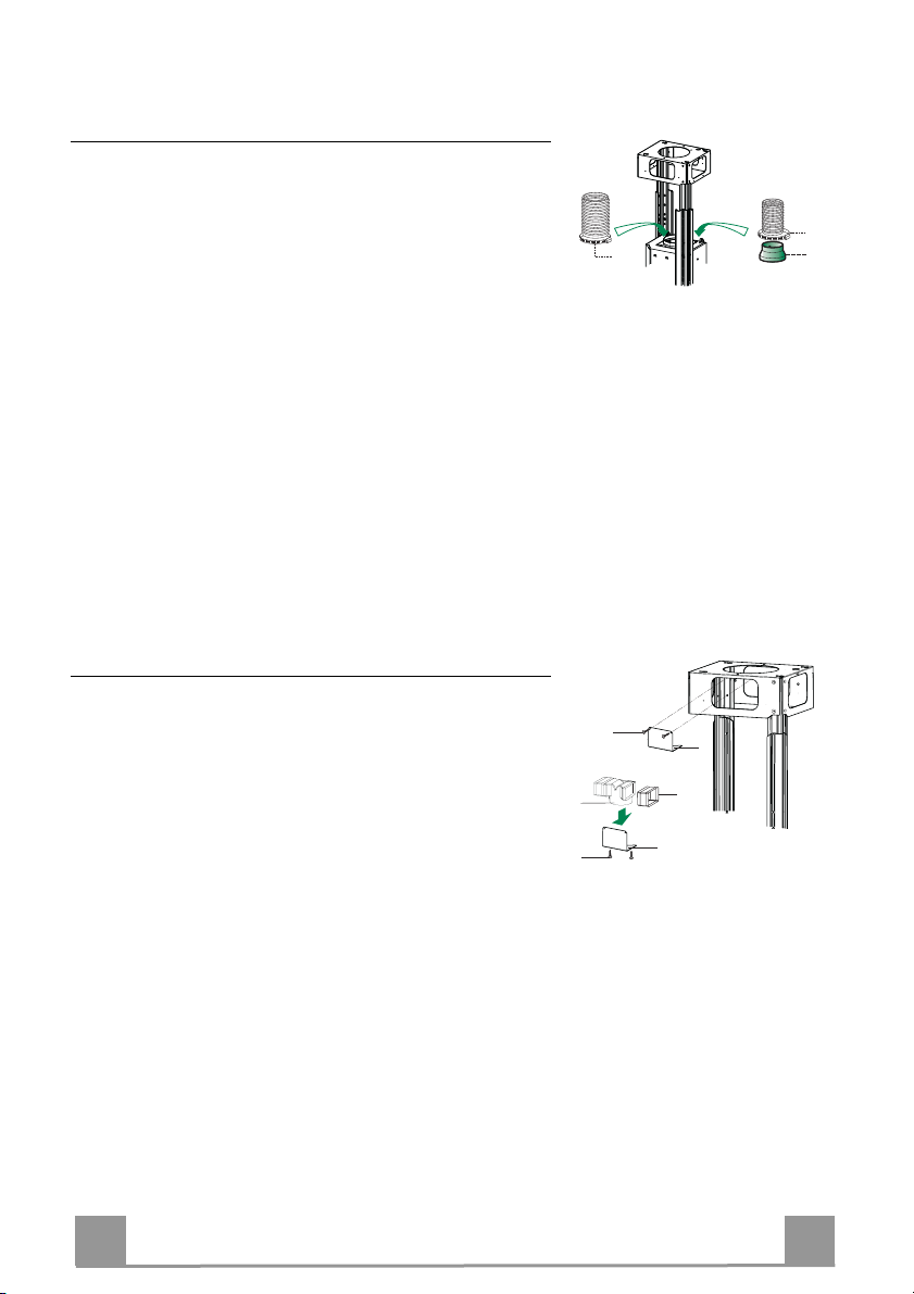
Fixing the frame
• Loosen the two screws fastening the lower chimney and remove this from the lower frame.
• Loosen the two screws fastening the upper chimney and remove this from the upper frame.
If you wish to adjust the height of the frame, proceed as follows:
• Unfasten the metric screws joining the two columns, located at
the sides of the frame.
• Adjust the frame to the height required, then refit all the screws
removed as above.
• Insert the upper chimney stack from above, and leave it running free on the frame.
• Lift up the frame, fit the frame slots onto the screws up to the
slot end positions.
• Tighten the two screws and fasten the other two screws provided with the hood.
Before tightening the screws completely it is possible to adjust
the frame by turning it. Make sure that the screws do not come
out of their seats in the slotted holes.
• The frame mountings must be secure to withstand the weight
of the hood and any stresses caused by the occasional side
thrust applied to the device.
On completion, check that the base is stable, even if the frame
is subjected to bending.
• In all cases where the ceiling is not strong enough at the suspension point, the installer must provide strengthening using
suitable plates and backing pieces anchored to the structurally
sound parts.
EN
7
7
Page 8
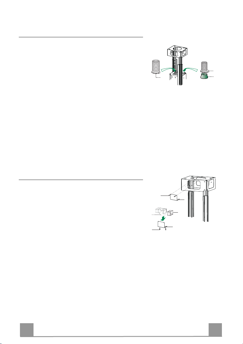
Connections
DUCTED VERSION AIR EXHAUST SYSTEM
When installing the ducted version, connect the hood to
the chimney using either a flexible or rigid pipe ø 150 or
120 mm, the choice of which is left to the installer.
• To install a ø 120 mm air exhaust connection, insert the
reducer flange 9 on the hood body outlet.
• Fix the pipe in position using sufficient pipe clamps
(not supplied).
• Remove any activated charcoal filters.
Air outlet – Recirculation Version
• Insert the Connector extensions 14.1 into the side of the
Connector 15.
• Insert the Connector 15 into the Support bracket 7.3 and
fix it with the screws.
• Fasten the Support bracket 7.3, fixing it to the upper
part with the Screws.
• Make sure that the Connector extensions outlet 14.1 is
in correspondence with the Chimney openings both
horizontally and vertically.
• Join the Connector 15 to the Hood canopy outlet using a
rigid or flexible pipe ø¸150 mm, selection of which is at
the discretion of the installation technician.
• Make sure that the Activated charcoal odour filter has
been fitted.
ø 150
15
12e
ø 120
25
25
9
12c
7.3
14.1
7.3
EN
8
8
Page 9
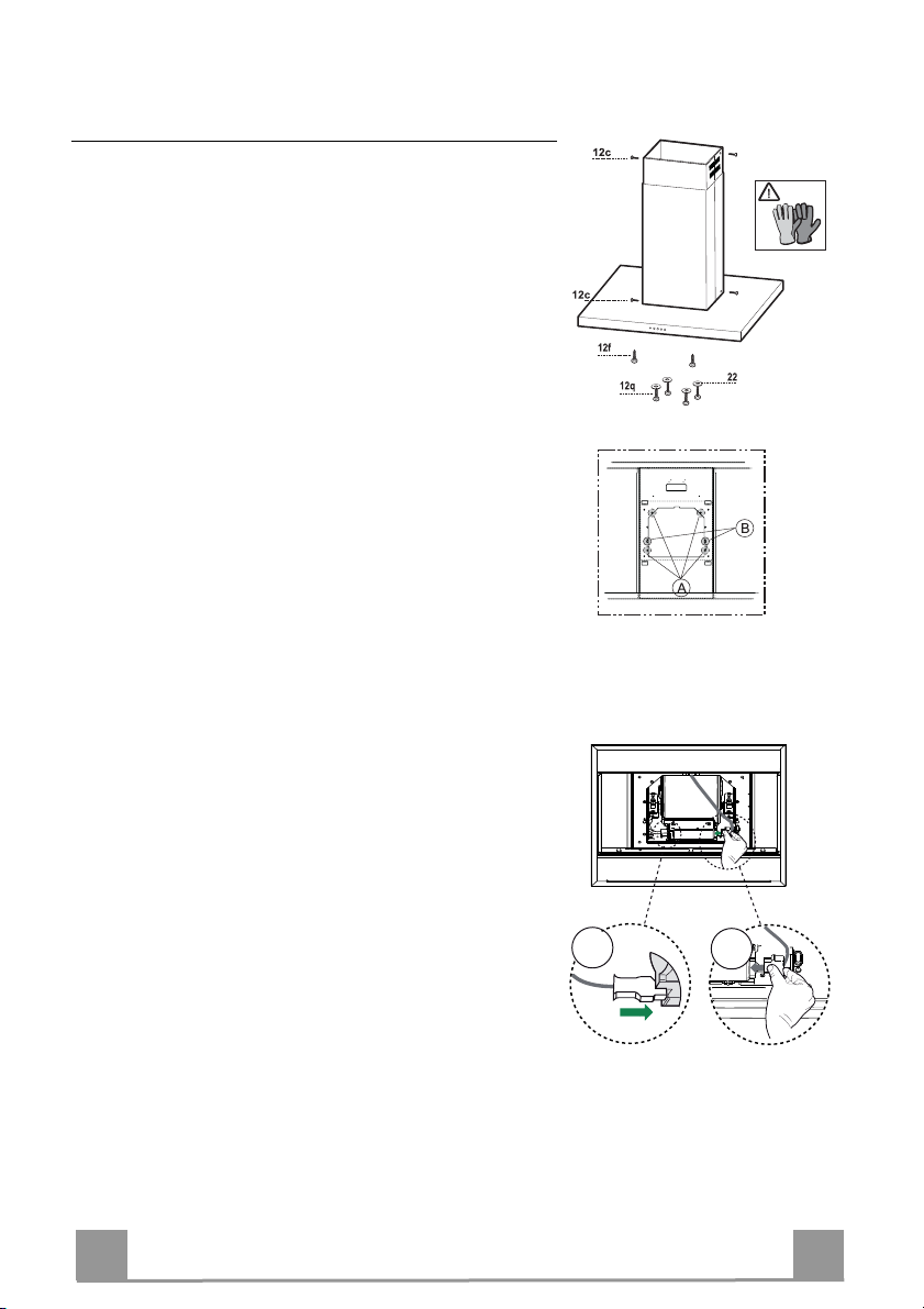
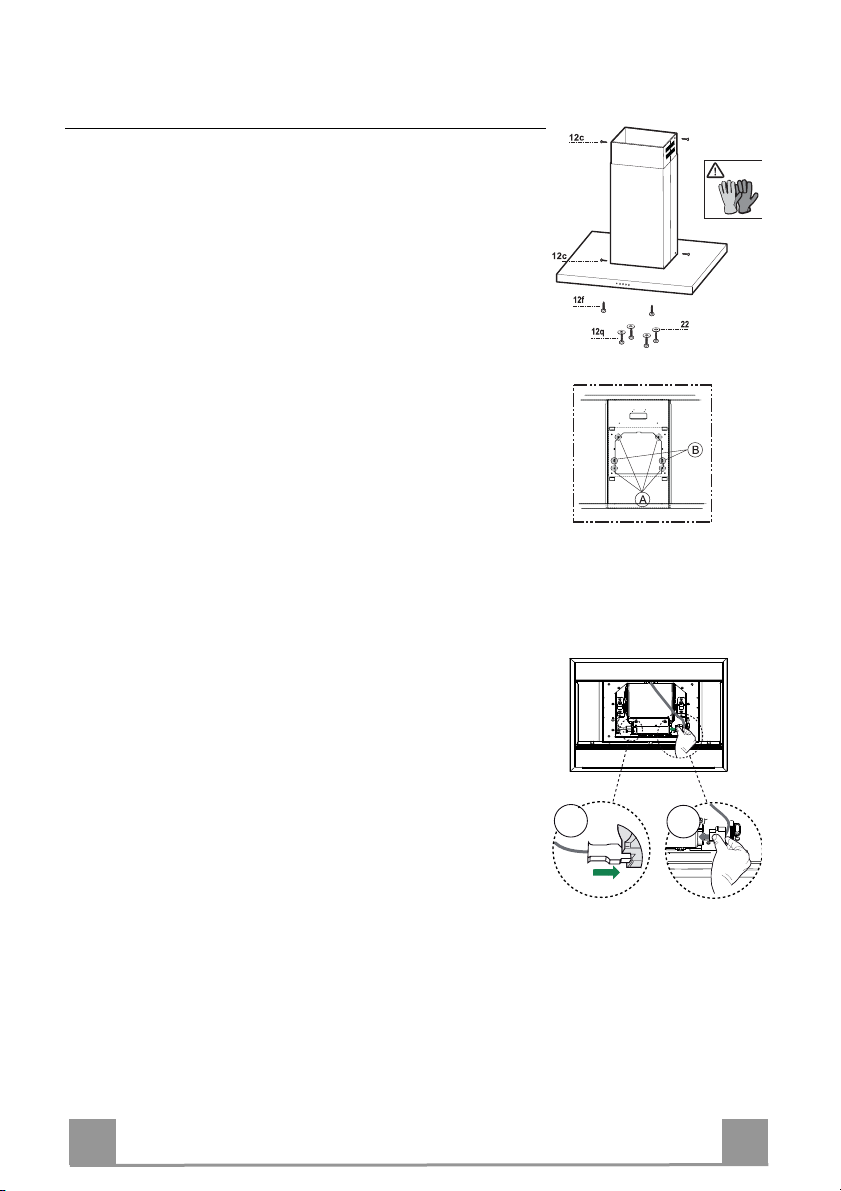
Flue assembly - Mounting the hood body
• Position the upper chimney section and fix the upper part
to the frame using the 2 screws 12c (2,9 x 6,5) provided.
• Similarly, position the lower chimney section and fix the
lower part to the frame using the 2 screws 12c (2,9 x 6,5)
provided.
Before fixing the hood canopy to the frame:
• Screw the 2 screws 12f half way into the holes provided
in the sides of the bottom of the frame.
• Remove the grease filters from the hood canopy.
• Remove any activated charcoal filters.
• Lift the hood canopy and engage the screws 12f in the
slots (A) as far as they will go.
• Working from below, fix the hood canopy to the frame
(B), using the 4 screws 12q and 4 washers 22 provided,
then tighten all the screws securely.
ELECTRICAL CONNECTION
• Connect the Hood to the Mains Power Supply, inserting a
bipolar switch with a contact aperture of at least 3 mm.
• Remove the Grease filters (see paragraph “Maintenance”)
and make sure that the Power cable (A) has been properly
inserted into the Suction fan socket.
• Fasten the connector B to the free socket at the side of the
suction fan
EN
A
B
9
9
Page 10
USE
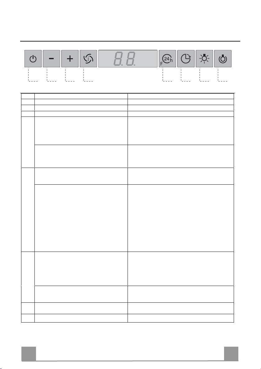
A B C D E F G H
Control panel
Button Function Display
A Turns the suction motor on and off at speed one. Displays the set speed
B Decreases the working speed. Displays the set speed
C Increases the working speed. Displays the set speed
D Activate intensive speed from any other speed,
including motor off. This speed is set to operate
for 10 minutes, after which the system returns to
the speed that was set before. Suitable to deal with
maximum levels of cooking fumes.
Press and hold the button for approximately 5
seconds, with all the loads turned off (Motor and
Lights), to turn the Activated Charcoal Filter
alarm On and Off.
E 24H function
Turns the suction motor on at speed one and
effects one 10 minute extraction every hour.
When the filters alarm is triggered, the alarm can
be reset by pressing and holding this button for
approximately 3 seconds.
These indications are only visible when the motor
is turned off.
F Delay function
Activate automatic switch-off with a 30’ delay.
Suitable to complete elimination of residual
odours. Can be activated from any position, and is
disabled by pressing the button or turning the
motor off.
Press and hold the button for approximately 5
seconds, with all the loads turned off (Motor and
Lights), to turn the Remote Control On and Off.
G Turns the lighting system on and off at maximum
intensity.
H Turns the Courtesy Lighting on and off.
EN
Displays HI and the time remaining once very second.
FC+Punto (2 flashes)–Alarm On.
FC+Punto (1 flash)–Alarm Off.
Displays 24 and the spot at the bottom right flashes once
every second, while the motor is running.
It is disabled by pressing the button.
FF flashes three times.
When the procedure terminates, the indication shown
previously turns off:
FG indicates the need to wash the metal grease filters.
The alarm is triggered after the Hood has been in
operation for 100 working hours.
FC indicates the need to change the activated charcoal
filters, and also to wash the metal grease filters. The alarm
is triggered after the Hood has been in operation for 200
working hours.
Displays the operating speed and the spot at the bottom
right flashes once a second.
IR+Punto (2 flashes)–Alarm On.
IR+Punto (1 flash)–Alarm Off.
1
10
Page 11
MAINTENANCE
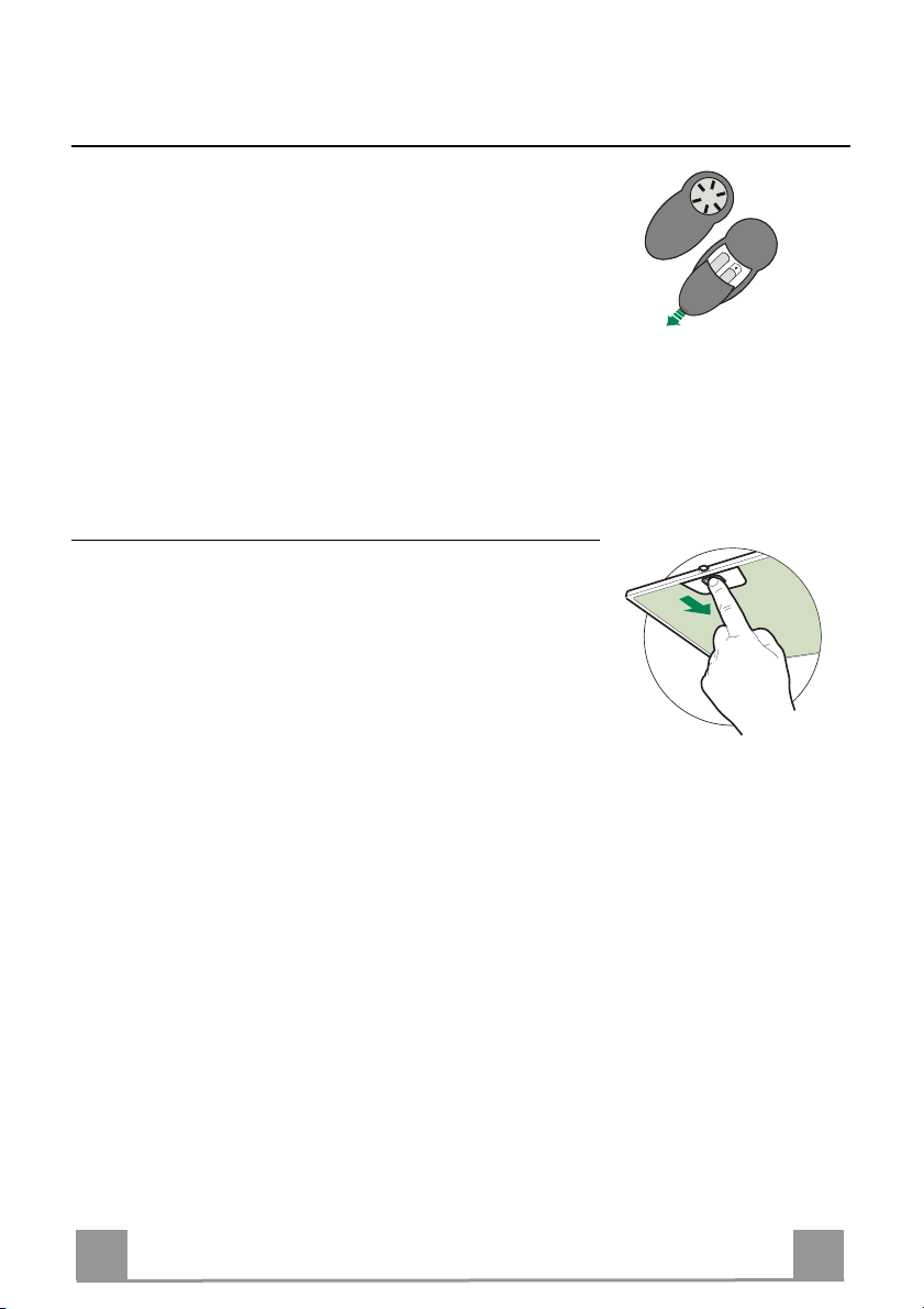
REMOTE CONTROL (OPTIONAL)
The appliance can be controlled using a remote control powered
by a 1.5 V carbon-zinc alkaline batteries of the standard LR03AAA type (not included).
• Do not place the remote control near to heat sources.
• Used batteries must be disposed of in the proper manner.
Metal grease filters
They can be washed in the dishwasher, and need to be cleaned
whenever the FG sign appears on the display or at least once
every 2 months use, or more frequently if use is particularly
intensive.
Resetting the alarm signal
• Turn the Lights and the Suction motor off, then disable the 24h
function, if enabled.
• Press button E (see the paragraph on Use).
Cleaning the Filters
• Remove the Filters one at a time, pushing them towards the
back of the unit and at the same time pulling downward.
• Wash the Filters without bending them, and leave them to dry
completely before replacing. (If the surface of the filter
changes colour as time goes by, this will have absolutely no
effect on the efficiency of the filter itself.)
• Replace, taking care to ensure that the handle faces forwards.
EN
1
11
Page 12
Activated Charcoal Filter (Recirculation Version)
It cannot be washed or regenerated, and must be changed when the FC symbol on the display
appears, or at least once every 4 months. The Alarm signal, if it has been activated, only
appears when the Suction motor is turned on.
Activating the alarm signal
• In Recirculation Version Hoods, the Filter Saturation Alarm must be activated on
installation or at a later date.
• Turn the Lights and the Suction Motor off.
• Press D and hold for approximately 5 Seconds:
• The message FC+Puntino flashes twice, A.C. Filter saturation alarm ACTIVATED
• The message FC+Puntino flashes once, A.C. Filter saturation alarm DEACTIVATED
CHANGING THE ACTIVATED CHARCOAL FILTER
Resetting the alarm signal
• Turn the Lights and the Suction motor off, then disable the
24h function, if enabled.
• Press button E (see the paragraph on Use).
Changing the Filter
• Remove the Metal grease filters.
• Remove the saturated charcoal filter by releasing the fixing
hooks.
• Fit the new filter and fasten it in its correct position.
• Replace the Metal grease filters.
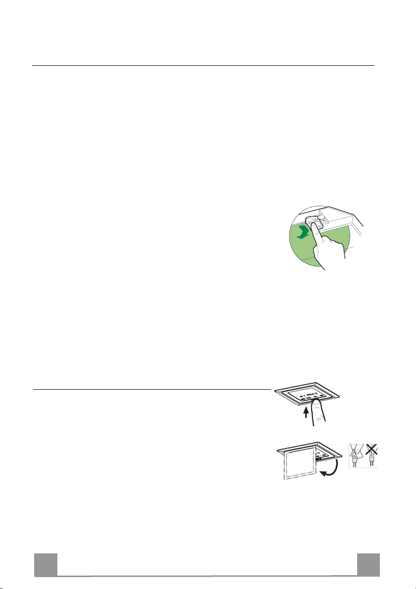
Lighting
CHANGING LAMPS
Halogen lamps
• Open the spotlight cover.
• Remove the halogen lamp from the lamp holder.
• Replace it with another lamp that has the same characteristics,
making sure that the two pins are inserted properly into the
housings in the lamp holder.
• Close the spotlight cover.
EN
1
12
Page 13

2°
CONSIGLI E SUGGERIMENTI
Questo libretto di istruzioni per l'uso è previsto per più versioni dell' apparecchio. É possibile che siano
descritti singoli particolari della dotazione, che non riguardano il Vostro a pparecchio.
INSTALLAZIONE
• Il produttore declina qualsiasi responsabilità per danni dovuti ad installazione non corretta o non conforme
alle regole dell’arte.
• La distanza minima di sicurezza tra il Piano di cottura e la Cappa deve essere di 650 mm, (alcuni modelli
possono essere installati ad un’altezza inf eriore, fare riferimento ai paragrafi ingombro e installazione).
• Verificare ch e la tensione di rete corrisponda a quella riportata nel la targhetta posta all’interno della Cappa.
• Per Apparecchi in Classe I
terra.
• Collegare la Cappa all’uscita dell’aria aspirata con tubazione di diametro pari o superiore a 120 mm. Il
percorso della tubazione de ve essere il più breve possibile.
• Non collegar e la Cappa a condotti di scarico dei fumi prodotti da c ombustione (caldaie, caminetti, ecc.).
• Nel caso in c ui nella stanza vengano utilizzati sia la C appa che apparecchi non azionati da ener gia elettrica
(ad esempio apparecchi utilizzatori di gas), si deve provvedere ad una aerazione sufficiente dell’ambiente.
Se la cucina ne fosse sprovvista, praticare un’apertura che comunichi con l’esterno, per garantire il richiamo d’aria pulita. Un uso proprio e senza rischi si ottiene quando la depressione massima del locale non
supera i 0,04 mBar.
• In caso di danneggiamento del cavo alimentazione, esso deve essere sostituito dal costr uttore o dal servizio di assistenza tecnica, in modo da prevenire ogni ris chio.
• Se le istruzioni di installazione del dispositivo di cottura a gas indicano che è necessaria una distanza
maggiore di quella indicato sopr a, è necessario tenerne conto. Bisogna rispettare tutte le normative relative
allo scarico dell’aria.
USO
• La Cappa è stata progettata esclusivamente per uso domestico, per abbattere gli odori della cucina.
• Non fare mai us o improprio della Cappa.
• Non lasciare f iamme libere a forte intensità sotto la Cappa in funz ione.
• Regolare sempre le fiamme in modo da evitare una evidente fuoriuscita laterale delle stesse rispetto al
fondo delle pentole.
• Controllar e le friggitrici durante l’uso: l’olio surriscaldat o potrebbe infiammarsi.
• Non preparar e alimenti flambè sotto la cappa da cucina; peric olo d'incendio.
• Questo appar ecchio non deve essere utilizzato da persone (bambini inc lusi) con ridotte capacità psichiche,
sensoriali o mentali, oppu re da persone senza esperienza e conoscenza, a meno c he non siano controllati
o istruiti all’uso dell’appa recchio da persone responsabili della loro sicurezz a.
• I bambini dev ono essere supervisionati per assicurarsi che non gioc hino con l’apparecchio.
• “ATTENZIONE: Le parti accessibili possono diventare molto calde se utilizzate con degli apparecchi di
cottura”.
MANUTENZIONE
• Prima di procedere a qualsiasi operazione di manutenzione, disinserire la Cappa togliendo la spina elettrica o spegnendo l’interruttore ge nerale.
• Effettuare una scrupolosa e tempestiva manutenzione dei Filtri secondo gli intervalli consigliati (Rischio di
incendio).
• Per la pulizia delle superfici della Cappa è sufficiente utili zzare un panno umido e detersivo liquido neutro.
a
accertarsi che l’impianto elettrico domestico garantisca un corretto scarico a
Il simbolo sul prodotto o sulla confezione indica che il prodotto non deve essere considerato come un normale
rifiuto domestico, ma deve essere portato nel punto di raccolta appropriato per il riciclaggio di apparecchiature elettriche
ed elettroniche. Provvedendo a smaltire questo prodotto in modo appropriato, si contribuisce a evitare potenziali conseguenze negative per l’ambiente e per la salute, che potrebbero derivare da uno smaltimento inadeguato del prodotto.
Per informazioni più dettagliate sul riciclaggio di questo prodotto, contattare l’ufficio comunale, il servizio locale di smaltimento rifiuti o il ne gozio in cui è stato acquistat o il prodotto.
IT
1
13
Page 14
CARATTERISTICHE
Ingombro
45
IT
650 min.
1
14
Page 15
Componenti
Rif. Q.tà Componenti di Prodotto
1 1 Corpo Cappa completo di: Comandi, Luce, Filtri
2 1 Camino telescopico formato da:
2.1 1 Camino superiore
2.2 1 Camino inferiore
7.1 1 Traliccio telescopico completo di Aspiratore, formato
da:
7.1a 1 Traliccio superiore
7.1b 1 Traliccio inferiore
9 1 Flangia di riduzione ø 150-120 mm
14.1 2 Prolunga Raccordo Uscita Aria
15 1 Raccordo Uscita Aria
25 Fascette stringitubo (non incluse)
Rif. Q.tà Componenti di Installazione
7.3 1 Staffa fissaggio Raccordo Uscita Aria
11 4 Tasselli ø 10
12c 6 Viti 2,9 x 6,5
12e 2 Viti 2,9 x 9,5
12f 2 Viti M4 x 80
12g 4 Viti M6 x 80
12h 4 Viti 5,2 x 70
12q 4 Viti 3,5 x 9,5
21 1 Dima di foratura
22 8 Rondelle ø 6,4
23 4 Dadi M6
Q.tà Documentazione
1 Libretto Istruzioni
IT
1
15
Page 16
INSTALLAZIONE
Foratura Soffitto/Mensola e Fissaggio Traliccio
FORATURA SOFFITTO/MENSOLA
• Con l’ausilio di un Filo a piombo riportare sul Soffitto/Mensola di supporto il centro del
Piano di Cottura.
• Appoggiare al Soffitto/Mensola la Dima di Foratura 21 in dotazione, facendo coincidere il
suo centro al centro proiettato e allineando gli assi della Dima agli assi del Piano di Cottura.
• Segnare i centri dei Fori della Dima.
• Forare i punti seguenti:
• Soffitto in Calcestruzzo massiccio: secondo Tasselli per Calcestruzzo impiegati.
• Soffitto in Laterizio a camera d’aria, con spessore resistente di 20 mm: ø 10 mm (inserire
subito i Tasselli 11 in dotazione).
• Soffitto in Travatura di Legno: secondo Viti per Legno impiegate.
• Mensola in Legno: ø 7 mm.
• Passaggio del Cavo elettrico di Alimentazione: ø 10 mm.
• Uscita Aria (Versione Aspirante): secondo diametro del collegamento alla Tubazione di
Evacuazione Esterna.
• Avvitare, incrociandole e lasciando 4-5 mm dal soffitto, due viti:
• per Calcestruzzo massiccio, Tasselli per Calcestruzzo, non in dotazione.
• per Laterizio a camera d’aria, con spessore resistente di 20 mm circa, Viti 12h, in dotazio-
ne.
• per Travatura di legno, Viti per legno, non in dotazione.
• per Mensola in Legno, viti 12g con Rondelle 22 e Dadi 23, in dotazione.
IT
1
16
Page 17
Fissaggio Traliccio
• Svitare le due viti che fissano il camino inferiore e sfilarlo
dal traliccio (dalla parte inferiore).
• Svitare le due viti che fissano il camino superiore e sfilarlo
dal traliccio (dalla parte superiore).
Nel caso in cui si voglia regolare l’altezza del traliccio procedere come segue:
• Svitare le viti metriche che uniscono le due colonne, poste ai
lati del traliccio;
• Regolare l’altezza desiderata del traliccio e riavvitare le viti
precedentemente tolte;
• Inserire il camino superiore dall’ alto e lasciarlo libero sul
traliccio;
• Sollevare il traliccio, incastrare le asole sulle viti e scorrere
fino a battuta;
• Stringere le due viti e avvitare le altre due in dotazione;
Prima di serrare definitivamente le viti è possibile effettuare
delle regolazioni spostando il traliccio, facendo attenzione che
le viti non escano dalla sede dell’asola di regolazione.
• Il fissaggio del Traliccio deve essere sicuro in relazione sia
al peso della Cappa sia alle sollecitazioni causate da occasionali spinte laterali all’Apparecchio montato. A fissaggio avvenuto verificare quindi che la base sia stabile anche se il
Traliccio è sollecitato a flessione.
• In tutti i casi in cui il Soffitto non fosse sufficientemente robusto sul punto di sospensione, l’Installatore dovrà provvedere a irrobustirlo con opportune piastre e contropiastre ancorate a parti strutturalmente resistenti.
1
2
1
2
IT
1
17
Page 18
Connessioni
USCITA ARIA VERSIONE ASPIRANTE
Per installazione in Versione Aspirante collegare la Cappa
alla tubazione di uscita per mezzo di un tubo rigido o flessibile di ø150 o 120 mm, la cui scelta è lasciata all'installatore.
• Per collegamento con tubo ø120 mm, inserire la Flangia
di riduzione 9 sull’Uscita del Corpo Cappa.
• Fissare il tubo con adeguate fascette stringitubo. Il materiale occorrente non è in dotazione.
• Togliere eventuali Filtri Antiodore al Carbone attivo.
Uscita aria Versione Filtrante
• Inserire lateralmente le Prolunghe Raccordo 14.1 sul
Raccordo 15.
• Inserire il Raccordo 15 nella Staffa di Sostegno 7.3 fis-
sandolo con le Viti.
• Fissare la Staffa di Sostegno 7.3 fissandola con le Viti
alla parte superiore.
• Assicurarsi che l’uscita delle Prolunghe Raccordo 14.1
risulti in corrispondenza delle bocchette del Camino sia
in orizzontale che in verticale.
• Collegare il Raccordo 15 all’Uscita del Corpo Cappa per
mezzo di un tubo rigido o flessibile di ø150 mm, la cui
scelta è lasciata all'installatore.
• Assicurarsi della presenza del Filtro Antiodore al Carbone attivo.
ø 150
15
12e
ø 120
25
25
9
12c
7.3
14.1
7.3
IT
1
18
Page 19
A
B
Montaggio Camino e Fissaggio Corpo Cappa
• Posizionare il Camino superiore e fissare nella parte superiore
al Traliccio con 2 Viti 12c (2,9 x 6,5) in dotazione.
• Analogamente posizionare il Camino inferiore e fissare nella
parte inferiore al Traliccio con 2 Viti 12c (2,9 x 6,5) in dotazione.
Prima di fissare il Corpo Cappa al Traliccio:
• Avvitare per metà le 2 Viti 12f sulla parte inferiore del traliccio
in posizione laterale in corrispondenza dei 2 fori predisposti.
• Togliere i Filtri antigrasso dal Corpo Cappa;
• Togliere eventuali Filtri Antiodore al Carbone attivo.
• Sollevare il Corpo Cappa e incastrare le Viti 12f sulle asole
(rif.A) fino a battuta.
• Fissare da sotto con 4 Viti 12q e 4 Rondelle 22 in dotazione il
Corpo Cappa al Traliccio predisposto (rif.B) e serrare definitivamente tutte le Viti.
CONNESSIONE ELETTRICA
• Collegare la Cappa all’Alimentazione di Rete interponendo un
Interruttore bipolare con apertura dei contatti di almeno 3 mm.
• Rimuovere i Filtri antigrasso (vedi par. “Manutenzione”) e assicurarsi che il connettore del Cavo di alimentazione (A) sia
correttamente inserito nella presa dell’Aspiratore.
• Collegare il connettore B sulla presa rimasta libera a lato
dell’aspiratore
IT
1
19
Page 20

USO
A B C D E F G H
Quadro comandi
Tasto Funzione Display
A Accende e spegne il motore di aspirazione alla prima
velocità.
B Decrementa la velocità di esercizio. Visualizza la velocità impostata
C Incrementa la velocità di esercizio. Visualizza la velocità impostata
D Attiva la velocità Intensiva da qualsiasi velocità
anche da motore spento, tale velocità è temporizzata a
10 minuti, al termine del tempo il sistema ritorna alla
velocità precedentemente impostata. Adatta a fronteggiare le massime emissioni di fumi di cottura.
Tenendo il tasto premuto per circa 5 secondi, quando
tutti i carichi sono spenti (Motore+Luce), si Attiva /
Disattiva l’allarme dei Filtri al Carbone attivo.
E Funzione 24H
Attiva il motore alla prima velocità e consente
un’aspirazione di 10 minuti ogni ora.
Con l’allarme filtri in corso premendo il tasto per
circa 3 secondi si effettua il reset dell’allarme.
Tali segnalazioni sono visibili solo a motore spento.
F Funzione Delay
Attiva lo spegnimento automatico ritardato di 30’.
Adatto per completare l’eliminazione di odori residui.
Attivabile da qualsiasi posizione, si disattiva premendo il tasto o spegnendo il motore.
Tenendo il tasto premuto per circa 5 secondi, quando
tutti i carichi sono spenti (Motore+Luce), si Attiva /
Disattiva il Telecomando.
G Accende e spegne l’impianto di illuminazione alla
massima intensità.
H Accende e spegne l’impianto di illuminazione in
modalità Luce di Cortesia.
Visualizza la velocità impostata
Visualizza alternamente HI e il tempo rimanente una
volta al secondo.
FC+Punto (2Lampeggi)–Allarme Attivo.
FC+Punto (1Lampeggio)–Allarme Disattivo.
Visualizza 24 e il punto in basso a destra lampeggia una
volta al secondo, mentre il motore è in funzione.
Si disabilita premendo il tasto.
Lampeggia FF tre volte.
Terminata la procedura si spegne la segnalazione precedentemente visualizzata:
FG segnala la necessità di lavare i filtri antigrasso metallici. L’allarme entra in funzione dopo 100 ore di lavoro
effettivo della Cappa.
FC segnala la necessità di sostituire i filtri al carbone
attivo e devono anche essere lavati i filtri antigrasso metallici. L’allarme entra in funzione dopo 200 ore di lavoro
effettivo della Cappa.
Visualizza la velocità di esercizio e il punto in basso a
destra lampeggia una volta al secondo.
IR+Punto (2Lampeggi)–Allarme Attivo.
IR+Punto (1Lampeggio)–Allarme Disattivo.
IT
2
20
Page 21

MANUTENZIONE
TELECOMANDO (OPZIONALE)
Questo apparecchio può essere comandato per mezzo di un telecomando, alimentato con pile alcaline zinco-carbone da 1,5 V del
tipo standard LR03-AAA (non incluse).
• Non riporre il telecomando in prossimità di fonti di calore.
• Non disperdere le pile nell’ambiente, depositarle negli appositi
contenitori.
Filtri antigrasso metallici
Sono lavabili anche in lavastoviglie, e necessitano di essere lavati
quando sul display appare FG o almeno ogni 2 mesi circa di utilizzo o più frequentemente, per un uso particolarmente intenso.
Reset del segnale di allarme
• Spegnere le Luci e il Motore di aspirazione, quindi qualora
fosse attivata la funzione 24h disattivarla.
• Premere il tasto E (Vedi paragrafo Uso).
Pulizia Filtri
• Togliere i Filtri uno alla volta, spingendoli verso la parte posteriore del gruppo e tirando contemporaneamente verso il basso.
• Lavare i Filtri evitando di piegarli, e lasciarli asciugare prima
di rimontarli. (Un’eventuale cambiamento del colore della superficie del filtro, che potrebbe verificarsi nel tempo, non pregiudica assolutamente l’efficienza dello stesso.)
• Rimontarli facendo attenzione a mantenere la maniglia verso la
parte visibile esterna.
IT
2
21
Page 22

Filtri antiodore al Carbone attivo (Versione Filtrante)
Non è lavabile e non è rigenerabile, va sostituito quando sul display appare FC o almeno ogni
4 mesi. La segnalazione di Allarme, se preventivamente attivata, si verifica solo quando è azionato il Motore di aspirazione.
Attivazione del segnale di allarme
• Nelle Cappe in Versione Filtrante, la segnalazione di Allarme saturazione Filtri va attivata al
momento dell’installazione o successivamente.
• Spegnere le Luci e il Motore di aspirazione.
• Premere il tasto D per circa 5 Secondi:
• 2 Lampeggi scritta FC+Puntino -- Allarme saturazione Filtro C.A. ATTIVATO.
• 1 Lampeggio scritta FC+Puntino -- Allarme saturazione Filtro C.A. DISATTIVATO.
SOSTITUZIONE FILTRO ANTIODORE AL CARBONE ATTIVO
Reset del segnale di allarme
• Spegnere le Luci e il Motore di aspirazione, quindi qualora
fosse attivata la funzione 24h disattivarla.
• Premere il tasto E (Vedi paragrafo Uso).
Sostituzione Filtro
• Togliere i Filtri antigrasso metallici.
• Rimuovere il Filtro antiodore al Carbone attivo saturo, agendo sugli appositi agganci.
• Montare il nuovo Filtro agganciandolo nella sua sede.
• Rimontare i Filtri antigrasso metallici.
Illuminazione
SOSTITUZIONE LAMPADE
Lampade alogene
• Aprire il coperchio faretto.
• Estrarre la lampadina alogena dal portalampada.
• Sostituirla con una nuova lampadina di uguali caratteristiche,
facendo attenzione ad inserire correttamente i due spinotti
nella sede del portalampade.
• Chiudere il coperchio faretto.
IT
2
22
Page 23

2°
CONSEILS ET SUGGESTIONS
La présente notice d'emploi vaut pour plusieurs versions de l'appareil. Elle peut contenir des descriptions d'ac-
cessoires ne figurant pas dans votre appareil.
INSTALLATION
• Le fabricant décline toute responsabilité en cas de dommage dû à une installation non correcte ou non
conforme aux règles de l’art.
• La distance minimale de sécurité entre le plan de cuisson et la hotte doit être de 650 mm au moins (certains
modèles peuvent être installés à une hauteur inférieure : se reporter aux paragraphes « Encombrement » et
« Installation »).
• Vérifier que la tension du secteur correspond à la valeur qui figure sur la plaquette apposée à l’intérieur de la
hotte.
• Pour les Appareils appartenant à la Ière Classe, veiller à ce que la mise à la terre de l’installation électrique
domestique ait été effectuée conformément aux normes en vigueur.
• Connecter la hotte à la sortie d’air aspiré à l’aide d’une tuyauterie d’un diamètre égal ou supérieur à 120 mm. Le
parcours de la tuyauterie doit être le plus court possible.
• Ne pas connecter la hotte à des conduites d’évacuation de fumées issues d’une combustion tel que (Chaudière, cheminée, etc…).
• Si vous utilisez des appareils qui ne fonctionnent pas à l’électricité dans la pièce ou est installée la hotte (par
exemple: des appareils fonctionnant au gaz), vous devez prévoir une aération suffisante du milieu. Si la cuisine
en est dépourvue, pratiquez une ouverture qui communique avec l’extérieur pour garantir l’infiltration de l’air pur.
Pour un emploi correct et sans risque, la dépression maximum dans la pièce ne doit pas dépasser 0,04 mbar.
• En cas d’endommagement du cordon d’alimentation, faites-le remplacer par le constructeur ou par le service
après-vente, afin de prévenir tout risque.
• Si les instructions de montage pour la plaque de cuisson au gaz spécifient une plus grande distance indiquée cidessus, cela doit être pris en compte. Règlement concernant l'évacuation d'air doivent être remplies..
UTILISATION
• La hotte a été conçue exclusivement pour l’usage domestique, dans le but d’éliminer les odeurs de la cuisine.
• Ne jamais utiliser abusivement la hotte.
• Ne pas laisser les flammes libres à forte intensité quand la hotte est en service.
• Toujours régler les flammes de manière à éviter toute sortie latérale de ces dernières par rapport au fond des
marmites.
• Contrôler les friteuses lors de l’utilisation car l’huile surchauffée pourrait s’enflammer.
• Ne pas préparer d’aliments flambés sous la hotte de cuisine : risque d’incendie
• Cet appareil ne doit pas être utilisé par des personnes (y compris les enfants) ayant des capacités psychiques,
sensorielles ou mentales réduites, ni par des personnes n’ayant pas l’expérience et la connaissance de ce type
d’appareils, à moins d'être sous le contrôle et la formation de personnes responsables de leur sécurité.
• Les enfants doivent être surveillés pour s'assurer qu'ils ne jouent pas avec l'appareil.
• « ATTENTION : Les parties accessibles peuvent devenir très chaudes si utilisées avec des appareils de cuis-
son. »
ENTRETIEN
• Avant de procéder à toute opération d’entretien, retirer la hotte en retirant la fiche ou en actionnant l’interrupteur
général.
• Effectuer un entretien scrupuleux et en temps dû des Filtres, à la cadence conseillée (Risque d’incendie).
• Pour le nettoyage des surfaces de la hotte, il suffit d’utiliser un chiffon humide et détersif liquide neutre.
Le symbole sur le produit o u son emballage indique que ce produit ne peut êt re traité comme déchet ménager. Il
doit plutôt être remis au point de ramassage concerné, se chargeant du recyclage du matériel électrique et électronique.
En vous assurant que ce produit est éliminé correctement, vous favorisez la prévention des conséquences négatives
pour l’environnement et la santé humaine qui, sinon, seraient le résultat d’un traitement inapproprié des déchets de ce
produit. Pour obtenir plus de détails sur le recyclage de ce produit, veuillez prendre contact avec le bureau municipal de
votre région, votre service d’élimination des déchets ménagers ou le magasin où vous avez acheté le produit.
FR
2
23
Page 24

CARACTERISTIQUES
Encombrement
45
FR
650 min.
2
24
Page 25

Composants
Réf. Q.té Composants de Produit
1 1 Corps Hotte équipé de: Comandes, Lumière, Filtres
2 1 Cheminée Télescopique formée de :
2.1 1 Cheminée Supérieure
2.2 1 Cheminée Inférieure
7.1 1 Treillis télescopique avec Aspirateur, formé par:
7.1a 1 Treillis supérieur
7.1b 1 Treillis inférieur
9 1 Flasque de Réduction ø 150-120 mm
14.1 2 Rallonge Raccord Sortie Air
15 1 Raccord Sortie Air
25 Colliers de serrage serre-tube (non compris)
Réf. Q.té Composants pour l’installation
7.3 1 Bride Support Raccord
11 4 Chevilles ø 10
12c 6 Vis 2,9 x 6,5
12e 2 Vis 2,9 x 9,5
12f 2 Vis M4 x 80
12g 4 Vis M6 x 80
12h 4 Vis 5,2 x 70
12q 4 Vis 3,5 x 9,5
21 1 Gabarit de perçage
22 8 Rondelles øi 6,4
23 4 Écrous M6
Q.té Documentation
1 Manuel d’instructions
FR
2
25
Page 26

INSTALLATION
Perçage Plafond/Étagère et Fixation Treillis
PERÇAGE PLAFOND/ETAGERE
• À l’aide d’un Fil à plomb, reporter sur le Plafond/Étagère de support le centre du Plan de
Cuisson.
• Poser contre le Plafond/Étagère le Gabarit de Perçage 21 fourni avec l’appareil, en faisant
coïncider son centre avec le centre projeté et en alignant les axes du Gabarit avec les axes du
Plan de Cuisson.
• Marquer les centres des Trous du Gabarit.
• Percer les trous qui ont été marqués:
• Plafond en Béton massif: en fonction des Goujons pour Béton utilisés.
• Plafond en Briques avec chambre à air, avec épaisseur résistante de 20 mm: ø 10 mm (in-
sérer immédiatement les Chevilles 11 fournies avec l’appareil).
• Plafond en Poutrage en Bois: en fonction des Vis à Bois utilisées.
• Étagère en Bois: ø 7 mm.
• Passage du Câble électrique d’Alimentation: ø 10 mm.
• Sortie Air (Version Aspirante): en fonction du diamètre de la connexion avec les Tuyaux
d’Évacuation Externe.
• Visser deux vis en les croisant et en laissant 4-5 mm. de distance par rapport au plafond:
• pour le Béton massif, des Goujons pour Béton, non fournis avec l’appareil.
• pour Briques percées, ayant une épaisseur résistante de 20 mm. environ, utiliser les Vis
12h, fournies avec l'appareil.
• pour le Poutrage en bois, 4 Vis à bois, non fournies avec l’appareil.
• pour l’Étagère en Bois, 4 Vis 12g avec Rondelles 22 et Écrous 23, fournis avec l’appareil.
FR
2
26
Page 27

FiXATION TREILLIS
• Dévisser les deux vis qui fixent la cheminée inférieure et sortir cette dernière du treillis (depuis la partie inférieure).
• Dévisser les deux vis qui fixent la cheminée supérieure et
sortir cette dernière du treillis (depuis la partie supérieure).
Si l’on souhaite régler la hauteur du treillis, effectuer les opérations suivantes:
• Dévisser les vis métriques qui unissent les deux colonnes,
qui se trouvent sur les côtés du treillis.
• Régler la hauteur souhaitée du treillis et revisser les vis qui
ont été précédemment retirées.
• Insérer la cheminée supérieure depuis le haut et la laisser
libre sur le treillis.
• Soulever le treillis, encastrer les oeillets sur les vis et faire
coulisser jusqu’à la butée;
• Serrer les deux vis et visser les autres deux vis fournies avec
l’appareil;
Avant de serrer définitivement les vis, il est possible
d’effectuer des réglages, en déplaçant le treillis, tout en contrôlant que les vis ne sortent pas du logement de l’œillet de réglage.
• La fixation du Treillis doit être solide, en fonction du poids
de la Hotte et des contraintes provoquées par les poussées latérales occasionnelles auxquelles l’Appareil monté sera
soumis. Après avoir effectué la fixation, vérifier que la base
soit stable, même si le Treillis est soumis à des contraintes de
flexion.
• Dans tous les cas où le Plafond ne devait pas être suffisamment robuste en correspondance du point d’accrochage,
l’Installateur devra se charger de le rendre plus solide au
moyen de plaques et contre-plaques spéciales, ancrées sur les
parties structuralement résistantes.
1
2
1
2
FR
2
27
Page 28

9
ø 150
ø 120
25
25
Branchements
SORTIE AIR VERSION ASPIRANTE
En cas d’installation en version aspirante, brancher la hotte à la
tuyauterie de sortie via un tube rigide ou flexible de ø 150 ou
120 mm, au choix de l’installateur.
• En cas de branchement avec un tube de ø120 mm, insérer le
flasque de réduction 9 sur la sortie du corps de la hotte.
• Fixer le tube par des colliers appropriés. Le matériau nécessaire n’est pas fourni.
• Retirer les éventuels filtres anti-odeur au charbon actif.
Sortie de l’air version filtrante
• Monter latéralement les rallonges du raccord 14.1 sur le rac-
cord 15 ;
• Placer le raccord 15 dans l’étrier de soutien 7.3 en le fixant
avec les vis ;
• Fixer l’étrier de soutien 7.3 en le fixant avec les vis à la partie supérieure.
• S’assurer que la sortie des rallonges du raccord 14.1 se
trouve en face des ouvertures du conduit, aussi bien horizontalement que verticalement ;
• Raccorder le raccord 15 à la sortie du corps de hotte au
moyen d’un tuyau rigide ou flexible de 150 mm de diamètre,
au choix de l'installateur ;
• S’assurer de la présence du filtre anti-odeur au charbon actif.
FR
12c
15
12e
7.3
14.1
7.3
2
28
Page 29

Montage Cheminée - Montage Corps Hotte
• Positionner la Cheminée supérieure et fixer cette dernière
dans la partie supérieure du Treillis à l’aide de 2 Vis 12c
(2,9 x 6,5) fournies avec l’appareil.
• De la même façon, positionner la Cheminée inférieure et
fixer cette dernière dans la partie inférieure du Treillis à
l’aide de 2 Vis 12c (2,9 x 6,5) fournies avec l’appareil.
Avant de fixer le corps de la hotte au treillis :
• Visser à mi-course les 2 vis 12f sur la partie inférieure du treillis
en position latérale en correspondance des 2 trous prévus.
• Retirer les filtres à graisse du corps de la hotte.
• Retirer les éventuels filtres anti-odeur au charbon actif.
• Soulever le corps de la hotte et emboîter les vis 12f dans leur
trou (réf.A) jusqu’en butée.
• En passant par dessous, fixer avec les 4 vis 12q et les 4 rondelles
22 fournies le corps de la hotte au treillis prévu (réf.B) et serrer
définitivement toutes les vis.
CONNEXION ÉLECTRIQUE
• Brancher la hotte à l’alimentation du secteur en intercalant
un interrupteur bipolaire avec une ouverture des contacts
d’au moins 3 mm.
• Retirer les filtres à graisse (voir par. « Entretien » et
s’assurer que le connecteur du câble d’alimentation (A) est
correctement branché dans la prise de l’aspirateur.
• Brancher le connecteur B dans la prise restée libre à côté de
l’aspirateur
FR
A
B
2
29
Page 30

UTILISATION
A B C D E F G H
Tableau de commande
Touche Fonction Affichage
A Branche et débranche le moteur d’aspiration à la
première vitesse
B Diminue la vitesse d’exercice. Affiche la vitesse réglée
C Augmente la vitesse d’exercice. Affiche la vitesse réglée
D Active la vitesse Intensive à partir de n’importe
quelle vitesse, même lorsque le moteur est éteint.
Cette vitesse est réglée pour une durée de 10 minutes,
après quoi le système retourne à la vitesse précédemment réglée. Fonction indiquée pour faire face
aux pointes d’émission de fumées de cuisson.
Garder la touche appuyée pendant 5 secondes, lors-
que toutes les charges sont éteintes (Moteur+ Éclairage), l’alarme des filtres au charbon actif se branche/se débranche.
E Fonction 24H
Active le moteur à la première vitesse et permet une
aspiration de 10 minutes par heure.
L’alarme filtres étant activée, appuyer sur la touche
pendant environ 3 secondes pour restaurer l’alarme.
Ces signalisations sont visibles seulement lorsque le
moteur est arrêté.
F Fonction Départ différé
Active le débranchement automatique différé de 30’.
Adapté pour compléter l’élimination d’odeurs résiduelles. Activable à partir de n’importe quelle position. Pour la désactiver, appuyer sur la touche ou
couper le moteur.
Garder la touche appuyée pendant 5 secondes, lors-
que toutes les charges sont éteintes (Moteur+ Éclairage), la télécommande se branche/se débranche.
G Allume et éteint l’éclairage à l’intensité maximale.
H Branche et débranche l’éclairage en mode lumière de
courtoisie.
FR
Affiche la vitesse réglée
Affiche alternativement HI et le temps restant une
fois par seconde
FC+Point (2 clignotements) – Alarme activée
FC+Point (1 Clignotement) – Alarme désactivée
Affiche 24 et le point en bas à droite clignote une fois
par seconde, alors que le moteur est en fonction.
Appuyer sur la touche pour débrancher.
FF clignote trois fois.
À la fin de la procédure, la signalisation précédemment affichée s’éteint :
FG Signale la nécessité de laver les filtres à graisse
métalliques. L’alarme entre en fonction après 100
heures de travail effectif de la hotte.
FC Signale la nécessité de remplacer les filtres au
charbon actif. Laver également les filtres à graisse
métalliques. L’alarme entre en fonction après 200
heures de travail effectif de la hotte.
Affiche la vitesse d’exercice et le point en bas à
droite clignote une fois par seconde.
IR+Point (2 clignotements) – Alarme activée
FC+Point (1Clignotement) – Alarme désactivée
3
30
Page 31

ENTRETIEN
TELECOMMANDE (FOURNIE SUR DEMANDE)
Il est possible de commander cet appareil au moyen d’une télécommande, alimentée avec des piles alcalines zinc-charbon 1,5 V
du type standard LR03-AAA (non compris).
• Ne pas ranger la télécommande à proximité de sources de chaleur.
• Ne pas jeter les piles; il faut les déposer dans les récipients de
récolte spécialement prévus à cet effet.
Filtres à graisse métalliques
Ils sont lavables même au lave-vaisselle et ils doivent être lavés
chaque fois que le symbole FG s’affiche ou au moins tous les 2
mois d’utilisation ou plus souvent en cas d’utilisation particulièrement intensive.
Reset du signal d'alarme
• Éteindre les lumières et le moteur d’aspiration ; au cas où la
fonction 24h serait activée, il convient de la désactiver.
• Appuyer sur la touche E (Voir paragraphe utilisation).
Nettoyage filtres
• Retirer les filtres un à la fois en les poussant vers l’arrière du
groupe, tout en tirant en même temps vers le bas.
• Laver les filtres en évitant de les plier et les laisser sécher avant
de les remonter (tout changement de couleur de la surface du
filtre, susceptible de se produire avec le temps, ne nuit en rien à
l’efficacité de ce dernier).
• Les remonter en veillant à ce que la poignée soit toujours vers
la partie visible externe.
FR
3
31
Page 32

Filtres anti-odeur au charbon actif (version filtrante)
Non lavable et non régénérable, il doit être remplacé à l’affichage de FC ou au moins tous les
4 mois. Le signal d’alarme, si préalablement activé, a lieu seulement lorsque le moteur
d’aspiration est en marche.
Activation du signal d’alarme
• Dans les hottes en version filtrante, activer le signal d’alarme de saturation filtres au
moment de l’installation ou après.
• Éteindre les lumières et le moteur d’aspiration.
• Appuyer sur la touche D pour environ 5 sec.
• 2 clignotements inscription FC+Point -- Alarme saturation Filtre C.A. ACTIVÉE
• 1 clignotement inscription FC+Point -- Alarme saturation Filtre C.A. DÉSACTIVÉE
REMPLACEMENT DU FILTRE ANTI-ODEUR AU CHARBON ACTIF
Reset du signal d'alarme
• Éteindre les lumières et le moteur d’aspiration ; au cas où la
fonction 24h serait active, il convient de la désactiver.
• Appuyer sur la touche E (Voir paragraphe utilisation).
Remplacement du filtre
• Retirer les filtres à graisse métalliques.
• Retirer le filtre anti-odeur au charbon actif saturé en agissant
sur les crochets qui le tiennent en place.
• Mettre le nouveau filtre en l’accrochant bien en place.
• Remonter les filtres à graisse métalliques.
Éclairage
REMPLACEMENT DES AMPOULES
Ampoules à halogène
• Ouvrir le couvercle du spot.
• Retirer l’ampoule à halogène de sa douille.
• La remplacer avec une ampoule neuve ou ayant les mêmes
caractéristiques, en faisant attention d’introduire correctement
les deux broches dans le siège de la douille.
• Refermer le couvercle du spot.
FR
3
32
Page 33

2°
EMPFEHLUNGEN UND HINWEISE
Diese Gebrauchsanleitung gilt für mehrere Geräte-Ausführungen. Es ist möglich, dass einzelne Ausstattungsmerk-
male beschrieben sind, die nicht auf Ihr Gerät zutreffen.
MONTAGE
• Der Hersteller haftet nicht für Schäden, die auf eine fehlerhafte und unsachgemäße Montage zurückzuführen sind.
• Der minimale Sicherheitsabstand zwischen Kochmulde und Haube muss 650 mm betragen (einige Modelle können an einer geringeren Höhe installiert werden, beziehen Sie sich dazu auf den Absatz Platzbedarf und Installation).
• Prüfen, ob die Netzspannung mit dem Wert auf dem im Haubeninneren angebrachten Schild übereinstimmt.
• Bei Geräten der Klasse I ist sicherzustellen, dass die elektrische Anlage des Wohnhauses über eine vorschrift smäßige Erdung verfügt.
• Das Anschlussrohr der H aube zur Luftaustrittsöffnung muss einen Durchmesser von 120 mm oder darüber aufweisen. Der Rohrverlauf muss so kurz wie möglich sein.
• Die Haube darf an keine Entlüftungsschächte angeschlossen werden, in die Verbrennungsgase (Heizkessel,
Kamine usw.) geleitet werden.
• Werden im Raum außer der Dunstabzugshaube andere, nicht elektrisch betriebene (z.B.
gasbetriebene) Geräte verwendet, muss für eine ausreichende Belüftung gesorgt werden. Sollte
die Küche diesbezüglich nicht entsprechen, ist an einer Aussenwand eine Öffnung anzubringen,
die Frischluftzufuhr gewährleistet. Der Gebrauch ist dann sachgemäß und sicher, wenn der max.
Unterdruck des Raums nicht mehr als 0,04 mbar beträgt.
• Ein schadhaftes Kabel muss vom Hersteller oder vom technischen Kundendienst ausgewechselt werden, damit
jedes Risiko vermieden wird.
• Wenn die Anweisungen f ür die Installation für die Gaskochgeräts einen größeren Abstand oben angegeben, muss
dies berücksichtigt werden. Vorschriften über die Entlastung der Luft müssen erfüllt sein.
BEDIENUNG
• Die Dunstabzugshaube ist ausschließlich zum Einsatz im privaten Haushalt und zur Beseitigung von Küchengerüchen vorgesehen.
• Unsachgemäßer Einsatz der Haube ist zu unterlassen.
• Große Flammen bei eingeschalteter Haube niemals unbedeckt lassen.
Achtung! Große Flammen bei eingeschalteter Haube niemals unbedeckt lassen.
• Die Intensivität der Flamme ist so zu regulieren, dass sie den Topfboden nicht überragt.
Achtung! Frittiergeräte müssen während des Gebrau chs stets beaufsichtigt werden: Überhitztes Öl kann
sich entzünden.
• Frittiergeräte müssen während des Gebrauchs stets beaufsichtigt werden: überhitztes Öl kann sich entzünden.
• Keine flambierten Speisen unter der Abzugshaube zubereiten: Brandgefahr.
• Dieses Gerät darf nicht von Personen, auch Kindern, mit verminderten psychischen, sensorischen und geistigern
Fähigkeiten, oder von Personen ohne Erfahrung und Kenntnisse benutzt werden, sofern sie nicht von für ihre Sicherheit verantwortlichen Personen beaufsichtigt und beim Gebrauch des Geräts angeleitet werden.
• Kinder dürfen sich nicht unbeaufsichtigt in der Nähe des Geräts aufhalten und auf keinen Fall mit dem Gerät spielen.
• “ACHTUNG: Die zugänglichen Teile können sehr heiß werden, wenn sie mit Kochgeräten eingesetzt werden.”.
WARTUNG
• Bevor Wartungsarbeiten durchgeführt werden, muss die Stromzufuhr zur Haube unterbrochen werden, indem der
Stecker gezogen oder der Hauptschalter abgeschaltet wird.
• Bei der Filterwartung müssen die vom Hersteller empfohlene n Zeiträume zum Austauschen der Filter genauestens
eingehalten werden (Brandgefahr).
• Zur Reinigung der Haubenflächen Wir empfehlen ein feuchtes Tuch und ein mildes Flüssigreinigungsmittel.
• Bitte keine Reinigungsmittel mit Scheuermittel verwenden. Die Oberfläche wird damit verkratzt.
Das Symbol auf dem Produkt oder seiner Verpackung weist darauf hin, d ass dieses Produkt nicht als normaler Hau shaltsabfall
zu behandeln ist, sondern an einem Sammelpunkt für das Recycling von elektrischen und elektronischen Geräten abgegeben
werden muss. Durch Ihren Beitrag z um korrekten Entsorgen dieses Produkts schützen Sie die Umwelt und die Gesundheit Ihrer
Mitmenschen. Umwelt und Gesundheit werden durch falsches Entsorgen gefährdet. Weitere Informationen über das Recycling
dieses Produkts erhalten Sie von Ihrem Rathaus, Ihrer Müllabfuhr oder dem Geschäft, in dem Sie das Produkt gekauft haben.
DE
3
33
Page 34

CHARAKTERISTIKEN
Platzbedarf
45
DE
650 min.
3
34
Page 35

Komponenten
Pos. St. Produktkomponenten
1 1 Haubenkörper mit Schaltern,
2 1 Teleskopkamin bestehend aus:
2.1 1 oberer Kaminteil
2.2 1 unterer Kaminteil
7.1 1 Teleskopgerüst komplett mit Gebläse, bestehend aus:
7.1a 1 oberer Gerüstteil
7.1b 1 unterer Gerüstteil
9 1 Reduzierflansch ø 150-120 mm
14.1 2 Verlängerung Luftaustritt-Anschlussstück
15 1 Luftaustritt-Anschlussstück
25 Rohrschellen (nicht enthalten)
Pos. St. Montagekomponenten
7.3 1 Bügel für Anschlusshalter
11 4 Bügel ø 10
12c 6 Schrauben 2,9 x 6,5
12e 2 Schrauben 2,9 x 9,5
12f 2 Schrauben M4 x 80
12g 4 Schrauben M6 x 80
12h 4 Schrauben 5,2 x 70
12q 4 Schrauben 3,5 x 9,5
21 1 Bohrschablone
22 8 Unterlegscheiben ø 6,4
23 4 Schraubenmuttern M6
St. Dokumentation
1 Bedienungsanleitung
DE
3
35
Page 36

MONTAGE
Bohren der Decke/Trägerplatte und Montage des Teleskopgerüsts
Achtung: Bitte beachten Sie bei der Montage das Gewicht der kompletten Haube. Die Tragfä-
higkeit der Decke oder alternativ der Trägerplatte für diese Zugbelastung muss vor der Montage geprüft und gegebenenfalls durch die Anbringung von geeigneten Befestigungs- oder
Stabilisierungselementen hergestellt werden. Kann eine hinreichende Tragfähigkeit nicht sichergestellt werden, ist von einer Montage abzusehen.
BOHREN DER DECKE/TRAGERPLATTE
• Mit Hilfe eines Lots den Kochmulden-Mittelpunkt an der Decke oder Trägerplatte ermitteln
und kennzeichnen.
• Die mitgelieferte Bohrschablone 21 so auf die Decke/Trägerplatte legen, dass die Schablonenmitte mit dem gekennzeichneten Mittelpunkt übereinstimmt und die Schablonenseiten
auf die Seiten der Kochmulde ausrichten.
• Die Mitte der Schablonenbohrungen kennzeichnen.
• Die gekennzeichneten Punkte bohren:
• Massivbeton-Decke: je nach verwendeten Beton-Dübeln.
• Decke aus Hohlkammer-Ziegeln mit 20 mm Wandungsstärke: ø 10 mm (sofort die mitge-
lieferten Dübel 11 einfügen).
• Holzbalkendecke: je nach verwendeten Holzschrauben.
• Holz-Trägerplatte: ø 7 mm.
• Durchgang für das Speisekabel: ø 10 mm.
• Luftaustritt (Abluftversion): je nach Durchmesser des Anschlussrohres für die Luftablei-
tung.
• Zwei sich gegenüberliegende Schrauben festziehen und 4-5 mm Freiraum zur Decke belassen:
• bei Massiv-Betondecken mit speziellen Betondübeln, die nicht mitgeliefert werden;
• für Hohlkammer-Ziegeln mit ca. 20 mm Wandungsstärke die mitgelieferten Schrauben
12h verwenden;
• bei Holzbalken-Decken mit 4 Holzschrauben, die nicht mitgeliefert werden;
• bei Holz-Trägerplatten mit 4 Schrauben 12g, Unterlegscheiben 22 und Schraubenmuttern
23, die im Lieferumfang enthalten sind.
DE
3
36
Page 37

Montage des Teleskopgerüsts
• Die beiden Schrauben lösen, die den unteren Gerüstteil fixieren und diesen aus dem Gerüst ziehen (an der Unterseite)
• Die beiden Schrauben lösen, die den oberen Gerüstteil fixieren und diesen aus dem Gerüst ziehen (an der Oberseite).
Für eine eventuelle Regulierung der Gerüsthöhe folgendermaßen vorgehen:
• Die Stellschrauben an den Gerüstseiten, die die beiden Säulen vereinen, lösen.
• Den oberen Gerüstteil von oben einfügen und frei auf dem
Gerüst lassen.
• Das Gerüst heben, die Langlöcher bei den Schrauben einrasten und bis zum Anschlag laufen lassen;
• Die beiden Schrauben festziehen und die beiden anderen
mitgelieferten Schrauben einschrauben;
Bevor die Schrauben definitiv festgezogen werden, kann eine
Regelung durch Bewegen des Gerüstes erfolgen, wobei darauf
zu achten ist, dass die Schrauben nicht aus dem Sitz des Regellangloches austreten.
• Wir verweisen auf die Notwendigkeit einer absolut sicheren
Befestigung des Teleskopgerüsts, die sowohl dem Eigengewicht der Haube wie auch dem seitlichen Druck, der auf das
Gerät einwirken kann, entsprechen muss. Nach erfolgter
Montage ist zu prüfen, ob das Teleskopgerüst auch bei Biegebeanspruchung stabil ist.
• Sollte die Decke am Befestigungspunkt nicht robust genug
sein, muss der Installateur geeignete Platten und Gegenplatten verwenden, die an strukturell widerstandsfähigen Teilen
verankert werden.
1
2
1
2
DE
3
37
Page 38

Anschluss der Abluftversion
Bei Abluftbetrieb kann die Haube vom Installateur wahlweise
mittels Rohr oder Schlauch (ø 150 oder 120 mm) an die Außenrohrleitung angeschlossen werden.
• Bei Verwendung eines Anschlussrohres ø 120 den Reduzierflansch 9 am Haubenaustritt anbringen.
• Das Rohr mit geeigneten Rohrschellen fixieren. Das hierzu
erforderliche Material wird nicht mitgeliefert.
• Eventuell vorhandene Aktivkohlefilter entnehmen.
Achtung! Alle Querschnittänderungen oder Richtungs-
änderungen des Abluftkanals reduzieren die Leistung der
Haube.
Luftaustritt bei der Filterversion
• Die Anschlussverlängerungen 14.1 seitlich am Anschluss 15
einsetzen.
• Den Anschluss 15 am Haltewinkel 7.3 einsetzen und mit den
Schrauben fixieren.
• Den Haltewinkel 7.3 mit den Schrauben an der Oberseite
befestigen.
• Sicherstellen, dass sich der Austritt der Anschlussverlängerungen 14.1 sowohl waagrecht als auch senkrecht auf Höhe
der Öffnungen des Kamins befindet.
• Den Anschluss 15 mittels eines starren oder flexiblen Rohrs
mit ø150 mm, das vom Installateur ausgewählt wird, an den
Austritt des Haubenkörpers anschließen.
• Sicherstellen, dass der Aktivkohlefilter zur Geruchsbindung
vorhanden ist.
ø 150
15
12e
ø 120
25
25
9
12c
7.3
14.1
7.3
DE
3
38
Page 39

Kaminmontage und Montage des Haubenkörpers
• Den oberen Kaminteil positionieren und beim oberen Gerüstteil mit Hilfe der 2 mitgelieferten Schrauben 12c (2,9
x 6,5) fixieren.
• Gleichermaßen den unteren Kaminteil positionieren und
beim unteren Gerüstteil mit Hilfe der 2 mitgelieferten
Schrauben 12c (2,9 x 6,5) fixieren.
Vor dem Befestigen des Haubenkörpers am Gitter:
• Die beiden Schrauben 12f halb in die beiden vorbereiteten Löcher seitlich am unteren Gitterabschnitt einschrauben.
• Die Fettfilter aus dem Haubenkörper nehmen.
• Die eventuell vorhandenen Aktivkohlefilter ausbauen.
• Den Haubenkörper anheben, die Schrauben 12f bis zum
Anschlag in die Langlöcher (Bez.A) stecken.
• Den Haubenkörper mit den mitgelieferten 4 Schrauben
12q und 4 Unterlegscheiben 22 von unten am vorbereiteten Gitter (Bez.B) befestigen und alle Schrauben endgültig festschrauben.
ELEKTROANSCHLUSS
Vor der Installation die Netzspannung durch herausdre-
hen der Sicherung oder ausschalten des Hauptschalters
stromlos machen.
• Beim Anschließen der Haube einen zweipoligen Schal-
ter mit einer Öffnung der Kontakte von mindestens 3
mm zwischenschalten.
• Die Fettfilter ausbauen (siehe Absatz “Wartung”) und
sicherstellen, dass der Verbinder des Stromkabels (A)
richtig in die Buchse des Abzugs eingesteckt ist.
• Den Verbinder B an der frei gebliebenen Buchse an der
Seite des Abzugs anschließen.
Achtung: Das Gerät nur an die Netzspannung die im Ty-
penschild angegeben ist anschließen.
DE
A
B
3
39
Page 40

BEDIENUNG
A B C D E F G H
Taste Funktion Display
A Schaltet den Absaugmotor bei der ersten Geschwindig-
keitsstufe ein und aus.
B Vermindert die Betriebsgeschwindigkeit. Zeigt die eingestellte Geschwindigkeit an
C Erhöht die Betriebsgeschwindigkeit. Zeigt die eingestellte Geschwindigkeit an
D Aktiviert von jeder Geschwindigkeit aus, auch bei abge-
stelltem Motor, die Intensivgeschwindigkeit, die auf 10
Minuten zeitgeregelt ist. Nach Ablauf dieser Zeit kehrt
das System zu der zuvor eingestellten Geschwindigkeit
zurück. Für die Beseitigung von sehr intensiven Kochdünsten geeignet.
Mit zirka 5 Sekunden langem Gedrückthalten der Taste
bei abgeschalteten Verbrauchern (Motor+Licht) wird der
Alarm der Aktivkohlefilter aktiviert / deaktiviert.
E 24H Funktion:
Aktiviert den Motor bei der ersten Geschwindigkeitsstufe
und ermöglicht eine Absaugung von 1 Minuten pro Stunde.
Bei laufendem Filteralarm wird durch 3 Sekunden anhal-
tendes Drücken der Taste ein Reset des Alarms ausgelöst.
Derlei Anzeigen sind nur bei abgestelltem Motor sichtbar.
F Funktion Delay
Aktiviert das automatische Ausschalten mit einer Verzögerung von 30’. Vervollständigt die Beseitigung von
Restgerüchen. Kann von jeder Position aus eingeschaltet
werden und wird durch Drücken der Taste oder Abstellen
des Motors ausgeschaltet.
Mit zirka 5 Sekunden langem Gedrückthalten der Taste
bei abgeschalteten Verbrauchern (Motor+Licht) wird die
Fernbedienung aktiviert / deaktiviert.
G Schaltet die Beleuchtungsanlage auf höchster Intensitäts-
stufe ein und aus.
H Schaltet die Beleuchtung im Modus der Notbeleuchtung
ein oder aus.
Zeigt die eingestellte Geschwindigkeit an
Macht einmal pro Sekunde abwechselnd HI und die Restzeit sichtbar.
FC+Pünktchen (2 Mal Blinken)–Alarm aktiviert.
FC+Pünktchen (1 Mal Blinken)–Alarm deaktiviert.
Zeigt 24 an und der Punkt unten rechts blinkt einmal pro
Sekunde, während der Motor in Betrieb ist
Wird durch Drücken der Taste deaktiviert.
FF blinkt drei Mal.
Nach abgeschlossener Prozedur verlöscht die bisherige
Anzeige:
FG zeigt an, dass der Metallfettfilter gewaschen werden
muss. Dieser Alarm wird nach 100 effektiven Betriebsstunden der Abzugshaube ausgelöst.
FC zeigt an, dass die Aktivkohlefilter ausgewechselt
und die Metallfettfilter gewaschen werden müssen. Dieser
Alarm wird nach 200 effektiven Betriebsstunden der Abzugshaube ausgelöst.
Zeigt die Betriebsgeschwindigkeit an und der Punkt unten
rechts blinkt einmal pro Sekunde.
IR+Pünktchen (2 Mal Blinken)–Alarm aktiviert.
IR+Pünktchen (1 Mal Blinken)–Alarm deaktiviert.
Schalttafel
DE
4
40
Page 41

WARTUNG
FERNBEDIENUNG (OPTION)
Dieses Gerät kann mit einer Fernbedienung gesteuert werden,
welche mit alkalischen Zink-Kohle-Batterien 1,5 V des Standardtyps LR03-AAA versorgt wird (nicht mitgeliefert).
• Die Fernbedienung nicht in die Nähe von Hitzequellen legen.
• Batterien müssen vorschriftsmäßig entsorgt werden.
Metallfettfilter
Die Fettfilter sind spülmaschinengeeignet und müssen gewaschen
werden, sobald am Display die Aufschrift FG erscheint oder
mindestens alle 2 Monate, oder auch öfter, je nach Intensität des
Gebrauchs.
Reset des Alarmsignals
• Die Beleuchtung und den Absaugmotor abschalten und dann
die 24-Stunden-Funktion deaktivieren, falls diese zuvor aktiv
war.
• Die Taste E drücken (siehe Absatz GEBRAUCH).
Reinigung der Filter
• Die Filter einzeln ausbauen, indem sie in den hinteren Teil der
Gruppe geschoben und gleichzeitig nach unten gezogen
werden.
• Die Filter waschen, ohne sie zu verbiegen, und vor dem
erneuten Einbau trocknen lassen. (Die Farbe der
Filteroberfläche kann sich mit der Zeit verändern, was aber die
Wirksamkeit keinesfalls beeinträchtigt.)
• Nun die Filter wieder einbauen, so dass der Griff nach der
äußeren Sichtseite zeigt.
DE
4
41
Page 42

Aktivkohle-Geruchsfilter (Filterversion)
Der Aktivkohlefilter ist nicht waschbar oder regenerierbar und muss ausgewechselt werden,
sobald am Display die Aufschrift FC erscheint, oder nach mindestens 4 Monaten. Die
Alarmmeldung, wenn zuvor aktiviert, erfolgt nur, wenn der Absaugmotor zugeschaltet ist.
Aktivierung des Alarmsignals
• Bei den Filterversionen der Abzugshauben wird die Alarmanzeige für Filtersättigung im
Augenblick der Installation oder in der Folge aktiviert.
• Die Beleuchtung und den Absaugmotor abstellen.
• Die Taste D zirka 5 Sekunden lang drücken.
• 2 Mal Blinken der Aufschrift FC+Pünktchen -- Alarm für Aktivkohlefiltersättigung
AKTIVIERT
• 1 Mal Blinken der Aufschrift FC+Pünktchen -- Alarm für Aktivkohlefiltersättigung
DEAKTIVIERT
AUSWECHSELN DES AKTIVKOHLE-GERUCHSFILTERS
Reset des Alarmsignals
• Die Beleuchtung und den Absaugmotor abschalten und dann die 24Stunden-Funktion deaktivieren, falls diese zuvor aktiv war.
• Die Taste E drücken (siehe Absatz GEBRAUCH).
Auswechseln des Filters
• Die Fettfilter aus Metall entfernen.
• Den gesättigten Aktivkohle-Geruchsfilter durch Öffnen der
Klammern ausbauen.
• Den neuen Filter in seinen Sitz einhängen.
• Die Fettfilter aus Metall wieder einbauen.
Beleuchtung
AUSWECHSELN DER LAMPE
Halogenlampe
• Den Deckel des Strahlers öffnen.
• Die Halogenlampe aus der Lampenfassung nehmen.
• Durch eine neue Lampe mit gleichen Merkmalen ersetzen und
beim Einschrauben darauf achten, dass die beiden Kontakte
richtig in den Sitz der Lampenfassung eingesetzt werden.
• Den Deckel des Strahlers wieder verschließen.
DE
4
42
Page 43

g
2°
TAVSIYELER VE ÖNERILER
Bu kullanma talimatι birden fazla cihaz modeli için geçerlidir.
Cihazιnιza uymayan bazι donanιm özellikleri tarif edilmiş olabilir.
MONTAJ
• Yalnιş veya eksik montajdan doğan herhangi bir zararιn sorumluluğu üreticiye ait
değildir.
• Davlumbaz ile pişirici cihazιn ocak kιsmι arasιndaki minimum güvenlik mesafesi 650
mm.dir (bazı modeller daha alçak seviyede bir yüksekliğe kurulabilir, hacim ve kuru-
lum ile ilgili paragraflara bakınız).
• Besleme voltajιnιn, davlumbaz içerisine yerleştirilen bilgi etiketinde belirtilenle aynι
olup olmadιğιnι kontrol edin.
• Sιnιf I elektrikli aletleri için, güç kaynağιnιn yeterli topraklamayι sağlayιp
sağlamadιğιnι kontrol edin. Minimum 120 mm çapιnda bir boru yoluyla davlumbazι
çιkιş bacasιna bağlayιn. Baca bağlantιsι mümkün oldu- ğunca kιsa olmalιdιr.
• Davlumbaz borusunu yanιcι duman taşιyan baca deliğine (buhar kazanι, şömine,
vb.) bağlamayιn.
• Davlumbazιn elektrikle çalιşmayan aletlerle (örneğin; gazlι cihazlar) bağιntιlι olarak
kullanιlmamasι halinde çιkιş gazιnιn geri tepmesini önlemek amacιyla odada yeterli
bir havalandιrma sağlanmalιdιr. Temiz hava girişini temin etmek için mutfakta doğ-
rudan dιşarιya açιlan bir açιklιk bulunmalιdιr. Cihazların bulunduğu mekan ile dış
çevre arasındaki azami basınç farkının 0,04 mbar’ı geçmemesi şarttır.
• Güç kablosunun hasar görmesi durumunda herhangi bir riskten kaçınmak için imalatçı ya da teknik servis tarafından değiştirilmelidir.
• Gaz ocak için montaj talimatları yukarıda belirtilen daha fazla mesafe varsa, bu he-
saba alınmalıdır. Egzoz havası ile ilgili tüm yönetmeliklerle uyumlu olmalıdır.
KULLANIM
• Davlumbaz mutfaktaki kokularιn emilmesi amacιyla evlerde kullanιm için
tasarlanmιştιr.Ticari ve endüstriyel amaçlar için kullanmayιnιz.
• Davlumbazι tasarlandιğι amaçlarιn dιşιnda kesinlikle kullanmayιnιz.
• Davlumbaz çalιşιrken altιnda kesinlikle yüksek çιplak ateş bιrakmayιn.
• Alev yoğunluğunu doğrudan tencerenin altιnda kalacak şekilde ayarlayιn, kenarlarιnι
sarmadιğιndan emin olun.
• Yağda kιzartma tavalarιnι kullanιrken sürekli olarak takip edin: fazla ιsιnan yağ tutu-
şabilir.
• Kapağın altında kıvılcımdan kaçının, yangın riski
• Bu alet, güvenliklerinden sorumlu kişiler tarafından kontrol edilmedikleri veya eğitil-
medikleri sürece; fiziksel, duyumsal ve zihinsel kapasitesinde kısıtlama olan (çocuk-
lar dahil) veya aleti kullanma tecrübesi ve bilgisi olmayan kişiler tarafından kullanıla-
maz.
• Bebeklerin, aletle oynamadıklarından emin olmak için kontrol edilmeli gerekir.
• “DİKKAT: Pişirme cihazlarında kullanılırken ulaşılabilir parçalar sıcak hale gelebilir.”
BAKIM
• Herhangi bir bakιm işlemini gerçekleştirmeden önce davlumbazι kapatιn veya fişini
çιkarιn.
• Filtreleri belirtilen zamanlarda temizleyin ve / veya değiştirin(Yangın riski).
• Cihazι nemli bir bez ve nötr bir sιvι deterjan kullanarak temizleyin.
Ürün veya paketi üzerindeki sembolü, bu ürünün normal bir evsel atık olarak görülmemesi
ve bu tip elektrikli veya elektronik cihazların atıldığı dönüşümlü toplama noktalarına terkedilmesi
gerektiğine işaret eder. Bu ürünü gerektiği gibi elimine etme kurallarına uyarsanız çevre ve insan
sağlığı üzerindeki olumsuz etkilerini bertaraf etmeye katkı sağlamış olursunuz. Bu ürünün geri
dönüşüm koşulları hakkında daha ayrıntılı bilgi için hudutları içinde bulunduğunuz belediyenin
ili diaresine, atık yoketme servisine veya ürünün satıcısına danışınız.
il
TR
4
43
Page 44

ÖZELLIKLER
Boyutlar
45
TR
650 min.
4
44
Page 45

Parçalar
Ref. Miktar Ürün Aksamı
1 1 Davlumbaz Gövdesi şunlardan oluşur: Kumandalar,
Işık ve Filtreler
2 1 Aşağıda belirtilen unsurları ile birlikte teleskopik baca:
2.1 1 Üst baca
2.2 1 Alt baca
7.1 1 Aspiratörlü teleskopik kafes aşağıdakilerden oluşur:
7.1a 1 Üst kafes
7.1b 1 Alt kafes
9 1 Redüksiyon flanşı ø 150-120 mm
14.1 2 Hava Çıkış Bağlantı Uzatması
15 1 Hava Çıkış Bağlantısı
25 Boru kerpeteni sarıcısı (dahil değil)
Ref. Miktar Kurulum Aksamı
7.3 1 Hava çıkış sabitleme desteği
11 4 Dübel ø 10
12c 6 Vida 2,9 x 6,5
12e 2 Vida 2,9 x 9,5
12f 2 Vida M4 x 80
12g 4 Vidalar M6 x 80
12h 4 Vida 5,2 x 70
12q 4 Vida 3,5 x 9,5
21 1 Delme planı
22 8 Rondela ø 6,4
23 4 Vida somunu M6
Miktar Dokümantasyon
1 Kullanım Kitapçığı
TR
4
45
Page 46

MONTAJ
Tavan / Konsol delme işlemi ve Kafesin Sabitlenmesi
TAVANIN YADA KONSOLUN DELİNMESİ
• Bir şakül yardımıyla tavana ya da destek konsolüne pişirme tezgahının merkezini işaretleyi-
niz.
• Tavana veya konsola donanımla birlikte verilen delik delme şablonunu (21) dayayınız ve
bunun merkeziyle işaretlenen merkezi birbirine çakıştırınız. Yani şablonun ekseni ile pişir-
me tezgahı ekseni bir hizaya gelmiş olsun.
• Delik delme şablonuyla delikleri duvara işaretleyiniz.
• Şu şekilde delik deliniz:
• Masif beton tavan: beton dübelleri kullanarak.
• Direnç kalınlığı 20 mm ve üstte hava boşluğu olan tuğla tavan: 10 mm çapında delik (do-
nanımla verilmiş dübelleri (11) hemen takınız)
• Ahşap tavan: ahşap dübelleri kullanarak.
• Ahşap konsola: 7 mm çapında delik deliniz.
• Elektrik besleme kablosunun geçişi için: ø 10 mm çapında.
• Hava Çıkışı (Aspiratörlü model): Dış hava tahliye borusu bağlantısının çapına göre.
• Tavana çaprazlamasına iki vida takıp 4-5 mm dışarıda bırakınız. Bu vidalar şöyle olmalıdır:
• Masif beton için buna uygun vida ve dübeller; bunlar donanımla verilmemiştir.
• Hava boşluklu tuğla tavan - yaklaşık 20 mm direnç kalınlıklı - bunun için donanımla ve-
rilmiş vidaları (12h) kullanınız.
• Ahşap tavana uygun vidalar: donanımda yoktur.
• Ahşap konsola: donanımdaki vidalar (12g), rondelalar (22) ve cıvatalar (23).
TR
4
46
Page 47

Kafesin Sabitlenmesi
• Alt bacayı sabitleyen iki adet vidayı söküp kafesten çıkarınız
(alt kısımdan).
• Üst bacayı sabitleyen iki adet vidayı söküp kafesten çıkarınız
(üst kısımdan).
Kafesin yüksekliği ayarlanmak istenirse, şu şekilde hareket edilmelidir:
• Kafesin iki yanında bulunan sütunları birleştiren adet metrik
vidayı sökünüz;
• Kafesin yüksekliğini istediğiniz seviyede ayarlayıp daha önce sökmüş olduğunuz adet vidayı tekrar takarak sıkınız;
• Yukarı kısımdan üst bacayı geçiriniz ve kafes üzerinde ser-
best bırakınız;
• Kafesi yukarı kaldırınız, delikleri vidalara geçirip dayanana
kadar kaydırınız;
• İki adet vidayı sıkıp bilahare cihaz donanımıyla verilmiş olan
iki adet diğer vidayı da takınız;
Vidaları nihai olarak sıkmadan önce, kafesi ayar delikleri vidalardan çıkmadan kaydırmaya özen göstererek ayarlamak mümkündür.
• Kafesin sabitlenmesi hem Davlumbazın ağırlığını kaldırabi-
lecek, hem de cihazın montajından sonra yandan gelebilecek
sarsmalara dayanacak şekilde mümkün olduğunca sağlam
yapılmalıdır. Sabitleme işlemi bittikten sonra, Kafesi sarsın-
ca ve esnetince bile kaidenin sabit ve sağlam şekilde durduğunu kontrol ediniz.
• Askı noktasında tavanın yeterince sağlam olmadığı hallerde,
montör buraya uygun sıkı bağlantılı levha ve plakalar uygulamak suretiyle tavan sağlamlığını arttırma yoluna gitmelidir.
1
2
1
2
TR
4
47
Page 48

Bağlantılar
ASPİRATÖRLÜ MODEL HAVA ÇIKIŞI
Aspiratörlü modelin montajı için, davlumbaz, montörün seçeceği 150 yada 120 mm çapında sert veya esnek bir boru ile
çıkış kanalına bağlanmalıdır.
• ø120 mm çapında boru ile bağlantı için, redüksiyon flanşını
(9) davlumbaz gövdesi çıkışına yerleştiriniz.
• Boruyu uygun kelepçelerle sıkarak sabitleyiniz. Bu malze-
me davlumbaz donanımıyla birlikte verilmemiştir.
• Varsa aktif karbonlu koku alma filtrelerini çıkarınız.
ø 150
ø 120
25
25
9
Filtre Edici Versiyon Hava Çıkışı
• 14.1 ekleme bileziği uzatmalarını yanal olarak 15 no.lu
ekleme bileziğine sokunuz.
• Vidaları sabitleyerek 15 no.lu bağlantıyı 7.3 Destek
Dirseğine ekleyiniz
.
• 7.3 Destek dirseğini vidalarla üst bölüme sabitleyiniz.
• 14.1 ekleme bileziği uzatmaları çıkışının, gerek yatay,
gerekse dikey olarak, baca mentezlerinin hizasında
bulunduğundan emin olunuz.
• 15 no.lu Bağlantıyı, montaj görevlisinin seçimine göre
ø150 mm çapında sert veya esnek bir hortum ile Davlumbaz Gövdesi Çıkışına bağlayınız.
• Aktif Karbonlu Koku önleyici Filtrenin bulunduğundan
emin olunuz.
TR
12c
15
12e
7.3
14.1
7.3
4
48
Page 49

Baca montajı ve davlumbaz gövdesinin sabitlenmesi
• Üst Bacayı yerleştiriniz ve cihaz donanımındaki 2 adet vidayı 12c (2,9 x 6,5) kullanarak yukarı kısımdan Kafese
sabitleyiniz.
• Aynı şekilde alt Bacayı da yerleştiriniz ve cihaz donanı-
mındaki 2 adet vidayı 12c (2,9 x 6,5) kullanarak aşağı kı-
sımdan Kafese sabitleyiniz.
Davlumbaz Gövdesini Kafesli Izgaraya sabitlemeden önce:
• 2 adet 12f vidayı, yan konumda kafesin alt bölümünde
mevcut 2 deliğe yarı şekilde vidalayın.
• Davlumbaz gövdesinden yağlanmaya karşı filtreleri çıkar-
tın;
• Olası Aktif Karbonlu Kokuya Karşı Filtreleri Çıkartın.
• Davlumbaz Gövdesini kaldırın ve 12f vidaları yuvalara
(ref.A) oturtun.
• Donanımda mevcut olan 4 adet 12q vida ile ve 4 adet
rondela 22 rondela ile davlumbaz gövdesini kafese
sabitleyin (ref. B) ve tüm vidaları iyice sıkıştırın.
ELEKTRİK BAĞLANTISI
• Davlumbazı, en az 3 mm kontak açılmalı çift kutuplu anahtarla Şebeke Beslemesine bağlayın.
• Yağlanmaya Karşı Filtreleri çıkartın (Bkz. “Bakım”
bölümü) ve besleme Kablosunun konnektörünün (A)
Aspiratöre doğru şekilde bağlandığından emin olun.
• Konnektörü B boş ucunu aspiratörün yan tarafına
bağlayın.
TR
A
B
4
49
Page 50

KULLANIM
A B C D E F G H
Kumanda Tablosu
Tuş İşlev Ekran
A Emme motorunu ilk hızda çalıştırır. Ayarlanan hızı görüntüler
B Çalışma hızını düşürür. Ayarlanan hızı görüntüler
C Çalışma hızını yükseltir. Ayarlanan hızı görüntüler
D Motor kapalıyken de, herhangi bir hızdan yoğun hıza
geçer, bu hız 10 dakika zaman ayarlıdır, bu sürenin
bitmesiyle sistem daha önceden ayarlanan hıza geri
döner. Pişirme anındaki dumanın fazla yayılmasını
engellemeye uygundur.
Bütün bağlantılar (Motor + Işık) kapalı olduğunda 5
saniyeliğine tuşu basılı tuttuğunuzda Aktif Karbon
Filtre alarmı Devreye Girer / Devreden Çıkar.
E 24H İşlevi
Motoru ilk hızında çalıştırır ve saatte 10 dakikalık bir
aspirasyon sağlar.
Filtre alarmı durumunda ilgili tuşa 3 saniye boyunca
basarak alarm resetlenir.
Bu bildirimler sadece motor kapalı iken görüntülenir.
F Gecikme İşlevi:
30’ geciktirmeli otomatik kapanışı devreye alır.
Kalan yemek kokularının yok edilme işleminin
tamamlanmasına uygundur. Herhangi bir konumda
aktive edilebilir, tuşa basılarak veya motor
kapatılarak devre dışı bırakılır.
Bütün bağlantılar (Motor + Işık) kapalıyken 5
saniyeliğine tuşu basılı tuttuğunuzda Telekumanda
Devreye Girer / Devreden Çıkar.
G Aydınlatma tesisatını maksimum yoğunlukta açar ve
kapatır.
H Aydınlatma cihazını “courtesy light” biçiminde
çalıştırır.
TR
HI ve sırayla kalan zamanı saniyede bir olarak
görüntüler.
FC+Nokta (2 Yanıp Sönme)–Alarm Devrede.
FC+Nokta (1 Yanıp Sönme)–Alarm Devre Dışı.
24 görüntülenir ve motor çalışmakta iken sağ alt
bölümdeki nokta saniyede bir kez yanıp söner.
Tuşa basılarak devreden çıkartılır.
FF üç kez yanıp söner.
Prosedür tamamlandıktan sonra daha önce görüntülenen
işaret söner:
FG yağlanmaya karşı metal filtrelerin yıkanması gereğini
işaret eder. Alarm Davlumbazın 100 saatlik yoğun
kullanım süresinden sonra devreye girmektedir.
FC aktif karbonlu filtrelerin değişmesi gerektiğini ve
aynı zamanda yağlanmaya karşı metal filtrelerin de
yıkanması gerektiği gösterir. Alarm Davlumbazın 200
saatlik yoğun kullanım süresinden sonra devreye
girmektedir.
Çalışmanın hızı görüntülenir ve sağ alt bölümdeki nokta
saniyede bir kez yanıp söner.
IR+Nokta (2 Yanıp Sönme)–Alarm Devrede.
IR+Nokta (1 Yanıp Sönme)–Alarm Devre Dışı.
50
5
Page 51

BAKIM
TELEKUMANDA (OPSİYONEL)
Bu cihaza bir telekumanda ile de komut verilebilir; bu kumanda
1,5 Voltluk çinko-karbonlu LR03-AAA tipi standart alkalin pillerle çalışır (dahil değildir).
• Telekumandayı ısı kaynakları yakınında bırakmaynız.
• Pilleri çevreye atmayınız, bunlara ayrılmış çöp toplama kaplarına atınız.
Yağlanmaya karşı metal filtreler
Bulaşık makinesinde yıkanabilirler, ekranda FG sembolü göründüğünde ya da yaklaşık her 2 aylık kullanım sonrasında veya özellikle yoğun kullanım durumunda daha sıklıkla yıkanmaları
gerekir.
Alarm sinyalinin sıfırlanması
• Işıkları ve emme Motorunu kapatın, şayet 24h işlevi devredeyse, kapatın.
• E tuşuna basın (Kullanım paragrafına bakın).
Filtrelerin Temizlenmesi
• Yağ önleyici Filtreleri, grubun arka bölümüne doğru iterek ve
aynı anda aşağıya doğru çekerek birer birer çıkarın.
• Kıvrılmalarını engelleyerek filtreleri yıkayınız ve tekrar
takmadan önce kurumaya bırakın. (Filtrenin yüzeyinin
renginde zaman içerisinde gözlenebilecek olan değişimler,
filtrenin etkinliğini etkilemez.)
• Tutamağın dış görünür tarafta olduğuna dikkat ederek filtreleri
tekrar monte edin.
TR
5
51
Page 52

Koku Emici Aktif Karbonlu Filtreler (Filtre Edici Sürüm)
Yıkanamaz, yeniden kullanılamaz, ekranda FC görüntülendiğinde veya en az 4 ayda bir
değiştirilir. Alarm sinyali, eğer önceden etkinleştirilmişse, sadece Aspirasyon Motoru
çalıştırıldığı zaman çalışır.
Alarmın devreye alınması
• Filtre edici sürümlü Davlumbazlarda, Filtrelerin dolma alarmı sinyali, kurulum anında veya
devamında devreye alınır.
• Işıkları ve aspiratör motorunu kapatın.
• Yaklaşık 5 saniye kadar D tuşuna basın.
• FC+Nokta yazısı 2 kez yanıp sönüyorsa C.A. Filtre doygunluk Alarmı DEVREDEDİR.
• FC+Nokta yazısı 1 kez yanıp sönüyorsa C.A. Filtre doygunluk Alarmı DEVRE
DIŞIDIR.
AKTİF KARBON KOKU ÖNLEYİCİ FİLTRENİN DEĞİŞTİRİLMESİ
Alarm sinyalinin sıfırlanması
• Işıkları ve emme Motorunu kapatın, şayet 24h işlevi devredeyse, kapatın.
• E tuşuna basın (Kullanım paragrafına bakınız).
Filtrenin Değiştirilmesi
• Yağ önleyici metalik filtreleri çıkarın.
• Dolmuş olan Koku Emici Aktif Karbonlu Filtreyi ilgili
kancalara müdahale ederek çıkartın.
• Yeni Filtreyi yuvasına takarak monte edin.
• Yağ önleyici metalik filtreleri yerine takın.
Aydınlatma
LAMBALARIN DEĞİŞTİRİLMESİ
Halojen Lambalar
• Spot kapağını açınız.
• Lamba yuvasından lambayı çıkartınız.
• Destek yuvasındaki iki ucun doğru bir şekilde yerleştirilmesine
dikkat ederek lambayı aynı özelliklere sahip başka bir lamba
ile değiştiriniz.
• Spot kapağını kapatınız.
TR
5
52
Page 53

2°
RADY A DOPORUČENÍ
Tento návod k použití je společný pro několik verzí přístroje. Je tedy možné, že bude obsahovat popis
některých komponentů, které jsou součástí vybavení jiného přístroje než je Váš.
INSTALACE
• Výrobce odmítá jakoukoli odpovědnost za škody způsobené nesprávnou instalací, která neodpovídá
příslušným předpisům.
• Minimální bezpečnostní vzdálenost mezi varnou deskou a digestoří musí být 650 mm (některé mode-
ly je možné namontovat do nižší výšky, viz odstavce pojednávající o rozměrech a instalaci).
• Zkontrolujte, zda napětí v síti odpovídá napětí uvedenému na typovém štítku umístěném uvnitř diges-
toře.
• U spotřebičů třídy Ia ověřte, zda domácí elektrický systém zajišťuje správné uzemnění.
• Digestoř připojte k výstupu nasávaného vzduchu trubkou s průměrem 120 mm nebo větším. Vedení
trubky musí být co nejkratší.
• Digestoř nepřipojujte k odvodnímu vedení určenému pro odvod spalin z topení (kotlů, krbů apod...).
• V případě, že jsou ve stejné místnosti jako digestoř umístěny spotřebiče na jinou než elektrickou ener-
gii, (např. plynové spotřebiče), je nutné zajistit dostatečné větrání daného prostoru. Jestliže kuchyň
nemá otvor ven, je nutné ho zajistit, aby byl zajištěn přívod čistého vzduchu. Vše bude fungovat bez-
pečně, pokud maximální přetlak v místnosti nepřesáhne hodnotu 0,04 mbarů.
• V případě poškození napájecího kabelu je třeba, aby jej výrobce nebo technický servis vyměnil, aby se
zabránilo vzniku jakéhokoliv rizika.
• Jestliže je v návodu k instalaci plynového sporáku uvedeno, že je potřeba větší vzdálenost než výše
uvedená, je třeba to vzít v úvahu. Je třeba dodržovat všechny normy týkající se odvodu vzduchu.
POUŽITÍ
• Digestoř byla zkonstruována výhradně pro domácí používání k odstranění kuchyňských pachů.
• Nikdy nepoužívejte digestoř jiným nevhodným způsobem.
• Pod zapnutou digestoří nikdy nenechávejte zapnutý silný hořák.
• Hořáky vždy seřiďte tak, aby nedošlo k přetečení jídel přes okraje nádob.
• Při fritování stále jídlo sledujte: přehřátý olej by se totiž mohl vznítit.
• Tento přístroj nesmí být používán osobami (včetně dětí) se sníženými psychickými, smyslovými či
mentálními schopnostmi nebo osobami bez zkušeností a znalostí přístroje. Výjimku lze učinit pouze
v případě, že tyto osoby byly k užívání přístroje zaučeny osobou odpovědnou za jejich bezpečnost a
jsou pod její kontrolou.
• Děti musí být pod dohledem a musí být zaručeno, že si s přístrojem nehrají.
• “UPOZORNĚNÍ: Dostupné části se mohou zahřívat na vysokou teplotu, pokud jsou používány s
varnými přístroji.”
ÚDRŽBA
• Před každým čištěním nebo údržbou odpojte digestoř od sítě vytažením zástrčky ze zásuvky nebo
vypnutím hlavního vypínače.
• Provádějte pečlivou a včasnou údržbu filtrů v doporučených intervalech (Nebezpečí požáru).
• Doporučujeme používat k čištění ploch digestoře vlhký hadřík a neutrální tekutý čisticí prostředek.
Symbol uvedený na výrobku nebo jeho balení udává, že tento výrobek nesmí být likvidován spolu s
domácím odpadem, ale je nutné ho odevzdat do příslušného sběrného centra k recyklaci elektrických a
elektronických zařízení. Správnou likvidací tohoto výrobku pomůžete zabránit případným negativním důsledkům na životní prostředí a lidské zdraví způsobeným jeho nevhodnou likvidací. Další informace o recyklaci
tohoto výrobku získáte na obecním úřadě, v místním podniku pro sběr domácího odpadu nebo v obchodě,
kde jste spotřebič zakoupili.
CZ
5
53
Page 54

HLAVNÍ PARAMETRY
Prostorový rozměr
45
CZ
650 min.
5
54
Page 55

Díly
Č. Poč. Díly spotřebiče
1 1 Těleso digestoře s: ovládáním, osvětlením, filtry
2 1 Teleskopický komín tvořený:
2.1 1 Horní komín
2.2 1 Dolní komín
7.1 1 Teleskopická kostra s odsávačem tvořená:
7.1a 1 Horní kostrou
7.1b 1 Dolní kostrou
9 1 Redukční příruba ø 150-120 mm
14.1 2 Nástavec přípojky výstupu vzduchu
15 1 Přípojka výstupu vzduchu
25 Stahovací pásky (nejsou součástí dodávky)
Č. Poč. Díly k instalaci
7.3 1 Připevňovací konzola přípojky výstupu vzduchu
11 4 Hmoždinky ø 10
12c 6 Šrouby 2,9 x 6,5
12e 2 Šrouby 2,9 x 9,5
12f 2 Šrouby M4 x 80
12g 4 Šrouby M6 x 80
12h 4 Šrouby 5,2 x 70
12q 4 Šrouby 3,5 x 9,5
21 1 Šablona pro vyvrtávání
22 8 Podložky ø 6,4
23 4 Matice M6
Poč. Dokumentace
1 Návod k použití
CZ
5
55
Page 56

INSTALACE
Děrovací schéma strop/konzola a připevnění kostry
DĚROVACÍ SCHÉMA STROP/KONZOLA
• Pomocí olověného drátu vyznačte na stropě/podpůrné konzole střed varné desky.
• Na strop/konzolu položte přiloženou vrtací šablonu 21 tak, aby její střed odpovídal
vyznačenému středu a vyrovnejte osy šablony osy s osami varné desky.
• Vyznačte středy otvorů šablony.
• Vyvrtejte následující body:
• Strop z masivního betonu: podle použitých hmoždinek pro beton.
• Strop z dutých cihel s pevnou tloušťkou 20 mm: ř 10 mm (vložte hned přiložené
hmoždinky 11 ).
• Strop z trámů: podle použitých šroubů do dřeva.
• Dřevěná konzola: ř 7 mm.
• Průchod elektrického přívodního kabelu: ř 10 mm.
• Výstup vzduchu (nasávací provedení): podle průměru připojení k trubce odvodu do venkovního prostoru.
• Zašroubujte dva šrouby zkřížením a ponechte 4-5 mm od stropu:
• pro masivní beton, hmoždinky per beton, nejsou součástí vybavení.
• pro duté cihly s pevnou tloušťkou asi 20 mm, šrouby 12h, jsou součástí vybavení.
• pro strop z trámů, šrouby do dřeva, nejsou součástí vybavení.
• pro dřevěnou konzolu, šrouby 12g s podložkami 22 a maticemi 23, jsou součástí vybavení.
CZ
5
56
Page 57

2
2
1
1
Upevnění kostry
• Odšroubujte dva šrouby, které upevňují dolní komín a vytáhně-
te jej z kostry (ze spodní části).
• Odšroubujte dva šrouby, které upevňují horní komín a
vytáhněte jej z kostry (z horní části).
V případě, že budete chtít seřídit výšku kostry, postupujte následujícím způsobem:
• Odšroubujte metrických šroubů, které spojují dva sloupy umístěné po stranách kostry;
• Seřiďte požadovanou výšku kostry a znovu zašroubujte šroubů,
které jste předtím odšroubovali;
• Zezhora nasaďte horní komín a ponechte jej volně na kostře;
• Zvedněte kostru, zapolohujte otvory na šrouby a nechte
sklouznout až na doraz;
• Utáhněte dva šrouby a zašroubujte další dva, které jsou součás-
tí vybavení;
Před konečným utažením šroubů je možné provádět seřízení posunováním kostry. Při této operaci je třeba dávat pozor, aby se
šrouby nevysunuly ven z uložení seřizovacího otvoru.
• Upevnění kostry musí být provedeno bezpečně a s ohledem na
hmotnost digestoře a na namáhání způsobené občasnými boč-
ními nárazy namontovaného zařízení. Po upevnění zkontrolujte, zda je podstavec stabilní a zda je kostra namáhána v ohybu.
• V případě, že by strop v bodě zavěšení zařízení nebyl dostateč-
ně pevný, instalační technik zajistí jeho zpevnění pomocí
vhodných desek a protidesek, které ukotví na strukturálně pevné části.
CZ
5
57
Page 58

Přípojky
VÝSTUP VZDUCHU U NASÁVACÍHO PROVEDENÍ
Při instalaci v nasávacím provedení připojte digestoř
k výstupnímu potrubí prostřednictvím pevné nebo ohebné
trubky ø 150 nebo 120 mm, kterou zvolí instalační technik.
• K instalaci trubky ø 120 mm je nutné použít redukční pří-
rubu 9 na výstupu z tělesa digestoře.
• Trubku připevněte vhodnými stahovacími páskami. Tento
materiál není součástí vybavení.
• Vyjměte případné uhlíkové filtry proti zápachu.
Výstup vzduchu u filtračního provedení
• Na přípojku 15 nasaďte boční nástavce přípojky 14.1.
• Přípojku 15 nasaďte do podpěrné konzoly 7.3 a upevněte ji
šrouby.
• Pomocí šroubů upevněte podpěrnou konzolu 7.3 k horní
části.
• Zkontrolujte, zda se výstupní otvor nástavců přípojky 14.1
kryje s otvory komínu, a to jak vodorovně tak svisle.
• Upevněte přípojku 15 na výstup z tělesa digestoře pomocí
pevné či ohebné trubice o ø150 mm, kterou zvolí instalační
technik.
• Zkontrolujte, zda je přítomen uhlíkový filtr proti zápachu.
ø 150
15
12e
ø 120
25
25
9
12c
7.3
14.1
7.3
CZ
5
58
Page 59

Montáž komínu a upevnění tělesa digestoře
• Umístěte horní komín a připevněte jej horní částí ke
kostře pomocí dvou šroubů 12c (2,9 x 6,5), které jsou
součástí vybavení.
• Obdobným způsobem umístěte dolní komín a připevněte
jej dolní částí ke kostře pomocí dvou šroubů 12c (2,9 x
6,5), které jsou součástí vybavení.
Před upevněním tělesa odsavače k mřížce:
• Zašroubovat napůl 2 šrouby 12f na spodní část mřížky na
boční straně do 2 připravených otvorů.
• Vyjmout filtry zachycující tuky z tělesa odsávání;
• Vyjmout případné filtry s aktivním uhlím, zachycující
pachy.
• Zvednout těleso odsavače a zasunout šrouby 12f na očni-
ce (obr.A) až na doraz.
• Upevnit ze spodní strany pomocí 4 šroubů 12q a 4 podlo-
žek 22, které jsou součástí dodávky, těleso odsavače na
připravenou mřížku (obr.B) a definitivně utáhnout všechny šrouby.
ELEKTRICKÉ PŘIPOJENÍ
• Připojte digestoř k napájecí síti za použití dvoupólového
vypínače s nejméně 3 mm vzdáleností mezi kontakty.
• Odstraňte tukové filtry (viz kap. “Údržba”) a
zkontrolujte, zda je konektor napájecího kabelu (A)
správně zapojen v zásuvce odsávače.
• Připojte konektor B do volné zásuvky na straně odsávače.
CZ
A
B
5
59
Page 60

POUŽITÍ
A B C D E F G H
Ovládací panel
Tlačít
Funkce Displej
ko
A Spouští a vypíná motor nasávání s první rychlostí. Zobrazuje nastavenou rychlost
B Snižuje provozní rychlost. Zobrazuje nastavenou rychlost
C Zvyšuje provozní rychlost. Zobrazuje nastavenou rychlost
D Spouští Intenzivní rychlost z jakékoliv rychlosti, i u
vypnutého motoru, na dobu 10 minut, poté se systém
navrátí k rychlosti nastavené předtím. Je vhodná pro
použití při maximální produkci výparů z vaření.
Při stisknutí tohoto tlačítka zhruba na 5 sekund, při
vypnutí všech spotřebičů (motor + světla), se bude
aktivovat/deaktivovat alarm uhlíkových filtrů.
E Funkce 24 H
Spouští motor s první rychlostí a umožňuje provádění
10 minutového nasávání každou hodinu.
Při probíhajícím alarmu filtrů se při stisknutí tohoto
tlačítka zhruba na 3 sekundy provede reset alarmu.
Tuto signalizaci je možné vidět pouze při vypnutém
motoru.
F Funkce Delay
Spouští automatické vypnutí s časovým posunem o
30’. Vhodné pro odstranění zbylého zápachu. Tuto
funkci lze aktivovat z jakékoliv polohy, stisknutím
tohoto tlačítka nebo vypnutím motoru se deaktivuje.
Při stisknutí tohoto tlačítka zhruba na 5 sekund, při
vypnutí všech spotřebičů (motor + světla), se bude
aktivovat/deaktivovat dálkový ovladač.
G Zapíná a vypíná systém osvětlení o maximální
intenzitě.
H Zapíná a vypíná systém osvětlení v módu pomocného
osvětlení.
Zobrazuje střídavě HI a zbývající čas jednou za sekundu.
FC+Tečka (2 blikání)–Alarm aktivní.
FC+Tečka (1 blikání)–Alarm není aktivní.
Zobrazuje 24 a tečka vpravo dole bliká jednou za
sekundu, když je motor v chodu.
Při stisknutí tlačítka se funkce deaktivuje.
Bliká FF třikrát.
Po skončení této procedury se zhasne signalizace, která se
předtím zobrazovala:
FG signalizuje nutnost umýt kovové tukové filtry.
Tento alarm se spustí po 100 hodinách skutečného
provozu digestoře.
FC signalizuje nutnost vyměnit uhlíkové filtry a
rovněž je třeba umýt kovové tukové filtry. Tento alarm se
spustí po 200 hodinách skutečného provozu digestoře.
Zobrazuje provozní rychlost a tečka vpravo dole bliká
jednou za sekundu.
IR+Tečka (2 blikání)–Alarm aktivní.
IR+Tečka (1 blikání)–Alarm není aktivní.
CZ
6
60
Page 61

ÚDRŽBA
DÁLKOVÝ OVLADAČ (VOLITELNÉ)
Tento spotřebič je možné ovládat dálkovým ovladačem napájeným dvěma alkalickými zinko-karbonovými bateriemi 1,5 v typu
standard LR03-AAA (nezahrnutý).
• Dálkový ovladač nepokládejte do blízkosti tepelných zdrojů.
• Použité baterie nevyhazujte, ale zlikvidujte je ve speciálních
kontejnerech.
Kovové tukové filtry
Tyto filtry lze mýt i v myčce. Je třeba je umýt tehdy, když se na
displeji zobrazí FG nebo alespoň zhruba každé 2 měsíce používání, při obzvláště intenzivním používání i častěji.
Reset signalizace alarmu
• Vypněte světla a motor nasávání, v případě, že bude aktivní
funkce 24h, deaktivujte ji.
• Stiskněte tlačítko E (Viz odstavec Použití).
Čištění filtrů
• Vytáhněte filtry jeden po druhém tak, že je zatlačíte směrem k
zadní stěně zařízení a současně stáhnete dolů.
• Umyjte filtry a dávejte pozor, abyste je neohnuli. Před
opětovným nasazením je nechte uschnout. (Případná změna
barvy povrchu, k níž by mohlo dojít při dlouhodobém
používání filtru, v žádném případě neovlivní jeho účinnost.)
• Při opětovném nasazování filtrů udržujte držadlo směrem k
viditelné vnější části.
CZ
6
61
Page 62

Uhlíkové filtry proti zápachu (filtrační provedení)
Tento filtr nelze mýt ani jej regenerovat. Je třeba jej vyměnit, když se na displeji zobrazí FC
nebo alespoň každé 4 měsíce. K signalizaci alarmu, je-li aktivována, dojde pouze v případě,
jestliže je spuštěn motor nasávání.
Aktivace signalizace alarmu
• U digestoří s filtračním provedením se signalizace alarmu nasycení filtrů aktivuje při instalaci nebo dodatečně.
• Vypněte světla a motor nasávání.
• Stiskněte tlačítko D a držte jej stisknuté minimálně 5 sekund.
• 2 blikání nápisu FC+tečka -- Alarm nasycení uhlíkového filtru je AKTIVOVÁN.
• 1 blikání nápisu FC+tečka -- Alarm nasycení uhlíkového filtru je DEAKTIVOVÁN.
VÝMĚNA UHLÍKOVÉHO FILTRU PROTI ZÁPACHU
Reset signalizace alarmu
• Vypněte světla a motor nasávání, v případě, že bude aktivní funkce 24h,
deaktivujte ji.
• Stiskněte tlačítko E (Viz odstavec Použití).
Výměna filtru
• Vytáhněte kovové tukové filtry.
• Vyjměte nasycený uhlíkový filtr proti zápachu uvolněním příslušných
úchytů.
• Namontujte nový filtr připnutím do příslušného uložení.
• Opět namontujte kovové tukové filtry.
Osvětlení
VÝMĚNA ŽÁROVEK
Halogenové žárovky
• Otevřete kryt světla.
• Vyjměte halogenovou žárovku z držáku.
• Vyměňte žárovku za novou o stejných vlastnostech. Dbejte o
to, abyste řádně zasunuli dva kolíčky do uložení v držáku.
• Zavřete kryt světla.
CZ
6
62
Page 63

Page 64

991.0282.579_ver1
 Loading...