

Page 1
Statement:
This manual is the intellectual property of Foxconn Inc. Although the
information in this manual may be changed or modified at any time,
Foxconn does not obligate itself to inform the user of these changes.
Trademark:
Version:
User’s Manual V1.1 in English for NF3UK8MA/NF3GK8MA series motherboard.
P/N: 91-181-K25-M1-1E
Symbol description:
Note: refers to important information that can help you to use motherboard
better.
Attention: indicates that it may damage hardware or cause data loss,
and tells you how to avoid such problems.
Warning: means that a potential risk of property damage or physical
injury exists.
More information:
If you want more information about our products, please visit the following
website:
NF3UK8MA-NF3GK8MA-Englishpreface-.p65 2005-3-16, 17:531
http://www.foxconnchannel.com
Page 2
NF3UK8MA-NF3GK8MA-Englishpreface-.p65 2005-3-16, 17:492
Page 3

NF3UK8MA-NF3GK8MA-Englishpreface-.p65 2005-3-16, 17:493
Page 4
NF3UK8MA-NF3GK8MA-Englishpreface-.p65 2005-3-16, 17:484
Page 5
NF3UK8MA-NF3GK8MA-Englishpreface-.p65 2005-3-16, 17:485
Page 6
NF3UK8MA-NF3GK8MA-Englishpreface-.p65 2005-3-16, 17:486
Page 7
NF3UK8MA-NF3GK8MA-Englishpreface-.p65 2005-3-16, 17:487
Page 8
NF3UK8MA-NF3GK8MA-Englishpreface-.p65 2005-3-16, 17:488
Page 9
NF3UK8MA-NF3GK8MA-manual-V1.1.p65 2005-3-16, 17:201
Page 10
Chapter 1 Product Introduction
Supports socket 939 for Athlon
Supports HyperTransport
TM
Technology
TM
64 or Athlon
TM
64 FX processors
Chipset:
NVIDIA : nForce3 Ultra/nForce3 250 Gb
System Memory
Supports 128/256/512/1024Mb technology up to 2GB
USB 2.0 Port
Cross-controller RAID uniquely supports both SATA and P A TA disk devices within
a single array
NF3UK8MA-NF3GK8MA-manual-V1.1.p65 2005-3-16, 17:202
Page 11
Chapter 1 Product Introduction
AGP 8X support
Advanced Features
Supports PC Health function (capable of monitoring system voltage, CPU/
system temperature, and fan speed)
NF3UK8MA-NF3GK8MA-manual-V1.1.p65 2005-3-16, 17:203
Page 12
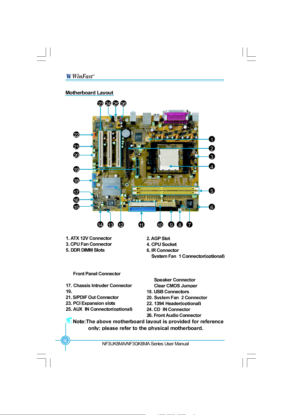
Chapter 1 Product Introduction
7. COM2 Connector(optional)
9. Floppy Disk Connector
11. IDE Connectors
13.
15. BIOS TBL Jumper
S- ATA Connectors(optional)
NF3UK8MA-NF3GK8MA-manual-V1.1.p65 2005-3-16, 17:204
8.
10. A T X Power Connector
12. Chipset: NVIDIA nForce3 Ultra/
nForce3 250 Gb
14.
16.
Page 13
Chapter 1 Product Introduction
This chapter introduces the hardware installation process,
including the installation of the CPU and memory. It also
addresses the connection of your power supply, use of the
rear panel connectors, connection of hard drive and floppy
drive data cables, and setting up various other feature of the
motherboard. Caution should be exercised during the installation process. Please refer to the motherboard layout
prior to any installation and read the contents in this chapter
carefully.
NF3UK8MA-NF3GK8MA-manual-V1.1.p65 2005-3-16, 17:205
Rear Panel Connectors
Other Connectors
Expansion Slots
Page 14
Chapter 2 Installation Instructions
NF3UK8MA-NF3GK8MA-manual-V1.1.p65 2005-3-16, 17:206
Page 15
Chapter 2 Installation Instructions
HyperTransport
TM
Technology.
Athlon
TM
64 or Athlon
TM
64 FX processors and
NF3UK8MA-NF3GK8MA-manual-V1.1.p65 2005-3-16, 17:207
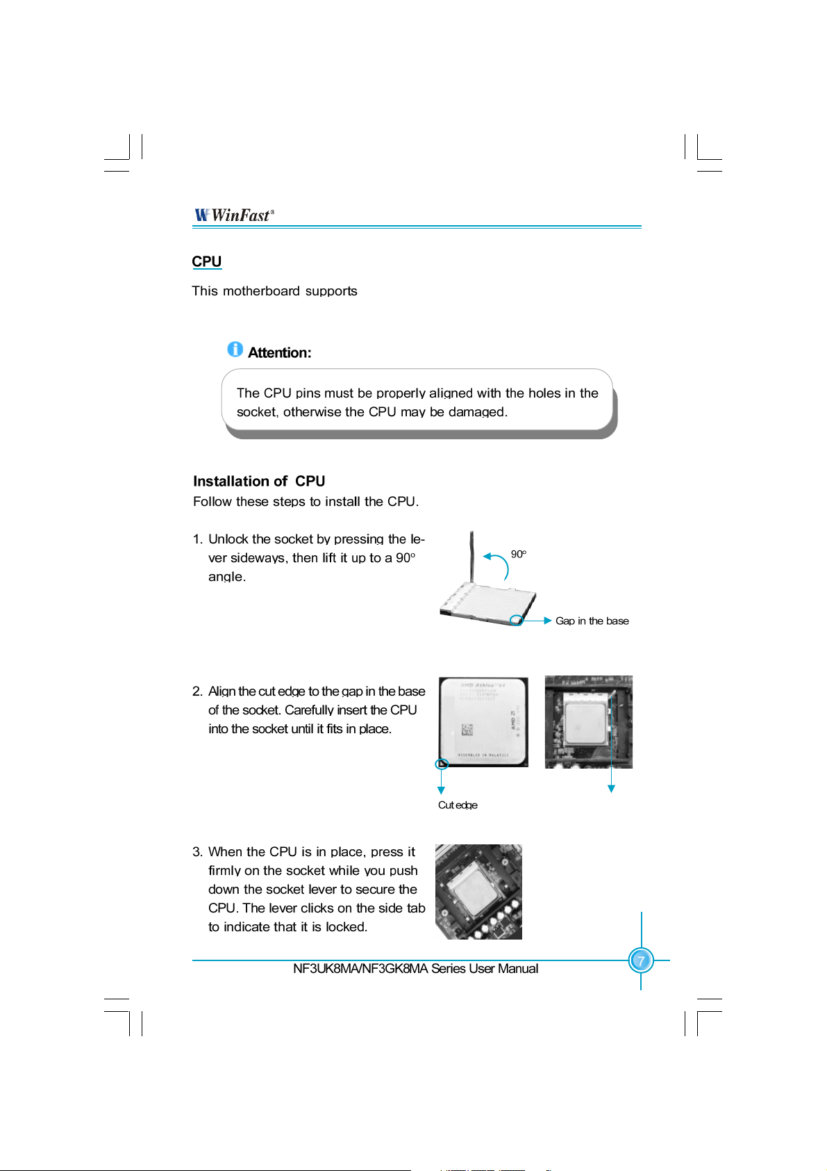
Push down the socket
lever to secure the CPU.
Page 16
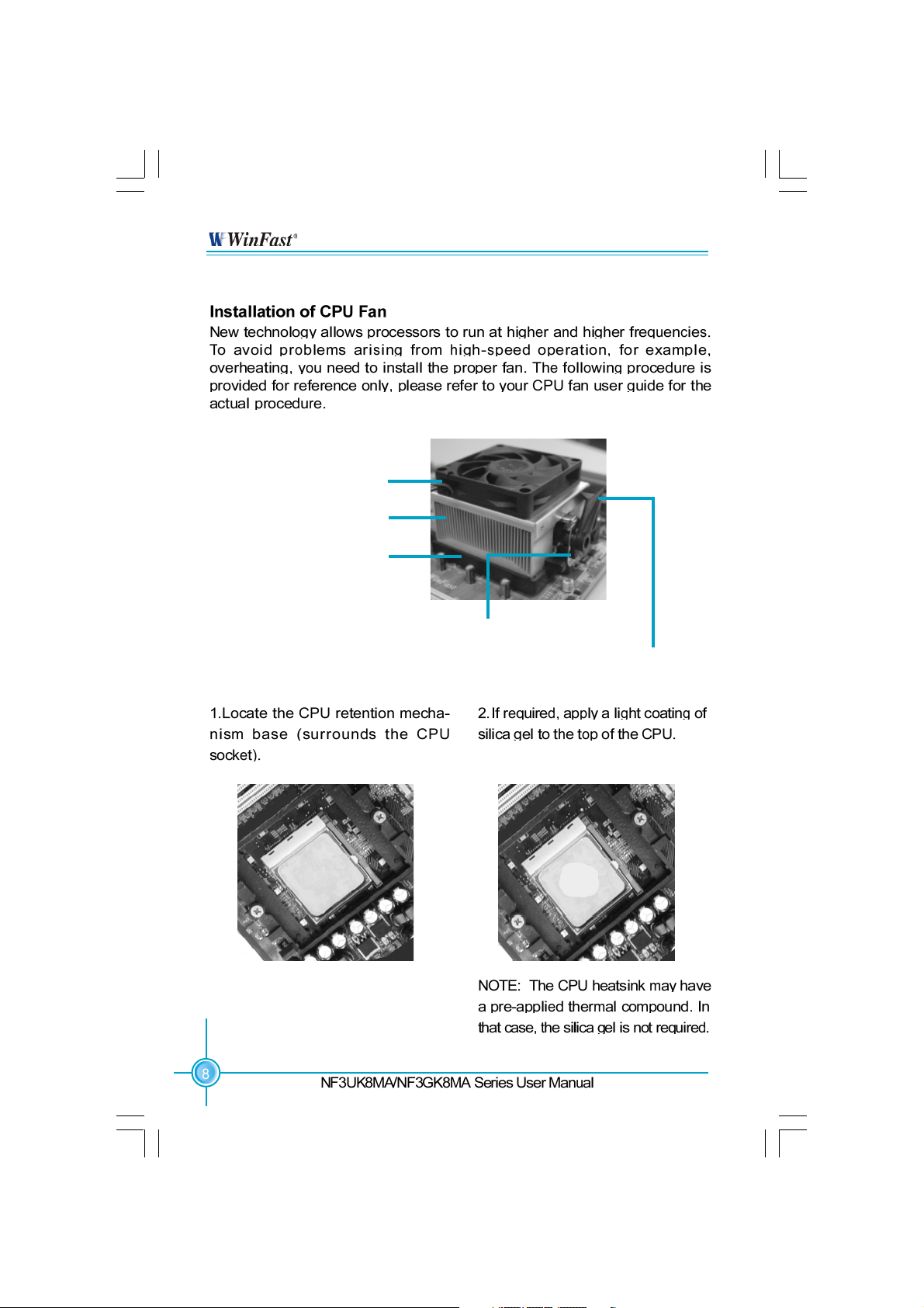
CPU Fan
CPU Heatsink
CPU Retention Mechanism
Chapter 2 Installation Instructions
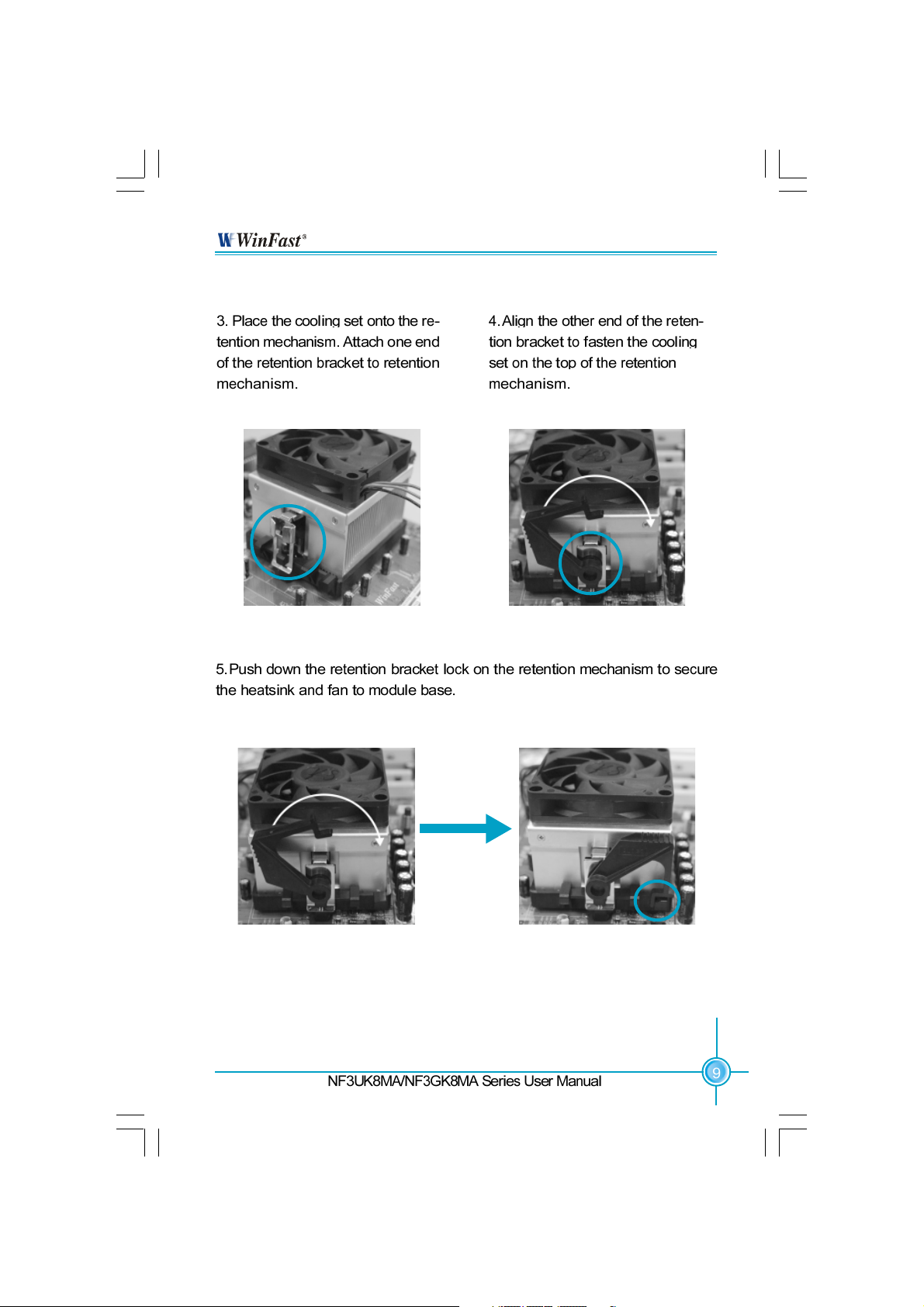
CPU Retention Bracket
CPU Retention Lock
NF3UK8MA-NF3GK8MA-manual-V1.1.p65 2005-3-16, 17:208
Page 17
Chapter 2 Installation Instructions
NF3UK8MA-NF3GK8MA-manual-V1.1.p65 2005-3-16, 17:209
Page 18
Chapter 2 Installation Instructions
NF3UK8MA-NF3GK8MA-manual-V1.1.p65 2005-3-16, 17:2010
Page 19
Chapter 2 Installation Instructions
NF3UK8MA-NF3GK8MA-manual-V1.1.p65 2005-3-16, 17:2011
Page 20
Chapter 2 Installation Instructions
Vender
CORSAIR
CORSAIR
LPT
LPT
KINGSTEK
KINGMAX
HLX
HLX
CRL
NANYA
SAMSUNG
Type
(PC3700)DDR 466
(PC4000)DDR 500
(PC3200)DDR 400
(PC4000)DDR 500
(PC2700)DDR 333
(PC2100)DDR 266
(PC2700)DDR 333
(PC2100)DDR 266
(PC2700)DDR 333
(PC2100)DDR 266
(PC3200)DDR 400
Size
256MB
256MB
512MB
256MB
512MB
256MB
256MB
256MB
512MB
128MB
128MB
NF3UK8MA-NF3GK8MA-manual-V1.1.p65 2005-3-16, 17:2012
Page 21
Chapter 2 Installation Instructions
NF3UK8MA-NF3GK8MA-manual-V1.1.p65 2005-3-16, 17:2013
Page 22

Chapter 2 Installation Instructions
NF3UK8MA-NF3GK8MA-manual-V1.1.p65 2005-3-16, 17:2114
Page 23

Chapter 2 Installation Instructions
-L
10M Data activity
10M Link
100M Data activity
100M Link
-K
100M Data activity
100M Link
Giga Data activity
Giga Link
Green LED
Blinking
Blinking once
Green LED
Blinking
Blinking
Yellow LED
Blinking
Blinking once
Dual color LED
Green
Y ellow
light
light
light
light
Green LED
Yellow LED/
Dual color LED
NF3UK8MA-NF3GK8MA-manual-V1.1.p65 2005-3-16, 17:2115
Page 24

Chapter 2 Installation Instructions
NF3UK8MA-NF3GK8MA-manual-V1.1.p65 2005-3-16, 17:2116
+ -
1
+ -
Page 25

Chapter 2 Installation Instructions
F_USB1
1394 Connector(optional): F_1394
The 1394 expansion cable can be connected to either the front (provided that the front panel of your
chassis is equipped with the appropriate interface)
or the rear panel of the chassis.
NF3UK8MA-NF3GK8MA-manual-V1.1.p65 2005-3-16, 17:2117
F_USB2
Page 26

Chapter 2 Installation Instructions
Fan Connectors: CPU_FAN, FAN_1 (optional), F AN_2
There are three fan connectors on this motherboard.
1
1
Audio Connectors: CD_IN, AUX_IN (optional)
CD_IN, AUX_IN is Sony standard CD audio
connectors, to receive audio input from the CD-ROM,
attach its audio connector to the CD_IN/AUX_IN au-
dio connectors on the motherboard.
S-ATA Connectors (optional): SATA_1, S ATA _ 2
The Serial A T A connectors are used to connect
the S-ATA devices to the motherboard. These
connectors support the thin Serial A T A cables
for primary internal storage devices. The current S-ATA interface allows up to 150MB/s data
transfer rate.
Front Audio Connector: F_AUDIO
The audio port includes two parts – the Front
Audio and Rear Audio. Their priority is sequenced from high to low (Front Audio to Rear
Audio). If headphones are plugged into the front
panel of the chassis (using the Front Audio),
then the Line Out (Rear Audio) on the rear panel
will not work. If you do not want to use the Front
Audio, pin 5 and 6, pin 9 and 10 must be short,
and then the signal will be sent to the rear audio port.
1
NF3UK8MA-NF3GK8MA-manual-V1.1.p65 2005-3-16, 17:2118
Page 27

Chapter 2 Installation Instructions
Speaker Connector: SPEAKER
The speaker connector is used to connect
speaker of the chassis.
Chassis Intruder Connector (optional): INTR
The connector connects to the chassis security
switch on the case. The system can detect the
chassis intrusion through the status of this
connector. T o utilize this function, set “Intruder
detection” to “Enabled” in the “Power Management Setup” section of the CMOS Setup.Save
and exit, then boot the operating system once to
make sure this function takes effect.
S/PDIF Out Connector: SPDIF_OUT
The S/PDIF out connector is capable of providing digital audio to external speaker or compressed AC3 data to an external Dolby digital
decoder.
Note: The empty pin of SPDIF cable should be
aligned to empty pin of S/PDIF out connector.
COM2 Connector (optional): COM2
This motherboard attached a serial connector
for your computer, you only need connect it with
cable, then link devices to cable port.
NF3UK8MA-NF3GK8MA-manual-V1.1.p65 2005-3-16, 17:2119
Page 28

Chapter 2 Installation Instructions
Vendor
COLORFUL
OMEGA
ASUS
UNIKA
ASUS
UNIKA
MSI
YINGTON
ATI
GIGABYTE
NF3UK8MA-NF3GK8MA-manual-V1.1.p65 2005-3-16, 17:2120
Type
GN4 MX 440
GF4 MX 440
GN4 MX 440
7917
V9560
FX5200
FX5200
A TI 9600
ATI9800
GN-N52128TE
Video Memory
64MB
64MB
64MB
64MB
128MB
128MB
128MB
128MB
128MB
128MB
Page 29

Chapter 2 Installation Instructions
NF3UK8MA-NF3GK8MA-manual-V1.1.p65 2005-3-16, 17:2121
Page 30

Chapter 2 Installation Instructions
Boot mode select Jumper: J3B2
The jumper is used to select between a user table
and a safe table for boot initialization parameters.
Please keep it as default setting.
Safe Mode
(Default)
User Mode
1
2
3
1
2
3
BIOS TBL Jumper: TBL_EN
The system cannot boot, if flash the BIOS fail in
conventional flash BIOS process. Y ou will no such
worry when you use the BIOS TBL function. It is
used to protect BIOS “Top Boot Block”. The system
still can boot by using this function and show some
information to recover the BIOS even if flash BIOS
fail. T o utilize this function, you just leave this jumper
as default(pin 2 and 3 together with the jumper
cap).
Note: Before you flash the BIOS, you’d better note down the MAC address, for
the MAC address maybe lose by incorrect flash operation.
Y ou can get the MAC address from a label on the Parallel Port on the
motherboard.
For example:
BIOS TBL
Enable
(Default)
BIOS TBL
Disable
1
2
3
1
2
3
EA=XXXXXXXXXXXX
After you note down the MAC address, you can reference the following process
to key in the MAC address:
1. Boot your computer, press Del to enter the BIOS Setup.
2. Select the Integrated Peripherals . Then Press Enter .
3. Enabled the Machine MAC(NV) Address.
4. Select MAC(NV) Address Input, then press Enter .
5. Input the MAC address to the open table.
For advanced user, you can modify the MAC address by the A W ARD BIOS
Flash Tool.
NF3UK8MA-NF3GK8MA-manual-V1.1.p65 2005-3-16, 17:2122
Page 31

Chapter 2 Installation Instructions
NF3UK8MA-NF3GK8MA-manual-V1.1.p65 2005-3-16, 17:2123
Page 32

This chapter tells how to change system settings through the
BIOS Setup menus. Detailed descriptions of the BIOS param-
eters are also provided.
You have to run the Setup Program when the following cases
occur:
T-- This page is intentionally left blank -- his
1. An error message appears on the screen during the
system POST process.
2. Y ou want to change the default CMOS settings.
This chapter includes the following information:
Enter BIOS Setup
Main Menu
Standard CMOS Features
BIOS Features
Advanced BIOS Features
Advanced Chipset Features
Integrated Peripherals
Power Management Setup
PnP/PCI Configurations
PC Health Status
X-BIOS II
Load Basic Defaults
Load Best Defaults
Set Supervisor/User Password
Save & Exit Setup
Exit Without Saving
NF3UK8MA-NF3GK8MA-manual-V1.1.p65 2005-3-16, 17:2124
Page 33

Chapter 3 BIOS Description
Note:
We do not suggest that you change the default parameters in the
BIOS Setup, and we shall not be responsible for any damage that
results from any changes that you make.
The items in the BIOS Setup main menu are explained below:
Standard CMOS Features
The basic system configuration can be set up through this menu.
BIOS Features
The general system features can be set up through this menu.
NF3UK8MA-NF3GK8MA-manual-V1.1.p65 2005-3-16, 17:2125
Page 34

Chapter 3 BIOS Description
NF3UK8MA-NF3GK8MA-manual-V1.1.p65 2005-3-16, 17:2126
Page 35

Chapter 3 BIOS Description
NF3UK8MA-NF3GK8MA-manual-V1.1.p65 2005-3-16, 17:2127
Page 36

Chapter 3 BIOS Description
NF3UK8MA-NF3GK8MA-manual-V1.1.p65 2005-3-16, 17:2128
Page 37

Chapter 3 BIOS Description
NF3UK8MA-NF3GK8MA-manual-V1.1.p65 2005-3-16, 17:2129
Page 38

Chapter 3 BIOS Description
NF3UK8MA-NF3GK8MA-manual-V1.1.p65 2005-3-16, 17:2130
Page 39

Chapter 3 BIOS Description
Hard Disk Boot Priority
This option is used to select the priority for HDD startup. After pressing
<Enter>, you can select the HDD using the <PageUp>/<PageDn> or Up/Down
arrow keys, and change the HDD priority using <+> or <->. To exit this option,
press <Esc>.
This option is used to set up the virus warning message for the IDE HDD boot
sector. When enabled, a warning message will appear on the screen if any
program intend s to write information to the boot sector . The available setting
values are: Disabled and Enabled.
Note: Such function provides protection to the startup sector only; it does not
protect the entire hard disk.
NF3UK8MA-NF3GK8MA-manual-V1.1.p65 2005-3-16, 17:3531
Page 40

Chapter 3 BIOS Description
This option is used to select the system performance. If it is set to “Optional”,
BIOS will use the most stable settings. If it is set to “Aggressive”, BIOS will use
over clocked settings for higher performance but with higher risk of instability.
If it is set to “Expert”, BIOS allows full customization of performance options.
Advanced users only.
Max Memclock (MHz)
When it is set to Manual in “DDR T iming Setting by”, user can place an Artificial
memory clock limit on the system. Memory is prevented from running faster
than this frequency. The available setting values are: 100, 133, 166, 200, Auto.
CAS# Latency (Tcl)
This option controls the CAS latency, which determines the timing delay (in
clock cycles) before SDRAM starts a read command after receiving it. The avail-
able setting values are: Auto, 2.0, 2.5, 3.0.
NF3UK8MA-NF3GK8MA-manual-V1.1.p65 2005-3-16, 17:3532
Page 41

Chapter 3 BIOS Description
RAS# to CAS# delay (Trcd)
When DRAM is refreshed, both rows and columns are addressed separately.
This setup item allows you to determine the timing of the transition from RAS
(row address strobe) to CAS (column address strobe). The less the clock cycles,
the faster the DRAM performance. The available setting values are: Auto, 2 - 7.
Row Precharge Time (T rp)
This item controls the number of cycles for Row Address Strobe (RAS) to be
allowed to precharge. If insufficient time is allowed for the RAS to accumulate
its charge before DRAM refresh, refreshing may be incomplete and DRAM may
fail to retain data. This item applies only when synchronous DRAM is installed
in the system. The available setting values are: Auto, 2 - 6.
This feature is especially designed for AMD Athlon processor, which provides
a CPU temperature detecting function to prevent your CPU from overheating
due to the heavy working loading. The available setting values are: Disabled,
Auto.
NF3UK8MA-NF3GK8MA-manual-V1.1.p65 2005-3-16, 17:3533
Page 42

Chapter 3 BIOS Description
1T/2T Memory Timing (Default: Auto)
This setting controls the SDRAM command rate. Selecting [Auto] allows SDRAM
signal controller to run at 1T (T=clock cycles) rate. Selecting [1T] makes SDRAM
signal controller run at 2T rate. 1T is faster than 2T. The available setting values
are: 1T, 2T , Auto.
NF3UK8MA-NF3GK8MA-manual-V1.1.p65 2005-3-16, 17:3534
Page 43

Chapter 3 BIOS Description
NF3UK8MA-NF3GK8MA-manual-V1.1.p65 2005-3-16, 17:3535
Page 44

Chapter 3 BIOS Description
POWER ON Function (Default: BUTTON ONLY)
This option is used to set the power on method for your PC. Setting values
include: Password, Hot KEY, Mouse Move, Mouse Click, Any KEY, BUTTO N
ONLY and Keyboard98.
KB Power ON Password (Default: Enter)
When the POWER ON Function is set to Password, use this item to set the
password.
Hot Key Power ON (Default: Ctrl-F1)
When the POWER ON Function is set to Hot KEY, use this item to set the hot
key combination that turns on the system. The available setting values are:
Ctrl-F1-F12.
Onboard Serial Port 1/2 (Default: 3F8/IRQ4/2F8/IRQ3)
This option is used to assign the I/O address and interrupt request (IRQ)
for the onboard serial port 1/2.
Note: Do not try to set the same values for serial port 1 and 2.
UART Mode Select (Default: Normal)
Use this option to select the UART mode. The setting values include Normal,
IrDA, ASKIR and SCR. The setting value is determined by the infrared module
installed on the board.
UR2 Duplex Mode (Default: Half)
This option is available when UAR T 2 mode is set to either ASKIR or IRDA.
This option enables you to determine the infrared (IR) function of the onboard
infrared chip. The available setting values are: Half and Full.
Onboard Parallel Port (Default: 378/IRQ7)
This option is used to assign the I/O address and interrupt request (IRQ) for
onboard parallel port controller. The setting values include: Disabled, 378/
IRQ7, 278/IRQ5 and 3BC/IRQ7.
Parallel Port Mode (Default: SPP)
Select an address and corresponding interrupt for the onboard parallel port.
The setting values include SPP, EPP, ECP, ECP+EPP.
PWRON After PWR-Fail (Default: Off)
This option is used to set what action the PC will take with the power supply
when it resumes after a sudden power failure. The available options are: Off
(remain in turn off status). On (auto power on) and Former-Sts (resume with
the previous status).
NF3UK8MA-NF3GK8MA-manual-V1.1.p65 2005-3-16, 17:4336
Page 45

Chapter 3 BIOS Description
NF3UK8MA-NF3GK8MA-manual-V1.1.p65 2005-3-16, 17:3737
Page 46

Chapter 3 BIOS Description
NF3UK8MA-NF3GK8MA-manual-V1.1.p65 2005-3-16, 17:3738
Page 47

Chapter 3 BIOS Description
ACPI stands for “Advanced Configuration and Power Interface”. ACPI is a
standard that defines power and configuration management interfaces between an operating system and the BIOS. In other words, it is a standard that
describes how computer components work together to manage system
hardware. In order to use this function the ACPI specification must be supported by the OS (for example, Windows2000 or WindowsXP). The available
setting values are: Enabled and Disabled.
This option is used to set the energy saving mode of the ACPI function.
When you select “S1 (P O S)” mode, the power will not shut off and the
supply status will remain as it is, in S1 mode the computer can be resumed
at any time. When you select “S3 (STR)” mode, the power will be cut off after
a delay period. The status of the computer before it enters STR will be saved
in memory, and the computer can quickly return to the previous status when
the STR function wakes. When you select “S1 & S3” mode, the system
will automatically select the delay time.
This option is used to set the power management scheme. A vailable settings
are: User Define, Min Saving and Max Saving.
NF3UK8MA-NF3GK8MA-manual-V1.1.p65 2005-3-16, 17:3739
Page 48

Chapter 3 BIOS Description
This option is used to turn off hard disk power if the hard disk is idle for a given
period of time. The setting values are Disabled and 1Min-15Min.
This option is used to define the continuous HDD idle time before the HDD
enters power saving mode. The setting values are Disabled and Enabled.
PBTN (Default: Instant-Off)
This option is used to set the power down method. This function is only valid
for systems using an A TX power supply. When “Instant-Off” is selected, press
the power switch to immediately turn off power. When “Delay 4 Sec.” is
selected, press and hold the power button for four seconds to turn off power.
(Default: Disabled)
This option is used to enable or disable the feature of booting up the system
on a scheduled time/date. The setting values are Disabled and Enabled.
When the Power-On by Alarm set as “Enabled”, this option will be modified. It
is used to set the timing for the start-up date. The setting values contain 0 - 31.
When the Power-On by Alarm set as “Enabled”, this option will be modified. It
is used to set the timing for the start-up date. The setting values contain hh: 023; mm: 0-59; ss: 0-59.
This option is used to enable or disable intruder detection function. The setting values are: Disabled and Enabled.
NF3UK8MA-NF3GK8MA-manual-V1.1.p65 2005-3-16, 17:3740
Page 49

Chapter 3 BIOS Description
This option is used to set whether the system is permitted to automatically
distribute IRQ DMA and I/O addresses each time the machine is turned on.
The setting values are: Disabled and Enabled.
This option is used to define the system resource control scheme. If all cards
you use support PnP, then select Auto (ESCD) and the BIOS will automatically
distribute interruption resources. If the ISA cards you installed not supporting PnP, you will need to select “Manual” and manually adjust interruption
resources in the event of hardware conflicts. However, since this motherboard
has no ISA slot, this option does not apply.
Press the <Enter> key, then manually set IRQ resources.
NF3UK8MA-NF3GK8MA-manual-V1.1.p65 2005-3-16, 17:3341
Page 50

Chapter 3 BIOS Description
This option is used to set the system temperature upper limit. When the
temperature exceeds the setting value, the motherboard will automatically
cut off power to the computer. The available setting values are: 60oC/140oF,
o
65
C/149oF, 70oC/1 58oF and Disabled.
NF3UK8MA-NF3GK8MA-manual-V1.1.p65 2005-3-16, 17:3342
Page 51

Chapter 3 BIOS Description
This option is used to set the memory voltage. The available setting values
are: 2.80V, 2.70V, 2.50V, Default.
NF3UK8MA-NF3GK8MA-manual-V1.1.p65 2005-3-16, 17:3343
Page 52

Chapter 3 BIOS Description
NF3UK8MA-NF3GK8MA-manual-V1.1.p65 2005-3-16, 17:3344
Page 53

Chapter 3 BIOS Description
NF3UK8MA-NF3GK8MA-manual-V1.1.p65 2005-3-16, 17:3345
Page 54

The utility CD that came with the motherboard contains useful
software and several utility drivers that enhance the mother-
board features.
Utility CD content
Start to install drivers
NF3UK8MA-NF3GK8MA-manual-V1.1.p65 2005-3-16, 17:3346
Page 55

Chapter 4 Driver CD Introduction
Utility CD content
This motherboard comes with one Utility CD. To begin using the CD, simply insert
the CD into your CD-ROM drive r. The CD will automatically display the main menu
screen.
NF3UK8MA-NF3GK8MA-manual-V1.1.p65 2005-3-16, 17:3347
Page 56

Chapter 4 Driver CD Introduction
Select <Install Driver> to enter the driver installation menu (as following pic).
Click the relevant button to install NVIDIA nForce Chipset System, DirectX 9.0b,
Audio Driver, USB2.0 Driver.
NF3UK8MA-NF3GK8MA-manual-V1.1.p65 2005-3-16, 17:3348
Page 57

Chapter 4 Driver CD Introduction
NF3UK8MA-NF3GK8MA-manual-V1.1.p65 2005-3-16, 17:3349
Page 58

Chapter 5 NVIDIA RAID Introduction
RAID Arrays
This section describes the following types of RAID arrays that NVIDIA RAID
supports:
• RAID 0
RAID 0 defines a disk striping scheme that improves the disk read and write
times for many applications.
• RAID 1
RAID 1 defines techniques for mirroring data.
• RAID 0+1
RAID 0+1 combines the techniques used in RAID 0 and RAID 1 arrays.
• Spanning (JBOD)
JBOD provides a method for combining drives of different sizes into one large
disk.
Summary of RAID Configurations
Array
High data throughput.
RAID 0
100% data redund-
RAID 1
ancy.
Optimized for both
RAID
100% data redun-
0+1
dancy and per-
formance. Allows
spare disks.
Combines and uses
JBOD
the capacity of odd
size drives.
Advantages
Drawbacks
No fault tolerance.
Requires two drives
for the storage space
of one drive.
Requires two drives
for the storage space
of one drive—the
same as RAID level 1.
Decreases perfor-
mance because of the
difficulty in using drives
concurrently or to op-
timize drives for differ-
ent uses.
# Hard Disks
multiple
2
4+
multiple
Fault Tolerance
None
Yes
Yes
No
NF3UK8MA-NF3GK8MA-manual-V1.1.p65 2005-3-16, 17:3350
Page 59

Chapter 5 NVIDIA RAID Introduction
Basic Configuration Instructions
The following are the basic steps for configuring NVIDIA RAID:
Non-Bootable RAID Array
1. Choose the hard disks that are to be RAID enabled in the system BIOS.
2. Specify the RAID level, either Mirroring (RAID 1), Striping (RAID 0), Stripe Mirroring
(RAID 0+1), or Spanning (JBOD) and create the desired RAID array.
3. Install the operating system on one hard disk, then reboot the computer.
4. Run the Windows nForce Setup application and install the RAID driver.
5. Initialize the NVRAID Array.
Bootable RAID Array
1. Choose the hard disks that are to be RAID enabled in the system BIOS.
2. Specify the RAID level, either Mirroring (RAID 1), Striping (RAID 0), Mirrored Striping
(RAID 0+1), or Spanning (JBOD) and create the desired RAID array.
3. Boot from the Windows CD, then press F6 when the Windows Setup appears.
4. Insert the RAID driver floppy to Install the nForce RAID driver.
5. Initialize the NVRAID Array.
NF3UK8MA-NF3GK8MA-manual-V1.1.p65 2005-3-16, 17:3351
Page 60

Chapter 5 NVIDIA RAID Introduction
Setting Up the BIOS
1. Start up the computer, then press Delete to enter the BIOS setup. Use the arrow
keys to select Integrated Peripherals , then press Enter .
2. Use the arrow keys to select the RAID Config, then press Enter .
3. From the RAID Config window, enabled the IDE RAID, the other items would be
light, then you can enable the disk that you want to use as RAID disks.
4. Press F10 to save the configuration and exit.
NF3UK8MA-NF3GK8MA-manual-V1.1.p65 2005-3-16, 17:3452
Page 61

Chapter 5 NVIDIA RAID Introduction
Entering the RAID BIOS Setup
1. After rebooting your PC, wait until you see the RAID software prompting you to
press F 1 0 . The RAID prompt appears as part of the system POST and boot process
prior to loading OS.
2. Press F 1 0 , and the NVIDIA RAID Utility --- Define a New Array window will appear.
The default RAID Mode is set to Mirroring and the default Striping Block is set to
Optimal.
Understanding the “Define a New Array” Window
Use the Define a New Array window to
• Select the RAID Mode
• Set up the Striping Block
• Specify which disks to use for the RAID Array
Depending on the platform used, the system have one or more channels. In a
typical system there are usually one controller and multiple channels, and each
channel have a slave and a master.
The channel/controller/master/slave status of each hard disk is given in the Loc
(location) columns of the Free Disks and Array Disks lists.
1. 0. M
NF3UK8MA-NF3GK8MA-manual-V1.1.p65 2005-3-16, 17:3453
M: Master
S: Slave
0: Controller
Channel - Typically , channel 0 is used for
Parallel A T A drivers while channel 1 is used
for Serial A T A drives.
Page 62

Chapter 5 NVIDIA RAID Introduction
In the example above, 1.0.M means the hard drive is attached to Channel 1, Control-
ler 0, and the drive is set to Master. The following is a list of all possible combinations:
Parallel A T A
0.0.M Channel 0, controller 0, Master
0.0.S Channel 0, controller 0, Slave
0.1.M Channel 0, controller 1, Master
0.1.S Channel 0, controller 1, Slave
Serial A T A
1.0.M Channel 1, controller 0, Master
1.1.M Channel 1, controller 1, Slave
Note: There is no such thing as Slave drive in Serial A T A. All drives are considered to
be Master since there is a one to one connection between the drive and the controller.
Using the Define a New Array Window
If necessary, press the tab key to move from field to field until the appropriate field is
high lighted.
• Selecting the RAID Mode
By default, this is set to [Mirroring]. Change to a different RAID mode, press the
down arrow keys until the mode that you want appears in the RAID Mode box—
either [Mirroring], [Striping], [Spanning], or [Stripe Mirroring].
• Selecting the Striping Block Size
Striping Block size is given in kilobytes, and affects how data is arranged on the
disk. It is recommended to leave this value at the default [Optimal], which is 32KB,
but the values can be between [4 KB] and [128 KB].
NF3UK8MA-NF3GK8MA-manual-V1.1.p65 2005-3-16, 17:3454
Page 63

Chapter 5 NVIDIA RAID Introduction
• Assigning the Disks
The disks that you enabled from the RAID Config BIOS setup page appear in the
Free Disks block. These are the drives that are available for use as RAID array.
To designate a free disk to be used as a RAID array:
1. Tab to the F ree Disks section. The first disk in the list is selected.
2. Move it from the Free Disks block to the Array Disks block by pressing the right
arrow key ( ). The first disk in the list is moved, and the next disk in the list is
selected and ready to be moved.
3. Continue pressing the right-arrow key (
as RAID array appear in the Array Disks block.
) until all the disks that you want to use
It shows that two disks have been assigned as RAID1 array disks in the figure
above.
Completing the RAID BIOS Setup
1. After assigning your RAID array mode, press F7. The Clear disk data windows
prompt appears.
NF3UK8MA-NF3GK8MA-manual-V1.1.p65 2005-3-16, 17:3455
Page 64

Chapter 5 NVIDIA RAID Introduction
2. Press Y if you want to wipe out all the data from the RAID array, otherwise press
N. Y ou must choose Y es if the drives were previously used as RAID drives.
The Array List window appears, where you can review the RAID arrays that you
have set up.
3. Use the arrow keys to select the array that you want to set up, then press Enter.
The Array Detail window appears.
4. If you want to mark this disk as empty and wipe out all its contents then press C .
5. At the prompt, press Y to wipe out all the data, otherwise press N .
6. Press Enter again to go back to the previous window and then press Ctrl+X to exit
the RAID setup.
NF3UK8MA-NF3GK8MA-manual-V1.1.p65 2005-3-16, 17:3456
Page 65

Chapter 5 NVIDIA RAID Introduction
NVIDIA RAID Utility Installation
Installing the NVIDIA RAID Software Under Windows (for Non-bootable RAID Array)
This section describes how to setup the application and install the RAID software
which will upgrade the Windows IDE driver and install the RAID driver.
1. Start the nForce Setup program to open the NVIDIA Windows nForce Drivers
page.
2. Select the modules that you want to install. Select the relative options that you
have configured.
3. Click Next and then follow the instructions.
4. After the installation is completed, be sure to reboot the PC.
5. After the reboot, initialize the newly created array .
NF3UK8MA-NF3GK8MA-manual-V1.1.p65 2005-3-16, 17:3457
Page 66

Chapter 5 NVIDIA RAID Introduction
Installing the RAID Driver (for bootable RAID Array)
1. After you complete the RAID BIOS setup, boot from the W indows CD, and the W indows
Setup program starts.
2. Press F6 and wait for the Windows Setup screen to appear.
3. Specify the NVIDIA drivers:
(1) Insert the floppy that has the RAID driver, press S, then press Enter. The Windows Setup
screen appears as below:
(2) Select “NVIDIA RAID CLASS DRIVER” and then press Enter .
(3) Press S again at the Specify Devices screen, then press Enter.
(4) Select “NVIDIA NForce Storage Controller” and then press Enter. The following Windows
Setup screen appears listing both drivers:
NF3UK8MA-NF3GK8MA-manual-V1.1.p65 2005-3-16, 17:3458
Page 67

Chapter 5 NVIDIA RAID Introduction
4. Press Enter to continue with operating system Installation. Be sure to copy the
files from the floppy is complete, then take out the floppy.
5. Follow the instructions on how to install operating system. During the GUI portion
of the installation you might be prompted to click Y es to install the RAID driver . Click
Y es as many times as needed in order to finish the installation. This will not be an
issue with a signed driver.
Note: Each time you add a new hard drive to a RAID array, the RAID driver will have
to be installed under W indows once for that hard drive. After that, the driver will not
have to be installed.
NF3UK8MA-NF3GK8MA-manual-V1.1.p65 2005-3-16, 17:3459
Page 68

Chapter 5 NVIDIA RAID Introduction
Initializing and Using the Disk Array
The RAID array is now ready to be initialized under Windows.
1. Launch Computer Management by clicking “Start” —> “Settings” —> “Control
Panel” then open the “Administrative T ools” folder and double click on “Computer
Management”.
2. Follow screen instructions to install. While finished, the “Computer Manage-
ment” window appears.
The actual disks listed will depend on your system, and the unallocated partition is
the total combined storage of two hard disks. Y ou must format the unallocated disk
space in order to use it.
3. Format the unallocated disk space. Right click “Unallocated space”, select “New
Partition…” and follow the wizard. After the drive has been formatted, it is ready for
use.
NF3UK8MA-NF3GK8MA-manual-V1.1.p65 2005-3-16, 17:3460
Page 69

Chapter 5 NVIDIA RAID Introduction
Win2K Limitation with Bootable RAID
In Windows 2000 (Service Pack 2 or previous versions), the end user cannot install
this operating system to a bootable RAID volume.
There are two solutions to resolve this issue.
I) Use the NVRAID Tool to convert the boot volume to a RAID array.
Here are the detailed step by step instructions:
1. Install Windows 2000 on a selected hard drive.
2. Download and install Windows 2000 Service Pack 4 from Microsoft’s website.
3. Reboot the system, press the DEL key as the system is rebooting to enter into the
system BIOS.
4. Select Integrated Peripherals
5. Enable RAID Config for the selected drive (the one containing the Windows 2000
operating system). Then press F10 to exit and save settings in the system BIOS
(This action reboots the System).
6. Press F10 as the system is rebooting to go into the RAID ROM(The system
directs you into the NVIDIA RAID Utility).
7. Select Striping under RAID Mode. Press TA B to go into the Free Disk menu. You
can use the Right Arrow key to add the desired disk.
8. After that, Press F7 to finish. Select N (NO) when asked to Clear Disk Data .
9. Then Press Ctrl-X t o exit.The system reboots into Windows 2000.
10. Install the NVIDIA nForce Driver Package while in Windows 2000. Then reboot
the system.
11. Go to S TART>Programs>Nvidia Corporation and select NVRAID Manager. You
should see the single disk RAID array (in striping mode) that was created from the
boot disk.
12. Select the single boot disk RAID Array by clicking on it.
13. Select Convert Array under the System Tasks. The Convert Array wizard is
displayed. Then Select Next.
RAID Config.
NF3UK8MA-NF3GK8MA-manual-V1.1.p65 2005-3-16, 17:3461
Page 70

Chapter 5 NVIDIA RAID Introduction
14. Select the desired type of RAID array you want to convert. Then Select Next.
15. Y ou are prompted to select the desired Free Disk(s) to add to the bootable RAID
array. Click Finish .
At this point, NVRAID starts converting the single disk RAID array into a multi-disk
RAID array in a bootable format.
Note: Conversion may take 1-2 hours depending on disk size.
II) The user must create a combination installation CD that includes Windows
2000 and SP3 or SP4 fixes integrated in. To create the combination installation
CD, refer to the following website:
http://www.microsoft.com/windows2000/downloads/servicepacks/sp4/HFdeploy.
htm
Note: If the end user chooses not to install Windows 2000 Service Pack 3 or 4, RAID
is still supported on Windows 2000. However, the end user will not be able to create
a bootable RAID volume.
NF3UK8MA-NF3GK8MA-manual-V1.1.p65 2005-3-16, 17:3462
 Loading...