

Forney 250P+ Operating Manual
1
WWW.FORNEYIND.COM
CAT# 317
FEATURES:
• Uses Electrical Arc Drag Torch Technology
that allows you to move (drag) torch
directly across the metal surface for more
precise cuts
• Cuts up to 1/8” mild steel and severs up to
1/4” steel
• Easy to use and operate
• Uses standard household 120 VAC current
• Plasma cutter comes with a built-in air
compressor and lightweight inverter power
supply
• Thermal overload protection
• Three diagnostic LED lights
• Post-flow air cooling for longer life
• Internal cooling fan
• CSA certified
IDEAL FOR:
Auto Body, Farm & Ranch, Sheet Metal,
HVAC, Plumbing, Contractor, and more...
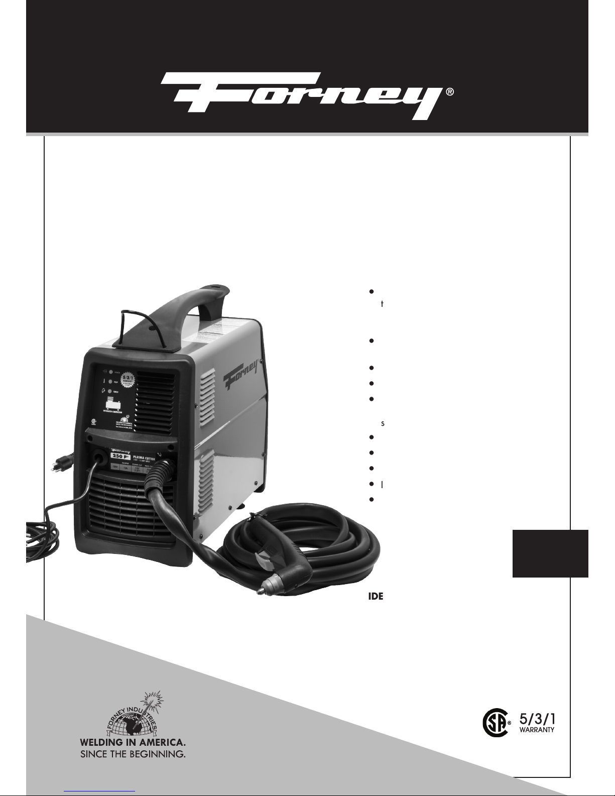
INCLUDES:
Torch, Ground Cable, Ground Clamp, Box of
Consumables, and Input Power Cable.
250P+ PLASMA CUTTER
WITH BUILT-IN AIR COMPRESSOR
OPERATING MANUAL
ENGLISH
REV 08.25.15

2
WWW.FORNEYIND.COM
STOP!
PLEASE DO NOT
RETURN TO THE STORE
If you have questions or problems with your new plasma cutter,
please call customer service at 1-800-521-6038
Monday through Friday from 7 a.m. - 5 p.m. (MST) or at
www.forneyind.com/customer_service.
Please take time to register your product at
www.forneyind.com/customer_service/register_your_product/
Thank you, enjoy your new plasma cutter.

3
WWW.FORNEYIND.COM
Forney Promise
We are committed to your success regardless of location, size or
needs. We understand it is your goal to get the job done right,
and we are ready to help you do just that.
President's Message
We market the highest quality tools, equipment and accessories
for the do-it-yourselfer and professional. Our passion and
dedication in bringing new products to the industrial and retail
market, combined with our personal service, is unmatched in our
industry. Our ability to listen to our customers’ needs enables us to
create solutions to their problems.
Our dedication to the highest quality customer service within our
corporate headquarters and the service provided in the field is
unequaled. We are committed to creating the best solutions to our
customer’s needs. Above all, our employees will provide the same
respect and caring attitude within the organization as they are
expected to share with every Forney customer. Our goal will be to
exceed our customers’ expectations through empowered people,
guided by shared values and commitments.
We work hard so our customers trust us because of our integrity,
teamwork and innovation of Forney products, and Forney’s
80 years of unmatched product quality and an unwavering
commitment to our customers.
When our customers succeed we succeed.
STEVEN G. ANDERSON, President & CEO
Copyright© 2014 Forney Industries,
Inc. All rights reserved. Unauthorized
reproduction and/or distribution is
subject to US copyright laws.
U.S. Warehouses:
- Fort Collins, CO
- Tipp City, OH
FIVE WAYS TO ORDER
Web: www.forneyind.com
Phone: 80 0-521-6038
Fax: 970-498-9505
Mail: Forney Industries
2057 Vermont Drive
Fort Collins, CO 80525
Email: sales@forneyind.com

4
WWW.FORNEYIND.COM
Forney 5/3/1 Limited Warranty
Effective July 1, 2015
1) Limited Warranty - Subject to the terms and conditions below, Forney Industris, Inc., Fort Collins,
Colorado, warrants to its original retail purchaser that the new Forney equipment sold after the effective date
of this limited warranty is free of defects in material and workmanship at the time it is shipped by Forney. This
is in lieu of all other warranties, expressed or implied.
2) Notifications: Please call 1-800-521-6038 with your warranty questions. You can also visit:
www.forneyind.com for additional information about your new welder or plasma system.
3) Length of Warranty: Within the warranty periods listed below, Forney will repair or replace any
warranted parts or components that fail due to defects in material or workmanship. Warranty is effective
from the date of original retail purchase. Warranty duration is as follows.
A) 5 years: Original main power rectifiers only to include SCRs, diodes and discrete rectifier modules,
transformers, stabilizers, and reactors.
B) 3 years: Drive Systems, PC Boards, Motors, and Switches and Controls
C) 1 year: MIG guns, relays, contactors, and regulators, plasma cutting torches, and accessories.
D) 90 days: Replacement parts. Does not include labor.
4) Forney’s limited warranty shall not apply to consumables such as contact tips, cutting nozzles, felt wire
cleaner, drive rollers, gas diffusers, plasma torch tips and electrodes, weld cables, tips and parts that fail
due to normal wear. In addition, this warranty does not extend to any damage caused by the untimely
replacement or maintenance of any of the previously listed consumable parts.
5) Warrantor:
Forney Industries
2057 Vermont Drive
Fort Collins, CO 80525
1-800-521-6038
www.forneyind.com
6) Purchaser / Warranty: The original purchaser of the Forney Industries product. The warranty is
not transferable. Forney Industries products are intended for purchase and use by persons trained and
experienced in the use and maintenance of welding equipment.
7) What is not covered under the warranty:
A) Implied warranties, including those of merchantability and fitness for a particular purpose are limited in duration
to this express warranty. After this period, all risk of loss, from whatever reason, shall be on the purchaser.
B) Any incidental, indirect, or consequential loss, damage, or expense that may result from any defect,
failure or malfunction of the Forney product.
C) Any failure that results from accident, purchaser’s abuse, neglect or failure to operate products in
accordance with instructions provided in the owner’s manual(s) supplied with the product.
D) Pre-delivery service, i.e. assembly and adjustment.
8) Claim: In the event of a warranty claim under this warranty, the exclusive remedies shall be, at Forney
Industries sole option:
A) Repair; or
B) Replacement; or
C) Where authorized in writing by Forney Industries, the cost of repair or replacement at an authorized
Forney Industries service station; or
D) Payment of or credit for the purchase price less reasonable depreciation based on actual use upon the
return of the goods at the customer’s risk and expense.
9) Purchaser will:
A) Contact Forney’s customer service at 1-800-521-6038 within 30 days of the defect or failure.
B) Provide dated proof of purchase (typically a purchase receipt).
C) Provide the serial number. Registering your welder at forneywelding.forneyind.com will speed up this process.
D) Deliver or ship welder to a Forney authorized service center. Freight &/or packaging costs, if any, must
be borne by the purchaser.
5
WWW.FORNEYIND.COM
CAUTION!
BEFORE INSTALLING, OPERATING OR CARRYING OUT MAINTENANCE ON THE MACHINE, READ THE CONTENTS OF THIS MANUAL
CAREFULLY, PAYING PARTICULAR ATTENTION TO THE SAFETY RULES AND HAZARDS.
In the event of these instructions not being clear, please contact your
Forney Authorized Dealer or Forney Customer Service 1-800-521-6038
Means: Warning! Watch Out! There are possible hazards with this procedure! The
possible hazards are shown in the adjoining symbols.
NOTE:
Means: “Note”; not safety related.
This group of symbols means: Warning! Watch Out! Possible electric shock, moving
parts, and hot parts hazards. Consult symbols and related instructions below for
necessary actions to avoid the hazards.
California Proposition 65 Warning
This product may contain chemicals known to the State of California to cause cancer, birth defects and
other reproductive harm (CA. Prop 65). Wash hands after use.
• Safety in Welding and Cutting, ANSI Standard Z49.1, from American Welding Society,
8669 Doral Boulevard, suite 130, Doral, FL 33166 Safety and Health Standards, OSHA
29 CFR 1910, from Superintendent of Documents, U.S. Government Printing Office,
Washington, D.C. 20402.
• Recommended Practices for Plasma Arc Cutting, American Welding Society Standard AWS
C5.2, from American Welding Society, 8669 Doral Boulevard, suite 130, Doral, FL 33166
• Recommended Safe Practices for the Preparation for Welding and Cutting of Containers That
Have Held Hazardous Substances, American Welding Society Standard AWS F4.1, from
American Welding Society, 8669 Doral Boulevard, suite 130, Doral, FL 33166
• National Electrical Code, NFPA Standard 70, from National Fire Protection Association,
Batterymarch Park, Quincy, MA 02269.
• Safe Handling of Compressed Gases in Cylinders, CGA Pamphlet P-1, from Compressed
Gas Association, 1235 Jefferson Davis Highway, Suite 501, Arlington, VA 22202.
• Code for Safety in Welding and Cutting, CSA Standard W117.2, from Canadian Standards
Association, Standards Sales, 178 Rexdale Boulevard, Rexdale, Ontario, Canada M9W
1R3.
• Safe Practices For Occupation And Educational Eye And Face Protection, ANSI Standard
Z87.1, from American National Standards Institute, 1430 Broadway, New York, NY 10018.
• Cutting And Welding Processes, NFPA Standard 51B, from National Fire Protection
Association, Batterymarch Park, Quincy, MA 02269
Symbol Usage
Principal Safety Standards
Safety Summary

6
WWW.FORNEYIND.COM
EMF Information
Considerations about Welding or Cutting and the Effects of Low Frequency Electric and Magnetic Fields
Welding or cutting current, as it flows through the welding or cutting cables, will cause electromagnetic
fields. There has been and still is some concern about such fields. However, after examining more than
committee of the National Research Council concluded that: “The body of evidence, in the committee’s
judgment, has not demonstrated that exposure to power-frequency electric and a magnetic field is a
human health hazard.” However, studies are still going forth and evidence continues to be examined.
Until the final conclusions of the research are reached, you may wish to minimize your exposure to
electromagnetic fields when welding or cutting.
To reduce magnetic fields in the workplace, use the following procedures:
1. Keep cables close together by twisting or taping them.
2. Arrange cables to one side and away from the operator.
3. Do not coil or drape cables around your body.
4. Keep cutting power source and cables as far away from operator as practical.
5. Connect work clamp to work piece as close to the cut as possible.
ABOUT PACEMAKERS & HEARING AIDS:
Pacemaker & Hearing Aid wearers consult your doctor first. If cleared by your doctor, then following
the above procedures is recommended.
Plasma Arc Cutting Hazards
CUTTING CAN CAUSE FIRE OR EXPLOSION.
Hot metal and sparks blow out from the cutting arc. The flying sparks and hot metal, hot work
piece, and hot equipment can cause fires and burns. Check and be sure the area is safe before
doing any cutting.
• Do not cut where flying sparks can strike flammable material.
• Connect work cable to the work as close to the cutting area as practical to prevent cutting
current from traveling long, possibly unknown paths and causing electric shock and fire
hazards.
• Never cut containers with potentially flammable materials inside - they must be emptied and
properly cleaned first.
• Do not cut in atmospheres containing explosive dust or vapors.
• Do not cut pressurized cylinders, pipes, or vessels.
• Do not cut containers that have held combustibles.
ELECTRIC SHOCK CAN KILL.
Touching live electrical parts can cause fatal shocks or severe burns. The torch and work circuit
are electrically live whenever the output is on. The input power circuit and machine internal
circuits are also live when power is on. Plasma arc cutting requires higher voltages than welding
to start and maintain the arc (200 to 400 volts DC are common), but also uses torches designed
with safety interlock systems which turn off the machine when the shield cup is loosened or if tip
touches electrode inside the nozzle. Incorrectly installed or improperly grounded equipment is a
hazard.
• Do not, in any manner, come into physi cal contact with any part of the welding current
circuit. The welding current circuit includes:
a. the work piece or any conductive material in contact with it,
b. the ground clamp,
c. the electrode or welding wire,
d. any metal parts on the electrode holder, or wire feed gun.

7
WWW.FORNEYIND.COM
• Do not weld in a damp area or come in contact with a moist or wet surface.
• Do not attempt to weld if any part of clothing or body is wet.
• Do not allow the welding equipment to come in contact with water or moisture.
• Do not drag welding cables, wire feed gun, or welder power cord through or allow them to
come into contact with water or moisture.
• Do not touch welder, attempt to turn welder on or off if any part of the body or clothing is
moist or if you are in physical contact with water or moisture.
• Do not attempt to plug the welder into the power source if any part of body or cloth ing is
moist, or if you are in physical con tact with water or moisture.
• Do not connect welder work piece clamp to or weld on electrical conduit.
• Do not alter power cord or power cord plug in any way.
• Do not attempt to plug the welder into the power source if the ground prong on power cord
plug is bent over, broken off, or missing.
• Do not allow the welder to be connected to the power source or attempt to weld if the welder,
welding cables, welding site, or welder power cord are exposed to any form of atmospheric
precipitation, or salt water spray.
• Do not carry coiled welding cables around shoulders, or any other part of the body, when
they are plugged into the welder.
• Do not modify any wiring, ground connections, switches, or fuses in this welding equipment.
• Wear welding gloves to help insulate hands from welding circuit.
• Keep all liquid containers far enough away from the welder and work area so that if spilled,
the liquid cannot possibly come in contact with any part of the welder or electrical welding
circuit.
• Replace any cracked or damaged parts that are insulated or act as insulators such as
welding cables, power cord, or electrode holder immediately.
• When not welding, cut wire back to contact tip or remove electrode from electrode holder.
SIGNIFICANT DC VOLTAGE EXISTS ON INTERNAL PARTS OF INVERTER POWER
SOURCES AFTER THE REMOVAL OF INPUT POWER.
Turn Off unit, disconnect input power, check voltage on input capacitors, and be sure it is
near zero (0) volts before touching any parts. Check capacitors according to instructions in
Maintenance Section of Owner’s Manual or Technical Manual before touching any parts.
EXPLODING PARTS CAN INJURE.
On inverter power sources, failed parts can explode or cause other parts to explode when
power is applied. Always wear a face shield and long sleeves when servicing inverters.
FLYING SPARKS CAN CAUSE INJURY.
• Wear approved face shield or safety goggles with side shields.
• Wear proper body protection to protect skin.Wear flame-resistant ear plugs or ear muffs to
prevent sparks from entering ears.
ARC RAYS CAN BURN EYES AND SKIN.
Arc rays from the cutting process produce intense visible and invisible (ultraviolet and infrared
rays that can burn eyes and skin.
• Wear face protection (helmet or shield) with correct shade of filter to protect your face and
eyes when cutting or watching.
• Wear approved safety glasses with side shields under your helmet or shield.
• Use protective screens or barriers to protect others from flash and glare; warn others not to watch
the arc.
• Refer to ANSI Z49.1 for OSHA 29CFR for shade recommendations.

8
WWW.FORNEYIND.COM
NOISE CAN DAMAGE HEARING.
Noise can cause permanent hearing loss. Welding processes can cause noise levels that exceed
safe limits. You must protect your ears from loud noise to prevent permanent loss of hearing.
• To protect your hearing from loud noise, wear protective ear plugs and/or ear muffs.
• Noise levels should be measured to be sure the decibels (sound) do not exceed safe levels.
FUMES, GASSES, AND VAPORS CAN CAUSE DISCOMFORT, ILLNESS, AND
DEATH!To reduce the risk, read, understand, and follow the safety instructions. In addition,
make certain that anyone else that uses this welding equipment or is a bystander in the welding
area, understands and follows these safety instructions as well.
• Read and understand manufacturers SDS and MSDS.
• Do not weld in an area until it is checked for adequate ventilation as described in ANSI
standard Z49.1. If ventilation is not adequate to exchange all fumes and gasses generated
during the welding process with fresh air, do not weld unless you (the welder) and all
bystanders are wearing air-supplied respirators.
• Do not heat metals coated with, or that contain, materials that produce toxic fumes (such as
galvanized steel), unless the coating is removed. Make certain the area is well ventilated, and
the operator and all bystanders are wearing air-sup plied respirators.
• Do not weld, cut or heat lead, zinc, cad mium, mercury, beryllium, antimony, cobalt,
manganese, selenium, arsenic, copper, silver, barium, chromium, vanadium, nickel, or similar
met als without seeking professional advice and inspection of the ventilation of the welding
area. These metals produce extremely toxic fumes which can cause discomfort, illness and
death.
• Do not weld or cut in areas that are near chlorinated solvents. Vapors from chlori nated
hydrocarbons, such as trichloroeth ylene and perchloroethylene, can be decomposed by the
heat of an electric arc or its ultraviolet radiation. These actions can cause phosgene, a high ly
toxic gas, to form, along with other lung and eye-irritating gasses. Do not weld or cut where
these solvent vapors can be drawn into the work area or where the ultraviolet radiation can
pene trate to areas containing even very small amounts of these vapors.
• Do not weld in a confined area unless it is being ventilated or the operator (and anyone else
in the area) is wearing an air-supplied respirator.
• Stop welding if you develop momentary eye, nose, or throat irritation as this indi cates
inadequate ventilation. Stop work and take necessary steps to improve ventilation in the
welding area. Do not resume welding if physical discomfort persists.
PLASMA ARC CAN CAUSE INJURY.
The heat from the plasma arc can cause serious burns. The force of the arc adds greatly to the
burn hazard. The intensely hot and powerful arc can quickly cut through gloves and tissue.
• Keep away from the torch tip.
• Do not grip material near the cutting path.
• The pilot arc can cause burns - keep away from torch tip when trigger is pressed.Wear
proper flame-retardant clothing covering all exposed body areas.
• Point torch away from your body and toward work when pressing the torch trigger - pilot arc
comes on immediately.
• Turn off power source and disconnect input power before disassembling torch or changing
torch parts.
• Use only torch(es) specified in the Owner’s Manual.
9
WWW.FORNEYIND.COM
Additional Symbols for Installation, Operation, and Maintenance
HOT PARTS CAN CAUSE SEVERE BURNS.
• Do not touch hot parts bare handed.
• Allow cooling period before working on torch.
MOVING PARTS CAN CAUSE INJURY.
• Keep away from moving parts such as fans.
• Keep all doors, panels, covers, and guards closed and securely in place.
FLYING METAL CAN INJURE EYES.
• Wear safety glasses with side shields or face shield.
MAGNETIC FIELDS CAN AFFECT PACEMAKERS.
• Pacemaker wearers keep away.
• Wearers should consult their doctor before going near plasma arc cutting operations.
OVERUSE CAN CAUSE OVERHEATING.
• Allow cooling period; follow rated duty cycle.
• Reduce amperage (thickness) or reduce duty cycle before starting to cut again.
EXPLODING HYDROGEN HAZARD.
• When cutting aluminum underwater or with the water touching the underside of the
aluminum, free hydrogen gas may collect under the work piece.
• See your cutting engineer and water table instructions for help.
FALLING UNIT CAN CAUSE INJURY.
• Use lifting handle to lift unit only, NOT running gear, gas cylinders, or any other accessories.
• Use equipment of adequate capacity to lift unit.
• If using lift forks to move unit, be sure forks are long enough to extend beyond opposite side
of unit.
FIRE OR EXPLOSION HAZARD.
• Do not locate unit on, over, or near combustible surfaces.
• Do not install unit near flammables.
• Do not overload building wiring - be sure power supply system is properly sized, rated, and
protected to handle this unit.
PLASMA ARC CAN DAMAGE FROZEN PIPES.
• Do not locate unit on, over, or near combustible surfaces.
• Do not install unit near flammables.
• Do not overload building wiring - be sure power supply system is properly sized, rated, and
protected to handle this unit.
STATIC (ESD) CAN DAMAGE PC BOARDS.
• Put on grounded wrist strap BEFORE handling boards or parts.
• Use proper static-proof bags and boxes to store, move, or ship PC boards.
H.F. RADIATION CAN CAUSE INTERFERENCE.
• High frequency (H.F.) can interfere with radio navigation, safety services, computers, and
communications equipment. Have only qualified persons familiar with electronic equipment
perform this installation. The user is responsible for having a qualified electrician promptly
correct any interference problem resulting from the installation. If notified by the FCC about
interference, stop using the equipment at once. Have the installation regularly checked and

10
WWW.FORNEYIND.COM
maintained. Keep high-frequency source doors and panels tightly shut, keep spark gaps at
correct setting, and use grounding and shielding to minimize the possibility of interference.
ARC CUTTING CAN CAUSE INTERFERENCE.
• Electromagnetic energy can interfere with sensitive electronic equipment such as computers
and computer-driven equipment such as robots. To reduce possible interference, keep cables
as short as possible, close together, and down low, such as on the floor. Locate cutting
operation 100 meters from any sensitive electronic equipment. Be sure this cutting power
source is installed and grounded according to this manual. If interference still occurs, the
user must take extra measures such as moving the machine, using shielded cables, using line
filters, or shielding the work area.

11
WWW.FORNEYIND.COM
WARRANTY ................................................................................................................................................................ 4
SAFETY SUMMARY .....................................................................................................................................................5
SYMBOL USAGE .................................................................................................................................................. 5
CALIFORNIA PROPOSITION 65 WARNING ........................................................................................................... 5
PRINCIPAL SAFETY STANDARDS............................................................................................................................5
EMF INFORMATION ............................................................................................................................................. 6
PLASMA ARC CUTTING HAZARDS ........................................................................................................................ 6
ADDITIONAL SYMBOLS FOR INSTALLATION, OPERATION, AND MAINTENANCE ................................................... 9
TABLE OF CONTENTS ................................................................................................................................................ 11
INSTALLATION .......................................................................................................................................................... 12
PLASMA BASICS................................................................................................................................................. 12
PLASMA SYSTEM SET-UP .................................................................................................................................... 13
TORCH ASSEMBLY (IF REQUIRED) .......................................................................................................................14
FUNCTION & CONTROL .................................................................................................................................... 15
WORK CLAMP ATTACHMENT ............................................................................................................................. 15
CONNECT INPUT POWER CORD ........................................................................................................................ 15
POWER ON THE SYSTEM ................................................................................................................................... 16
CUTTING OPERATION ........................................................................................................................................ 16
PARTS OF THE TORCH ........................................................................................................................................ 16
INPUT POWER ................................................................................................................................................... 16
WORK CLAMP, GROUND CABLE ........................................................................................................................ 16
AUTOMATIC PURGE SYSTEM .............................................................................................................................. 16
CHECKING AIR QUALITY .................................................................................................................................... 16
OPERATION .............................................................................................................................................................. 16
DESCRIPTION ..................................................................................................................................................... 16
POWER SOURCE RATING & SPECIFICATIONS ..................................................................................................... 17
PERFORMANCE DATA PLATE ............................................................................................................................... 17
DUTY CYCLING & OVERHEATING ....................................................................................................................... 17
TORCH RATINGS & SPECIFICATIONS .................................................................................................................. 18
CUTTING CAPACITY ........................................................................................................................................... 18
CUTTING ........................................................................................................................................................... 18
MAINTENANCE & SERVICING ................................................................................................................................... 20
GENERAL MAINTENANCE ................................................................................................................................. 20
CONSUMABLE MAINTENANCE .......................................................................................................................... 21
TROUBLESHOOTING ................................................................................................................................................. 22
WIRING DIAGRAM ................................................................................................................................................... 26
PARTS ...................................................................................................................................................................... 27
UNIT PARTS LIST ................................................................................................................................................. 27
UNIT PARTS BREAKDOWN ................................................................................................................................. 28
TORCH CONSUMABLE PARTS SELECTION & REPLACEMENT ................................................................................ 28
TORCH PARTS LIST .............................................................................................................................................. 29
TORCH PARTS BREAKDOWN .............................................................................................................................. 30
USER NOTES ............................................................................................................................................................ 31
Table of Contents

12
WWW.FORNEYIND.COM
WHAT IS PLASMA?
One common description of plasma is to describe it as the fourth state of matter. We normally think of
the three states of matter as solid, liquid and gas. For water, the three states are ice, liquid and steam.
The difference between these states relates to their energy levels. When we add energy in the form
of heat to ice, the ice melts and forms water. When we add more energy, the water vaporizes into
hydrogen and oxygen, in the form of steam. By adding more energy to steam these gases become
ionized. This ionization process causes the gas to become electrically conductive. This electrically
conductive, ionized gas is called plasma.
HOW PLASMA CUTS THROUGH METAL?
The plasma cutting process, as used in the cutting of electrically conductive metals, utilizes this
electrically conductive gas to transfer energy from an electrical power source through a plasma cutting
torch to the material being cut. The basic plasma arc cutting system consists of a power supply, an arc
starting circuit and a torch. These system components provide the electrical energy, ionization space
capability and process control that is necessary to produce high quality, highly productive cuts on a
variety of different materials.
The power supply is a constant current DC power source. The open circuit voltage is typically in the
range of 240 to 400 VDC. The output current (amperage) of the power supply determines the speed
and cut thickness capability of the system. The main function of the power supply is to provide the
correct energy to maintain the plasma arc after ionization.
The arc starting circuit is a high frequency generator circuit that produces an AC voltage of 5,000 to
10,000 volts at approximately 2 megahertz. This voltage is used to create a high intensity arc inside
the torch to ionize the gas, thereby producing the plasma.
The Torch serves as the holder for the consumable nozzle and electrode, and provides cooling (air) to
these parts. The nozzle and electrode constrict and maintain the plasma jet.
PLASMA CUTTER OPERATION
The power source and arc starter circuit are connected to the torch via interconnecting leads and
cables. These leads and cables supply the proper gas flow, electrical current flow and high frequency to
the torch to start and maintain the process.
1. A start input signal is sent to the power supply. This simultaneously activates the open circuit
voltage and the gas flow to the torch. Open circuit voltage can be measured from the
electrode (-) to the nozzle (+). Notice that the nozzle is connected to positive in the power
supply through a resistor and a relay (pilot arc relay), while the metal to be cut (work piece)
is connected directly to positive. Gas flows through the nozzle and exits out the orifice. There
is no arc at this time as there is no current path for the DC voltage.
2. After the gas flow stabilizes, the high frequency circuit is activated. The high frequency
breaks down between the electrode and nozzle inside the torch in such a way that the
gas must pass through this arc before exiting the nozzle. Energy transferred from the high
frequency arc to the gas causes the gas to become ionized, therefore electrically conductive.
This electrically conductive gas creates a current path between the electrode and the nozzle,
and a resulting plasma arc is formed. The flow of the gas forces this arc through the nozzle
orifice, creating a pilot arc.
3. Assuming that the nozzle is within close proximity to the work piece, the pilot arc will attach
to the work piece, as the current path to positive (at the power supply) is not restricted by
a resistance as the positive nozzle connection is. Current flow to the work piece is sensed
Installation
Plasma Basics
13
WWW.FORNEYIND.COM
electronically at the power supply. As this current flow is sensed, the high frequency is
disabled and the pilot arc relay is opened. Gas ionization is maintained with energy from
the main DC arc.
4. The temperature of the plasma arc melts the metal, pierces through the work piece and the
high velocity gas flow removes the molten material from the bottom of the cut kerf. At this
time, torch motion is initiated and the cutting process begins.
5. Once you have completed your cut, post-flow (air) runs to cool the torch & consumables so
your system is ready for your next cut.
ADVANTAGES OF PLASMA
1. Better cut quality – less dross, smaller heat effected zone, and better cut angle
2. Greater productivity – cutting and piercing times that are up to 8.5 times faster than oxy-fuel
3. Lower cost per part – While plasma operating costs tend to be higher than oxy-fuel,
operators make up for the extra cost by increasing the linear feet that can be cut in an hour,
thus reducing the cost per foot to cut especially over the length of the project.
4. Higher profitability – Lower costs per part = more profits.
Easier to use – drag cutting, no gases to regulate, no flames to set and simple adjustments.
6. More flexible – cuts any electrically conductive material while oxy-fuel can cut only mild
steel. Excellent for the following cutting types: Beveling, Gouging, Piercing, Template &
Circle Guide Cutting, Freehand Cutting, Stack Cutting, Marking Cuts, Drop Cutting.
7. Improved safety – no compressed gases, no flammable gases.
UNPACK YOUR FORNEY 250P+ PLASMA SYSTEM
• Verify that all items purchased have been received in good condition.
• Inspect your power supply for any damage that may have occurred during shipping.
COMPONENTS
• Verify the items in the box against the illustrations including this operating manual.
• For shipping purposes the black handle and torch wrap on top of the plasma system is
shipped unassembled.
• To assemble the handle, place the black handle on in the middle/top of the plasma system
matching the holes up with those on the system. Using the black bolts (2-each) provided in
the plastic parts bag, insert the bolts & washers into the handle tightening handle in place.
• NOTE: A spare electrode and nozzle (1- each) are included in the parts bag for
replacement of the parts in you torch after using the torch. Keep in a safe place for future
use.
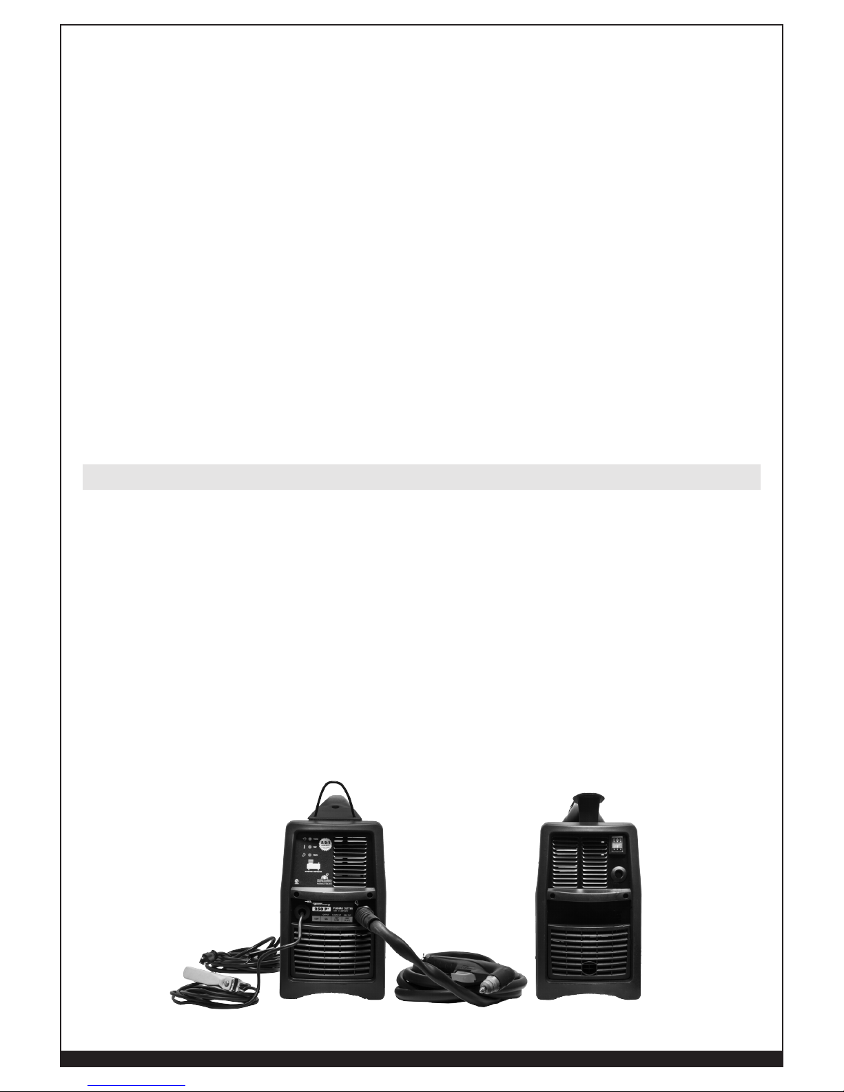
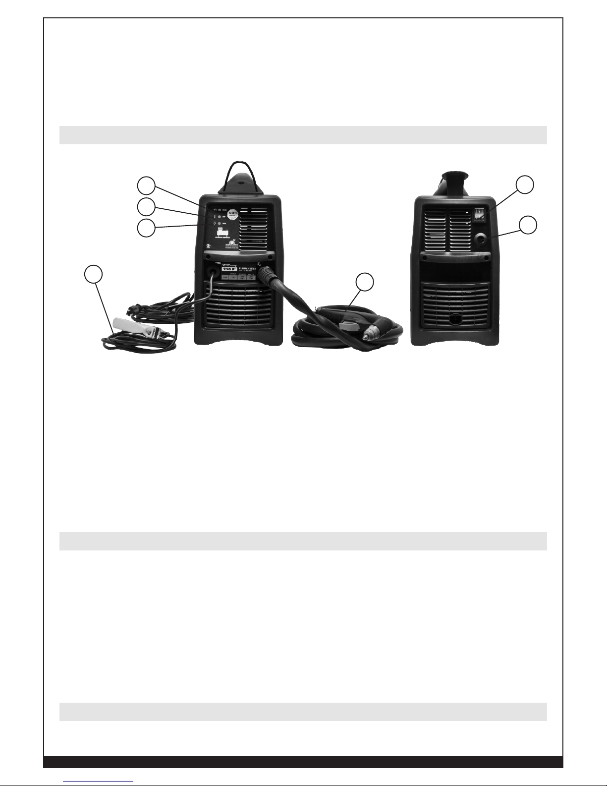
FRONT VIEW OF 250P+ PLASMA SYSTEM REAR VIEW OF 250P+ PLASMA SYSTEM
Plasma System Set-Up
14
WWW.FORNEYIND.COM
POWER SOURCE HANDLING & POSITIONING
• Locate your Forney 250P+ Plasma System near a 120VAC power receptacle.
• Should an extension cord be required, Forney suggests a 120V, 1-Phase extension cord with
a 10 AWG gauge size up to a maximum of 50 feet in length.
• Choose location verifying that there is a good air flow and no dust, smoke or gas is present.
• Place the unit on a flat and stable surface.
• Make sure that obstacles do not prevent the cooling air flow out of front and rear openings
of the machine.
• Arrange an open space of at least 15 feet (5m) around the machine.
• In the case the machine has to be moved, always disconnect the plug from the outlet and
gather the cables so as not to damage them.
REQUIREMENTS FOR GROUNDING
• To ensure personal safety, proper operation, and to reduce electromagnetic interference
(EMI), the Forney 250P+ must be properly grounded.
• The power supply must be grounded through the power cord according to national and local
electrical standards.
• Single-phase service must be of the 3-wire type with a green or green/yellow wire for the
protective earth ground. Do not use 2-wire service.
AIR/GAS SUPPLY
• Your Forney 250P+ Plasma System includes a built-in piston air compressor; therefore, you
have no need for a shop air source or compressed gas cylinders to operate your system
successfully.
USE ONLY TORCHES SPECIFIED IN THIS INSTRUCTIONS MANUAL.
CAUTION! Disconnect power source before assembly / disassembly of the torch.
BEFORE STARTING THE CUTTING OPERATIONS VERIFY THAT THE PARTS ARE
PROPERLY ASSEMBLED BY INSPECTING THE HEAD OF THE TORCH AS SHOWN
BELOW.
INSTANT-ON TORCHES, PLASMA ARC CAN CAUSE INJURY AND BURNS.
CAUTION! The plasma arc comes on immediately when the torch trigger is activated. Make
sure the power is off and the machine disconnected before changing consumables.
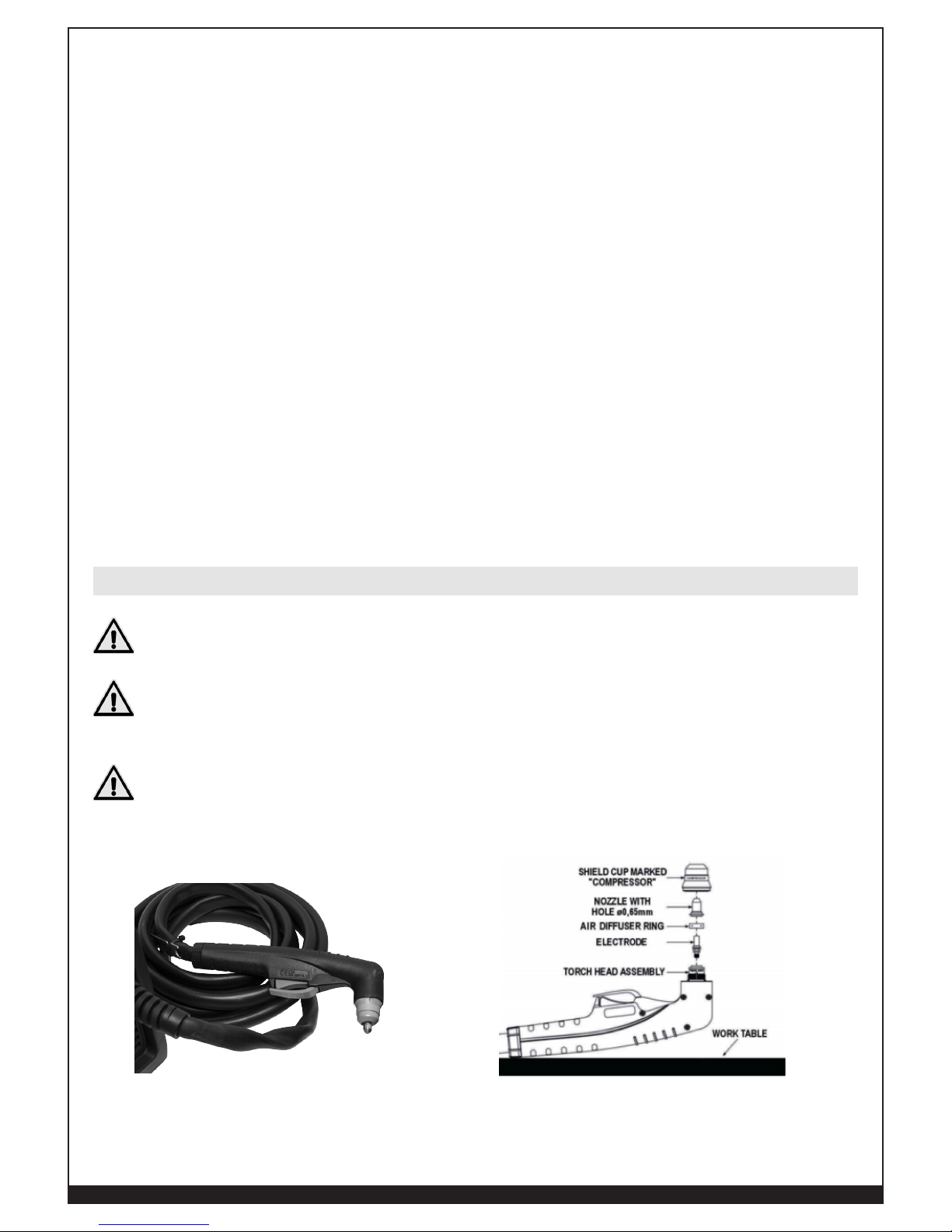
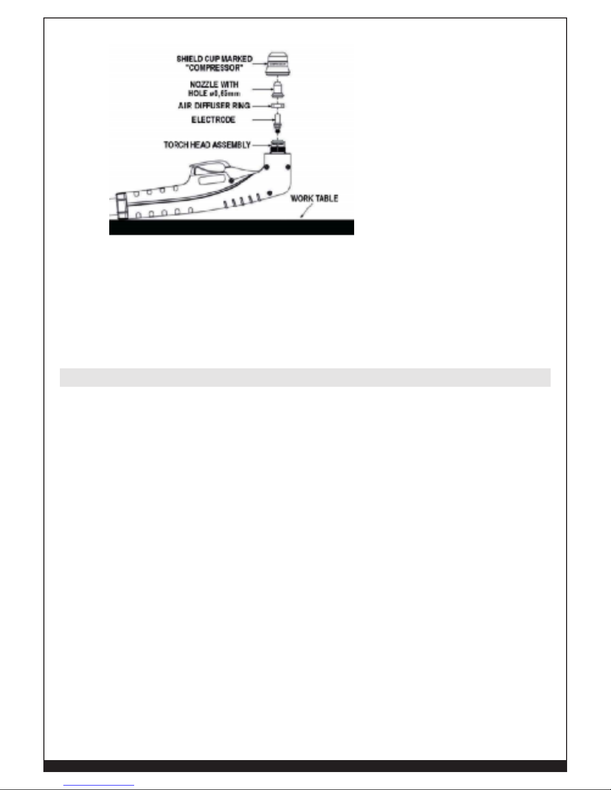
PROPERLY ASSEMBLED PLASMA TORCH PROPER ASSEMBLY SEQUENCE OF PLASMA CONSUMABLES
In the event that your plasma torch consumable parts are not already assembled, use the
following procedure:
Torch Assembly (if required)
15
WWW.FORNEYIND.COM
1. Position the torch with the shield cup facing upward to prevent these parts from falling out.
2. Install the electrode, air diffuser ring, and nozzle.
3. Hand-tighten the shield cup until it is seated on the torch head. If resistance is felt when
installing the cup, check the threads before proceeding.
4. Included in the parts bag with your machine are 1-each of an electrode and nozzle for future
use in replacing worn parts. See Torch Maintenance for replacement procedure.
Function & Control
1. ON/OFF Switch – In the ON position the machine is ready for normal operation. All system
control circuits are activated. OFF position deactivates control circuits.
2. Green LED– It blinks for a few seconds to show that capacitors are being charged and that
the unit is getting ready for operation. It turns ON when input voltage is applied within
normal range – blinks slowly when input voltage goes above 135VAC, or below 85VAC.
3. Yellow LED– Turns ON when the thermal protection is activated.
4. Red LED–Turns ON when torch is triggered. Blinks quickly during pre-flow prior to pilot arc
ignition. Blinks slowly if cutting arcs not initiated after 3-second pilot arc ignition.
5. Work cable
6. Plasma Torch
7. Input power cable
Work Clamp Attachment
Connect the ground cable clamp to the work-piece to be cut or to the metallic workbench. Take
following precautions:
• Verify that there is a good electrical contact particularly if insulated or oxidized coated sheets
are cut.
• Make ground connections as close as possible to the cutting area to reduce exposure electric
and magnetic fields (EMF).
• The use of the metallic structures which are not part of the work-piece, such as the return
cable of the cutting current, may endanger the safety system and give poor cutting results.
• Do not make a ground connection on the piece which has to be removed.
• The work clamp must be attached to the work-piece while cutting.
Connect Input Power Cord
Plug in the Forney 250P+ power cord to a proper 120V receptacle.
1
7
6
5
4
3
2

16
WWW.FORNEYIND.COM
Power On the System
Set the ON/OFF switch which is on the back of the power source to the On (I) position.
Cutting Operation
BEFORE OPERATING THE SYSTEM
CAUTION! Disconnect power source before disassembly of the torch. Check and follow instructions
including safety precautions presented in this operating manual.
Parts of the Torch
Check the torch for proper parts assembly order and installation (refer to Section called Torch
Consumable Parts Selection). NOTE: The power supply will not operate unless the torch shield cup is
fully seated against the PIP (Parts in Place) pins in the torch head.
Input Power
• Check the power source for proper input voltage.
• Make sure the power source meets circuit protection and wiring requirements.
• Plug unit in and close main disconnect switch to supply primary power to the system.
Work Clamp, Ground Cable
Check for a solid ground cable connection to the work piece.
Automatic Purge System
• Place the ON/OFF switch to the ON position. The ON light will flicker momentarily as the
system powers up and then stays on.
• Activate the torch trigger to initiate gas purge (pre-flow) to remove any condensation that
may have accumulated in the torch and leads while the system was shut down.
• When the gas purge is complete, pilot arc will be initiated.
• If during cutting there is still condensation exiting from the torch, stop cutting and turn unit
off. Wait for torch cooling to remove the shield cup. Dry the shield cup inside with dry air.
Checking Air Quality
• To check air quality, deactivate the torch (post-flow) and place welding filter lens in front of
the torch. Any oil or moisture in the air will be visible on the lens.
• DO NOT initiate pilot arc while checking air quality.
The Forney 250P+ plasma system is a highly portable, 12-amp, 120V/15A hand-held plasma cutting
system with built-in air compressor appropriate for a wide-range of cutting applications.
The Forney 250P+ plasma system includes one complete set of consumables needed for cutting (Shield
Cup, Air Diffuser Ring, Electrode and Nozzle), torch assembly, torch lead, ground cable with ground
clamp, plasma inverter power source with a 120V/15A (NEMA 5-15P) plug.
Operation
Description

17
WWW.FORNEYIND.COM
Additional consumables and accessories can be ordered for any Forney Authorized Dealer. See
Maintenance and Parts section of this manual for additional information.
Weight: 35 Lbs. (15.88Kg)
Rated Output Voltage 84.8V
Duty Cycle, 120 VAC 25% @ 12 A
Thermal Overload Protection 35% Duty Cycle @ 104F degrees (40C degrees)
Input Voltage 120 VAC / 20 A, 60Hz
Phase Single
Circuit 15 Amps, with time-delay fuses (20A) or circuit breakers
Generator Requirements:
Engine Drive
Output Current
Performance
2,500 W
20 Amps
Full Arc Stretch
Extension Cord Requirements:
Input Voltage
Phase
Cord Gauge Size
Length
120 VAC
Single Phase
10 AWG
33ft (10m) Suggested, 50ft (15m) Maximum
On the bottom of the Plasma System there is a plate that includes all of the operating specifications of
your Forney 250P+ Plasma System. Including the serial number of the product.
The duty cycle is the amount of time, in minutes, that a plasma arc can remain on within a 10-minute
period when operated at an ambient temperature of 104 degrees F (40 degrees C).
• At 12 A, the arc can remain on for 2.5 minutes out of 10 minutes without causing the unit to
overheat (25% duty-cycle).
If the power supply overheats because its duty cycle is exceeded, the yellow temperature LED will
illuminate, the arc will shut off and the cooling fan will continue to run. To resume cutting, wait for the
yellow temperature LED to extinguish. NOTE: Exceeding duty cycle can damage the system and void
warranty
Power Source Rating & Specifications
Performance Data Plate
Duty Cycling & Overheating
18
WWW.FORNEYIND.COM
Model: Plasma Torch
• Air-cooled torch for plasma arc cutting (PAC)
• Parts-In-Place (PIP) safety features require all parts to be in place prior to operation,
• Safety trigger guard
• 35% Duty Cycle
• Cutting Capacity, see below
In the event that pilot arc is not transferred between the plasma torch (electrode) and the work piece
within three seconds of pilot arc start, the cycle automatically stops (pilot arc stops) and the post flow air
continues to run cooling the torch.
Steel
Stainless
Steel
Aluminum Galvanized Brass Copper
1/4”
1/8” 1/16” 1/16” 1/16” 1/16” 1/16”
RECOMMENDED CAPACITY SEVERANCE CAPACITY
• Optimal system performance
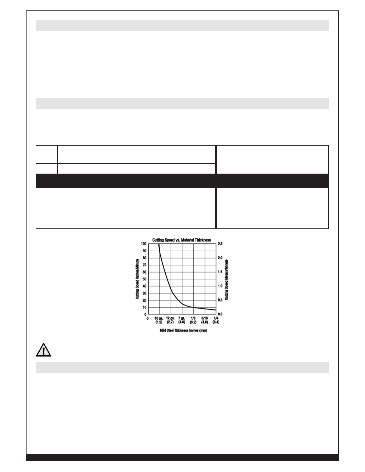
• Cut speeds of at least 10 inches per minute IPM
• Ideal operating range for excellent cut quality
• Rated with new consumables.
• Top end of system capabilities
• Intended for occasional severance
requirements; where a lower degree of
cut quality is acceptable
• Slower cut speeds
DISCONNECT PRIMARY POWER AT THE SOURCE AND WAIT FOR THE TORCH
TO COOL BEFORE DISASSEMBLING THE TORCH OR TORCH LEADS.
PILOT ARC: STARTING THE ARC
Upon squeezing the trigger there is a 1.5 second delay to purge the torch air system. After 1.5 seconds
the pilot arc ignites, immediately transfer the arc to the work piece and begin the cut. If you fail to
transfer the arc within three seconds the pilot arc stop and it will be necessary to release and then
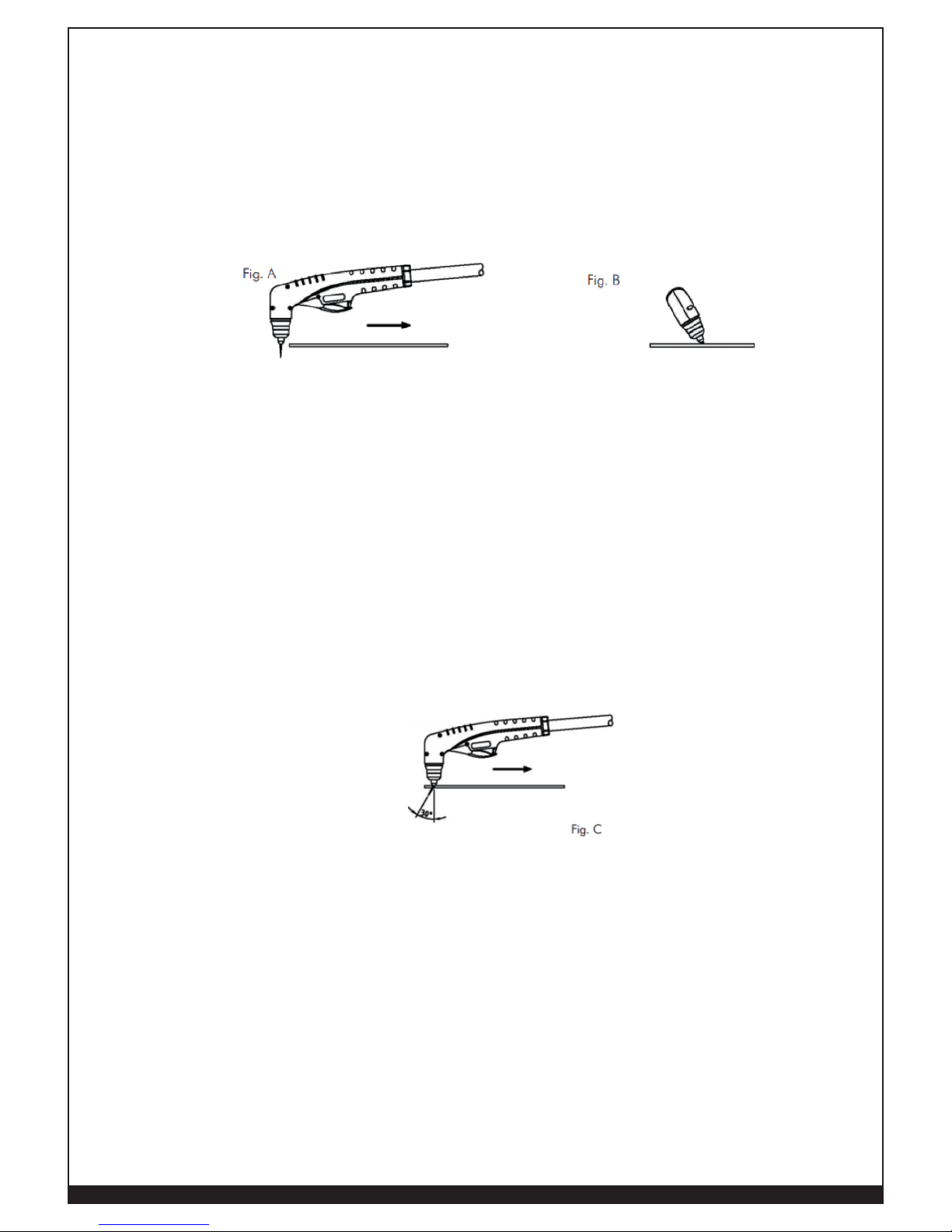
squeeze the trigger again to restart the sequence. Fig. A shows a pilot arc prior to transferring the arc
to the work piece. NOTE: Repeated pilot arc starts without cutting is not recommended and will shorten
the life of consumable torch parts. Always keep in mind that the Pilot arc is designed to transfer the arc
to the work piece and not for numerous starts without cutting.
Torch Ratings & Specifications
Cutting Capacity
Cutting
19
WWW.FORNEYIND.COM
CUTTING WITH A HAND TORCH
• The torch can be comfortably held in one hand or steadied with two hands. Choose the
technique that feels most comfortable and allows good control and movement. Position the
index finger or thumb to press the control switch on the torch handle.
• With the torch in starting position, press the control switch. After an initial gas purge (preair), the pilot arc will come on and remain on for 3 seconds until the cutting arc starts.
• For edge starts, hold the torch perpendicular to the work piece with the front of the tip on the
edge of the work piece at the point where the cut is to start. Fig. A.
• For drag cuts keep the torch in contact with the work piece.
• For standoff cutting, hold the torch 5/64” to 1/8” (2-3mm) from the work.
• For straight-line cuts, use a straight-edge as guide for your torch.
• For circle cuts, use a template or circle cutting attachment guide to get the radius you desire.
• Once on, the main arc remains on as long as the control switch is held down, unless the
torch is withdrawn from the work or torch motion is too slow. Keep moving while cutting. Cut
at a steady speed without pausing. Maintain the cutting speed so that the arc lag is about
30° behind the travel direction. Fig. C
• Adjust the torch speed so sparks go thru the metal and out the bottom of the cut.
• Pause at the edge (end of your cut) until the arc has cut completely through the work piece.
If sparks are being blown upward and back at the torch head, your torch travel speed is too
fast, decrease your travel speed.
• To shut off the torch simply release the control switch. When the switch is released a postflow will occur. If the torch trigger is pressed during the post-flow, the pilot arc will restart.
• Refer to the Troubleshooting section of this operating manual should the torch or system not
operate as expected.
NOTE: If the cutting arc is interrupted, and the torch trigger is still pressed, the pilot arc comes
back on automatically after 3 seconds.
NOTE: If sparks are being blown upward and back at the torch head, your torch travel speed is
too fast, decrease your travel speed.
PIERCING WITH A HAND TORCH
NOTE: If necessary to make a cut on a metal sheet which is thicker than the maximum piercing capacity
(without an edge start) make a hole 1/4” (6.35mm) at least using an electric drill to start cutting.
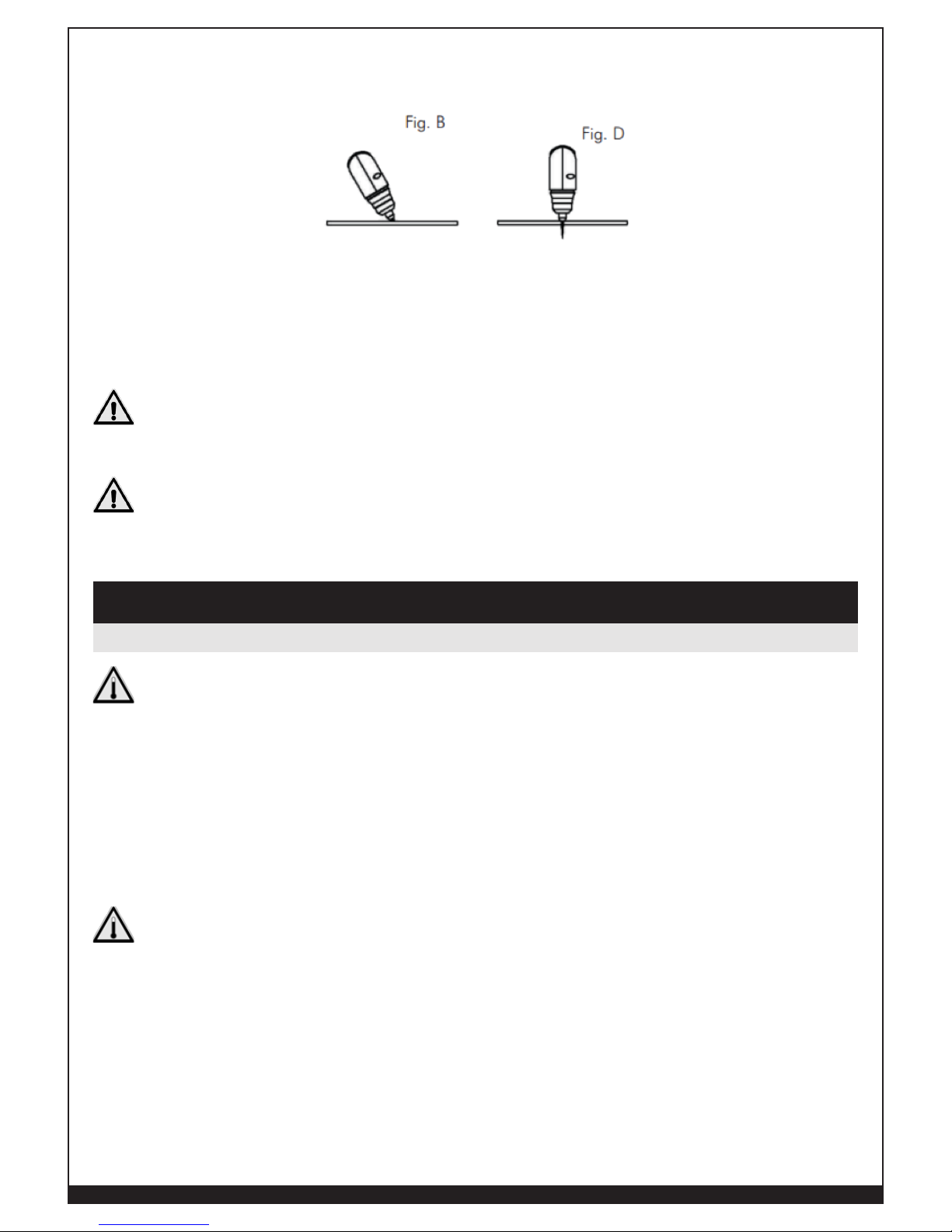
• When piercing with a hand torch, tip the torch slightly so that blowback particles blow away
from the torch tip (and operator) rather than directly back into it. Fig. B
• Complete the pierce off the cutting line and then continue the cut onto the line. Hold the torch
perpendicular to the work piece after the pierce is complete. Fig. D
• Clean spatter and scale from the shield cup and the tip as soon as possible. Spraying or
dipping the shield cup in anti-spatter compound will minimize the amount of scale which
adheres to it.
20
WWW.FORNEYIND.COM
• Refer to the Troubleshooting section of this operating manual should the torch or system not
operate as expected.
IMPORTANT! Frequently review the Important Safety Precautions at the front of this Manual.
DISCONNECT PRIMARY POWER AT THE SOURCE AND WAIT FOR THE TORCH TO
COOL BEFORE DISASSEMBLING THE TORCH OR TORCH LEADS.
CAUTION! Be sure the operator is equipped with proper gloves, clothing, and eye & ear
protection. Make sure no part of the operator’s body comes into contact with the work piece
while the torch is activated.
CAUTION! Sparks from the cutting process can cause damage to coated, painted, and other
surfaces such as glass, plastic and metal.
NOTE: Handle torch leads with care and protect them from damage.
DISCONNECT PRIMARY POWER AT THE SOURCE AND WAIT FOR THE TORCH
TO COOL BEFORE DISASSEMBLING THE TORCH OR TORCH LEADS OR
PERFORMING MAINTENANCE.
CAUTION! Maintenance can only be carried out on the unit if the person in charge of this
operation has the necessary technical knowledge and the correct tools. If this is not the case,
contact your nearest service center.
CAUTION! Never access inside the machine (panel removal) or touch the torch (disassembly)
without having disconnected power plug.
ANY INSPECTION PERFORMED UNDER VOLTAGE INSIDE THE MACHINE OR
INSIDE THE TORCH MAY CAUSE SEVERE ELECTRIC SHOCKS CAUSED BY DIRECT
CONTACT WITH PARTS UNDER VOLTAGE.
CAUTION! Use only dry compressed air for cleaning. Do not point the jet of air at the
electronic circuits contained within this system.
The Forney 250P+ Plasma System is a tool that must routinely be maintenanced in order to keep the
system in optimal working condition and to provide long-term value for your investment. Failure
to maintain the system, its consumables and the working environment will decrease the systems
performance and produce results below optimal performance levels.
Maintenance & Servicing
General Maintenance
21
WWW.FORNEYIND.COM
FREQUENCY PERIODIC MAINTENANCE TO BE PERFORMED
Each Use • Check the indicator lights and correct any fault
conditions.
• Check & clean shield cup, nozzle, air diffuser
ring and electrode for proper installation, wear,
damage (burns, distortions or cracks), dirt, debris
and restricted holes.
Weekly • Check shield cup shut down system.
3 Months • Replace any cracked or damaged parts.
• Check the torch trigger for damage.
• Check torch body for wear, exposed wires or
damage, replace as required.
• Check outer covering of work clamp lead for wear,
repair or replace as required.
• Check the power cord for wear or damage,
replace if damaged.
6 Months • Check compressor, clean with dry cloth.
• Blow out or vacuum inside.
CAUTION! Plasma torch consumable parts should be
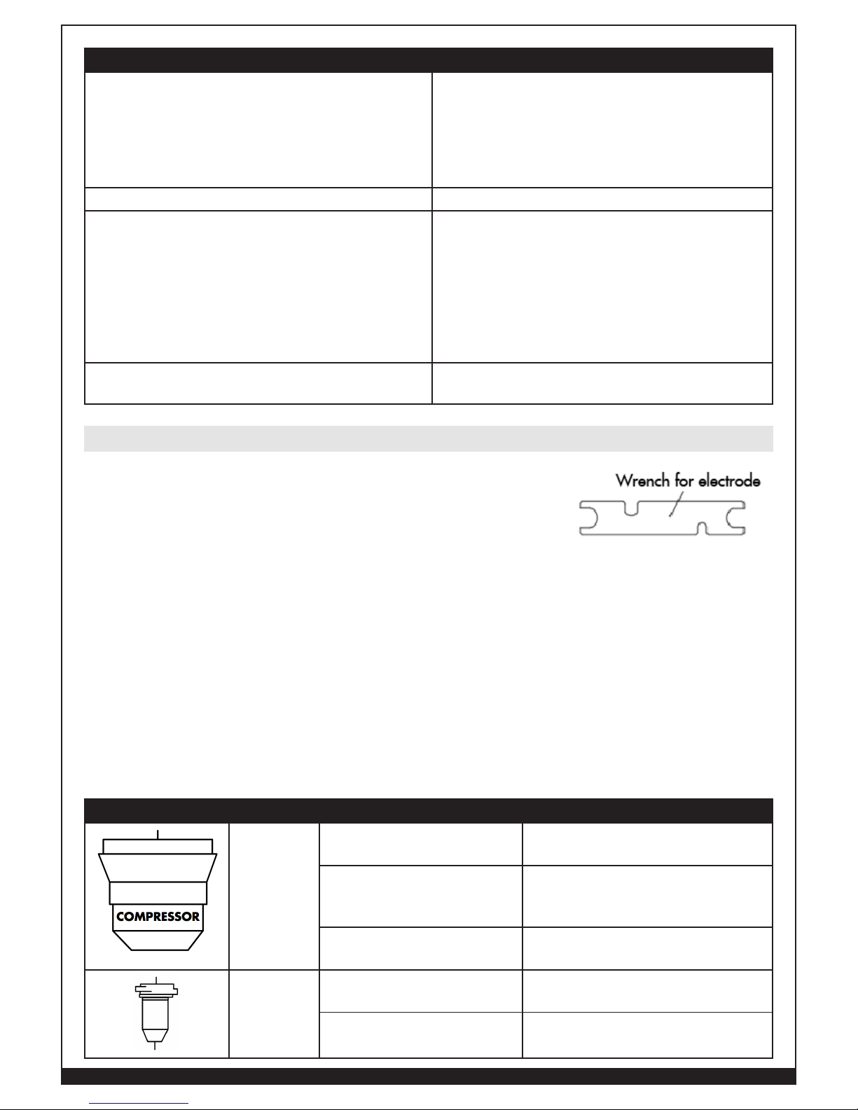
hand-tightened. A wrench is provided for electrode removal in
the event you need extra leverage in removal.
CAUTION! Inspect shield cup, nozzle, air diffuser and electrode for wear and debris before
cutting or whenever cutting speed has been significantly reduced.
CAUTION! Use only dry compressed air for cleaning. Do not point the jet of air at the
electronic circuits contained within this system.
CAUTION! Do not operate torch without a nozzle or electrode in place. Be sure to use
genuine Forney parts.
NOTE: It is recommended that the electrode and nozzle should be replaced at the same time to insure
even wear and optimal performance.
PART INSPECT ACTION
Shield Cup
The center hole for roundness.
Replace the shield cup if the hole is
no longer round.
The gap between the
shield cup and nozzle for
accumulated debris.
Remove the shield cup and clean
any debris away, replace if
damaged or un-cleanable.
Examine for cracks, burnthrough or chips.
Replace shield cup if cracked,
burned-through or chipped.
Nozzle
(Tip)
Center hole should be
round.
Replace if the center hole is no longer round, out-of-round.
Oxidized exterior. Can be cleaned with an abrasive
cloth, use no solvents.
Consumable Maintenance
22
WWW.FORNEYIND.COM
PART INSPECT ACTION
Air Diffuser
Ring
Verify there are no burns or
cracks or that airflow holes
are not obstructed.
If damaged, replace.
Electrode
The center surface for wear
and verify pit depth.
Replace electrode when crater settling on emitting surface is about
1/16” (2mm).
Torch Head
Check surface for damage,
wear, debris.
Clean if debris is present without
use of solvents.
Replace torch if head is cracked or
worn.
Torch Body
Handle &
Cable
These parts usually need no
particular maintenance with
the exception of a periodic
inspection and cleaning.
Clean if debris is present without
use of solvents
Replace torch if cracked or worn.
DO NOT touch torch and cable
with warm or hot parts.
DO NOT strain the cable.
DO NOT move the cable on sharp
edges or abrasive surfaces.
Gather the cable in regular coils if it
is too long.
DO NOT step on the cable.
Work
Clamp &
Cable
These parts usually need no
particular maintenance with
the exception of a periodic
inspection and cleaning.
Follow same actions as Torch Body,
Handle and Cable
Water Filter
Check for moisture Drain if needed.
During cutting operations performance faults may arise which are not caused by equipment
malfunctioning but by other operational faults such as:
Most common plasma cutting faults:
1. The cut speed is too fast.
2. The consumables are worn.
3. The metal being cut is too thick.
4. The work clamp is not properly attached to the work piece.
Troubleshooting

23
WWW.FORNEYIND.COM
The following table represents the most common problems associated with using the Forney 250P+
plasma system and an explanation on how to resolve them.
If you are unable to fix the problem by following the basic troubleshooting guide or if you need further
assistance:
1. Call your Forney Authorized Dealer;
2. Call Forney Customer Service.
TROUBLE EXPERIENCED POSSIBLE REASONS RECOMMENDED SOLUTION
GREEN LED OFF, Fan not
operating.
No Input Power Connect system to proper input power source.
Verify that the power is on the main power panel
or at the disconnect-power switch box.
Insure power switch (rear) is in the On position
GREEN LED ON, YELLOW
Over-temperature LED
ON.
Unit is overheated. Allow unit to cool with internal fan running,
once cool reduce arc cutting time to below duty
cycle rating of the system.
Air flow obstructed Check torch consumables for proper installation.
Examine the consumables for wear, debris, obstructed holes and replace worn parts with new
Forney consumable parts
Inspect air compressor for proper operation.
GREEN LED ON, YELLOW
Over-temperature LED
OFF, no air flow when
torch switch pressed.
Shield cup not properly
installed
Check that torch consumables are properly
installed.
Faulty torch switch or
parts assembly in torch
holder
Replace torch.
Faulty main PC Board Trained technical service required.
GREEN LED ON, YELLOW
Over-temperature LED
OFF. Air flows, Pilot arc
does not start.
Faulty torch parts Replace torch.
Faulty main PC Board Trained technical service required.
Torch has pilot arc but
does not cut.
Work lead not connected
Properly connect the work clamp to the work
piece.
AC input power too
low
Insure system has proper input power source
If used, eliminate or reduce length of extension
cord.
Faulty main PC Board Trained technical service required.
The arc does not transfer
to the work piece.
Insufficient work clamp
contact with the work
piece
Clean the area where the work clamp attaches
to the work piece to insure a good metal to
metal connection.
Inspect the work clamp and its lead for damage,
repair or replace as necessary.
Torch may be too far
away from the work
piece.
Move torch closer to the work piece and fire the
torch again.

24
WWW.FORNEYIND.COM
TROUBLE EXPERIENCED POSSIBLE REASONS RECOMMENDED SOLUTION
Poor cut quality
Improper use of torch Review operating instructions
Torch parts are worn
out
Examine the consumables for wear and replace
worn parts with new Forney consumable parts
Moisture coming out of
the torch
Moisture forms from the
air compressor inside
the plasma system
It is normal to see some moisture coming from
the torch due to the internal air compressor.
Sparks are being blown
upward and back at the
torch head
Too high cutting speed Decrease your torch travel speed
Work piece is too thick Choose thinner work piece material within the
operational limits of the system.
Insufficient Penetration
Too high cutting speed Decrease your torch travel speed
Torch is too tilted Insure that torch is perpendicular to the work
piece
Work piece is too thick Choose thinner work piece material within the
operational limits of the system.
Cutting current too low Insure system has proper input power source
If used, eliminate or reduce length of extension
cord.
Torch parts are worn
out
Examine the consumables for wear and replace
worn parts with new Forney consumable parts
Non-genuine
Manufacturer’s parts
Use only genuine Forney consumables for
optimum performance
Interruption of the
Cutting Arc, but re-ignites
when triggered again
Cutting speed too slow Increase your torch travel speed
Excessive distance
between torch and
work piece
Decrease the distance between the torch and the
work piece
AC line too low reduce output current
Insure system has proper input power source
If used, eliminate or reduce length of extension
cord.
Torch parts are worn
out
Examine the consumables for wear and replace
worn parts with new Forney consumable parts
Non-genuine
Manufacturer’s parts
Use only genuine Forney consumables for
optimum performance
Work cable is
disconnected
Securely clamp the work cable to the material
being cut, as close to the work area as possible.

25
WWW.FORNEYIND.COM
TROUBLE EXPERIENCED POSSIBLE REASONS RECOMMENDED SOLUTION
Excessive Dross
Too slow cutting speed
(bottom dross)
Increase your torch travel speed
Too fast cutting speed
(top dross)
Decrease your torch travel speed
Excessive distance between torch and workpiece
Decrease the distance between the torch and the
work piece
Cutting current too low Insure system has proper input power source
If used, eliminate or reduce length of extension
cord.
Torch parts are worn
out
Examine the consumables for wear and replace
worn parts with new Forney consumable parts
Non-genuine Manufacturer’s parts
Use only genuine Forney consumables for optimum performance
Tilted Cutting Angle
(not perpendicular)
Torch position not correct
Insure that torch is perpendicular to the work
piece
Check torch consumables for proper installation.
Asymmetric wear of
nozzle hole and/or
wrong assemblage of
the torch parts
Examine the consumables for wear and replace
worn parts with new Forney consumable parts
Excessive Wear of the
Nozzle
or Electrode
Air pressure too low Inspect air compressor for proper operation.
Exceeding system
capability (material too
thick)
Choose thinner work piece material within the
operational limits of the system.
Contaminated air
(humidity-oil)
Inspect air compressor for proper operation.
Excessive pilot arc ignitions in the air
Discontinue false starts without b eing in contact
with the work piece.
Improperly assembled
torch
Check torch consumables for proper installation.
Torch tip contacting
work piece
Follow proper procedures for cutting or piercing.
Damaged or loose
torch head components
Check torch consumables for proper installation.
If damaged, replace torch.
Non-genuine manufacturer’s parts
Use only genuine Forney consumables for optimum performance
Overheating
Exceeding Duty Cycle
of the plasma system
Allow unit to cool with internal fan running,
once cool reduce arc cutting time to below duty
cycle rating of the system.
26
WWW.FORNEYIND.COM
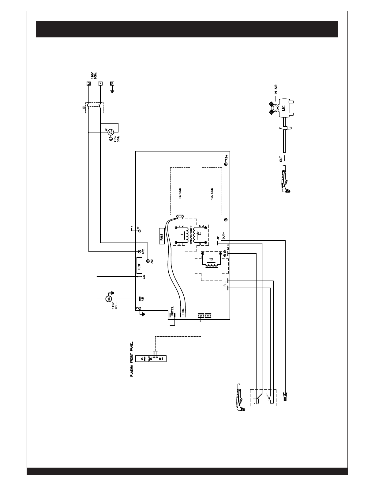
Wiring Diagram

27
WWW.FORNEYIND.COM
Parts
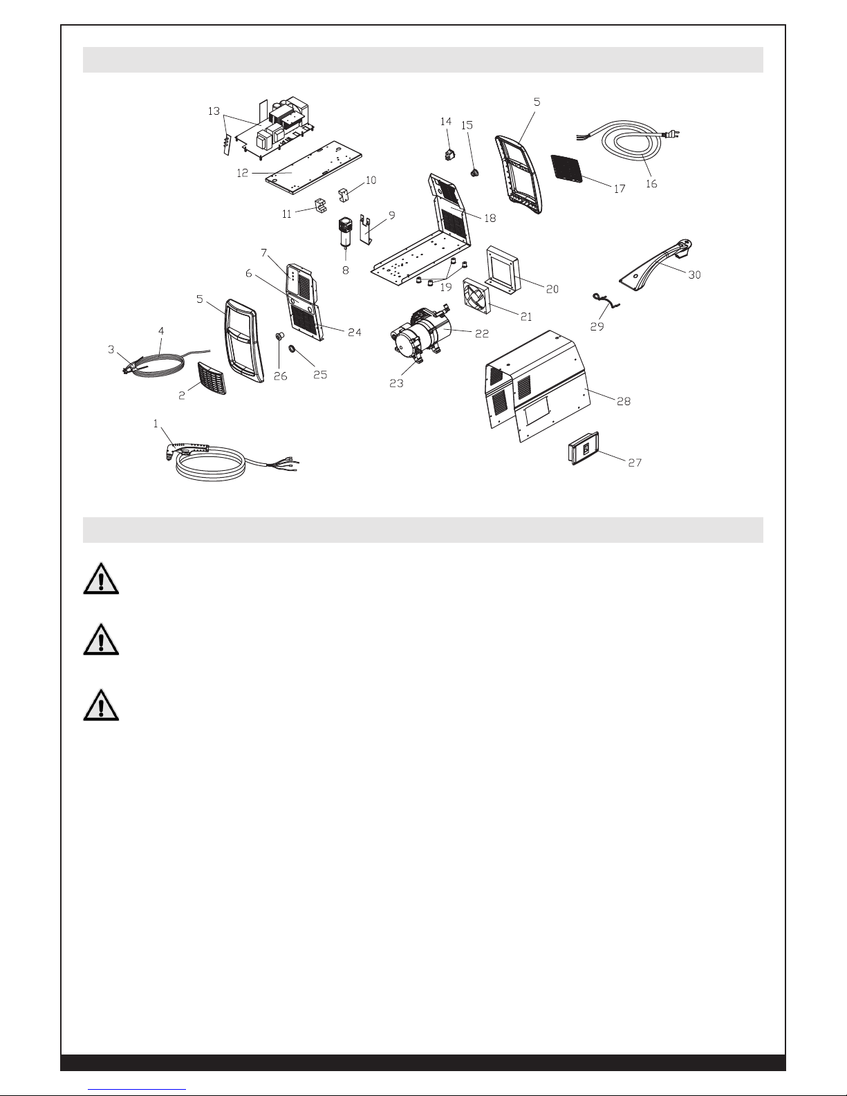
REF. # PART # ITEM DESCRIPTION QTY
01 23010112 PLASMA TORCH PT-40C 15" FIX CONNECTION 1
02 85409 PLASTIC AIR-VENT 1
03 84964 EARTH CLAMP 200A 1 PC PACK 1
04 43210219 GROUND CABLE 6MM2 - 15" 1
05 21690505 FRAME FOR PLASMA COMBI 1
06 77650452 PLASMA 250P+ CUTTING INFO LABEL 1
07 77650451 FRONT PANEL LABEL 1
08 22905074 MOISTURE DRAIN 1
09 33640285 METAL SUPPORT FOR AIR FILTER 1
10 21690245 TORCH PRESSURE COVER 1
11 21690513 TORCH BLOCK 1
12 33620308 DIVIDING PANEL 1
13 85405 MAIN PC BOARD PLASMA FIX 1
14 85407 BIPOLAR BLACK SWITCH W/PROTECTION 1
15 85209 CABLE CLAMP D.10 + SCREW 1
16 20220182 INPUT CABLE SJT3XAWG14 15' 120V 5-15A 1
17 85413 LOUVRE FOR PLASMA 1
18 33700426 9005 LOWER PANEL 1
19 85412 RUBBER FOOT D.20 L=25 1
20 33640301 METAL SUPPORT FOR FAN 1
21 26089008 FAN 115/230VAC 120X120X38 1
22 85411 COMPRESSOR 60HZ 110V 1
23 21610028 RUBBER FOOT 1
24 05000296 FRONT PANEL 1
25 21605023K RUBBER GROMMET HOLE D.24 20X32 5 PC PACK 5
26 85208 CABLE CLAMP FOR CABLE DIAM.6+ SCREW 1
27 04600350 BOX FOR CONSUMABLES 1
28 05000298 COVER 1
29 33740579 9005 TORCH WRAPPER 1
30 21600067 HANDLE FOR TORCH WRAPPER 1
Unit Parts List
28
WWW.FORNEYIND.COM
Unit Parts Breakdown
Torch Consumable Parts Selection & Replacement
DISCONNECT PRIMARY POWER AT THE SOURCE AND WAIT FOR THE TORCH
TO COOL BEFORE DISASSEMBLING THE TORCH OR TORCH LEADS.
USE ONLY TORCHES AND CONSUMABLES SPECIFIED IN THIS OPERATING
MANUAL.
IT IS EXTREMELY IMPORTANT THAT YOU READ CAREFULLY THESE STRUCTIONS
BEFORE CHOOSING THE CONSUMABLES FOR YOU TORCH. THIS WILL
PREVENT DAMAGES TO YOUR TORCH AND PLASMA SYSTEM.
Plasma torch consumables through the course of normal use will wear and need to be replaced
periodically. Before using the plasma system, you should check your parts for wear and replace if
necessary.
The PIP (Parts-In-Place) design of the torch requires that consumables be installed correctly in order for
the torch to operate. To change the torch consumable parts use the following procedure:
1. Position the torch with the shield cup facing upward to prevent these parts from falling out
when the cup is removed.
29
WWW.FORNEYIND.COM
CAUTION! Hand-tighten the shielding cup, use no tools or you risk damaging
your torch and consumables.
2. Unscrew and remove the shield cup from the Torch Head Assembly.
3. Remove the tip, gas distributor, and electrode.
4. Install the electrode, gas distributor, and tip.
5. Hand-tighten the shield cup until it is seated on the torch head. If resistance is felt when
installing the cup, check the threads before proceeding.
Torch Parts List
23010083 PLASMA TORCH WITH 13’ LEAD
01 23015183 PLASMA TORCH BODY 1
02 23015187 ELECTRODE 1
03 23015179 AIR DISTRIBUTION RING 1
04 23015189 TIP ø0,65 / .025 1
05 23015182 SHIELD CUP 1
06 23015193 WRENCH FOR ELECTRODE 1
07 23015184 COMPLETE HANDLE 1
08 23015195 CABLE ASSEMBLY 1
 Loading...