

Forney 235, 235FI Operating Manual

235 AC/DC ARC WELDER
OPERATING MANUAL
FEATURES:
• Dinse style connectors allow for easy cable
replacement and polarity change
• Power cable, ground cable, and electrode holder
are all 15’ providing a large working envelope
• Welds up to 1/2” AC / 3/8” DC metal
SPECIFICATIONS:
• Power: 235 Amp AC @ 20% Duty Cycle
• Weight: 116 Lbs. (52.63 Kg)
• Max. OCV: 72 VAC / 63 VDC
• Main Voltage: 230V (60Hz)/48.5A
• Duty Cycle: 150A @ 50% AC / 135A @ 35% DC
• Output Range: 45A - 235A AC / 45A - 185A DC
IDEAL FOR:
Maintenance and Sheet Metal Fabrication, Agriculture,
Automotive, Contractors, Repair, Hobbist, and More...
INCLUDES:
Input power cable, Ground cable and clamp, Electrode
holder and cable
*Wheel and handle kit purchased separately (CAT #329)
CAT# 314
ENGLISH
REV 10.27.15

2
WWW.FORNEYIND.COM
STOP!
PLEASE DO NOT
RETURN TO THE STORE
If you have questions or problems with your new welder, please
call customer service at 1-800-521-6038 Monday through
Friday from 7 a.m. - 5 p.m. (MST) or at
www.forneyind.com/customer_service.
Please take time to register your product at
www.forneyind.com/customer_service/register_your_product/
Thank you, enjoy your new welder.

3
WWW.FORNEYIND.COM
Forney Promise
We are committed to your success regardless of location, size or
needs. We understand it is your goal to get the job done right,
and we are ready to help you do just that.
President's Message
We market the highest quality tools, equipment and accessories
for the do-it-yourselfer and professional. Our passion and
dedication in bringing new products to the industrial and retail
market, combined with our personal service, is unmatched in our
industry. Our ability to listen to our customers’ needs enables us to
create solutions to their problems.
Our dedication to the highest quality customer service within our
corporate headquarters and the service provided in the field is
unequaled. We are committed to creating the best solutions to our
customer’s needs. Above all, our employees will provide the same
respect and caring attitude within the organization as they are
expected to share with every Forney customer. Our goal will be to
exceed our customers’ expectations through empowered people,
guided by shared values and commitments.
We work hard so our customers trust us because of our integrity,
teamwork and innovation of Forney products, and Forney’s
80 years of unmatched product quality and an unwavering
commitment to our customers.
When our customers succeed we succeed.
STEVEN G. ANDERSON, President & CEO
Copyright© 2014 Forney Industries,
Inc. All rights reserved. Unauthorized
reproduction and/or distribution is
subject to US copyright laws.
U.S. Warehouses:
- Fort Collins, CO
- Tipp City, OH
FIVE WAYS TO ORDER
Web: www.forneyind.com
Phone: 80 0-521-6038
Fax: 970-498-9505
Mail: Forney Industries
2057 Vermont Drive
Fort Collins, CO 80525
Email: sales@forneyind.com

4
WWW.FORNEYIND.COM
Forney 5/3/1 Limited Warranty
Effective August 1, 2009
1) Limited Warranty: Subject to the terms and conditions below, Forney Industris, Inc., Fort Collins,
Colorado, warrants to its original retail purchaser that the new Forney equipment sold after the effective date
of this limited warranty is free of defects in material and workmanship at the time it is shipped by Forney. This
is in lieu of all other warranties, expressed or implied.
2) Notifications: Please call 1-800-521-6038 with your warranty questions. You can also visit:
www.forneyind.com for additional information about your new welder or plasma system.
3) Length of Warranty: Within the warranty periods listed below, Forney will repair or replace any
warranted parts or components that fail due to defects in material or workmanship. Warranty is effective
from the date of original retail purchase. Warranty duration is as follows.
A) 5 years: Original main power rectifiers only to include SCRs, diodes and discrete rectifier modules,
transformers, stabilizers, and reactors.
B) 3 years: Drive Systems, PC Boards, Motors, and Switches and Controls
C) 1 year: MIG guns, relays, contactors, and regulators, plasma cutting torches, and accessories.
D) 90 days: Replacement parts. Does not include labor.
4) Forney’s limited warranty shall not apply to consumables such as contact tips, cutting nozzles, felt wire
cleaner, drive rollers, gas diffusers, plasma torch tips and electrodes, weld cables, tips and parts that fail
due to normal wear. In addition, this warranty does not extend to any damage caused by the untimely
replacement or maintenance of any of the previously listed consumable parts.
5) Warrantor:
Forney Industries
2057 Vermont Drive
Fort Collins, CO 80525
1-800-521-6038
www.forneyind.com
6) Purchaser / Warranty: The original purchaser of the Forney Industries product. The warranty is
not transferable. Forney Industries products are intended for purchase and use by persons trained and
experienced in the use and maintenance of welding equipment.
7) What is not covered under the warranty:
A) Implied warranties, including those of merchantability and fitness for a particular purpose are limited in duration
to this express warranty. After this period, all risk of loss, from whatever reason, shall be on the purchaser.
B) Any incidental, indirect, or consequential loss, damage, or expense that may result from any defect,
failure or malfunction of the Forney product.
C) Any failure that results from accident, purchaser’s abuse, neglect or failure to operate products in
accordance with instructions provided in the owner’s manual(s) supplied with the product.
D) Pre-delivery service, i.e. assembly and adjustment.
8) Claim: In the event of a warranty claim under this warranty, the exclusive remedies shall be, at Forney
Industries sole option:
A) Repair; or
B) Replacement; or
C) Where authorized in writing by Forney Industries, the cost of repair or replacement at an authorized
Forney Industries service station; or
D) Payment of or credit for the purchase price less reasonable depreciation based on actual use upon the
return of the goods at the customer’s risk and expense.
9) Purchaser will:
A) Contact Forney’s customer service at 1-800-521-6038 within 30 days of the defect or failure.
B) Provide dated proof of purchase (typically a purchase receipt).
C) Provide the serial number. Registering your welder at forneywelding.forneyind.com will speed up this process.
D) Deliver or ship welder to a Forney authorized service center. Freight &/or packaging costs, if any, must
be borne by the purchaser

5
WWW.FORNEYIND.COM
CAUTION!
BEFORE INSTALLING, OPERATING OR CARRYING OUT MAINTENANCE ON THE MACHINE, READ THE CONTENTS OF THIS MANUAL
CAREFULLY, PAYING PARTICULAR ATTENTION TO THE SAFETY RULES AND HAZARDS.
In the event of these instructions not being clear, please contact your Forney Authorized Dealer or Forney Customer Service 1-800-
521-6038
• Safety in Welding and Cutting, ANSI Standard Z49.1, from American Welding Society, 8669 Doral
Boulevard, Suite 130, Doral, FL 33166 Safety and Health Standards, OSHA 29 CFR 1910, from
Superintendent of Documents, U.S. Government Printing Office, Washington, D.C. 20402.
• Recommended Safe Practices for the Preparation for Welding and Cutting of Containers That Have
Held Hazardous Substances, American Welding Society Standard AWS F4.1, from American
Welding Society, 8669 Doral Boulevard, Suite 130, Doral, FL 33166
• National Electrical Code, NFPA Standard 70, from National Fire Protection Association,
Batterymarch Park, Quincy, MA 02269.
• Safe Handling of Compressed Gases in Cylinders, CGA Pamphlet P-1, from Compressed Gas
Association, 1235 Jefferson Davis Highway, Suite 501, Arlington, VA 22202.
• Code for Safety in Welding and Cutting, CSA Standard W117.2, from Canadian Standards
Association, Standards Sales, 178 Rexdale Boulevard, Rexdale, Ontario, Canada M9W 1R3.
• Safe Practices For Occupation And Educational Eye And Face Protection, ANSI Standard Z87.1,
from American National Standards Institute, 1430 Broadway, New York, NY 10018.
• Cutting And Welding Processes, NFPA Standard 51B, from National Fire Protection Association,
Batterymarch Park, Quincy, MA 02269
California Proposition 65 Warning
This product may contain chemicals known to the State of California to cause cancer, birth defects and
other reproductive harm (CA. Prop 65). Wash hands after use.
EMF Information
Welding or cutting current, as it flows through the welding or cutting cables, will cause electromagnetic
fields. There has been and still is some concern about such fields. However, after examination the
committee of the National Research Council concluded that: “The body of evidence, in the committee’s
judgment, has not demonstrated that exposure to power-frequency electric and a magnetic field is a
human health hazard.” However, studies are still going forth and evidence continues to be examined.
Until the final conclusions of the research are reached, you may wish to minimize your exposure to
electromagnetic fields when welding or cutting.
To reduce magnetic fields in the workplace, use the following procedures:
1. Keep cables close together by twisting or taping them.
2. Arrange cables to one side and away from the operator.
3. Do not coil or drape cables around your body.
4. Keep welding or cutting power source and cables as far away from operator as practical.
5. Connect work clamp to work piece as close to the cut or weld as possible.
ABOUT PACEMAKERS & HEARING AIDS:
Pacemaker & Hearing Aid wearers consult your doctor first. If cleared by your doctor, then following
the above procedures is recommended.
Principal Safety Standards
Safety Summary

6
WWW.FORNEYIND.COM
Personal Protection
Welding processes of any kind can be dangerous not only to the operator but to any person situated
near the equipment, if safety and operating rules are not strictly observed.
THE WELDING ARC PRODUCES VERY BRIGHT ULTRAVIOLET AND INFRARED
LIGHT. THESE ARC RAYS WILL DAMAGE YOUR EYES AND BURN YOUR SKIN IF
YOU ARE NOT PROPERLY PROTECTED. To reduce the risk of injury from arc rays, read,
understand, and follow the safety instructions. In addition, make certain that anyone else that
uses this welding equipment, or is a bystander in the welding area understands and follows
these safety instructions as well. Helmets and filter should conform to ANZI 287.1 stan dards.
• Do not look at an electric arc without proper protection. A welding arc is extremely bright
and intense and, with inadequate or no eye protection, the retina can be burned, leav ing
a permanent dark spot in the field of vision. A shield or helmet with a #10 shade filter lens
(minimum) must be used.
• Do not strike a welding arc until all bystanders and you (the welder) have welding shields
and/or helmets in place.
• Do not wear a cracked or broken helmet and replace any cracked or bro ken filter lenses
immediately.
• Do not allow the uninsulated portion of the wire feed gun to touch the ground clamp or
grounded work to prevent an arc flash from being created on contact.
• Provide bystanders with shields or hel mets fitted with an appropriate shade filter lens.
• Wear protective clothing. The intense light of the welding arc can burn the skin in much
the same way as the sun, even through light-weight clothing. Wear dark clothing of heavy
material. The shirt worn should be long sleeved and the collar kept buttoned to protect chest
and neck.
• Protect against reflected arc rays. Arc rays can be reflected off shiny sur faces such as a glossy
painted surface, aluminum, stainless steel, and glass. It is possible for your eyes to be injured
by reflected arc rays even when wearing a protective helmet or shield. If welding with a
reflective surface behind you, arc rays can bounce off the surface and off the fil ter lens. It can
get inside your helmet or shield and into your eyes. If a reflective background exists in your
welding area, either remove it or cover it with something non-flammable and non-reflective.
Reflective arc rays can also cause skin burn in addition to eye injury.
• Flying sparks can injure. Wear proper safety equipment to protect eyes and face. Shape
tungsten electrode on grinder wearing proper protection and in a safe location. Keep
flammables away and prevent fire from flying sparks.
FUMES, GASSES, AND VAPORS CAN CAUSE DISCOMFORT, ILLNESS, AND
DEATH! To reduce the risk, read, understand, and follow the safety instructions. In addition,
make certain that anyone else that uses this welding equipment or is a bystander in the welding
area, understands and follows these safety instructions as well.
• Read and understand manufacturers SDS and MSDS.
• Do not weld in an area until it is checked for adequate ventilation as described in ANSI
standard Z49.1. If ventilation is not adequate to exchange all fumes and gasses generated
during the welding process with fresh air, do not weld unless you (the welder) and all
bystanders are wearing air-supplied respirators.
• Do not heat metals coated with, or that contain, materials that produce toxic fumes (such as
galvanized steel), unless the coating is removed. Make certain the area is well ventilated, and
the operator and all bystanders are wearing air-sup plied respirators.
• Do not weld, cut or heat lead, zinc, cad mium, mercury, beryllium, antimony, cobalt,
manganese, selenium, arsenic, copper, silver, barium, chromium, vanadium, nickel, or similar
met als without seeking professional advice and inspection of the ventilation of the welding

7
WWW.FORNEYIND.COM
area. These metals produce extremely toxic fumes which can cause discomfort, illness and
death.
• Do not weld or cut in areas that are near chlorinated solvents. Vapors from chlori nated
hydrocarbons, such as trichloroeth ylene and perchloroethylene, can be decomposed by the
heat of an electric arc or its ultraviolet radiation. These actions can cause phosgene, a high ly
toxic gas, to form, along with other lung and eye-irritating gasses. Do not weld or cut where
these solvent vapors can be drawn into the work area or where the ultraviolet radiation can
pene trate to areas containing even very small amounts of these vapors.
• Do not weld in a confined area unless it is being ventilated or the operator (and anyone else
in the area) is wearing an air-supplied respirator.
• Stop welding if you develop momentary eye, nose, or throat irritation as this indi cates
inadequate ventilation. Stop work and take necessary steps to improve ventilation in the
welding area. Do not resume welding if physical discomfort persists.
Fire Prevention
FIRE OR EXPLOSION CAN CAUSE DEATH, INJURY, AND PROPERTY DAMAGE!
To reduce these risks, read, understand and follow the safety instructions. In addition, make
certain that anyone else that uses this welding equip ment, or is a bystander in the welding
area, understands and follows these safety instruc tions as well. Remember: arc welding by
nature produces sparks, hot spatter, molten metal drops, hot slag and hot metal parts that can
start fires, burn skin and damage eyes.
• Do not wear gloves or other clothing that contains oil, grease, or other flammable
substances.
• Do not wear flammable hair preparations.
• Do not touch the hot weld bead or weld puddle until fully cooled.
• Do not weld in an area until it is checked and cleared of combustible and/or flam mable
materials. Be aware that sparks and slag can fly 35 feet and can pass through small cracks
and openings. If work and combustibles cannot be sepa rated by a minimum of 35 feet,
protect against ignition with suitable, snug-fitting, fire resistant, covers or shields.
• Do not weld on walls until checking for and removing combustibles touching the other side of
the walls.
• Do not weld, cut, or perform other such work on used barrels, drums, tanks, or other
containers that had a flammable or toxic substance. The tech niques for removing flammable
sub stance and vapors, to make a used con tainer safe for welding or cutting, are quite
complex and require special educa tion and training.
• Do not strike an arc on a compressed gas or air cylinder. Doing so will create a brittle
area that can result in a violent rupture immediately or at a later time as a result of rough
handling.
• Do not weld or cut in an area where the air may contain flammable dust (such as grain
dust), gas, or liquid vapors (such as gasoline).
• Do not handle hot metal, such as the work piece or electrode stubs, with bare hands.
• Wear leather gloves, heavy long sleeve shirt, cuffless pants, high-topped shoes, helmet, and
cap. As necessary, use additional protective clothing such as leather jacket or sleeves, fire
resistant leggings, or apron. Hot sparks or metal can lodge in rolled up sleeves, pant cuffs,
or pockets. Sleeves and collars should be kept buttoned and pockets eliminated from the shirt
front.
• Have fire extinguisher equipment handy for immediate use. A portable chemical fire
extinguisher, type ABC, is recom mended.
• Wear ear plugs when welding overhead to prevent spatter or slag from falling into ear.
• Make sure welding area has a good, solid, safe floor, preferably concrete or masonry, not
tiled, carpeted, or made of any other flammable material.
• Protect flammable walls, ceilings, and floors with heat resistant covers or shields.
8
WWW.FORNEYIND.COM
• Check welding area to make sure it is free of sparks, glowing metal or slag, and flames
before leaving the welding area.
• Wear garments free of oil or other flammable substances such as leather gloves, thick cotton
shirts with no synthetic materials, cuffless trousers, closed toed shoes. Keep long hair pulled
back.
• Remove any combustibles such as lighters and matches before doing any welding.
• Follow requirements in OSHA and NFPA for hot work and have an extinguisher nearby.
• High Frequency (H.F) can interfere with radio navigation, safety services, computers and
communication equipment.
• It is the user’s responsibility to have a qualified electrician promptly correct any interference
problem resulting from the installation. Electrician should regularly check and maintain
installation.
• Stop using the equipment if notified by the FCC about interference.
• Keep H.F. source doors and panels tightly shut and keep spark gaps at correct setting.
• Computers and computer driven equipment can be harmed with electromagnetic energy.
• Be sure all equipment is compatible with electromagnetic energy.
• Keep welding cables short to reduce interference.
• Follow manual to install and ground machine.
• If interference continues, shield the work area or move the welding machine.
WARNING: ELECTRIC SHOCK CAN KILL! To reduce the risk of death or serious injury
from shock, read, understand, and follow the safety instructions. In addition, make certain
that anyone else who uses this welding equipment, or who is a bystander in the welding area
understands and follows these safety instructions as well.
IMPORTANT! TO REDUCE THE RISK OF DEATH, INJURY, OR PROPERTY
DAMAGE, DO NOT ATTEMPT OPERA TION of this welding equipment until you have read
and understand the following safety summary.
• Do not, in any manner, come into physi cal contact with any part of the welding current
circuit. The welding current circuit includes:
a. the work piece or any conductive material in contact with it,
b. the ground clamp,
c. the electrode or welding wire,
d. any metal parts on the electrode holder, or wire feed gun.
• Do not weld in a damp area or come in contact with a moist or wet surface.
• Do not attempt to weld if any part of clothing or body is wet.
• Do not allow the welding equipment to come in contact with water or moisture.
• Do not drag welding cables, wire feed gun, or welder power cord through or allow them to
come into contact with water or moisture.
• Do not touch welder, attempt to turn welder on or off if any part of the body or clothing is
moist or if you are in physical contact with water or moisture.
• Do not attempt to plug the welder into the power source if any part of body or cloth ing is
moist, or if you are in physical con tact with water or moisture.
• Do not connect welder work piece clamp to or weld on electrical conduit.
• Do not alter power cord or power cord plug in any way.
Electric Shock
Arc Welding
High Frequency Radiation

9
WWW.FORNEYIND.COM
• Do not attempt to plug the welder into the power source if the ground prong on power cord
plug is bent over, broken off, or missing.
• Do not allow the welder to be connected to the power source or attempt to weld if the welder,
welding cables, welding site, or welder power cord are exposed to any form of atmospheric
precipitation, or salt water spray.
• Do not carry coiled welding cables around shoulders, or any other part of the body, when
they are plugged into the welder.
• Do not modify any wiring, ground connections, switches, or fuses in this welding equipment.
• Wear welding gloves to help insulate hands from welding circuit.
• Keep all liquid containers far enough away from the welder and work area so that if spilled,
the liquid cannot possibly come in contact with any part of the welder or electrical welding
circuit.
• Replace any cracked or damaged parts that are insulated or act as insulators such as
welding cables, power cord, or electrode holder immediately.
Noise
Noise can cause permanent hearing loss. Welding processes can cause noise levels that exceed
safe limits. You must protect your ears from loud noise to prevent permanent loss of hearing.
• To protect your hearing from loud noise, wear protective ear plugs and/or ear muffs.
• Noise levels should be measured to be sure the decibels (sound) do not exceed safe levels.
Additional Safety Information
For additional information concerning weld ing safety, refer to the following standards and comply with
them as applicable.
• ANSI Standard Z49.1 - SAFETY IN WELDING AND CUTTING - obtainable from the
American Welding Society, 550 NW Le Jeune Road, Miami, FL 33126 Telephone (800)
443-9353, Fax (305) 443-7559 - www.amweld.org or www.aws.org
• ANSI Standard Z87.1 - SAFE PRAC TICE FOR OCCUPATION AND EDUCA TIONAL EYE
AND FACE PROTECTION - obtainable from the American National Standards Institute, 11
West 42nd St., New York, NY 10036 Telephone (212) 642A900, Fax (212) 398-0023 www.ansi.org
• NFPA Standard 518 - CUTTING AND WELDING PROCESS - obtainable from the National
Fire Protection Association, 1 Batterymarch Park, P.O. Box 9101, Quincy, MA 02269-9101
Telephone (617) 770-3000 Fax (617) 770-0700 - www.nfpa.org
• OSHA Standard 29 CFR, Part 1910, Subpart Q., WELDING, CUTTING AND BRAZING
- obtainable from your state OSHA office or U.S. Dept. of Labor OSHA, Office of Public
Affairs, Room N3647, 200 Constitution Ave., Washington, DC 20210 - www.osha.gov
• CSA Standard W117.2 - Code for SAFE TY IN WELDING AND CUTTING. - obtainable
from Canadian Standards Association, 178 Rexdale Blvd., Etobicoke, Ontario M9W 1R3 www.csa.ca
• American Welding Society Standard A6.0. WELDING AND CUTTING CON TAINERS
WHICH HAVE HELD COM BUSTIBLES. - obtainable from the American Welding Society, 550
NW Le Jeune Road, Miami, FL 33126 Telephone (800) 443-9353, Fax (305) 443-7559 www.amweld.org or www.aws.org

10
WWW.FORNEYIND.COM
WARRANTY ................................................................................................................................................ 4
SAFETY SUMMARY .....................................................................................................................................5
PRINCIPAL SAFETY STANDARDS ............................................................................................................ 5
CALIFORNIA PROPOSITION 65 WARNING ............................................................................................5
EMF INFORMATION..............................................................................................................................5
PERSONAL PROTECTION ......................................................................................................................6
FIRE PREVENTION .................................................................................................................................7
HIGH FREQUENCY RADIATION .............................................................................................................8
ARC WELDING .....................................................................................................................................8
ELECTRIC SHOCK ..................................................................................................................................8
NOISE ..................................................................................................................................................9
ADDITIONAL SAFETY INFORMATION ....................................................................................................9
TABLE OF CONTENTS ................................................................................................................................10
ASSEMBLY ................................................................................................................................................11
INSTALLATION .......................................................................................................................................... 11
WELDER SPECIFICATIONS ...................................................................................................................11
POWER SOURCE CONNECTION ........................................................................................................12
OPERATION ..............................................................................................................................................13
DESCRIPTION .....................................................................................................................................13
SELECTING AC OR DC WELDING OUTPUT ..........................................................................................13
AC OUTPUT CONNECTIONS ..............................................................................................................14
DC OUTPUT CONNECTIONS ..............................................................................................................14
ADJUSTING AMPERAGE .....................................................................................................................14
LEARNING TO WELD ..........................................................................................................................14
WELDING PREPARATION ....................................................................................................................15
WELDING POSITIONS .........................................................................................................................15
PREPARING THE JOINT ........................................................................................................................15
GROUND CLAMP CONNECTION ........................................................................................................16
SELECTING THE PROPER AMPERAGE ...................................................................................................16
SELECTING THE ELECTRODE ................................................................................................................16
STRIKING THE ARC .............................................................................................................................17
ARC WELDING TECHNIQUES ..............................................................................................................18
TYPES OF COMMONLY USED WELD BEADS ........................................................................................18
MAINTENANCE & SERVICING ...................................................................................................................19
GENERAL MAINTENANCE ..................................................................................................................19
TROUBLESHOOTING .................................................................................................................................19
WIRING DIAGRAM ...................................................................................................................................21
SPARE PARTS LIST .....................................................................................................................................22
SPARE PARTS DIAGRAM ............................................................................................................................ 23
USER NOTES ............................................................................................................................................24
Table of Contents
11
WWW.FORNEYIND.COM
BE SURE THAT THE WELDER’S ELECTRICAL POWER SUPPLY CORD IS NOT
CONNECTED WHILE PERFORMING THIS PROCEDURE.
AVOID CONTACTS WITH WIRES OR PARTS. Do not work with the panels partially
opened or removed completely from the power source.
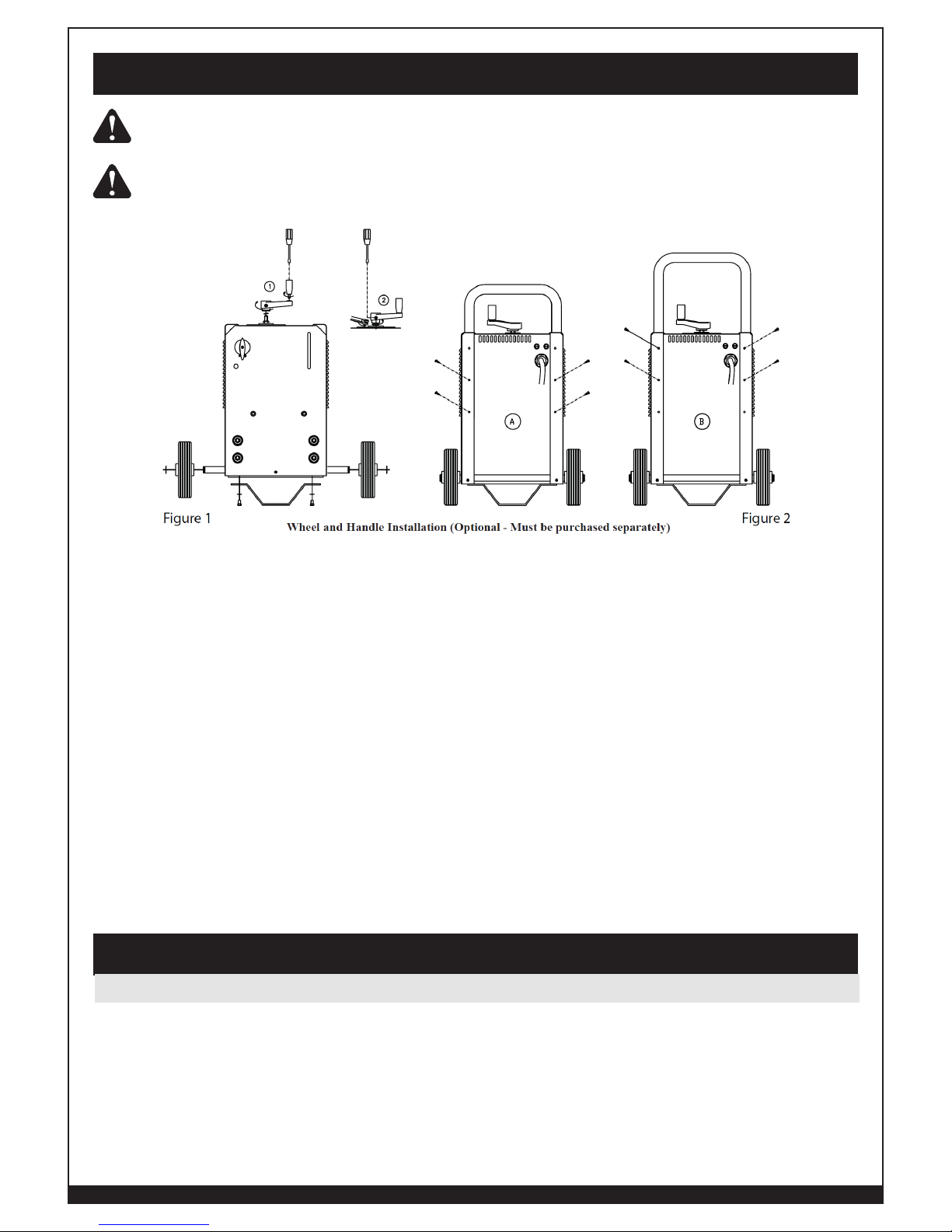
1. Tools required: Hammer, Flat Head Screwdriver, Allen Wrench (metric)
2. Slide the axle through the opening in the bottom of the welder cabinet. Insert axle
into wheels. Use a hammer to attach nuts on the axle by simply tapping them into position.
3. Assemble the handle as shown in Figure 2. It can be placed in 2 different positions.
4. Amperage Adjustment Handle - Thread handle onto shunt control shaft at the top of the
machine until it contacts the locking nut (be sure to install lock washer first). Thread crank
handle into shunt handle. Tighten with a flat blade screwdriver. Tighten lock nut against handle.
Then, tighten the set screw.
5. Place the power source in a well ventilated area. Do not obstruct the air intake and output
vents. A reduced air flow can cause a reduced duty cycle and damage internal components.
6. Ensure at least two feet of open space on each side of the welder.
Your new Forney ARC (SMAW) Welding System is designed for maintenance and sheet metal
fabrication. The unit consists of a single-phase power transformer power source and arc stabilizer.
This welding power source is capable of welding with mild steel electrodes. This unit is also capable of
welding with high carbon steel, special alloy steel, cast iron, and nonferrous, such as aluminum. The
electrode material should correspond with the workpiece metal. Flux coatings are made for use with
either AC (Alternating Current), DC (Direct Current) reverse polarity, or DC straight polarity, although
some function well on both AC and DC current. Please refer to the instructions provided in this manual
for proper machine setup.
Assembly
Installation
Welder Specifications
12
WWW.FORNEYIND.COM
Table 1. Welder Specifications
Type 235 Amp AC/DC ARC Welding System
Input Voltage 220V ±10% (60Hz)
Rated Output 235A @ 20% Duty Cycle
Agency Listing CSA Rated 200A @ 20% Duty Cycle AC
CSA Rated 135A @ 35% Duty Cycle DC
Maximum Output 230A AC Peak / 185A DC Peak
Output Power Settings Shunt (45-235A)
The duty rating defines how long the welding system can be used before it must pause and cool down.
Duty Cycle ratings are expressed as a percentage of a ten-minute period. It represents the maximum
welding time allowed at the specified amperage setting. The remaining balance of a ten-minute period
is required for cooling off the unit.
Please refer to the data plate located on the front of the unit for the specific rating that applies to
your unit. All Forney 230 Volt Welding Systems are rated at the required input amperage for proper
operation. Please refer to the data plate located on the front of the unit for the specific rating that
applies to your unit.
235 AC and 235 AC/DC requires 220V ±10%, 60 Hz, single phase AC with a 50A delayed fuse
or circuit breaker. Please consult local codes for proper plug and receptacle applications. A qualified
electrician should verify the actual voltage at the receptacle into which the welder will be plugged
and confirm that the receptacle is properly grounded. The use of the proper circuit size can eliminate
the nuisance of circuit breaker tripping when welding. This welder must be grounded while in use to
protect the operator from electrical shock. If you are not sure if your outlet is properly grounded, have
it checked by a qualified electrician. NOTE: Do not cut off the grounding prong or alter the plug in any
way. Do not use any adapters between the welder’s power cord and the power source receptacle.
MAKE SURE THE POWER SWITCH IS OFF. Connect the 235 AC / 235 AC/DC to a
properly grounded 230 VAC, single-phase outlet. Contact a qualified electrician if a problem
exists. Improper performance and/or damage to the welder results if operated on inadequate or
excessive power.
HIGH VOLTAGE DANGER FROM POWER SOURCE! Consult a qualified electrician for
proper installation of receptacle at the power source.
Power Source Connection

13
WWW.FORNEYIND.COM
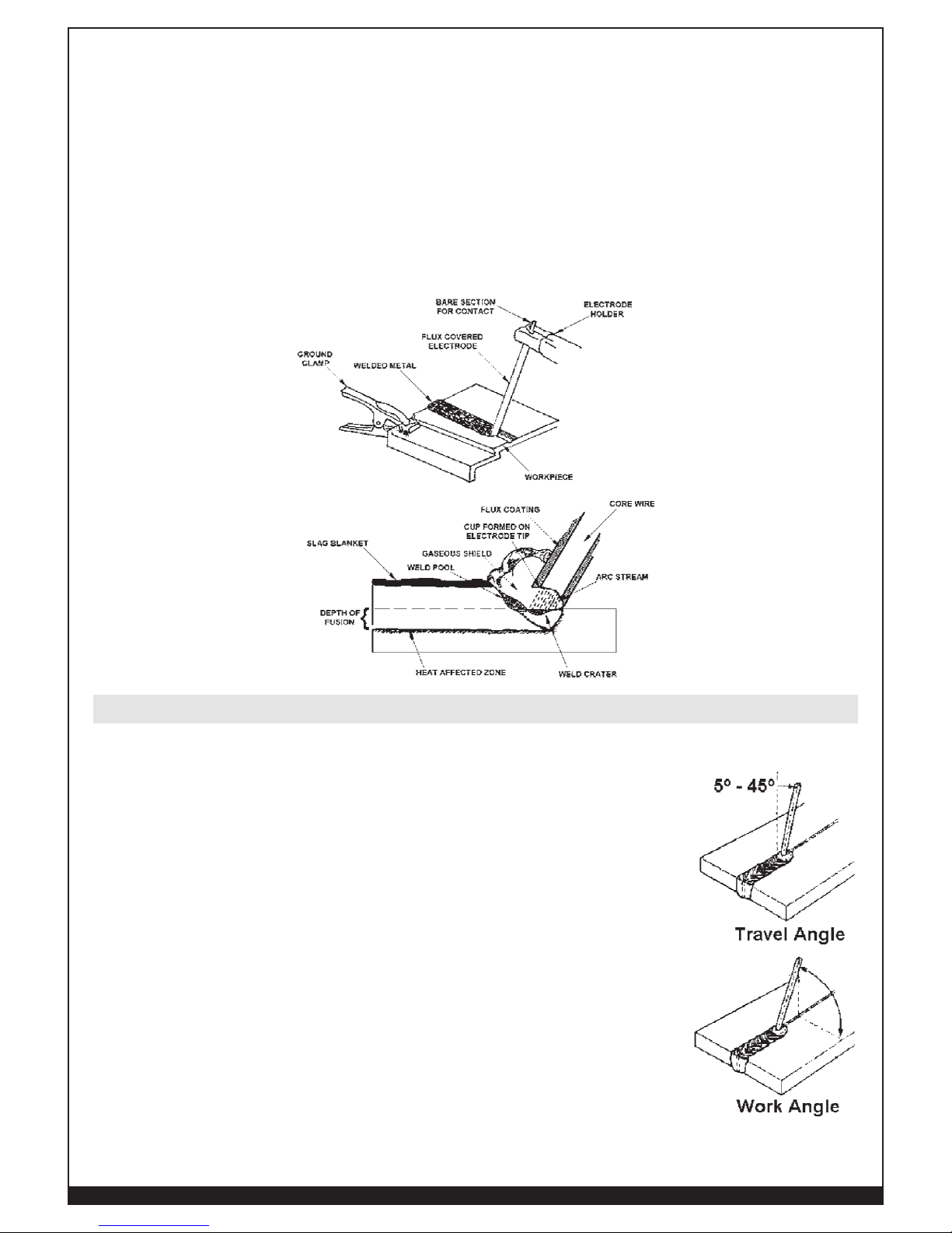
ARC (SMAW - Shielded Metal-Arc Welding) welding metals are bonded by heating them with an
electric arc created between the electrode and the workpiece. There are two parts to electrodes used for
SMAW welding:
1) The inner core is a metal rod or wire that should be similar in composition to the base metal.
2) The outer coat-ing is called flux. There are various types of flux and each coating is used for
a particular welding situation.
When the metal is molten, it can be contaminated by elements in the air. Because this contamination
could weaken the weld, the flux coating creates a protective barrier called slag that protects the molten
metal from contaminants.
When current (amperage) flows through the circuit to the electrode, an arc is formed between the end
of the electrode and the workpiece. The arc melts the electrode and the workpiece. The melted metal
of the electrode flows into the molten crater and forms a bond with the workpiece. There are five basic
choices you must make that affect your weld quality:
1. Electrode selection
2. Current setting
3. Weld angle
4. Arc length
5. Travel speed
ONLY EXPERIENCED PERSONNEL SHOULD USE THE POWER SOURCES.
The use of the proper type of welding current is determined by the type of repair that needs to be made.
Alternating current (AC) welding is performed when the welding cables are connected to the AC
electrode and ground jacks. This type of welding current is ideal for heavy plate steel in flat position
welding. Most AC welding operations will be general purpose work on mild steel utilizing AWS rated
6011 and 7018 type electrodes.
Direct current DC welding is performed when the welding cables are connected to the DC+ (Positive)
and DC-(Negative) output receptacles. The 235 AC/DC offers you two DC welding options, straight
or reverse polarity. To weld with straight polarity place the electrode cable plugged into the receptacle
market DC negative and the ground cable or work cable plugged into the receptacle marked DC
positive.
STRAIGHT POLARITY DC welding is ideal for:
• Cutting steel
• Hardfacing work
• Build up work for heavy deposits
REVERSE POLARITY DC welding is ideal for:
• Overhead welding
• Vertical welding
Operation
Description
Selecting AC or DC Welding Output
14
WWW.FORNEYIND.COM
• Cast Iron welding
• Heavy Aluminum welding
• Rivet welding
• Sheet Metal welding
• Low Hydrogen Electrode welding
• Arc Bronze Electrode welding
This welder has two AC outlet plugs that are clearly marked with the electrode and ground clamp
symbols. Connect the electrode output cable to the electrode connections and the ground cable to the
ground connection. These connections are Dinse type connections and require that they be twisted into
place in order to insure the best connection. A slight twist is fine. You are now able to weld with 30 to
235 Amps of AC Power. The open circuit voltage of the AC connections is approximately 72 Volts.
NEVER REVERSE CABLE CONNECTIONS AS THIS COULD CAUSE INJURY TO THE
USER AS WELL AS DAMAGE TO THE EQUIPMENT.
If you have purchased the 235 AC/DC Model, it has two DC outlet plugs marked DC+ and DC-. These
plugs can be connected in either the DC direct current position or in the DC reverse polarity position.
The DC connectors are Dinse type connections and require a slight twist in order to ensure the best
possible connection. The open circuit voltage of the DC connectors is approximately 72 Volts.
To increase the amperage, simply crank the amperage adjustment handle on top of welder clockwise.
As you crank the handle you will see the amperage indicator located in the sight glass on the amperage
setting scale move upward increasing the amperage. Stop cranking when you have reached the
desired amperage range.
To lower the amperage, simply crank the amperage adjustment handle on top of welder counter
clockwise. As you crank the handle you will see the amperage indicator located in the sight glass on the
amperage setting scale move downward. Stop cranking when you have reached the desired amperage
range.
NOTE: Be sure that the amperage adjustment handle is secured properly and that the screw and nut are
tight. Failure to do so will result in the inability to adjust amperage. Also be careful not to over tighten
the connections which could result in damage to the unit.
The self taught welder learns through a process of trial and error. The best way to teach yourself how to
weld is with short periods of practice at regular intervals. All practice welds should be done on scrap
metal that can be discarded. Do not attempt to make any repairs on valuable equipment until you have
satisfied yourself that your practice welds are of good appearance and free of slag or gas inclusions.
What you fail to learn through practice will be learned through mistakes and re-welds later on.
AC Output Connections
DC Output Connections
Adjusting Amperage
Learning to Weld
15
WWW.FORNEYIND.COM
Your work should be performed in a safe, comfortable and organized area. The work area should be
free of all flammables with both a fire extinguisher and bucket of sand available for emergencies. To
properly prepare for welding follow these simple instructions:
1. Prepare an organized well lighted work area.
2. Follow the instructions for personal protection for yourself as well as those around you.
3. Make sure you’ve studied all safety instructions found at the front of this manual.
4. Set up the workpiece and make the ground clamp connection.
5. Select the appropriate electrode.
6. Turn on the power switch of your welder.
ARC RAYS CAN INJURE EYES AND BURN SKIN! Prolonged exposure to arc rays can
cause blindness and burns. Never strike an arc or begin welding without adequate eye and skin
protection. Wear flameproof welding gloves, a heavy long-sleeved shirt, cuffless pants, hightopped shoes and a welding helmet.
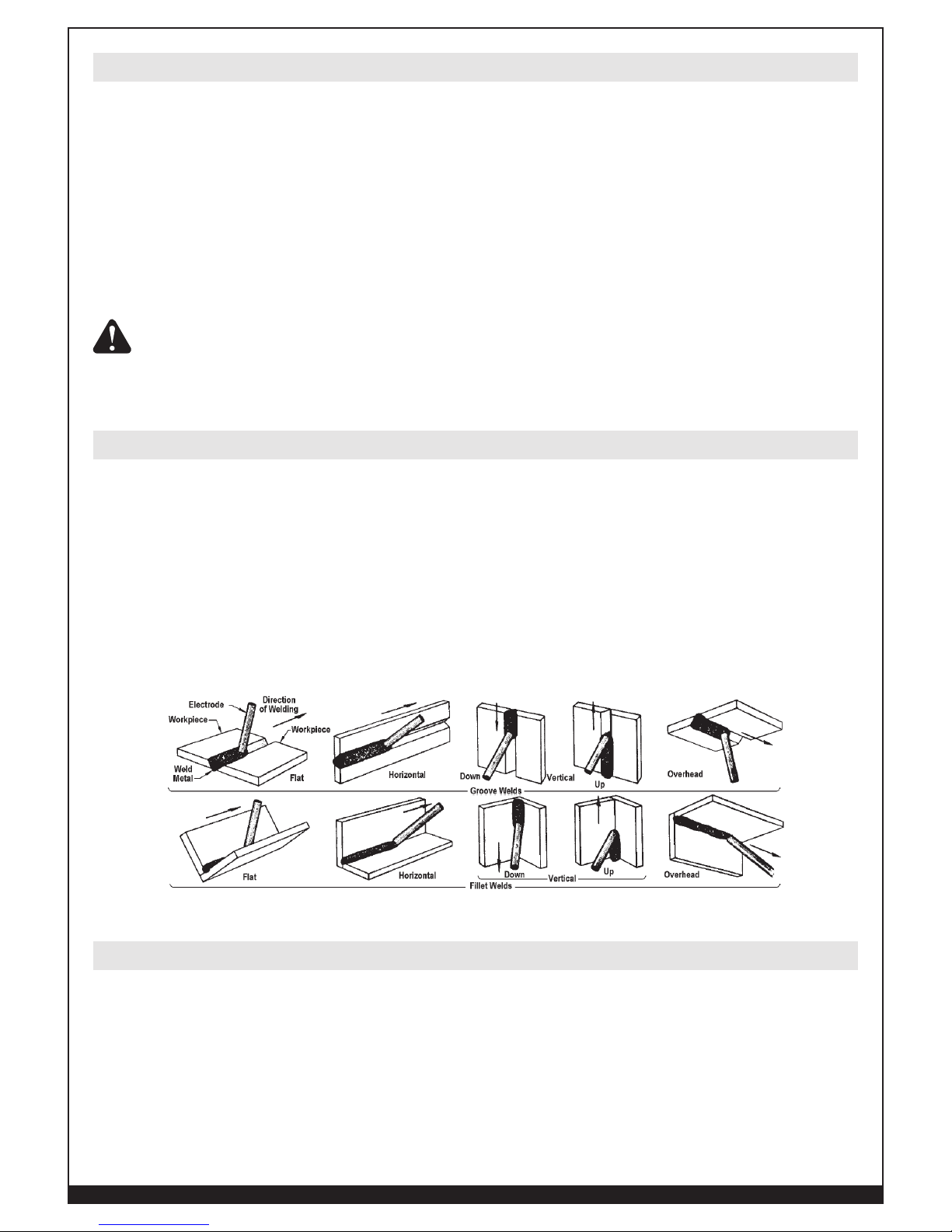
Arc welding can be performed from any of four basic positions:
1. Flat - generally easier, faster, and allows for better penetration of the metal
2. Horizontal - generally easier, faster, and allows for better penetration of the metal
3. Vertical - usually used only when welding with DC welding capabilities
4. Overhead - considered the most difficult, usually used only when welding with DC welding
capabilities
For best results, position the workpiece so that the bead will run on a flat surface.
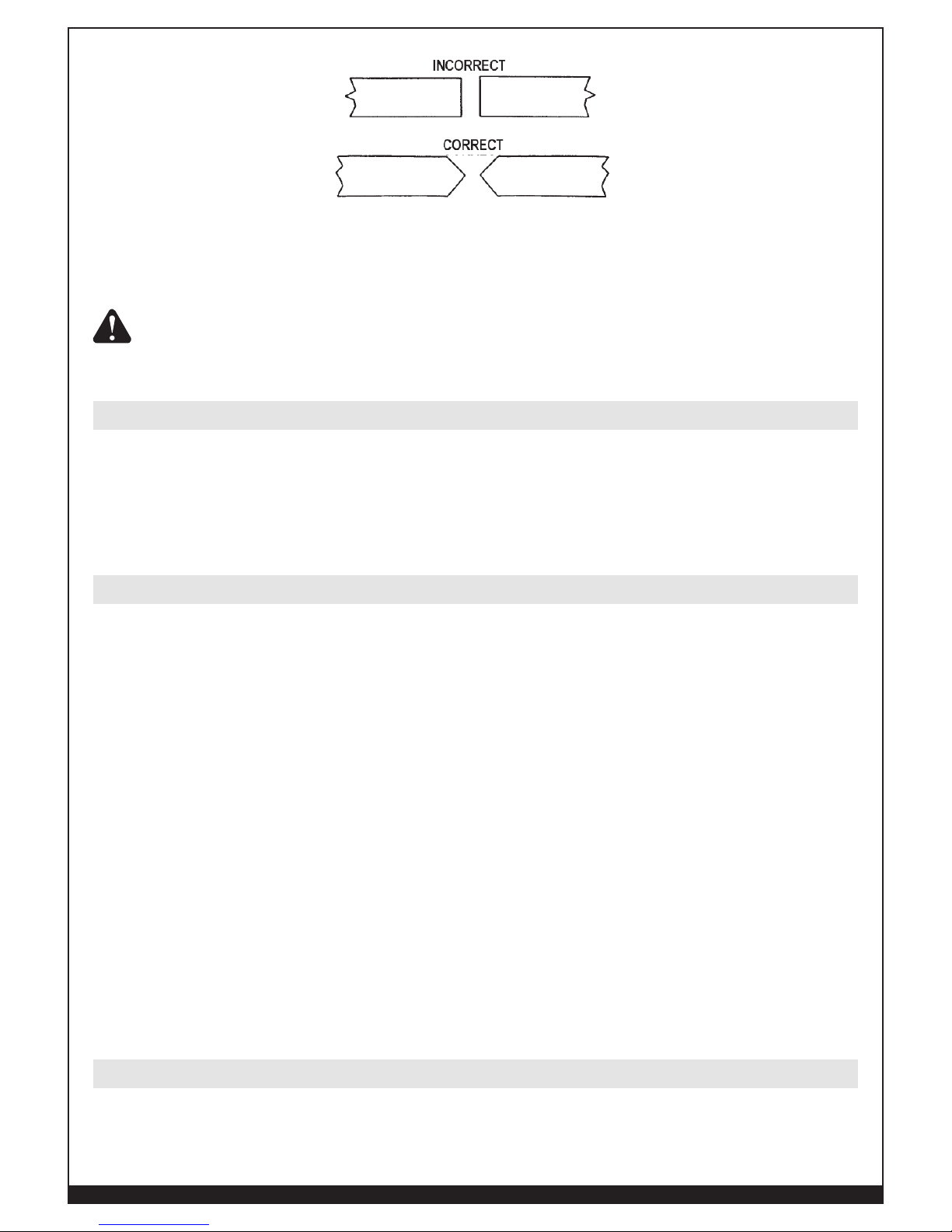
For the most effective welding, surfaces to be joined must be free of dirt, rust, scale, oil or paint.
Welding on metals not properly cleaned will result in brittle or porous welds. If the base metal to be
joined is thick or heavy, it may be necessary to bevel the edges with a metal grinder directly at the point
of contact. The angle of the bevel should be approximately 60 degrees.
Welding Preparation
Welding Positions
Preparing the Joint
16
WWW.FORNEYIND.COM
During the process of welding, workpieces will become very hot and tend to expand. This expansion
may cause the pieces to shift from the beginning position. If possible, workpieces should be clamped
into position required when the welding is completed.
WHEN GRINDING, ALWAYS WEAR GOGGLES AND ENSURE MACHINE GUARDS
ARE IN PLACE THE GRINDER MUST ALSO BE INSPECTED TO VERIFY IT IS IN
GOOD CONDITION.
Be certain you have a solid ground connection. The ground clamp connection is part of the current
circuit. A poor connection at the ground clamp will result in wasted power and heat. Scrape away
any dirt, rust, scale, oil or paint you may find on the workpiece. Make sure the ground clamp directly
touches the metal surface.
The electrode type and thickness of the metal work-piece determine the amount of heat needed in
the welding process. Heavier and thicker metals require more heat or amperage. Refer to a rod and
amperage guide or experiment on scrap metal. When you weld with proper rod, your results will be:
1. Bead will lay smoothly over the workpiece without ragged edges.
2. Base metal puddle will be as deep as the bead that rises above it.
When you weld with rod that is too small, your results will be:
1. Bead will be high and irregular.
2. Arc will be difficult to maintain.
When you weld with rod that is too large, your results will be:
1. Arc will burn through light metals.
2. Bead will undercut the work.
3. Bead will be flat and porous.
4. Rod may freeze or stick to the workpiece.
NOTE: The rate of travel over the workpiece affects the weld. To ensure proper penetration and enough
deposit of rod, move the arc slowly and evenly along the weld seam.
Forney provides a complete set of electrodes. Check with your local dealer for more information.
Welding electrode is a rod or wire of electrically conductive metal, coated with a layer of flux. When
welding, electrical current flows between the electrode or “rod” and the grounded metal workpiece. The
Ground Clamp Connection
Selecting the Proper Amperage
Selecting The Electrode
17
WWW.FORNEYIND.COM
intense heat of the arc between the rod and grounded metal melts the wire and the flux.
The rod wire joins with the base metal of the workpiece to form the weld bead. Burning Flux forms a
gas shield around the arc, helping to control the flow of the fusing metals that form the weld bead.
Type and thickness of the metal and the position of the work piece determines the electrode type and the
amount of heat needed to weld (see diagram below). Heavier and thicker metals require more heat or
amperage.
Although there is no hard and fast rule that determines the exact rod or heat setting required for any
given situation,you can check the rod requirements by referring to the rod guide on your welder, then
experiment on scrap metal.
To strike an arc, bring the tip of the rod in contact with the workpiece surface
and quickly raise it until there is about 1/8 inch (3.2) gap between the rod
and workpiece. The easiest way to strike an arc is to scratch the tip of the rod
(for a short distance) on the workpiece surface (as you would strike a match),
then quickly lift it to the required 1/8 inch (3.2mm). It is important that the
gap be maintained during the welding process and that it be neither too wide
or too narrow. If the gap becomes too narrow, the electrode will freeze or stick
to the workpiece.
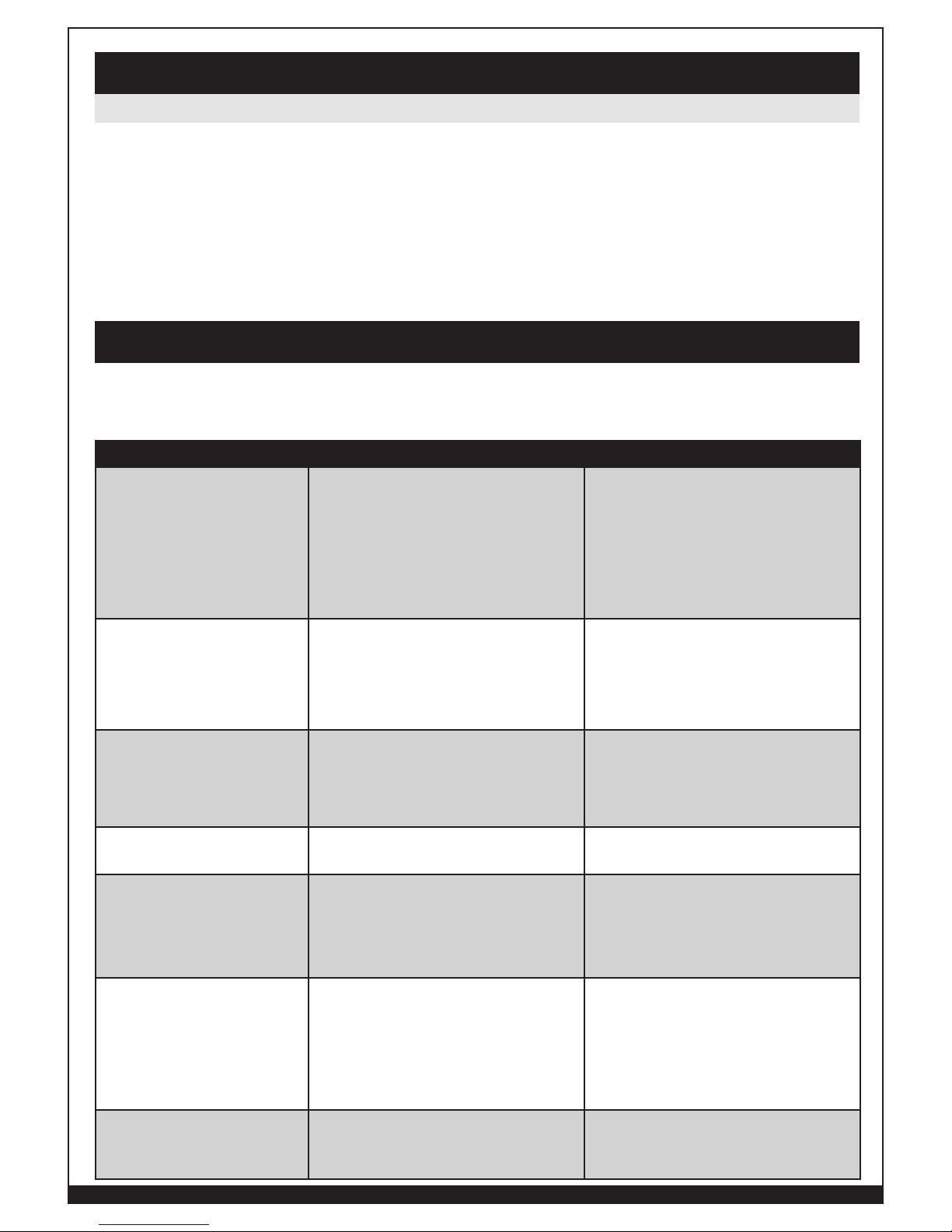
Striking a proper arc and maintaining the gap between the electrode and the
base metal takes practice. Knowing when the arc is just right is a matter of
experience. A good arc is accompanied by a crisp, cracking sound. To lay a
weld bead, only 2 positions are possible (see image):
1. Downward angle (work angle)
2. In the direction the weld is to be laid (travel angle)
Always watch the weld puddle to keep the slag from flowing in front of it to
prevent causing inclusions and gas pockets.
Striking the Arc

18
WWW.FORNEYIND.COM
After learning how to establish and hold an arc, the next step is learning how
to run a good bead. Probably the first attempts in practice will fall short of
acceptable weld beads. Too long an arc will be held or the travel speed will
vary from slow to fast. A solid weld bead requires that the electrode be
moved slowly and steadily along the weld seam. Moving the electrode rapidly
or erratically prevents proper fusion or creates a lumpy, uneven bead.
A solid weld bead requires that the electrode be moved slowly and steadily
along the weld seam. Moving the electrode rapidly or erratically prevents
proper fusion or creates a lumpy, uneven bead.
There are two basic types of weld beads, the stringer bead and the weave bead.
1. The STRINGER BEAD is formed by traveling with the gun in a straight line while keeping the
wire and nozzle centered over the weld joint. This is the easiest type of bead to make.
2. The WEAVE BEAD is used when you want to deposit metal over a wider space than would be
possible with a stringer bead. It is made by weaving from side to side while moving with the
gun. It is best to hesitate momentarily at each side before weaving back the other way.
As the coating on the outside of the electrode burns off, it forms an envelope of protective gasses
around the weld. This prevents air from reaching the molten metal and creating an undesirable
chemical reaction. The burning coating, however, forms slag. Slag formation appears as an
accumulation of dirty metal scale on the finished weld. The slag should be removed with a welding
hammer or chisel, after it is cooled.
WARNING: Peening the slag from a weld joint causes small chips of metal to fly through
the air. Metallic chips flying through the air can cause eye injury or injury to other parts of the
head, hands or exposed portions of the body. Wear eye glasses with side shields and protect the
hands and other exposed parts of the body with protective garments or if possible work with a
shield between the body and the workpiece.
Arc Welding Techniques
Types of Commonly Used Weld Beads
19
WWW.FORNEYIND.COM
This welder has been engineered to give many years of trouble-free service providing that a few very
simple steps are taken to properly maintain it.
• Replace power cord, ground cable, ground clamp, or electrode assembly when damaged
or worn.
• Periodically clean dust, dirt, grease, etc. from your welder.
• Every six months, or as necessary, remove the cover panel from the welder and air-blow any
dust and dirt that may have accumulated inside the welder.
This chart will assist you in resolving common problems you may encounter. These are not all the possible
solutions.
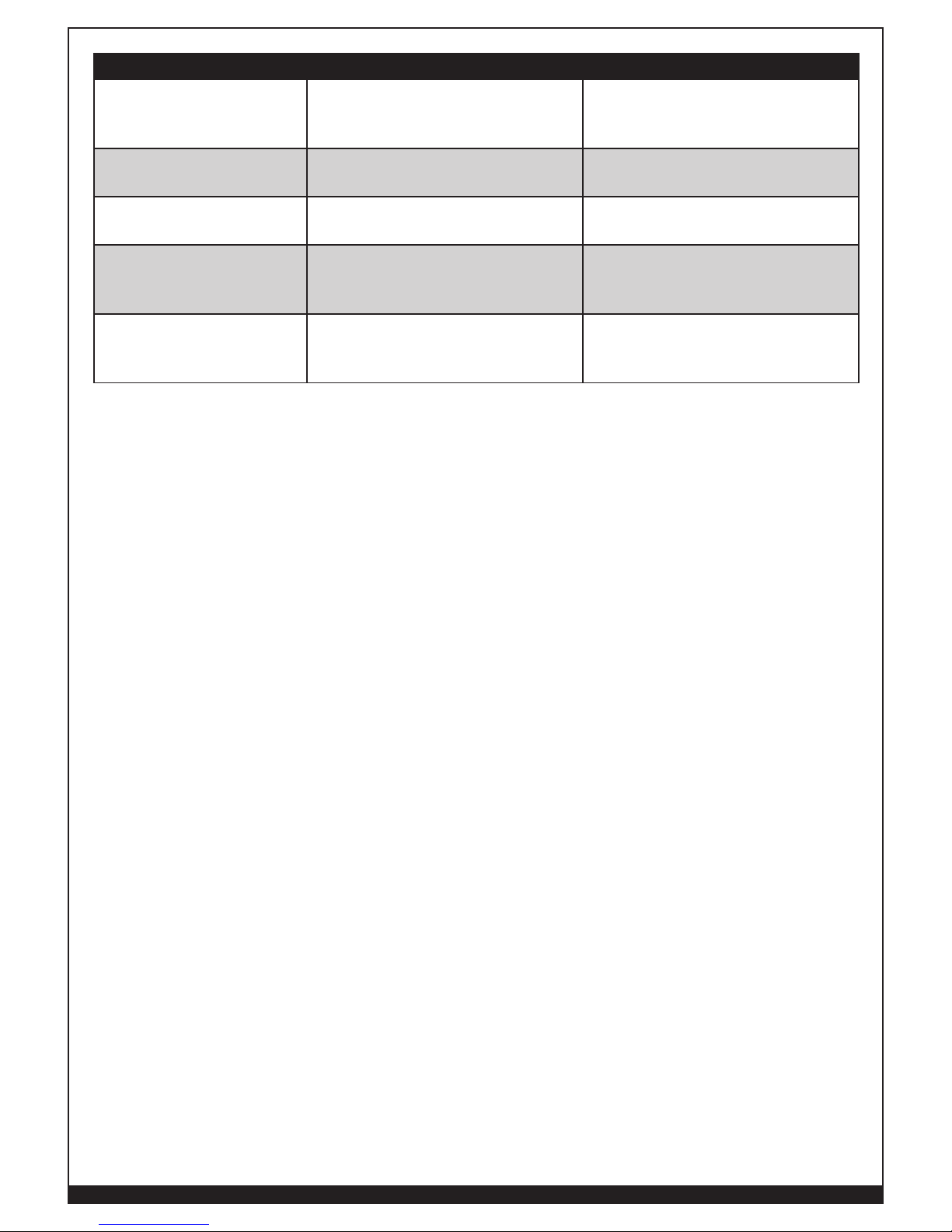
PROBLEM POSSIBLE CAUSE POSSIBLE SOLUTION
Welder does not hum
when turned on
1. No power at receptacle
2. Broken or damaged power cord
3. Faulty switch
4. Faulty transformer
1. Check circuit and fuses or circuitbreakers back at meter
2. Replace power cord
3. Switch needs to be replaced
4. Transformer needs to be
replaced
Welder humbs but will not
weld
1. Inadequate power at the
receptacle
2. Inadequate current at the arc
3. Poor connections at the welder
1. Check power supplies
2. Check ground clamp cable and
connection to work piece; check
electrode cable and clamp at
electrode
Welder gives shocks 1. Incorrect connections at power
cord or receptacle (hot wire
connected to ground terminal)
2. Welder wired to 3-phase current
1. Rewire power cord receptacle
2. Check power source
Welder heat setting difficult
to adjust
Dust or dirt moving inside
transformer
Clean shunt track
Welder overheats/blows
fuses
1. Fan blade not turning or obstructed
2. Fan turning too slowly - misaligned
bearings
3. Wrong amperage fuse in fuse box
1. Clear blade of obstruction and/or
replace fan motor
2. Replace fan motor & bearings
3. Replace with 50 amp or breaker
Arc hard to strike 1. Wrong type of electrode or
electrode too large
2. Base metal not grounded
properly
3. Voltage from power line low due
to heavy loads
1. Check electrode and verify size
and type of electrode for application
2. Verify grounding
3. Have power company verify
voltage and increase if possible
Bead too thin in places Uneven speed in moving electrode
across base metal
Slow down; try to maintain steady
rate of travel across the surface to
be welded.
Maintenance & Servicing
General Maintenance
Troubleshooting
20
WWW.FORNEYIND.COM
PROBLEM POSSIBLE CAUSE POSSIBLE SOLUTION
Bead too thick in places Holding the electrode too long in
one place or moving it too slowly
across the base metal
Speed up; maintain a uniform rate
of speed along the bead
Ragged depressions at
edge of weld
Moving the electrode too rapidly or
holding too short an arc
Slow down; lengthen the arc
slightly
Overlapping beads Arc too long or rate of travel too
fast
Slow down
Electrode sticks to work Electrode is held in contact with
base metal while arc is struck
Move electrode away from the base
metal immediately after the arc is
struck
Poor electrode
performance/electrodes
sputter and stick
1. Damp electrodes
2. Wrong type of electrode
1. Store electrodes in a dry location
2. Use correct electrode

21
WWW.FORNEYIND.COM
Wiring Diagram

22
WWW.FORNEYIND.COM
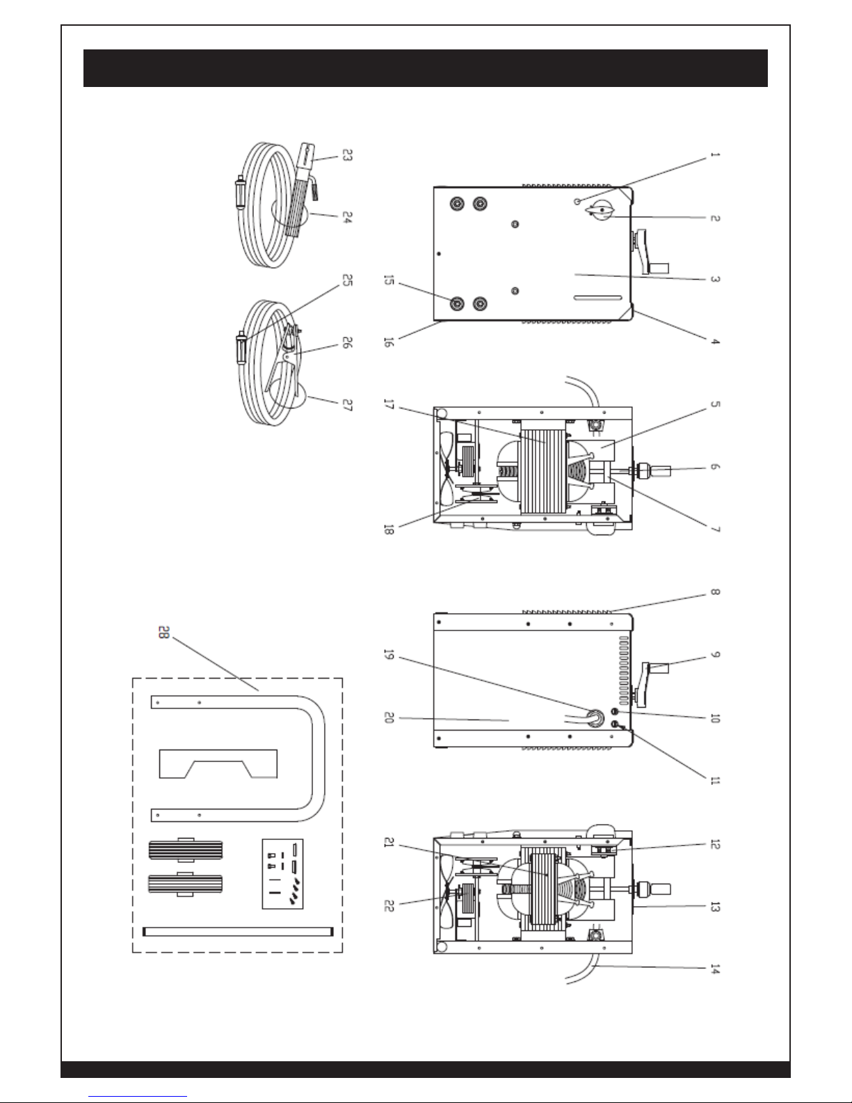
REF. # PART # ITEM DESCRIPTION
1 85014 GREEN PILOT-LAMP 220V L=230 1 PC PACK
2 85113 KNOB D.45 FOR BLACK SWITCH + INDEX
3 85117 FRONT AND BACK PANEL FORNEY 235FI AC/DC
4 85123 UPPER HOLE CAP (HANDLE HOLES)
5 85074 MAGNETIC SHUNT 25X39 X172 2 PC PACK
6 85132 REGULAT. SCREW +WASHER L=180 FIL.M8 1PC
7 85133 SHUNT YOKE D.15 L=107 1PC PACK
8 85118 RIGHT UPPER PANEL FORNEY 235 AC/DC
9 85303 HAND-WHEEL R=65 +KNOB
10 85130 FUSE HOLDER PTF/70 6,3A 250V
11 85129 FUSE 5X20 T 2A 250V 10PCS PACK
12 85128 SWITCH 32 A A 3202
13 85111 D.120 GROMMET + D.40 BUSH KIT
14 85120 INPUT CABLE ST3XAWG10 2,5M+50A-PLUG 1PC
15 85009 FEM.DINSE PLUG 25SQMM CX30 (1 PC PACK)
16 85124 LOWER HOLE CAP D.15-21,5
17 85112 TRANSFORMER COMPLETE 250 AC/DC 60HZ 230V
18 85131 RECTIFIER
19 85121 CABLE CLAMP HOLE D.30
20 85119 BACK PANEL FORNEY 235 AC/DC
21 85110 WINDING + "E" CORE LAMINATIONS 235 AC/DC
22 85050 FAN C30 220V 60HZ 175 1PC PACK
23 85127 ELECTRODE HOLDER EH-IT01 300A 1PC PACK
24 85134 WELDING CABLE 25MM2 3M EH-IT01/DN25 1PC
25 84963 DINSE PLUG 25MM2 1 PC PACK
26 85011 EARTH CLAMP 300A ZINC-COATED 1 PC PACK
27 85136 EARTH CABLE 25SQMM MT.2
28 329 KIT WHEELS AND HANDLE 235FI AC - AC/DC
Spare Parts List
23
WWW.FORNEYIND.COM
Spare Parts Diagram

24
WWW.FORNEYIND.COM
_______________________________________________________________________________________
_______________________________________________________________________________________
_______________________________________________________________________________________
_______________________________________________________________________________________
_______________________________________________________________________________________
_______________________________________________________________________________________
_______________________________________________________________________________________
_______________________________________________________________________________________
_______________________________________________________________________________________
_______________________________________________________________________________________
_______________________________________________________________________________________
_______________________________________________________________________________________
_______________________________________________________________________________________
_______________________________________________________________________________________
_______________________________________________________________________________________
_______________________________________________________________________________________
_______________________________________________________________________________________
_______________________________________________________________________________________
_______________________________________________________________________________________
_______________________________________________________________________________________
_______________________________________________________________________________________
_______________________________________________________________________________________
_______________________________________________________________________________________
_______________________________________________________________________________________
_______________________________________________________________________________________
_______________________________________________________________________________________
_______________________________________________________________________________________
_______________________________________________________________________________________
_______________________________________________________________________________________
_______________________________________________________________________________________
_______________________________________________________________________________________
_______________________________________________________________________________________
_______________________________________________________________________________________
_______________________________________________________________________________________
_______________________________________________________________________________________
_______________________________________________________________________________________
_______________________________________________________________________________________
_______________________________________________________________________________________
_______________________________________________________________________________________
_______________________________________________________________________________________
_______________________________________________________________________________________
_______________________________________________________________________________________
_______________________________________________________________________________________
_______________________________________________________________________________________
_______________________________________________________________________________________
_______________________________________________________________________________________
_______________________________________________________________________________________
_______________________________________________________________________________________
_______________________________________________________________________________________
_______________________________________________________________________________________
User Notes
 Loading...