

Forney 190 MP, 140 Operating Manual

1
WWW.FORNEYIND.COM
CAT# 324
REV 11.09.2015
FEATURES:
• A Multi-Process inverter machine capable
of MIG, Stick, or TIG Welding
• Power saving and versatile inverter
technology allows for use with either
230/120V input
• Welding range up to 190 Amps
• Can be used for Steel, Stainless Steel, and
Aluminum
• Easy to change between welding processes
• Premium MIG torch with Euro disconnect
and Tweco® style consumables
• Advanced synergic electronics allow for
outstanding arc control for all processes
• Metallic heavy-duty wire drive system
• Optional spool gun increases flexibility
• Large cabinet with easy access spools
• Digital readouts
IDEAL FOR:
General Fabrication, Auto Body, Farm & Ranch,
Maintenance, Sheet Metal, Contractor, and More...
INCLUDES:
Power cord adapter 230-120V, MIG Torch,
Ground Cable and Clamp, Stick Electrode
Holder, Power Cable, Gas Hose and Regulator
190 MULTI-PROCESSOR
OPERATING MANUAL
ENGLISH

2
WWW.FORNEYIND.COM
STOP!
PLEASE DO NOT
RETURN TO THE STORE
If you have questions or problems with your new welder, please
call customer service at 1-800-521-6038
Monday through Friday from 7 a.m. - 5 p.m. (MST) or at
www.forneyind.com/customer_service.
Please take time to register your product at
www.forneyind.com/customer_service/register_your_product/
Thank you, enjoy your new welder.

3
WWW.FORNEYIND.COM
Forney Promise
We are committed to your success regardless of location, size or
needs. We understand it is your goal to get the job done right,
and we are ready to help you do just that.
President's Message
We market the highest quality tools, equipment and accessories
for the do-it-yourselfer and professional. Our passion and
dedication in bringing new products to the industrial and retail
market, combined with our personal service, is unmatched in our
industry. Our ability to listen to our customers’ needs enables us to
create solutions to their problems.
Our dedication to the highest quality customer service within our
corporate headquarters and the service provided in the field is
unequaled. We are committed to creating the best solutions to our
customer’s needs. Above all, our employees will provide the same
respect and caring attitude within the organization as they are
expected to share with every Forney customer. Our goal will be to
exceed our customers’ expectations through empowered people,
guided by shared values and commitments.
We work hard so our customers trust us because of our integrity,
teamwork and innovation of Forney products, and Forney’s
80 years of unmatched product quality and an unwavering
commitment to our customers.
When our customers succeed we succeed.
STEVEN G. ANDERSON, President & CEO
Copyright© 2014 Forney Industries,
Inc. All rights reserved. Unauthorized
reproduction and/or distribution is
subject to US copyright laws.
U.S. Warehouses:
- Fort Collins, CO
- Tipp City, OH
FIVE WAYS TO ORDER
Web: www.forneyind.com
Phone: 80 0-521-6038
Fax: 970-498-9505
Mail: Forney Industries
2057 Vermont Drive
Fort Collins, CO 80525
Email: sales@forneyind.com

4
WWW.FORNEYIND.COM
Forney 5/3/1 Limited Warranty
Effective August 1, 2009
1) Limited Warranty - Subject to the terms and conditions below, Forney Industris, Inc., Fort Collins,
Colorado, warrants to its original retail purchaser that the new Forney equipment sold after the effective date
of this limited warranty is free of defects in material and workmanship at the time it is shipped by Forney. This
is in lieu of all other warranties, expressed or implied.
2) Notifications: Please call 1-800-521-6038 with your warranty questions. You can also visit:
www.forneyind.com for additional information about your new welder or plasma system.
3) Length of Warranty: Within the warranty periods listed below, Forney will repair or replace any
warranted parts or components that fail due to defects in material or workmanship. Warranty is effective
from the date of original retail purchase. Warranty duration is as follows.
A) 5 years: Original main power rectifiers only to include SCRs, diodes and discrete rectifier modules,
transformers, stabilizers, and reactors.
B) 3 years: Drive Systems, PC Boards, Motors, and Switches and Controls
C) 1 year: MIG guns, relays, contactors, and regulators, plasma cutting torches, and accessories.
D) 90 days: Replacement parts. Does not include labor.
4) Forney’s limited warranty shall not apply to consumables such as contact tips, cutting nozzles, felt wire
cleaner, drive rollers, gas diffusers, plasma torch tips and electrodes, weld cables, tips and parts that fail
due to normal wear. In addition, this warranty does not extend to any damage caused by the untimely
replacement or maintenance of any of the previously listed consumable parts.
5) Warrantor:
Forney Industries
2057 Vermont Drive
Fort Collins, CO 80525
1-800-521-6038
www.forneyind.com
6) Purchaser / Warranty: The original purchaser of the Forney Industries product. The warranty is
not transferable. Forney Industries products are intended for purchase and use by persons trained and
experienced in the use and maintenance of welding equipment.
7) What is not covered under the warranty:
A) Implied warranties, including those of merchantability and fitness for a particular purpose are limited in duration
to this express warranty. After this period, all risk of loss, from whatever reason, shall be on the purchaser.
B) Any incidental, indirect, or consequential loss, damage, or expense that may result from any defect,
failure or malfunction of the Forney product.
C) Any failure that results from accident, purchaser’s abuse, neglect or failure to operate products in
accordance with instructions provided in the owner’s manual(s) supplied with the product.
D) Pre-delivery service, i.e. assembly and adjustment.
8) Claim: In the event of a warranty claim under this warranty, the exclusive remedies shall be, at Forney
Industries sole option:
A) Repair; or
B) Replacement; or
C) Where authorized in writing by Forney Industries, the cost of repair or replacement at an authorized
Forney Industries service station; or
D) Payment of or credit for the purchase price less reasonable depreciation based on actual use upon the
return of the goods at the customer’s risk and expense.
9) Purchaser will:
A) Contact Forney’s customer service at 1-800-521-6038 within 30 days of the defect or failure.
B) Provide dated proof of purchase (typically a purchase receipt).
C) Provide the serial number. Registering your welder at forneywelding.forneyind.com will speed up this process.
D) Deliver or ship welder to a Forney authorized service center. Freight &/or packaging costs, if any, must
be borne by the purchaser.

5
WWW.FORNEYIND.COM
CAUTION!
BEFORE INSTALLING, OPERATING OR CARRYING OUT MAINTENANCE ON THE MACHINE, READ THE CONTENTS OF THIS MANUAL
CAREFULLY, PAYING PARTICULAR ATTENTION TO THE SAFETY RULES AND HAZARDS.
In the event of these instructions not being clear, please contact your
Forney Authorized Dealer or Forney Customer Service 1-800-521-6038
• Safety in Welding and Cutting, ANSI Standard Z49.1, from American Welding Society, 8669 Doral
Boulevard, Suite 130, Doral, FL 33166 Safety and Health Standards, OSHA 29 CFR 1910, from
Superintendent of Documents, U.S. Government Printing Office, Washington, D.C. 20402.
• Recommended Safe Practices for the Preparation for Welding and Cutting of Containers That Have
Held Hazardous Substances, American Welding Society Standard AWS F4.1, from American
Welding Society, 8669 Doral Boulevard, Suite 130, Doral, FL 33166
• National Electrical Code, NFPA Standard 70, from National Fire Protection Association,
Batterymarch Park, Quincy, MA 02269.
• Safe Handling of Compressed Gases in Cylinders, CGA Pamphlet P-1, from Compressed Gas
Association, 1235 Jefferson Davis Highway, Suite 501, Arlington, VA 22202.
• Code for Safety in Welding and Cutting, CSA Standard W117.2, from Canadian Standards
Association, Standards Sales, 178 Rexdale Boulevard, Rexdale, Ontario, Canada M9W 1R3.
• Safe Practices For Occupation And Educational Eye And Face Protection, ANSI Standard Z87.1,
from American National Standards Institute, 1430 Broadway, New York, NY 10018.
• Cutting And Welding Processes, NFPA Standard 51B, from National Fire Protection Association,
Batterymarch Park, Quincy, MA 02269
California Proposition 65 Warning
This product may contain chemicals known to the State of California to cause cancer, birth defects and
other reproductive harm (CA. Prop 65). Wash hands after use.
EMF Information
Welding or cutting current, as it flows through the welding or cutting cables, will cause electromagnetic
fields. There has been and still is some concern about such fields. However, after examination the
committee of the National Research Council concluded that: “The body of evidence, in the committee’s
judgment, has not demonstrated that exposure to power-frequency electric and a magnetic field is a
human health hazard.” However, studies are still going forth and evidence continues to be examined.
Until the final conclusions of the research are reached, you may wish to minimize your exposure to
electromagnetic fields when welding or cutting.
To reduce magnetic fields in the workplace, use the following procedures:
1. Keep cables close together by twisting or taping them.
2. Arrange cables to one side and away from the operator.
3. Do not coil or drape cables around your body.
4. Keep welding or cutting power source and cables as far away from operator as practical.
5. Connect work clamp to work piece as close to the cut or weld as possible.
ABOUT PACEMAKERS & HEARING AIDS:
Pacemaker & Hearing Aid wearers consult your doctor first. If cleared by your doctor, then following
the above procedures is recommended.
Safety Information
Principal Safety Standards

6
WWW.FORNEYIND.COM
Personal Protection
Welding processes of any kind can be dangerous not only to the operator but to any person situated
near the equipment, if safety and operating rules are not strictly observed.
THE WELDING ARC PRODUCES VERY BRIGHT ULTRAVIOLET AND INFRARED
LIGHT. THESE ARC RAYS WILL DAMAGE YOUR EYES AND BURN YOUR SKIN IF
YOU ARE NOT PROPERLY PROTECTED. To reduce the risk of injury from arc rays, read,
understand, and follow the safety instructions. In addition, make certain that anyone else that
uses this welding equipment, or is a bystander in the welding area understands and follows
these safety instructions as well. Helmets and filter should conform to ANSI Z87.1 stan dards.
• Do not look at an electric arc without proper protection. A welding arc is extremely bright
and intense and, with inadequate or no eye protection, the retina can be burned, leav ing
a permanent dark spot in the field of vision. A shield or helmet with a #10 shade filter lens
(minimum) must be used.
• Do not strike a welding arc until all bystanders and you (the welder) have welding shields
and/or helmets in place.
• Do not wear a cracked or broken helmet and replace any cracked or bro ken filter lenses
immediately.
• Do not allow the uninsulated portion of the wire feed gun to touch the ground clamp or
grounded work to prevent an arc flash from being created on contact.
• Provide bystanders with shields or hel mets fitted with an appropriate shade filter lens.
• Wear protective clothing. The intense light of the welding arc can burn the skin in much
the same way as the sun, even through light-weight clothing. Wear dark clothing of heavy
material. The shirt worn should be long sleeved and the collar kept buttoned to protect chest
and neck.
• Protect against reflected arc rays. Arc rays can be reflected off shiny sur faces such as a glossy
painted surface, aluminum, stainless steel, and glass. It is possible for your eyes to be injured
by reflected arc rays even when wearing a protective helmet or shield. If welding with a
reflective surface behind you, arc rays can bounce off the surface and off the fil ter lens. It can
get inside your helmet or shield and into your eyes. If a reflective background exists in your
welding area, either remove it or cover it with something non-flammable and non-reflective.
Reflective arc rays can also cause skin burn in addition to eye injury.
• Flying sparks can injure. Wear proper safety equipment to protect eyes and face. Shape
tungsten electrode on grinder wearing proper protection and in a safe location. Keep
flammables away and prevent fire from flying sparks.
FUMES, GASSES, AND VAPORS CAN CAUSE DISCOMFORT, ILLNESS, AND
DEATH! To reduce the risk, read, understand, and follow the safety instructions. In addition,
make certain that anyone else that uses this welding equipment or is a bystander in the welding
area, understands and follows these safety instructions as well.
• Read and understand manufacturers SDS and MSDS.
• Do not weld in an area until it is checked for adequate ventilation as described in ANSI
standard Z49.1. If ventilation is not adequate to exchange all fumes and gasses generated
during the welding process with fresh air, do not weld unless you (the welder) and all
bystanders are wearing air-supplied respirators.
• Do not heat metals coated with, or that contain, materials that produce toxic fumes (such as
galvanized steel), unless the coating is removed. Make certain the area is well ventilated, and
the operator and all bystanders are wearing air-sup plied respirators.
• Do not weld, cut or heat lead, zinc, cad mium, mercury, beryllium, antimony, cobalt,
manganese, selenium, arsenic, copper, silver, barium, chromium, vanadium, nickel, or similar
met als without seeking professional advice and inspection of the ventilation of the welding

7
WWW.FORNEYIND.COM
area. These metals produce extremely toxic fumes which can cause discomfort, illness and
death.
• Do not weld or cut in areas that are near chlorinated solvents. Vapors from chlori nated
hydrocarbons, such as trichloroeth ylene and perchloroethylene, can be decomposed by the
heat of an electric arc or its ultraviolet radiation. These actions can cause phosgene, a high ly
toxic gas, to form, along with other lung and eye-irritating gasses. Do not weld or cut where
these solvent vapors can be drawn into the work area or where the ultraviolet radiation can
pene trate to areas containing even very small amounts of these vapors.
• Do not weld in a confined area unless it is being ventilated or the operator (and anyone else
in the area) is wearing an air-supplied respirator.
• Stop welding if you develop momentary eye, nose, or throat irritation as this indi cates
inadequate ventilation. Stop work and take necessary steps to improve ventilation in the
welding area. Do not resume welding if physical discomfort persists.
Fire Prevention
FIRE OR EXPLOSION CAN CAUSE DEATH, INJURY, AND PROPERTY DAMAGE!
To reduce these risks, read, understand and follow the safety instructions. In addition, make
certain that anyone else that uses this welding equip ment, or is a bystander in the welding
area, understands and follows these safety instruc tions as well. Remember: arc welding by
nature produces sparks, hot spatter, molten metal drops, hot slag and hot metal parts that can
start fires, burn skin and damage eyes.
• Do not wear gloves or other clothing that contains oil, grease, or other flammable
substances.
• Do not wear flammable hair preparations.
• Do not touch the hot weld bead or weld puddle until fully cooled.
• Do not weld in an area until it is checked and cleared of combustible and/or flam mable
materials. Be aware that sparks and slag can fly 35 feet and can pass through small cracks
and openings. If work and combustibles cannot be sepa rated by a minimum of 35 feet,
protect against ignition with suitable, snug-fitting, fire resistant, covers or shields.
• Do not weld on walls until checking for and removing combustibles touching the other side of
the walls.
• Do not weld, cut, or perform other such work on used barrels, drums, tanks, or other
containers that had a flammable or toxic substance. The tech niques for removing flammable
sub stance and vapors, to make a used con tainer safe for welding or cutting, are quite
complex and require special educa tion and training.
• Do not strike an arc on a compressed gas or air cylinder. Doing so will create a brittle
area that can result in a violent rupture immediately or at a later time as a result of rough
handling.
• Do not weld or cut in an area where the air may contain flammable dust (such as grain
dust), gas, or liquid vapors (such as gasoline).
• Do not handle hot metal, such as the work piece or electrode stubs, with bare hands.
• Wear leather gloves, heavy long sleeve shirt, cuffless pants, high-topped shoes, helmet, and
cap. As necessary, use additional protective clothing such as leather jacket or sleeves, fire
resistant leggings, or apron. Hot sparks or metal can lodge in rolled up sleeves, pant cuffs,
or pockets. Sleeves and collars should be kept buttoned and pockets eliminated from the shirt
front.
• Have fire extinguisher equipment handy for immediate use. A portable chemical fire
extinguisher, type ABC, is recom mended.
• Wear ear plugs when welding overhead to prevent spatter or slag from falling into ear.
• Make sure welding area has a good, solid, safe floor, preferably concrete or masonry, not
tiled, carpeted, or made of any other flammable material.
• Protect flammable walls, ceilings, and floors with heat resistant covers or shields.

8
WWW.FORNEYIND.COM
• Check welding area to make sure it is free of sparks, glowing metal or slag, and flames
before leaving the welding area.
• Wear garments free of oil or other flammable substances such as leather gloves, thick cotton
shirts with no synthetic materials, cuffless trousers, closed toed shoes. Keep long hair pulled
back.
• Remove any combustibles such as lighters and matches before doing any welding.
• Follow requirements in OSHA and NFPA for hot work and have an extinguisher nearby.
High Frequency Radiation
• High Frequency (H.F) can interfere with radio navigation, safety services, computers and
communication equipment.
• It is the user’s responsibility to have a qualified electrician promptly correct any interference
problem resulting from the installation. Electrician should regularly check and maintain
installation.
• Stop using the equipment if notified by the FCC about interference.
• Keep H.F. source doors and panels tightly shut and keep spark gaps at correct setting.
Arc Welding
• Computers and computer driven equipment can be harmed with electromagnetic energy.
• Be sure all equipment is compatible with electromagnetic energy.
• Keep welding cables short to reduce interference.
• Follow manual to install and ground machine.
• If interference continues, shield the work area or move the welding machine.
WARNING: ELECTRIC SHOCK CAN KILL! To reduce the risk of death or serious injury
from shock, read, understand, and follow the safety instructions. In addition, make certain
that anyone else who uses this welding equipment, or who is a bystander in the welding area
understands and follows these safety instructions as well.
IMPORTANT! TO REDUCE THE RISK OF DEATH, INJURY, OR PROPERTY
DAMAGE, DO NOT ATTEMPT OPERA TION of this welding equipment until you have read
and understand the following safety summary.
• Do not, in any manner, come into physi cal contact with any part of the welding current
circuit. The welding current circuit includes:
a. the work piece or any conductive material in contact with it,
b. the ground clamp,
c. the electrode or welding wire,
d. any metal parts on the electrode holder, or wire feed gun.
• Do not weld in a damp area or come in contact with a moist or wet surface.
• Do not attempt to weld if any part of clothing or body is wet.
• Do not allow the welding equipment to come in contact with water or moisture.
• Do not drag welding cables, wire feed gun, or welder power cord through or allow them to
come into contact with water or moisture.
• Do not touch welder, attempt to turn welder on or off if any part of the body or clothing is
moist or if you are in physical contact with water or moisture.
• Do not attempt to plug the welder into the power source if any part of body or cloth ing is
moist, or if you are in physical con tact with water or moisture.
• Do not connect welder work piece clamp to or weld on electrical conduit.
Electric Shock

9
WWW.FORNEYIND.COM
• Do not alter power cord or power cord plug in any way.
• Do not attempt to plug the welder into the power source if the ground prong on power cord
plug is bent over, broken off, or missing.
• Do not allow the welder to be connected to the power source or attempt to weld if the welder,
welding cables, welding site, or welder power cord are exposed to any form of atmospheric
precipitation, or salt water spray.
• Do not carry coiled welding cables around shoulders, or any other part of the body, when
they are plugged into the welder.
• Do not modify any wiring, ground connections, switches, or fuses in this welding equipment.
• Wear welding gloves to help insulate hands from welding circuit.
• Keep all liquid containers far enough away from the welder and work area so that if spilled,
the liquid cannot possibly come in contact with any part of the welder or electrical welding
circuit.
• Replace any cracked or damaged parts that are insulated or act as insulators such as
welding cables, power cord, or electrode holder immediately.
• When not welding, cut wire back to contact tip or remove electrode from electrode holder.
Noise
Noise can cause permanent hearing loss. Welding processes can cause noise levels that exceed
safe limits. You must protect your ears from loud noise to prevent permanent loss of hearing.
• To protect your hearing from loud noise, wear protective ear plugs and/or ear muffs.
• Noise levels should be measured to be sure the decibels (sound) do not exceed safe levels.
Additional Safety Information
For additional information concerning weld ing safety, refer to the following standards and comply with
them as applicable.
• ANSI Standard Z49.1 - SAFETY IN WELDING AND CUTTING - obtainable from the
American Welding Society, 550 NW Le Jeune Road, Miami, FL 33126 Telephone (800)
443-9353, Fax (305) 443-7559 - www.amweld.org or www.aws.org
• ANSI Standard Z87.1 - SAFE PRAC TICE FOR OCCUPATION AND EDUCA TIONAL EYE
AND FACE PROTECTION - obtainable from the American National Standards Institute, 11
West 42nd St., New York, NY 10036 Telephone (212) 642A900, Fax (212) 398-0023 www.ansi.org
• NFPA Standard 518 - CUTTING AND WELDING PROCESS - obtainable from the National
Fire Protection Association, 1 Batterymarch Park, P.O. Box 9101, Quincy, MA 02269-9101
Telephone (617) 770-3000 Fax (617) 770-0700 - www.nfpa.org
• OSHA Standard 29 CFR, Part 1910, Subpart Q., WELDING, CUTTING AND BRAZING
- obtainable from your state OSHA office or U.S. Dept. of Labor OSHA, Office of Public
Affairs, Room N3647, 200 Constitution Ave., Washington, DC 20210 - www.osha.gov
• CSA Standard W117.2 - Code for SAFE TY IN WELDING AND CUTTING. - obtainable
from Canadian Standards Association, 178 Rexdale Blvd., Etobicoke, Ontario M9W 1R3 www.csa.ca
• American Welding Society Standard A6.0. WELDING AND CUTTING CON TAINERS
WHICH HAVE HELD COM BUSTIBLES. - obtainable from the American Welding Society, 550
NW Le Jeune Road, Miami, FL 33126 Telephone (800) 443-9353, Fax (305) 443-7559 www.amweld.org or www.aws.org

10
WWW.FORNEYIND.COM
WARRANTY ................................................................................................................................................................ 4
SAFETY SUMMARY .....................................................................................................................................................5
PRINCIPAL SAFETY STANDARDS............................................................................................................................5
CALIFORNIA PROPOSITION 65 WARNING ........................................................................................................... 5
EMF INFORMATION ............................................................................................................................................. 5
PERSONAL PROTECTION ...................................................................................................................................... 6
FIRE PREVENTION ................................................................................................................................................ 7
HIGH FREQUENCY RADIATION ............................................................................................................................ 8
ARC WELDING .................................................................................................................................................... 8
ELECTRIC SHOCK ................................................................................................................................................. 8
NOISE ................................................................................................................................................................. 9
ADDITIONAL SAFETY INFORMATION ................................................................................................................... 9
TABLE OF CONTENTS ................................................................................................................................................ 10
INSTALLATION .......................................................................................................................................................... 11
WELDER SPECIFICATIONS ................................................................................................................................. 11
SITE SELECTION ................................................................................................................................................ 11
POWER SOURCE CONNECTION ........................................................................................................................ 11
VENTILATION ..................................................................................................................................................... 11
ADDITIONAL WARNINGS .................................................................................................................................. 12
ASSEMBLY ................................................................................................................................................................ 12
TORCH LEAD AND SPOOL GUN ASSEMBLY ........................................................................................................12
GAS CYLINDER AND REGULATOR CONNECTION ............................................................................................... 12
SHIELDING GAS GUIDE ...................................................................................................................................... 13
WIRE LOADING ................................................................................................................................................. 13
REPLACING THE WIRE LINER .............................................................................................................................. 14
HOW TO CHOOSE THE WIRE LINER FOR DIRECT AND EURO CONNECT TORCHES ............................................. 14
FLUXCORE WIRE WELDING, “FCAW” ................................................................................................................. 15
MIG WELDING, “GMAW” .................................................................................................................................. 15
ALUMINUM WELDING ....................................................................................................................................... 15
ARRANGEMENT FOR WELDING WITH A SPOOL GUN ........................................................................................ 15
SETTING THE WIRE DRIVE TENSION ................................................................................................................... 17
ADJUSTING THE SPOOL POSITION ..................................................................................................................... 17
OPERATION .............................................................................................................................................................. 17
DESCRIPTION ..................................................................................................................................................... 17
WELDER CONTROLS .......................................................................................................................................... 18
THERMAL OVERLOAD PROTECTION ................................................................................................................... 21
TECHNICAL DATA INFORMATION GUIDE ............................................................................................................ 21
WELDING PREPARATION .................................................................................................................................... 21
FACTORS TO CONSIDER FOR BEST WELDING RESULTS ....................................................................................... 22
WELDING WIRE SELECTION ............................................................................................................................... 22
GAS SELECTION ................................................................................................................................................ 22
SETUP FOR STICK WELDING (SMAW) ................................................................................................................. 23
SETUP FOR TIG WELDING (GTAW) WITH LIFT ARC .............................................................................................. 23
MIG, GMAW, FLUXCORE WIRE (FCAW) MANUAL WELDING ............................................................................... 24
MIG, GMAW, FLUXCORE WIRE (FCAW) SYNERGIC WELDING ............................................................................. 25
MIG, GMAW, FLUXCORE WIRE (FCAW) WELDING SETTING CHART .................................................................... 26
MAINTENANCE & SERVICING ................................................................................................................................... 27
GENERAL MAINTENANCE ................................................................................................................................. 27
TROUBLSHOOTING ................................................................................................................................................... 27
WIRING DIAGRAM ................................................................................................................................................... 30
TOOLS AND SPARE PARTS LIST .................................................................................................................................. 31
PARTS DIAGRAM ...................................................................................................................................................... 32
MIG GUN TORCH SPARE PARTS LIST .......................................................................................................................... 33
USER NOTES ............................................................................................................................................................ 34
Table of Contents

11
WWW.FORNEYIND.COM
Table 1. Welder Specifications
Primary (input) volts 230/120 VAC
Welding Output 190A maximum
Phase Single
Frequency
Rated Duty Cycle
60Hz
60%
Electrode and Wire Diameter Range Up to 5/32” and 0.035”
BE SURE TO LOCATE THE WELDER ACCORDING TO THE FOLLOWING GUIDELINES:
• In areas free from moisture and dust;
• In areas with ambient temperature between 30° to 90°F;
• In areas free from oil, steam and corrosive gases;
• In areas not subjected to abnormal vibration or shock;
• In areas not exposed to direct sunlight or rain;
• Place at a distance of 12” or more from walls or similar obstructions that could restrict
natural air flow for cooling.
Before you make any electrical connection, make sure that supply voltage and frequency available at
site are those stated in the ratings label of your welder.
The main supply voltage should be within ±10% of the rated main supply voltage. Too low a voltage
may cause poor welding performance. Too high a supply voltage will cause components to overheat
and possibly fail. The welder outlet must be:
• Correctly installed, if necessary, by a qualified electrician;
• Correctly grounded (electrically) in accordance with local regulations;
• Connected to the correct size electric circuit.
NOTE:
• Periodically inspect supply cable for any cracks or exposed wires. If it is not in good
condition, have it repaired by a Service Center.
• Do not violently pull the input power cable to disconnect it from supply outlet.
• Do not lay material or tools on the power supply cable. The cable may be damaged and
result in electrical shock.
• Keep the supply cable away from heat sources, oils, solvents or sharp edges.
• If you use an extension cord, keep it as straight as possible. For lengths up to 50 ft. use 12
AWG. For lengths up to 100 ft. use 10 AWG.
Since the inhalation of welding fumes can be harmful, ensure that the welding area is
effectively ventilated.
Installation
Welder Specifications
Site Selection
Power Source Connection
Ventilation

12
WWW.FORNEYIND.COM
FOR YOUR SAFETY, BEFORE CONNECTING THE POWER SOURCE TO THE LINE
CLOSELY FOLLOW THESE INSTRUCTIONS:
• An adequate two-pole switch must be inserted before the main outlet. This switch must be
equipped with time-delay fuses.
• The ground connection must be made with a two-pole plug compatible with the above
mentioned socket.
• When working in a confined space, the welder must be kept outside the welding area and
the ground cable should be fixed to the workpiece. Never work in a damp or wet confined
space.
• Do not use damaged input or welding cables.
• The welding torch should never be pointed at the operator or other people.
• The welder must never be operated without its panels attached. This could cause serious
injury to the operator and could damage the equipment.
• Unpack the welder.
• Assemble the plastic top handle using the screws provided.
• Plug the torch hose into the socket on the front of the welder paying attention not to damage
the contacts and secure by hand screwing in the threaded connection.
• To connect the spool gun, connect the spool gun cable to the threaded fitting on the front of
the welder and also connect the seven pin cannon type plug to the connector on the front of
the welder.
Gas Cylinder and Regulator Connection
The gas cylinder (not supplied) should be located at the rear of the welder, in a well-ventilated area
and securely fixed to the work bench or to the wall to ensure that it will not fall.
For safety and economy, ensure that the regulator is fully closed (turned counter-clockwise)
when not welding and when fitting or removing the gas cylinder.
• Turn the regulator adjustment knob counter-clockwise to ensure the valve is fully closed.
• Screw the gas regulator down on the gas bottle valve and tighten.
• Connect the gas hose to the regulator, securing with the clip/nut provided.
• Open the cylinder valve, then set the gas flow to approximately 20 - 35 CFH (cubic ft. per
hour) on the regulator.
• Operate the torch trigger to ensure that the gas is flowing through the torch.
WARNING: Cylinders are highly pressurized. Handle with care. Serious accidents can result
from improper handling or misuse of compresses gas cylinders. Do not drop the cylinder, knock
it over, expose it to excessive heat, flames or sparks. Do not strike it against other cylinders.
Additional Safety Information
Assembly
Torch Lead and Spool Gun Assembly
Torch Lead and Spool Gun Assembly
13
WWW.FORNEYIND.COM
Shielding Gas Guide
METAL GAS NOTE
Mild Steel CO2
Argon + CO2
Argon + CO2 + Oxygen
Argon controls spatter
Oxygen improves arc stability
Aluminum Argon
Argon + Helium
Arc stability, good fusion and minimum splatter.
Higher heat input suitable for heavy sections.
Minimum porosity.
Stainless Steel Argon + CO2 + Oxygen
Argon + Oxygen
Arc stability.
Minimum splatter.
Copper, Nickel & Alloys Argon
Argon + Helium
Suitable for light gauges because of low
flowability of the weld pool.
Higher heat input suitable for heavy sections.
Wire Loading
ENSURE GAS AND ELECTRICAL SUPPLIES ARE DISCONNECTED. Before proceeding,
remove the nozzle and the contact tip from the torch.
• Open the side panel.
• Loosen the nut of the spool holder (brake drum) and
remove the spring and the external ring.
• Remove the plastic protection from the spool and
place the wire spool on the spool holder.
• Mount the external ring the spring and the
plastic lock nut again. These parts form the braking
system of the wire spool speed. NOTE: Do not
tighten the nut too much, excessive pressure strains
the wire feeding motor, while too little pressure does
not allow the immediate stop of the wire spool at the
end of the welding.
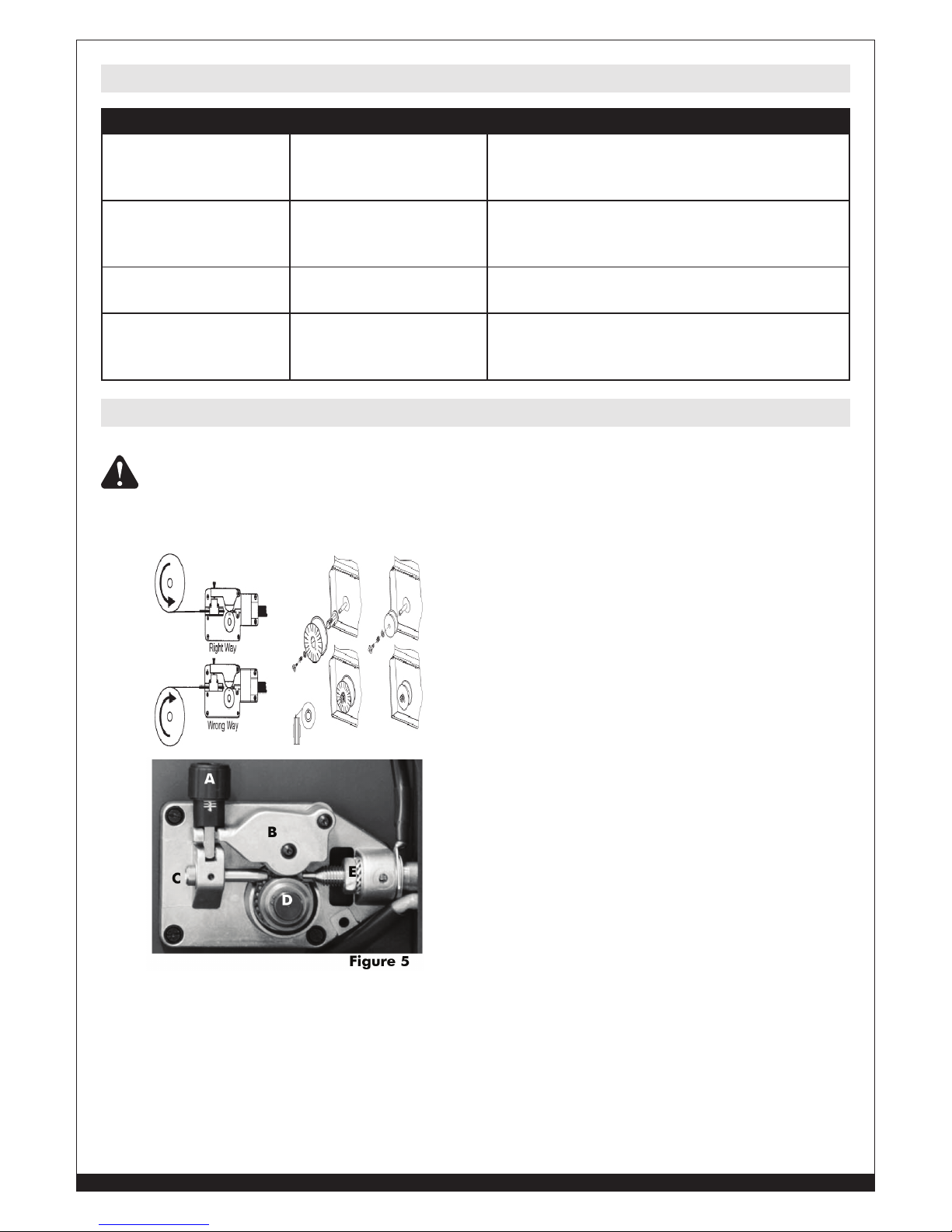
• Loosen and lower the plastic knob (Fig.5) (A). Open
the pressure arm (B) of the feeder.
• Disconnect the wire from the edge of the wire spool
being careful to keep tension on the end of the
wire. Cut off a short section of the end of the wire to
insure a straight end. Insert the the straight end into
the wire inlet guide (C) past the wire feed roll and
into the wire liner. Lower pressure arm (B) and lift
pressure adjustment knob (A) into place. Connect
the input power cord and turn on the welder. Press the torch trigger and observe the wire
feeding into the torch liner. Adjust the pressure on the wire with knob (A) to insure smooth
feeding without slippage. Do not over tighten the pressure adjustment as it may damage
the motor. Close the welder side panel. Remove the nozzle and contact tip from the welding
torch. Straighten the torch cable to remove any coils or kinks. Squeeze and hold the torch
trigger until the wire appears at the end of the torch neck. Turn off the welder and install the
contact tip and nozzle.
14
WWW.FORNEYIND.COM
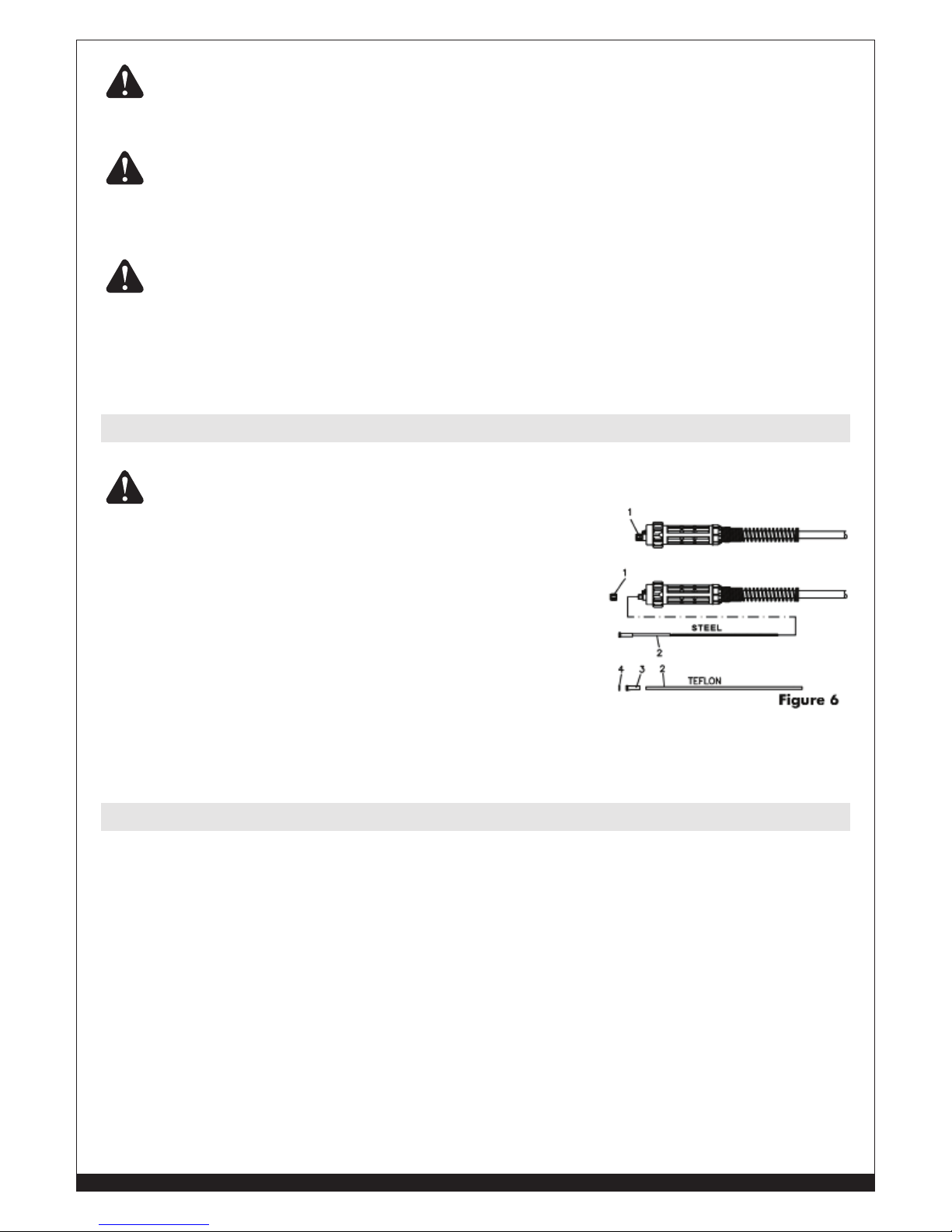
WARNING: Keep the torch straight when feeding a new wire through the liner. Make sure
the wire is cut cleanly (no burrs or angles) and that at least 1/2” from the end is straight (no
curves). Failure to follow these instructions could cause damage to the liner.
KEEP THE TORCH STRAIGHT. WHEN FEEDING A NEW WIRE THROUGH THE
LINER, MAKE SURE THE WIRE IS CUT CLEANLY (NO BURRS OR ANGLES) AND
THAT AT LEAST 1” FROM THE END IS STRAIGHT (NO CURVES). FAILURE TO
FOLLOW THESE INSTRUCTIONS COULD CAUSE DAMAGE TO THE LINER.
WHEN CHECKING THE CORRECT EXIT OF THE WIRE FROM THE TORCH DO
NOT BRING YOUR FACE NEAR THE TORCH. YOU MAY RUN THE RISK OF
BEING WOUNDED BY THE OUTGOING WIRE. DO NOT BRING YOUR FINGERS
CLOSE TO THE FEEDING MECHANISM WHEN WORKING! THE ROLLS, WHEN
MOVING, MAY CRUSH FINGERS. PERIODICALLY CHECK THE ROLLS. REPLACE
THEM WHEN THEY ARE WORN AND COMPROMISE THE REGULAR FEEDING OF
THE WIRE.
Replacing the Wire Liner
BEFORE PERFORMING THIS PROCEDURE, BE SURE THE GAS SUPPLY LINE AND
INPUT POWER CABLE ARE DISCONNECTED.
• Disconnect the torch from the machine.
• Place it on a flat surface and carefully remove the brass nut.
• Pull the liner out of the hose.
• Install the new liner and mount the brass nut again.
In case you are replacing a Teflon or graphite wire liner, follow these
instructions:
• Install the new liner and insert the wire liner collet and the
O ring.
• Mount the brass nut.
• Cut the wire liner close to the brass nut NOTE: The length of the new wire liner must be the
same as the liner you have just pulled out of the hose.
• Connect the torch to the machine and install the wire into the feeding system.
How to Choose the Wire Liner for Direct and Euro Connect Torches
There are basically two types of wire liners: Steel and Teflon. Steel wire liners can be coated or noncoated. Coated wire liners are used for air-cooled torches. Teflon wire liners are recommended for
aluminum welding as they allow smooth feeding of the wire.
15
WWW.FORNEYIND.COM
• Connect the ground cable to the positive terminal of the
Polarity Change Board inside the spool compartment.
• Connect the working cable to the negative terminal of
Polarity Change Board inside the spool compartment.
• Connect the ground cable to the negative terminal on the
Polarity Change Board inside the spool compartment
• Connect the working cable to the positive terminal of the
Polarity Change Board inside the spool compartment.
The machine needs to be set up as follows:
• 100% ARGON as welding protective gas.
• Ensure that your torch is set up for aluminum welding:
1. The length of the torch cable should not exceed 10’ (it is advisable not to use longer
torches).
2. Install a Teflon wire liner. Follow the instructions for changing the renewing of the wire
liner.
3. Use contact tips that are suitable for aluminum wire and make sure that the diameter of
the contact tip hole corresponds to the wire diameter that is going to be used.
• Ensure that drive rolls are suitable for aluminum wire.
Arrangement For Welding With a Spool Gun
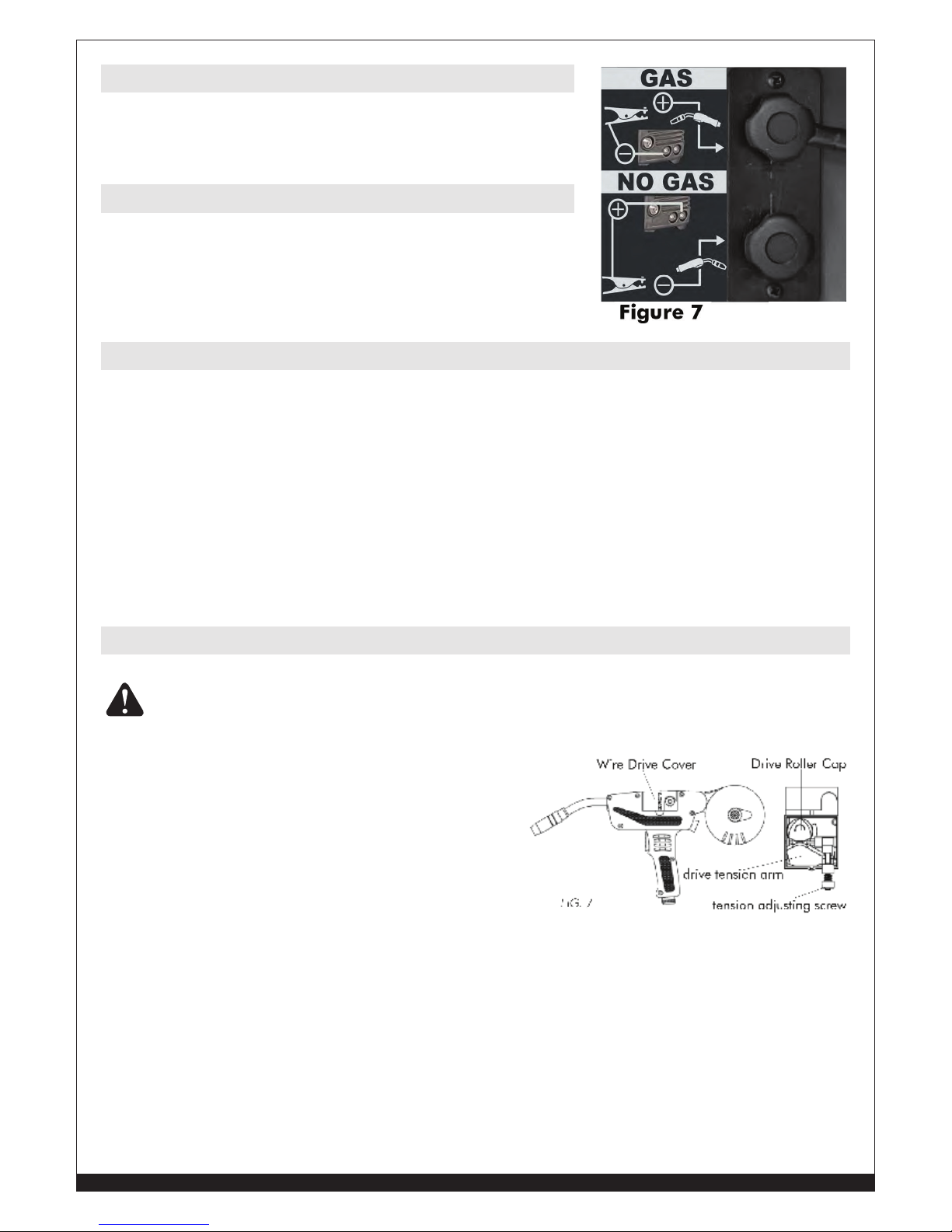
WARNING: Electric shock can kill! Always turn the POWER switch OFF and unplug the power
cord from the AC power source before installing wire.
Before installing any welding wire into the unit,
the appropriate drive roll must be placed into position
on the wire drive mechanism. Ensure the groove is the
proper shape and size for the wire being used. Adjust
the drive roll according to the following steps:
1. Open the wire drive cover on the spool gun.
2. Remove the drive tension by loosening the
tension adjusting screw and lifting the drive
tension adjustor up, away from the drive
tension arm. Pull the drive tension arm away from the drive roller.
3. If needed, loosen the tension adjusting screw on the drive tension arm. Pull the drive tension
arm up to allow access to the drive roll within the wire drive system. Rotate the black drive
roll cap counterclockwise and remove it to reveal the metallic drive roll. Pull the drive roll
off its shaft. NOTE: The drive roll has two wire size (.030” and .035”) grooves built into it.
Ensure the corresponding groove and wire size are used. Replace the drive roll onto its shaft
and drive roll cap onto the drive roll.
4. Find the side of the drive roller that is stamped with the same wire diameter as that of the
wire being installed. Push the drive roller onto the drive roller shaft, with the side stamped
with the desired wire diameter facing you.
5. Reinstall the drive roller cap and lock in place by turning it clockwise.
Fluxcore Wire Welding, “FCAW”
MIG Welding, “GMAW”
Aluminum Welding
16
WWW.FORNEYIND.COM
6. Remove the nozzle and contact tip from the end of the gun assembly.
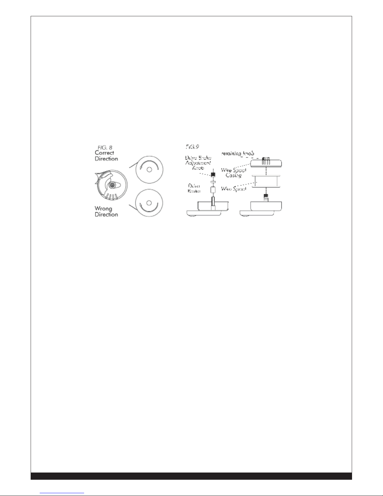
7. Open the wire spool casing, located at the rear of the spool gun, by turning the retaining
knob counterclockwise.
8. Unwrap the spool of wire and find the end of the wire.
9. After checking to make sure that your welder is disconnected from the AC power source, free
the leading end of the wire from the spool, but do not let go of it until told to do so, or the
wire will unspool itself.
10. Using a wire cutter, cut off the bent portion at the end of the wire so that you are left with a
straight section of wire.
11. Unroll about 6” of welding wire from the wire spool.
12. Insert the leading end of the wire into the inlet guide tube (located in the Wire Spool
Casing). Then push it across the drive roller and into the gun assembly about 6”.
13. Line the wire up in the appropriate top groove of the drive roller, then push the drive tension
arm against the drive roller.
14. Flip the quick release drive tensioner back into position on the drive tensioner arm.
15. Tighten (turn clockwise) the drive tension adjusting knob until the tension roller is applying
enough force on the wire to prevent it from slipping out of the drive assembly.
16. Let go of the wire.
17. The welding wire should always come off the top of the spool into the drive mechanism.
NOTE: The purpose of the drive brake is to cause the spool of wire to stop turning at nearly
the same moment that wire feeding stops.
18. Set the Drive Brake tension. NOTE: It is necessary to release the Drive Tensioner Arm while
you are setting the Drive Brake Tension. Make sure you return the Drive Tension Arm to its
locked position after adjusting the Drive Brake Tension.
a) With one hand, turn the wire spool counterclockwise. This will cause the wire to feed
through the gun assembly continue turning it while adjusting the tension on the spool.
b) With your free hand, tighten (turn clockwise) the drive brake adjustment knob.
c) Stop tightening when drag is felt on the wire spool that you are turning. Then stop hand-
turning the wire spool. NOTE: If too much tension is applied to the wire spool, the wire
will slip on the drive roller or will not be able to feed at all. If too little tension is applied,
the spool of wire will want to unspool itself. Readjust the drive brake tension as necessary
to correct for either problem.
19. Trim the wire which is sticking out the end of the spool gun to about 1/2” in length.
20. Select a contact tip stamped with the same diameter as the wire being used.
21. Slide the contact tip over the wire protruding from the end of the gun.Thread the contact tip
into the end of the gun and hand-tighten securely.
22. Install the nozzle on the gun assembly. For best results, coat the inside of the nozzle with
anti-stick spray or gel.
23. Cut off the excess wire that extends past the end of the nozzle.
24. Replace the wire spool casing cover and tighten adjustment knob by turning it clockwise.
25.
Connect the welder power cord to the AC power source. Turn the welder ON. Set the VOLTAGE switch.

17
WWW.FORNEYIND.COM
WARNING: Arc flash can injure eyes! To reduce the risk of arc flash, make certain that the
wire coming out of the end of the gun does not come in contact with the work piece, ground
clamp or any grounded material during the drive tension setting process or arcing will occur.
1. Open the wire drive cover on the spool gun
2. Pull the trigger on the gun.
3. Turn the drive tension adjustment knob clockwise, increasing the drive tension until the wire
seems to feed smoothly without slipping.
4. Close the wire drive cover on the spool gun.
5. When set correctly, there should be no slippage between the wire and the drive roller under
normal conditions.
Before you begin welding, you may want to adjust the position of the spool so it is most
comfortable for
you. There are three positions to choose from. To change the position of the spool:
1. With a flat tipped screwdriver, loosen the screw which connects the spool casing to the gun.
2. Pull the casing far enough away from the gun to allow the casing to rotate.
3. Rotate the casing to one of the three available positions, making sure that the grooves on the
gun are aligned with the grooves on the casing.
4. Push the casing and the gun back together.
5. With a flat tipped screwdriver, tighten the screw which connects the spool casing to the gun.
Your new single phase inverter multi-function welder offers three welding functions in the same
power source. These functions can be selected with knob (6) on the front panel of the unit.
Fluxcore Wire Welding, “FCAW” and MIG Welding, “GMAW”
This welder offers the choice to weld in manual or synergic mode.
1. Manual Mode: The operator is required to set both the wire speed (Left Knob) and the
welding voltage (Right Knob).
2. Synergic Mode: As in manual function, the operator is required to set both the wire speed
(Left Knob) and the welding voltage (Right Knob). Once both parameters are set, the
synergic function allows the operator to move to different thickness of material to be welded
by simply adjusting the Left Knob. The correct voltage will be automatically set by the
machine’s software.
Stick Welding, “SMAW”
Both rutile and basic electrodes can be welded. Welding current is adjusted using the Left Knob.
TIG Welding, “GTAW”
In the TIG position, a TIG torch with a trigger control and a gas valve in the handle is required.
The gas valve must be opened manually before welding and closed manually when welding is
completed. The arc is activated using the torch trigger. Using the Left Knob welding current can
adjusted.
Setting the Wire Drive Tension
Adjusting the Spool Position
Operation
Description
18
WWW.FORNEYIND.COM
2T: Press the torch trigger to weld. Welding continues until the trigger is released.
4T: Press the torch trigger and immediately release the trigger, welding will start and continue
until the torch trigger is pressed and released a second time. The 4T function is useful when
doing long welds and in some automatic welding operations where the torch may be mounted in
a fixture.
CAT# 324
Forney Industries, Fort Collins, CO USA
MULTI-PROCESS WELDER
230V – 50 AMP, 115V – 15 AMP INPUT
PROCESS SELECTOR
M
A
N
2
T
S
Y
N
2
T
M
A
N
4
T
S
Y
N
4
T
S
T
I
C
K
T
I
G
M
I
G
M
O
D
E
S
STICK
(HOT START)
TIG (N/A)
MIG MAN (V)
MIG SYN
(THICKNESS)
STICK (A)
TIG (A)
MIG MAN
(WFS)
MIG SYN
(WFS)
14 52 3
6
7
8
9
11
10
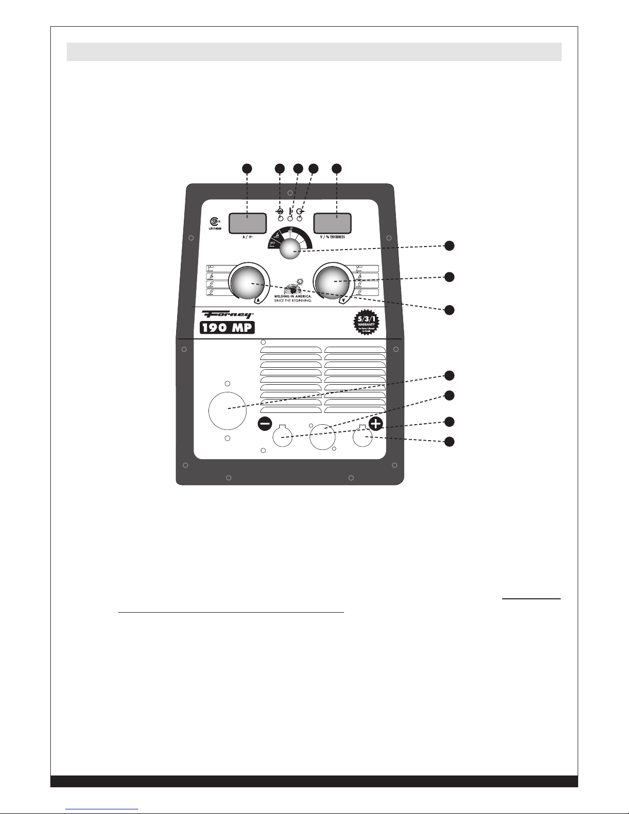
12
1. POWER SWITCH INDICATOR: This green LED lights when the welding machine is ON
and is ready to work. A steady green LED indicates the welder is connected to power supply.
In the event of an overvoltage supply the green LED blinks and the red LED (3) is ON.
2. THERMAL OVERLOAD INDICATOR: If the yellow LED is ON it indicates that the welder
has overheated and the machine has automatically shut down. This may be a result of
having exceeded the welders duty cycle or that normal cooling air flow has been interrupted.
Check to confirm that the cooling fan is running and that air flow is not blocked. Do not turn
off the welder as this will stop the cooling fan. When the welder has cooled sufficiently the
yellow LED will go out and the welder is ready to weld.
3. ALARM INDICATOR: This red LED lights when there is a working abnormality such as an
over voltage supply.
4. LEFT DISPLAY: During welding it displays the actual value of the output current (AMP).
When the machine is not welding, (no load), the display shows the value of the parameter
selected with the Left Knob (8):
a. In STICK, “SMAW”and TIG, “GTAW” Mode it shows the selected current value. If Remote
is selected with switch (20) for TIG Welding, “GTAW” with a foot control, the display will
alternate between “ReC” (to indicate remote control), and the selected current. In this case
the current is adjusted using the foot control.
Welder Controls

19
WWW.FORNEYIND.COM
b. In MIG, “GMAW” Manual Mode (2T/4T), the display shows the selected wire speed
from 1 (minimum wire feeder speed) to 80 (maximum speed). If Remote is selected with
switch (20), the display will alternate between “SPE” (to indicate spool gun external) and
the selected wire speed which is adjusted with a potentiometer located on the spool gun
handle.
c. In MIG, “GMAW” Synergic Mode (2T/4T), the display shows the selected wire speed
from 1 (minimum wire feeder speed) to 80 (maximum speed). If Remote is selected with
switch (20), the display will alternate between “SPE” (to indicate spool gun external) and
the selected wire speed which is adjusted with a potentiometer located on the spool gun
handle.
5. RIGHT DISPLAY: During welding it displays the actual arc voltage. When the machine is
not welding (no load) it displays the value of the parameter adjusted with the Right Knob (7):
a. In STICK, “SMAW”Mode it displays the Hot Start over-current value expressed as a
percentage of the base welding current selected with the left knob (8). The over current
value is variable from 0 to 50% of the base current. Maximum Hot start value of 50%
can be adjusted up to 55 Amp of welding current. On the display the value of Hot Start
is shown as “H” and the value of the over current in %.
b. In TIG, “GTAW” Mode the display is not active.
c. In MIG, “GMAW” Manual Mode (2T/4T) it displays the selected arc voltage from
10V to 24V.
d. In MIG, “GMAW” Synergic Mode (2T/4T) it displays the value of the selected voltage
expressed as a percentage of the maximum available voltage.
6. SELECTOR SWITCH FOR THE WELDING MODES SELECTION: STICK, “SMAW” -
TIG, “GTAW” - MIG, “GMAW” manual 2T, manual 4T, Syn 2T, Syn 4T.
7. RIGHT KNOB: It is used to adjust the following welding parameters:
a. In STICK, “SMAW”Mode it adjusts the over-current value of the electric arc (Hot Start),
variable from 0 to 50% on the current value adjusted with the Left Knob (8).
b. In TIG, “GTAW” Mode is not active.
c.
In MIG, “GMAW” Manual Mode (2T/4T) it adjusts arc voltage value (no load) from
10V to 24V.
d. In MIG, “GMAW” Synergic Mode (2T/4T) it adjusts the % of welding power available
(depending on the input voltage) variable from 0 to 80% (maximum power).
8. LEFT KNOB: It is used to adjust the following welding parameters:
a. In STICK, “SMAW”Mode it adjusts the current value from a minimum of 20Amp to a
maximum of 80 Amp. If Remote is selected with switch (20) the left knob is not active.
b. In TIG, “GTAW” Mode, it adjusts the current value from a minimum of 5 Amp to a
maximum of 100Amp. If Remote is selected with switch (20) the Left knob is not active.
c. In MIG, “GMAW” Manual Mode (2T/4T) it adjusts the wire speed from 1 (minimum wire
feeder speed) to 80 (maximum speed). If Remote is selected with switch (20) the Left knob
is not active.
d. In MIG, “GMAW” Synergic Mode (2T/4T) it adjusts the wire speed from 1 (minimum
wire feeder speed) to 80 (maximum speed). If Remote is selected with switch (20) the Left
knob is not active.
9. NEGATIVE DINSE SOCKET:
a. In STICK Welding, “SMAW” for the connection of the ground cable connector (check
for correct polarity for the electrode you are going to use, refer to the information on its
box);
b. In TIG Welding, “GTAW” for the TIG torch cable connection (Torch trigger connection
must be connected to the 7 pin connector – 12 -)
20
WWW.FORNEYIND.COM
c. In MIG Welding, “GMAW” (with gas) for the connection of the ground cable connector
10. POSITIVE DINSE SOCKET:
a. In STICK Welding, “SMAW”, for the connection of the ground cable connector (check
for correct polarity for the electrode you are going to use, refer to the information on its
box);
b. In FLUXCORE WIRE Welding, “FCAW”, for the connection of the ground cable connector.
11. EURO CONNECT FOR ATTACHING THE MIG TORCH CABLE. In FLUXCORE WIRE
Welding, “FCAW”, change the polarity of the Euro socket using the terminals on the Polarity
Change Board located inside the wire spool compartment above the wire feeder -19-). To
attach the Spool Gun, remove the standard MIG torch from the Euro Connect and connect
the Spool Gun. Also connect the Spool gun control lead to the seven pin connector (12) on
the front of the cabinet and switch the Local / Remote switch (20) to the Remote position.
12. 7 PIN CONNECTOR:
a. In STICK, “SMAW”Mode when Remote is selected with switch (20) for connecting the foot
remote control;
b. In TIG, “GTAW” Mode when Local is selected with switch (20), for connecting the TIG
torch trigger control cable;
c. In TIG, “GTAW” Mode when Remote is selected with switch (20) for connecting the
foot pedal remote control; in this case the TIG torch trigger control cable has to be
disconnected;
d. In MIG Welding, “GMAW”, Manual and Synergic when Remote is selected with switch
(20), for connecting the Spool gun torch 7 pin male connector.
13. INPUT POWER CABLE (BACK OF MACHINE)
14. ON/OFF SWITCH (BACK OF MACHINE)
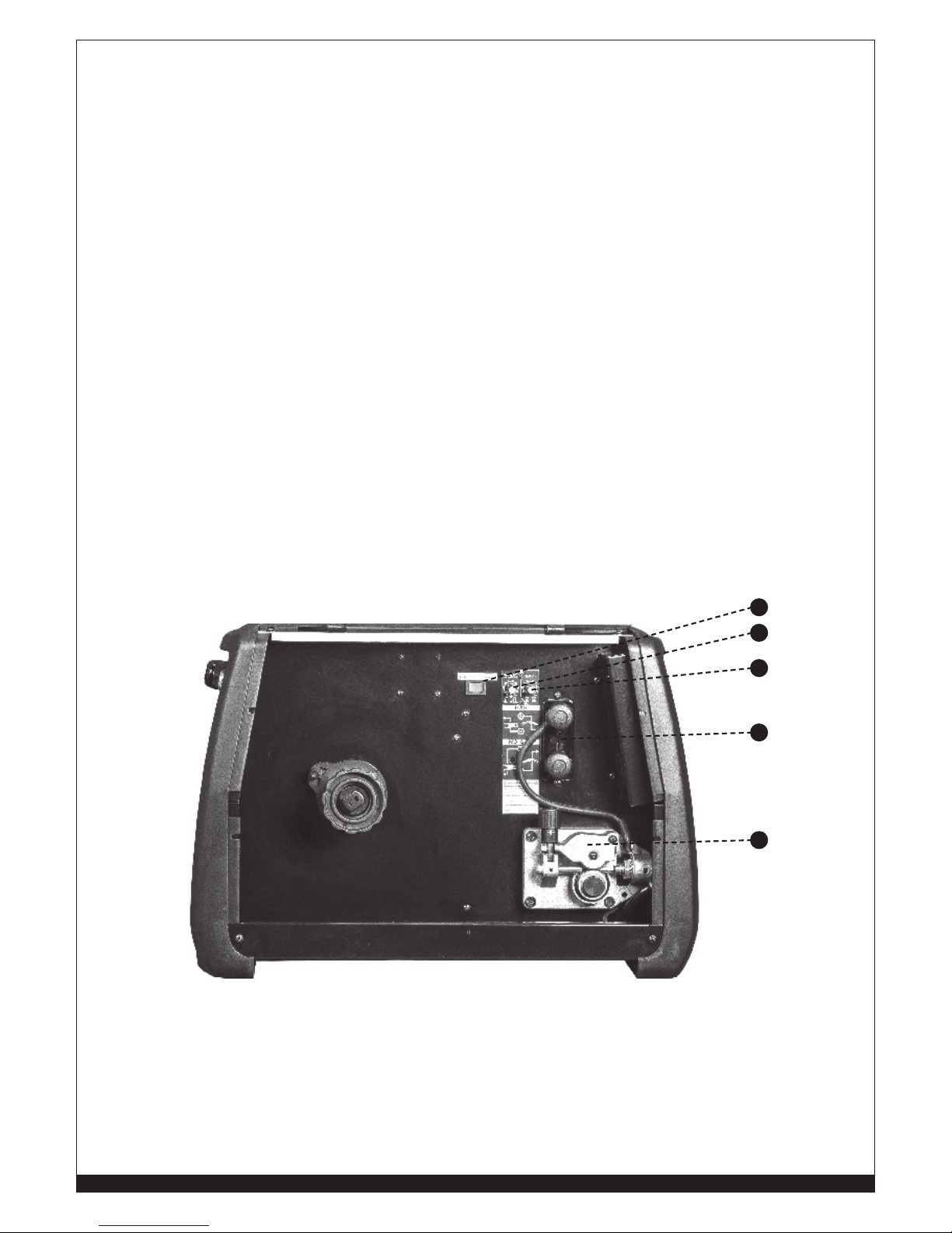
16
19
17
18
15
FIGURE 3
15. 2 ROLL ALUMINUM WIRE FEEDER
16. SLOPE UP TIME REGULATION POTENTIOMETER
17. BURN BACK TIME REGULATION POTENTIOMETER (B.B.T.)
18. POLARITY CHANGE TERMINALS FOR THE EURO SOCKET:
a. Positive polarity for MIG Welding, “GMAW”;
b. Negative polarity for FLUXCORE WIRE Welding, “FCAW”
21
WWW.FORNEYIND.COM
19. LOCAL / REMOTE SWITCH:
a. Local: when selected all welding parameters have to be adjusted using knobs 7 and 8 on
the front control panel
b. Remote: when selected Left Knob (8) is not active. In STICK Welding, “SMAW” and TIG
Welding, “GTAW” Mode current is adjustable using the foot pedal. In MIG Welding,
GMAW” Mode the wire speed is adjustable using the potentiometer on the Spool Gun
torch.
WARNING: If the duty cycle of the welder is exceeded, a thermostat will automatically cut
the power to prevent the machine from overheating. If this should happen do not unplug the
machine while it cools down. The thermostat will automatically reset itself and you can continue
welding. The thermostat is a protective safety device and no harm will normally be done to the
welder unless it is frequently over-loaded, in which case it may eventually become damaged.
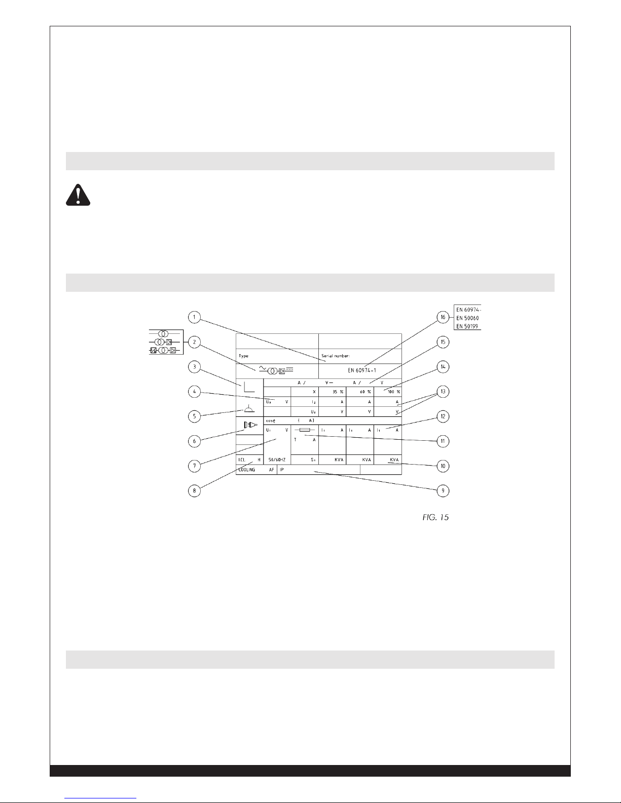
1. Serial number of the unit
2. Welder model
3. Type of characteristic
4. Min. - Max rated No Load Voltage
5. Type of welding
6. Symbol for the main supply and no. of phases
7. Rated value of the supply voltage
8. Code letter for degree of insulation
9. Protection degree
10. Power
11. Size of the necessary main fuse
12. Supply current
13. Welding supply and voltage
14. Power Factor
15. Control range (current / voltage)
16. Reference standard
• Attach the ground clamp to the bare metal to be welded, making sure of good contact;
• Make sure that the wire-roller groove in the roller corresponds to the diameter of the wire
being used.
• Plug the machine into a suitable outlet.
•
Completely open the gas cylinder valve. Adjust the gas pressure regulator to the correct
flow rate.
Thermal Overload Protection
Technical Data Information Guide
Welding Preparation

22
WWW.FORNEYIND.COM
Some experience is required to adjust and use a MIG welder. In MIG welding two parameters are
fundamental: the welding voltage and the wire speed. The resulting welding current is a result of these
two settings.
• Set the voltage and wire feed controls to positions suitable for the thickness of the material
to be welded. Welding current varies in relationship to wire feed speed. For low welding
current output, the wire feed speed potentiometer should be set at the low end of the wire
feed speed scale. Turning the wire feed speed control potentiometer clockwise will result
in increased wire feed speed and welding current. Welding voltage is adjusted to match
the wire feed speed (welding current). Progressively select higher voltage positions while
increasing wire speed.
Increasing welding voltage leads to a longer arc (without substantially affecting the current).
Conversely, a decreased welding voltage results in a shorter arc (the current again is not substancially
changed). A change in wire diameter results in changed parameters. A smaller diameter wire
requires an increase in wire feed speed to reach the same current. If certain limits are exceeded, a
satisfactory weld cannot be obtained. These are:
A) Feeding wire too fast (too high with regard to the welding voltage) results in pulsing within
the torch. This is because the wire electrode dips into the puddle and cannot be melted off fast
enough.
B) Setting welding voltage to high (too high with regard to the wire feed speed), will result in
excessive and unstable arc. Increase the voltage even higher and the contact tip will burn.
C) Excessive wire speed can be corrected through the arc voltage increase. The limit of this
adjustment depends on the thickness of the material to be welded (a certain limit exceeded
will result in burn through).
Place the torch on the joint you want to weld: the angle between the torch and the nozzle should be
around 45°. The distance between the torch and the work piece should be 5-1/2”. Lower the face
shield and press the torch trigger to start the arc. When the arc has struck, move the nozzle slowly
from left to right along the joint. Adjust the wire feed speed until the arc makes a “crisp” sound
(experience will help you to recognize the right sound).
This welder can work with Aluminum wire .030” (0.8mm) diameter, solid steel wire .023”- .035”
(0.6-0.9mm) diameter and stainless steel wire .030”-.035” (0.8-0.9mm) diameter (MIG Welding,
“GMAW”) and with flux core wires 0.9mm diameter (.035”) (FLUXCORE WIRE Welding, “FCAW”).
According to the material to be welded and to the wire you are going to use, select the shielding gas.
The table below can give you some useful indications:
MATERIAL TO WELD GAS CYLINDER WIRE
Mild Steel Argon + CO2
Cylinder or CO2 Cylinder
Copper coated mild steel wire spool. For
FLUXCORE WIRE Welding, “FCAW” use
flux-cored wire spool
Stainless Steel Argon Cylinder Stainless Steel wire spool
Aluminum Argon Cylinder Aluminum wire spool
Factors to Consider for Best Welding Results
Welding Wire Selection
Gas Selection
23
WWW.FORNEYIND.COM
• Select the STICK, “SMAW”function with the Selector Switch (6) on the front panel.
• Check the electrode packaging to determine the recommended polarity and connect the
Electrode holder and ground clamp to the plus and minus Dinse sockets accordingly.
• Switch the unit ON thru the ON/OFF switch (14).
• If “Local (20)” is selected set the welding current with the Left Knob (8) on the front panel and
the strike over-current value of the electric arc (Hot Start) with the Right Knob (7)
• If “Remote (20)” is selected set the welding current using the foot pedal which has to be
connected to the 7-pin connector (12). The over-current value of the electric arc (Hot Start)
with the Right Knob (7).
Adjustable Welding current:
120V input voltage: Min 20 Amp - Max 80 Amp
230V input voltage: Min 20Amp - Max 170Amp
230V INPUT VOLTAGE REQUIRED
Regulation Knob
Left Knob Left Knob Left Knob Left Knob Left Knob
Mild Steel
6013 30-35 40-70 70-95 100-135 145-160
7018 30-35 40-70 70-110 90-160 130-160
Stainless Steel
316 30-35 40-70 40-80 60-110 90-150
MATERIAL
(Wire)
ELECTRODE TYPE
ELECTRODE DIAMETER
1/16” (1.6 mm) .0787” (2 mm) 3/32” (2.4 mm) 1/8” (3 mm) 5/32” (4 mm)
190 MP STICK SET-UP CHART
Setting up the Equipment for TIG Welding (GTAW) with no Foot Control:
• Select the TIG function on the control panel with knob (6).
• Choose LOCAL with switch (20).
• Connect the TIG torch cable to the negative Dinse socket (9) of the welder.
• Connect the ground cable connector to the positive Dinse socket (10) of the welder.
• Connect the TIG torch control cable to the 7 pin connector (12).
• Connect the TIG torch gas line to the gas regulator (argon gas only).
THE GAS FLOW IS MANUALLY CONTROLLED WITH THE KNOB ON THE TIG
TORCH. USE INERT GAS (ARGON) ONLY.
Setting up the Equipment for TIG Welding (GTAW) using a Foot Control:
• Switch the unit on thru the ON/OFF switch (14).
• Select the TIG function on the control panel with knob (6).
• Choose REMOTE with switch (20).
• Connect the TIG torch cable to the negative Dinse socket (9) of the welder.
• Connect the ground cable connector to the positive Dinse socket (10) of the welder.
• Connect the Foot Control cable to the 7 pin connector (12)
• Connect the TIG torch gas line to the gas regulator (argon gas only).
TURN ON GAS AT THE GAS REGULATOR, THEN OPEN THE VALVE ON THE TORCH
HANDLE AND CHECK FOR GAS FLOW.
Setup for Stick Welding (SMAW)
Setup for TIG Welding (GTAW) with Lift Arc

24
WWW.FORNEYIND.COM
Starting the Arc with Lift Start:
• Fix the tungsten electrode so that it protrudes approximately ¼ inch from the torch nozzle.
• Position the torch so that the tungsten electrode is in contact with the work piece at a 45
degree angle.
• Press the torch trigger or the foot control and then lift the tungsten electrode away from the
work piece.
REMEMBER TO TURN OFF THE GAS IMMEDIATELY AFTER YOU FINISH WELDING.
230V INPUT VOLTAGE REQUIRED
Regulation Knob
Left Knob Left Knob Left Knob Left Knob Left Knob Left Knob
Mild
Steel
Stainless
Steel
Mild
Steel
Stainless
Steel
Mild
Steel
Stainless
Steel
Mild
Steel
Stainless
Steel
Mild
Steel
Stainless
Steel
Mild
Steel
Stainless
Steel
Mild Steel
Solid Wire
100% Argon
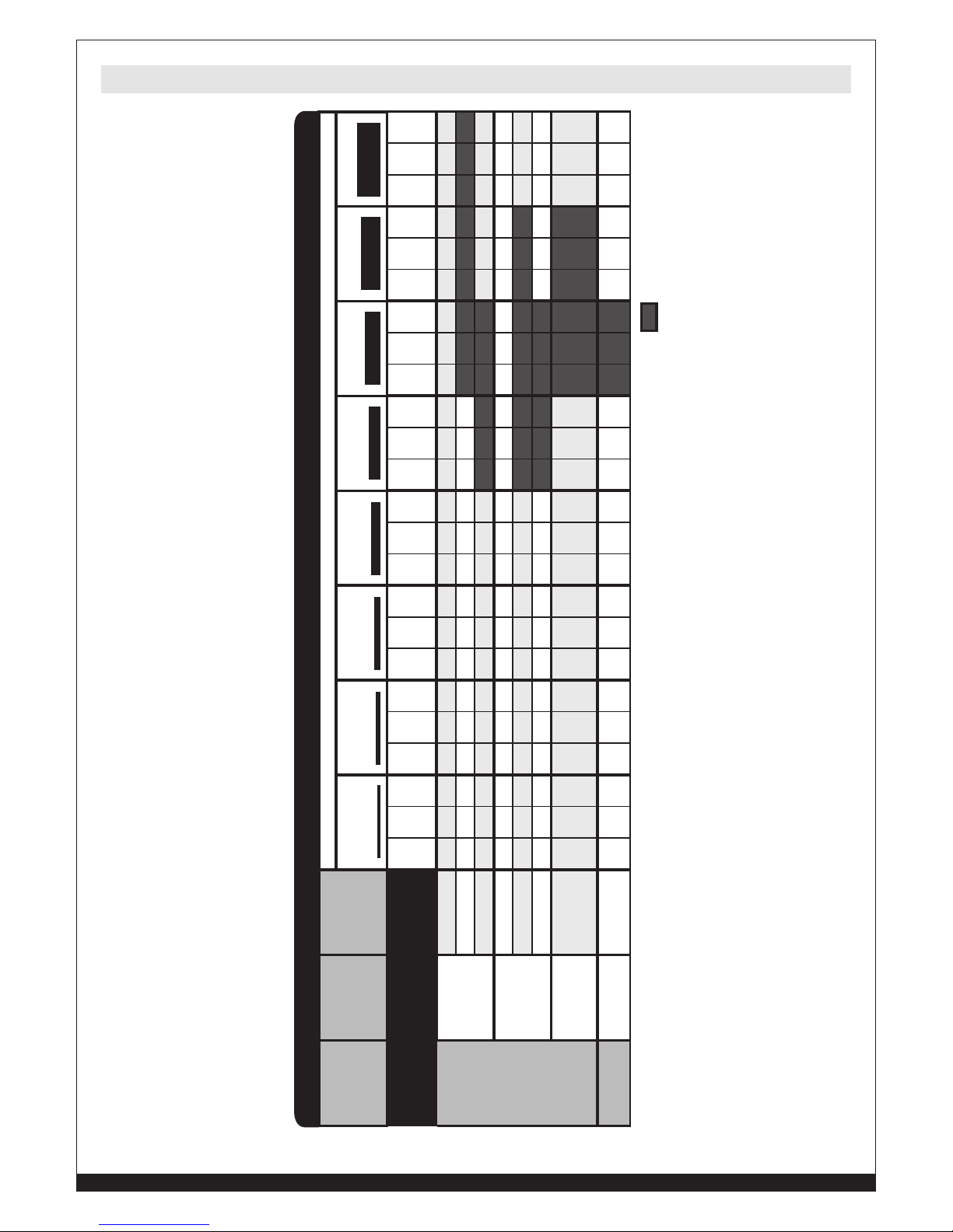
.040” (1.0 mm) 35-50 20-35 45-60 30-55 - - - 1/16” (1.6 mm) - - - - 60-90 40-70 80-100 65-100 - - - 3/32” (2.4 mm) - - - - - - - - 15-165 100-150 - -
5/32” (4mm) - - - - - - - - - - 160-180 135-180
MATERIAL
(Wire)
GAS
TUNGSTEN
ELECTRODE
ø
MATERIAL THICKNESS
22 Gauge
.0315” (.8 mm)
18 Gauge
.0236” (1.2 mm)
16 Gauge
1/16” (1.6 mm)
1/8” (3 mm) 3/16” (5 mm) 1/4” (6 mm)
190 MP TIG SET-UP CHART
Before connecting the unit to the mains, verify that all the accessories are correctly installed and
mounted for electric welding (torch, wire spool etc ...).
• Select Manual MIG (2T or 4T) Welding function with the Selector Switch (6) on the front panel.
Select either the 2-Step or 4-Step function of the torch trigger. 2-Step trigger turns welding
arc ON and OFF each time the trigger is pressed and released. Welding current is ON when
the torch trigger is pressed. 4-Step mode permits the operator to weld with the torch trigger
released. To start welding press the torch trigger and release. To stop welding press and
release the torch trigger. 4-Step mode helps the operator make long welds with less fatigue.
• Switch the unit ON thru the ON/OFF switch (14) on the back side of the unit.
• Press the torch trigger to load the wire.
• Set the welding parameters
1. Wire feed speed: Welding Current (AMPS) If “Local (20)” is selected use Left Knob (8) to
adjust the wire speed from 1 to 100 (maximum speed). When the machine is supplied at
120V the maximum value is 80. If “Remote (20)” is selected use the potentiometer of the
Spool Gun torch to adjust wire speed.
2. Arc voltage: use the Right Knob to adjust arc voltage value (no load) from 10V to 26V.
When the machines is supplies at 120V the maximum value adjustable is 24V.
• Bring the torch close to the work piece and press the trigger
1. Wire feeder Slope-Up Time (Min. to Max. speed transition time), adjustable with the
potentiometer located inside the access panel (17).
2. At the end of the Slope-Up Time, the wire feed speed reaches the value adjusted with the
Left knob (8).
• To stop welding, release the trigger. The arc stays ON accordingly to the set B.B.T. (Burn
back time). B.B.T. is the amount of time that the weld output continues after the wire stops
feeding. It prevents the wire from sticking in the puddle and prepares the end of the wire for
the following arc start.
MIG, GMAW, Fluxcore Wire (FCAW) Manual Welding

25
WWW.FORNEYIND.COM
• Select MIG Synergy (2T or 4T) Welding function thru the Selector Switch (6) on the front
panel. The 2-Step / 4-Step change the function of the gun’s trigger. 2-Step trigger turns
welding arc ON and OFF each time the trigger is pressed. Welding current is ON when
the torch trigger is pressed. 4-Step mode permits the operator to weld with the torch trigger
released. To stop welding press and release the torch trigger. 4-Step mode helps the operator
make long welds.
• MIG Synergy functions permits the operator to move to different materials thickness to be
welded simply adjusting the Left Knob (8). The correct voltage will be set automatically by the
machine’s software. In order to permit the software to set the correct voltage the operator is
asked to set the “starting welding parameter” as suggested on the setting chart.In fact a wire
speed value and voltage value have to be set in order to activate the synergy mode.
• Switch the unit ON thru the ON/OFF switch (14) on the back side of the unit.
• Press the torch trigger to load the wire and check that the gas is flowing from the welding
torch.
• Set the “starting welding parameters”:
1. Wire feed speed: A) If “Local (20)” is selected use Left Knob (8) to adjust the wire speed
from 1 to 100 (maximum speed). If “Remote (20)” is selected use the potentiometer of the
Spool Gun torch to adjust wire speed.
2. Arc length: use the Right Knob to adjust arc length value from 0 to 100. With 120V input
voltage maximum value is 80”.
3. Once both parameters are set the Synergic Mode allows the operator to weld different
thickness of the same material simply adjusting the Left Knob (8).
• Bring the torch close to the work piece and press the trigger.
1. Wire feeder Slope-Up Time (Min. to Max. speed transition time), adjustable with the
potentiometer located inside the access panel (17).
2. At the end of the the Slope-Up Time, the wire feed speed reaches the value adjusted with
the Left knob (8).
• To stop welding, release the trigger. The arc stays ON accordingly to the set B.B.T. (Burn
back time). B.B.T. is the amount of time that the weld output continues after the wire stops
feeding. It prevents the wire from sticking in the puddle and prepares the end of the wire for
the following arc start.
MIG, GMAW, Fluxcore Wire (FCAW) Synergic Welding
26
WWW.FORNEYIND.COM
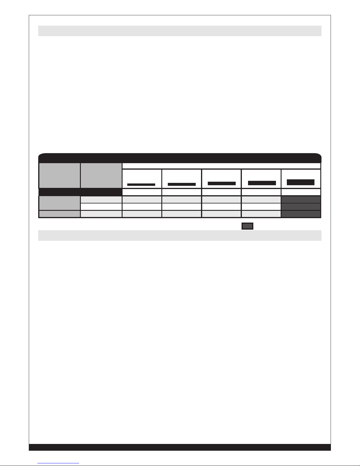
230V INPUT VOLTAGE REQUIRED
Regulation Knob
Left
Knob
Right
Knob
MIG
Man
Right
Knob
MIG
Syn
Left
Knob
Right
Knob
MIG
Man
Right
Knob
MIG
Syn
Left
Knob
Right
Knob
MIG
Man
Right
Knob
MIG
Syn
Left
Knob
Right
Knob
MIG
Man
Right
Knob
MIG
Syn
Left
Knob
Right
Knob
MIG
Man
Right
Knob
MIG
Syn
Left
Knob
Right
Knob
MIG
Man
Right
Knob
MIG
Syn
Left
Knob
Right
Knob
MIG
Man
Right
Knob
MIG
Syn
Left
Knob
Right
Knob
MIG
Man
Right
Knob
MIG
Syn
Mild Steel
Solid Wire
75% Ar + 25%
CO
2
(ER70S-6)
.023” (0.6 mm) 25 17.8 82 42 18.5 69 51 19.5 66 71 20.6 52 78 22 52 - - - - - - - - -
.030” (0.8 mm) 22 15.1 65 33 16.7 65 44 18 65 55 19.7 65 60 20.7 65 65 22.2 65 75 23 65 80 23.7 65
.035” (0.9 mm) 22 15.5 68 28 16.4 68 33 17.1 68 44 18.7 68 55 21.3 75 60 22.1 76 - - - - - -
Solid Wire
100% CO
2
(ER70S-6)
.023” (0.6 mm) 37 19.3 80 48 19.9 73 59 21.2 70 85 23.7 59 74 24.6 55 - - - - - - - - -
.030” (0.8 mm) 24 15.8 69 33 17.5 69 44 18.9 69 60 21.9 69 75 23.6 69 85 24.9 69 90 25.8 69 - - -
.035” (0.9 mm) - - - 19 18.2 92 30 19.7 90 38 21.1 93 46 22.7 96 55 24 97 - - - - - -
Flux Core Wire
(No Gas)
(E71T-GS)
.035” (0.9 mm) - - - - - - 18 14.7 66 30 16.5 66 37 17.2 66 48 18.8 66 59 20.8 66 - - -
Aluminum
Solid Wire
100% Argon
.030” (0.8 mm) - - - 44 14.3 34 55 14.4 26 76 15.8 15 86 17.1 17 100 21.2 23 - - - - - -
MATERIAL
(Wire)
GAS
WIRE
ø
MATERIAL THICKNESS
22 Gauge
.0315” (.8 mm)
18 Gauge
.0236” (1.2 mm)
16 Gauge
1/16” (1.6 mm)
12 Gauge
.0984” (2.5 mm)
1/8” (3 mm) .1575” (4 mm) 3/16” (5 mm) 1/4” (6 mm)
190 MP MIG SET-UP CHART
MIG, GMAW, Fluxcore Wire (FCAW) Welding Setting Chart
27
WWW.FORNEYIND.COM
• Always weld clean, dry and well-prepared material.
• Hold gun at a 45° angle to the workpiece with nozzle about 1/2” from the surface.
• Move the gun smoothly and steadily as you weld.
• Avoid welding in very drafty areas. A weak, pitted and porous weld will result due to air
blowing away the protective welding gas.
• Keep wire and wire liner clean. Do not use rusty wire.
• Sharp bends or kinks in the welding cable should be avoided.
• Always try to avoid getting particles of metal inside the machine since they could cause short
circuits or other damage.
• If available, use compressed air to periodically clean the hose liner, especially when
changing wire spools. NOTE: Disconnect from power source when carrying out this
operation.
• Using low pressure air (3/5 Bar=20-30 PSI), occasionally blow the dust from the inside of
the welder. This keeps the machine running cooler. NOTE: Do not blow air over the printed
circuit board and electronic components.
• The wire feed roller will eventually wear during normal use. With the correct tension the
pressure roller must feed the wire without slipping. If the pressure roller and the wire feed
roller make contact when the wire is in place between them, the wire feed roller must be
replaced.
• Check all cables periodically. They must be in good condition and not cracked.
This chart will assist you in resolving common problems you may encounter. These are not all the
possible solutions.
PROBLEM POSSIBLE CAUSE POSSIBLE SOLUTION
No “power” from welder. Input cable or plug malfunction.
Wrong size fuse.
Check for proper input cable
connection.
Check fuse and replace as
necessary.
Fan operates normally, but
when gun trigger pulled,
there is no wire feed, weld
output or gas flow.
Faulty trigger gun.
Thermostat intervention.
Replace torch trigger.
Allow welder to cool. When the
pilot lamp/switch on the front panel
goes dark indicates the thermostat
has closed.
Feed motor operates but
wire will not feed.
Faulty wire feeding motor (rare).
Insufficient feed roller pressure.
Burr on end of wire.
Liner blocked or damaged.
Replace wire feeding motor.
Increase roller pressure.
Re-cut wire square with no burr.
Clear with compressed air or
replace liner.
Maintenance & Servicing
General Maintenance
Troubleshooting

28
WWW.FORNEYIND.COM
PROBLEM POSSIBLE CAUSE POSSIBLE SOLUTION
Lack of penetration. Voltage or wire feed speed too low.
Loose connection inside the
machine (rare).
Worn or wrong size contact tip.
Loose gun connection or faulty gun
assembly.
Wrong size wire.
Torch moved too fast.
Re-adjust the welding parameters.
Clear with compressed air and
tighten all connections.
Replace the contact tip.
Tighten or replace torch.
Use correct size welding wire.
Move the gun smoothly and not too
fast.
Wire is birdnesting at the
drive roller.
Eccessive pressure on drive roller.
Gun liner worn or damaged.
Contact tip clogged or damaged.
Liner stretched or too long.
Adjust pressure on drive roller.
Replace wire liner.
Replace contact tip.
Cut wire liner at the right length.
Wire burns back to
contact tip.
Contact tip clogged or damaged.
Wire feed speed too slow.
Wrong size contact tip.
Bad connection from cable to
clamp.
Slag buildup inside nozzle or
nozzle is shorted.
Replace the contact tip.
Increase wire speed.
Use correct size contact tip.
Tighten clamp connection or
replace cable.
Clean or replace nozzle.
Workpiece clamp and/or
cable gets hot.
Wire feed speed too fast. Decrease wire feed speed.
Gun nozzle arcs to work
surface.
Nozzle clogged. Clean or replace nozzle
Wire pushes torch back
from the workpiece.
Torch held too far from the
workpiece.
Hold the torch at the right distance.

29
WWW.FORNEYIND.COM
PROBLEM POSSIBLE CAUSE POSSIBLE SOLUTION
Poor quality welds. Insufficient gas at weld area.
Rusty, painted, oil or greasy
workpiece.
Rusty or dirty wire.
Poor gound contact.
Incorrect gas/wire combination
Check that the gas is not being
blown away by drafts and, if so,
move to more sheltered weld area.
If not check gas cylinder contents
gauge, regulator setting and
operation of gas valve.
Ensure workpiece is clean and dry.
Ensure wire is clean and dry.
Check gound clamp/workpiece
connection.
Check the manual for the correct
combination.
Weld deposit “stringy” and
incomplete.
Torch moved over workpiece too
quickly.
Gas mixture incorrect.
Move the torch slower.
See shielding gas table.
Weld deposit too thick. Torch moved over workpiece too
slowly.
Welding voltage too low.
Move the torch faster.
Increase welding voltage.
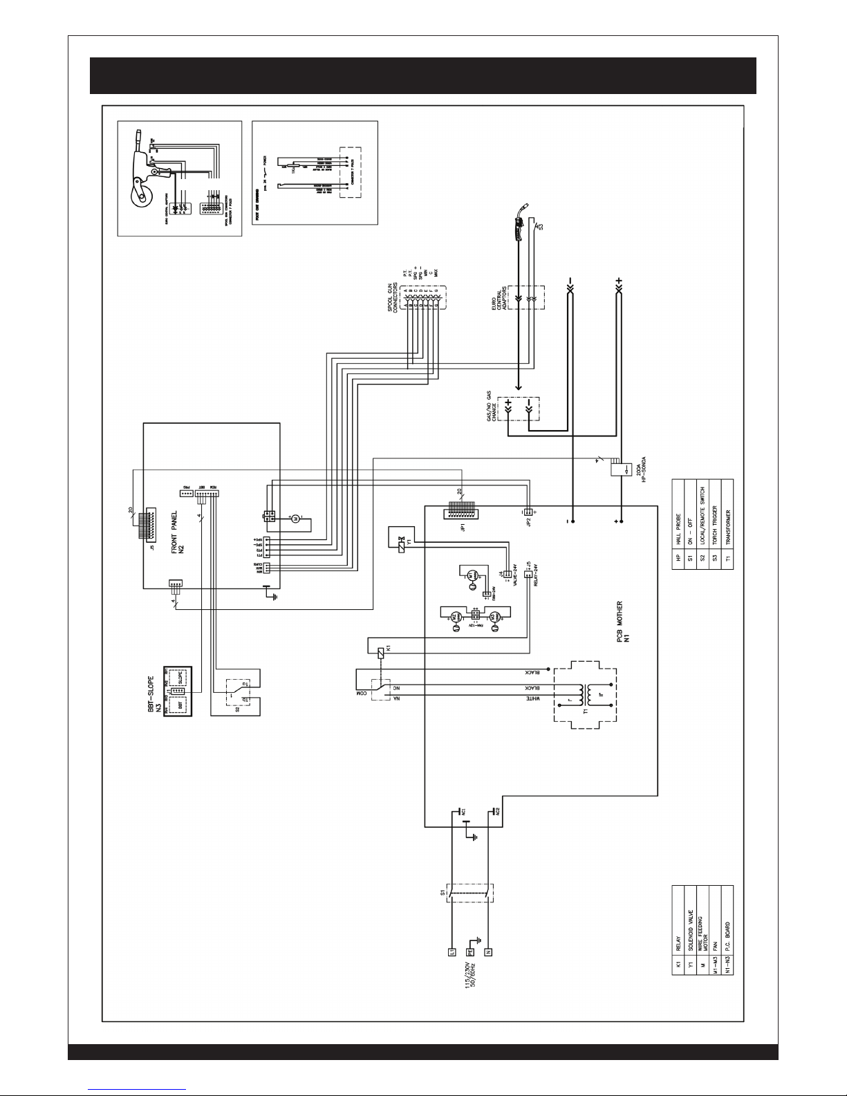
30
WWW.FORNEYIND.COM
Wiring Diagram
BLUE
BLUE
BLUE
WHITE
WHITE
BLACK
BROWN
 Loading...