

Page 1

Contents
BEFORE DRIVING
Introduction 2
Instrumentation 4
Controls and Features 15
Seating and Safety restraints 53
STARTING AND DRIVING
Starting 85
Driving 93
Roadside Emergencies 107
SERVICING
Maintenance and Care 124
Capacities and Specifications 179
Reporting Safety Defects 186
Index 187
1
Page 2

Introduction
ICONS
The following icons appear in this
Owner Guide:
indicates a warning. Read the
following section on Warnings for
a full explanation of warnings.
indicates that vehicle
information related to recycling
and other environmental concerns
will follow.
Warnings
Warnings remind you to be
especially careful in those areas
where carelessness can cause
damage to your vehicle or personal
injury to yourself, your passengers,
or others. Please read all warnings
carefully.
Breaking-in your vehicle
Your new vehicle goes through an
adjustment or breaking-in period
during the first 1,600 km (1,000
miles) of driving. During this
period:
• change your vehicle’s speed
often as you drive. Do not drive
at one speed for a long time.
• use only the type of engine oil
Ford recommends. Do not use
special “break-in” oils.
• avoid sudden stops. The
break-in period for brake linings
lasts for 1,600 km (1,000 miles)
of highway driving or 160 km
(100 miles) of city driving.
2
Page 3

Information about this guide
This guide describes equipment
and gives specifications for
equipment that was in effect when
this guide was approved for
printing. Ford may discontinue
models or change specifications or
design without any notice and
without incurring obligation.
Introduction
3
Page 4
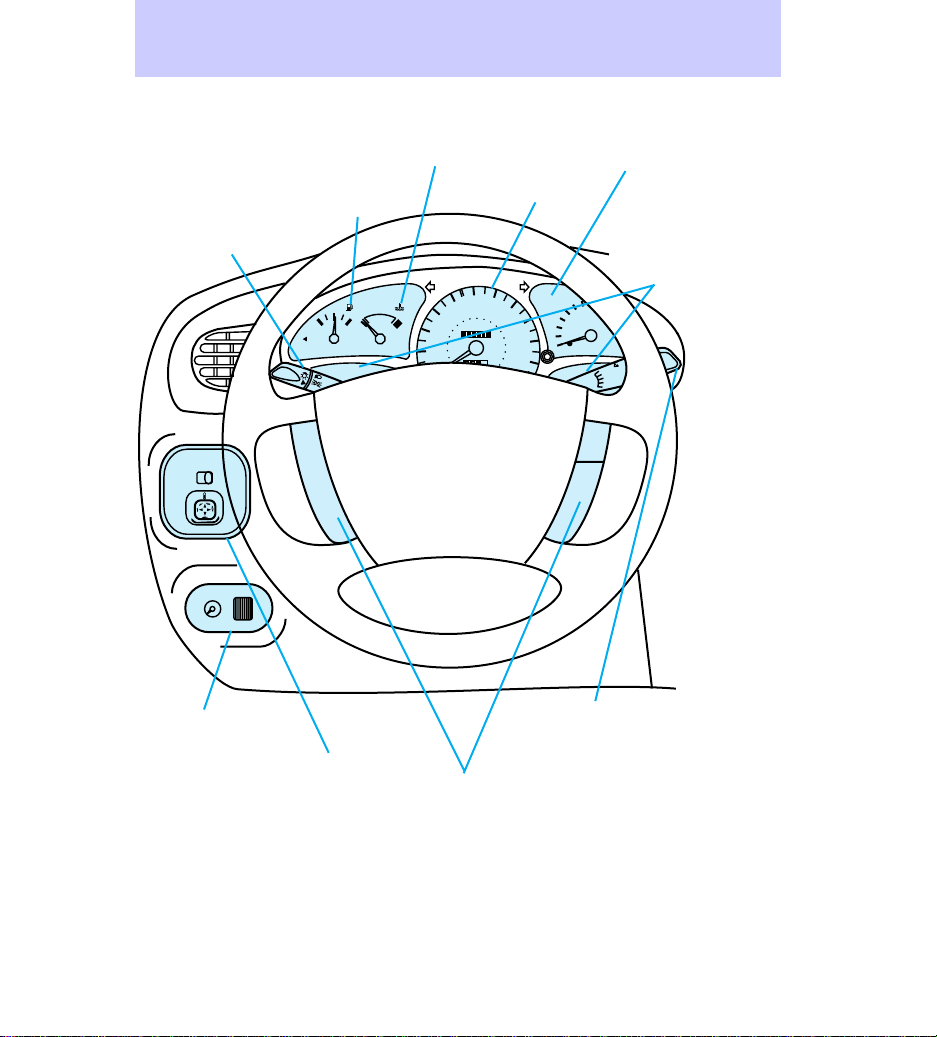
Instrumentation
Exterior lamps and
turn signal lever
(pg. 26 and
pg. 9)
Foglamp switch
(if equipped)
(pg. 27)
MIRRORS
RL
Engine coolant
temperature gauge
(pg. 13)
Fuel gauge
(pg. 13)
1
/
2
E F
FUEL FILL
ON
C H
OFF
OFF
60
50
100
80
40
60
000000
30
40
20
20
0000
Speedometer
(pg. 13)
70
80
120
90
140
100
160
110
180
200
3
2
1
SET
ACC
CST
Tachometer (if
equipped)
(pg. 14)
Warning lights
(pg. 6)
RPM x 1000
MIST
OFF
INT
1
2
RSM
Instrument panel
dimmer switch
(pg. 15)
4
Power mirrors
control (if
equipped)
(pg. 16)
Speed control
(if equipped)
(pg. 27)
Wiper/washer
lever (pg. 30)
Rear wiper/washer
(if equipped) (pg.
30)
Page 5
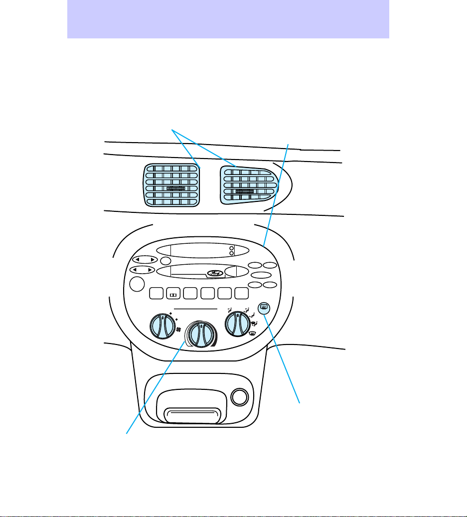
Vents (pg. 18)
Instrumentation
Refer to Audio Guide
(electronic stereo radio with
cassette shown; others
available) (pg. 17)
AM
FM
SEEK
SCAN
TUNE
EJ REW FF
VOL
PUSH ON
1
2
SIDE 1-2
34
LO
HI
Climate controls
(pg. 17)
* if equipped with air conditioning
MAX
A/C
5
A/C
H
TAPE
M
BASS
TREB
–+
BAL
FADE
6
OFF
R.DEF
Rear window
defroster (if
equipped) (pg. 24)
5
Page 6
0
7
1
0
2
Instrumentation
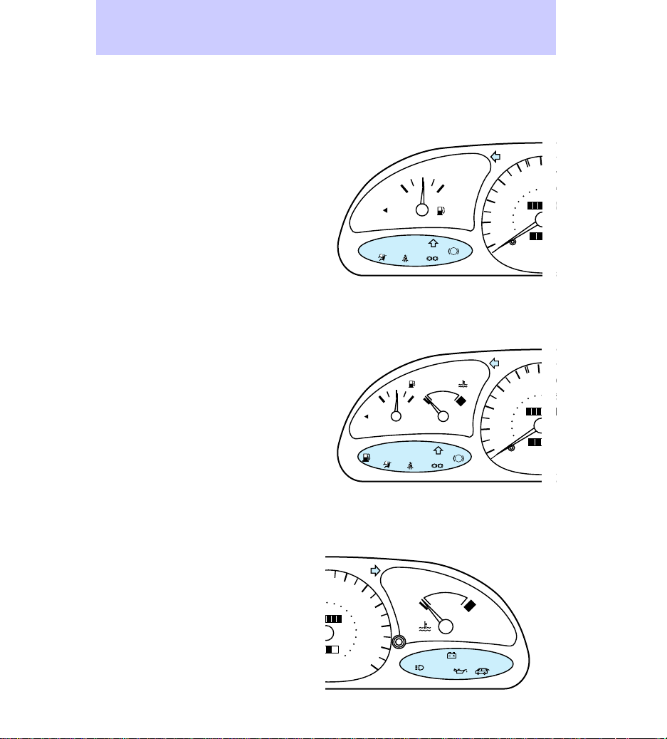
INSTRUMENT CLUSTERS
Instrument cluster lights
Base cluster lights
Sport cluster lights
FUEL FILL
LOW
FUEL
FUEL FILL
SERVICE
ENGINE
SOON
E F
SERVICE
ENGINE
SOON
1
/
2
1
/
2
E F
BRAKE
P!
C H
BRAKE
P
60
50
100
80
40
60
00000
30
40
20
20
0000
10
MPH
ABS
ABS
km/h
60
7
50
100
1
80
40
60
000000
30
40
20
20
0000
10
MPH
km/h
Base cluster lights
1
/
2
E F
FUEL FILL
SERVICE
ENGINE
SOON
LOW
FUEL
6
C H
BRAKE
! P
60
70
50
80
40
60
30
40
20
20
10
MPH
ABS
km/h
100
000000
0000
80
120
90
140
100
160
110
180
200
120
C H
THEFT
CHECK
COOLANT
Page 7
Sport cluster lights
40
60
30
40
20
20
10
FUEL FILL
LOW
FUEL
1
/
E F
SERVICE
ENGINE
SOON
2
C H
ABS
BRAKE
! P
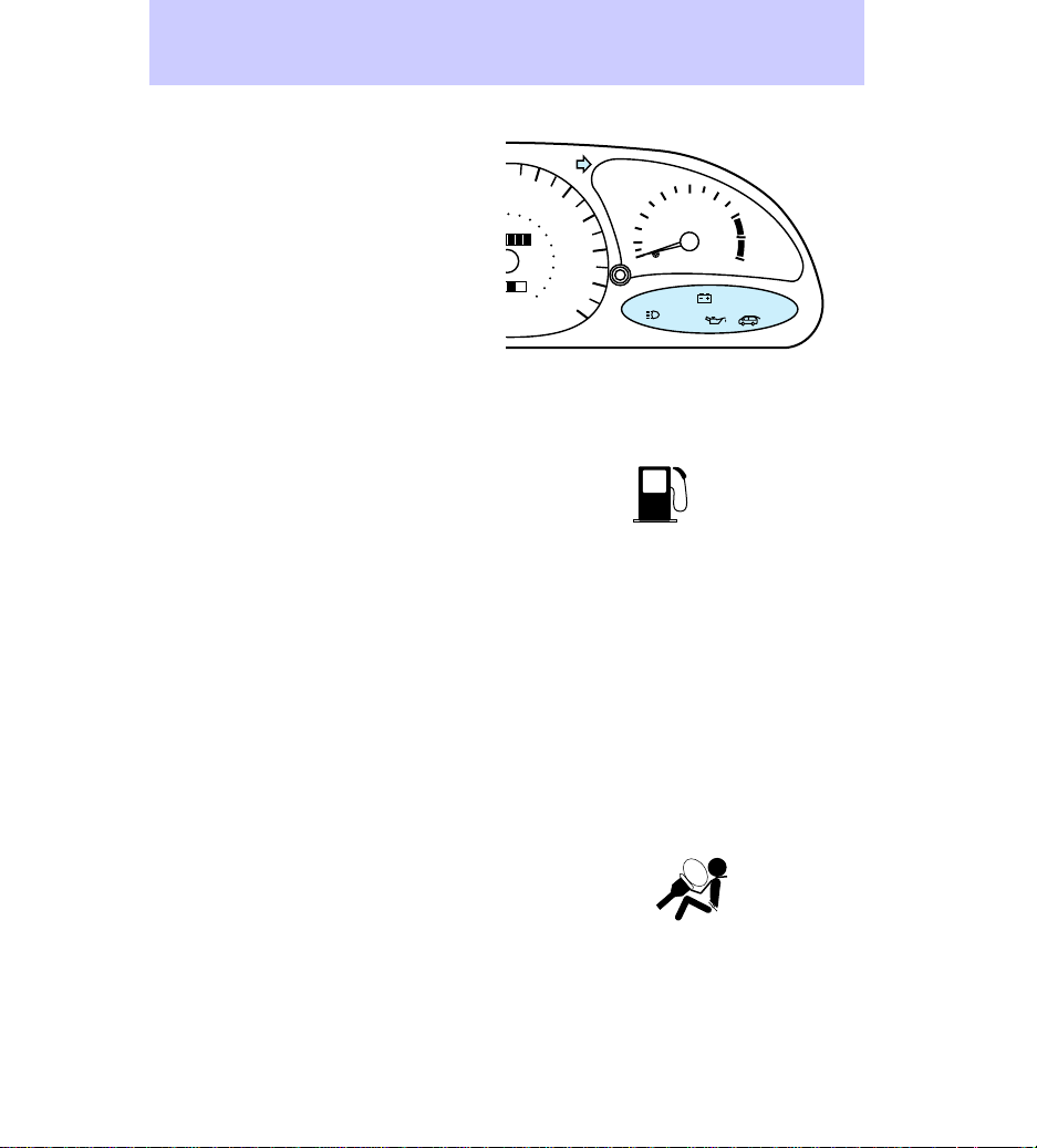
Low fuel
Illuminates when the fuel tank is
almost empty (approximately 8
liters [2 gallons] remain). The
lights will also briefly illuminate
when the ignition key is turned to
ON and the engine is off.
Service engine soon
Illuminates when the engine’s
emissions control system requires
service. The light will also
illuminate, and will remain
illuminated, when the ignition key
is turned to ON and the engine is
off.
Air bag readiness
Illuminates when the air bag
system requires servicing. The
light will also briefly illuminate
when the ignition key is turned to
ON.
MPH
km/h
50
80
60
100
000000
0000
Instrumentation
70
80
120
90
140
100
160
110
180
200
120
4
5
3
2
1
RPM x 1000
THEFT
6
7
8
CHECK
COOLANT
LOW
FUEL
SERVICE
ENGINE
SOON
7
Page 8
Instrumentation
Safety belt
The safety warning light/chime is a
reminder to fasten your safety belt.
One of the following will take
place:
• If the lap/shoulder belt is not
buckled before the key is turned
to the ON position, the
illuminate for approximately one
minute or until the safety belt is
buckled.
• If the lap/shoulder belt is
buckled while
and the chime is sounding, both
will turn off.
• If the lap/shoulder belt is
buckled before the key is turned
to the ON position, neither light
or chime will activate.
Upshift (if equipped)
Illuminates when it is best to shift
to the next highest manual
transaxle gear for the maximum
fuel economy.
Brake
Illuminates when the parking brake
is activated and the ignition is
keyed to ON or the brake fluid
level is low. In addition, with the
parking brake off, the light will
illuminate when the engine is
cranked.
is illuminated
will
BRAKE
!P
8
Page 9
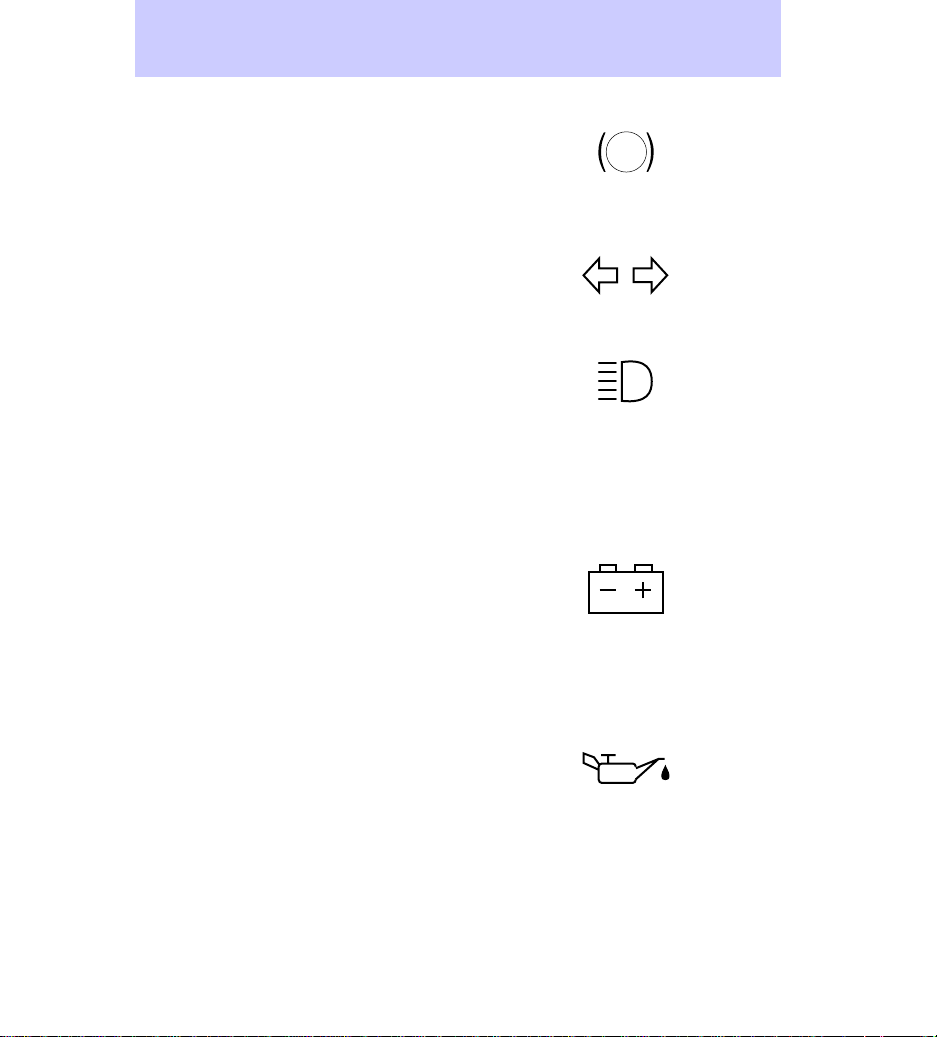
Anti-lock brake system (ABS)
Illuminates when the ABS needs
service. The light will also briefly
illuminate when the ignition key is
turned to ON and the engine is off.
Turn signal
Illuminates when the left hand or
right hand turn signal or the
hazard lamps are illuminated.
High beams
Illuminates when the headlamp
high beams are on.
Anti-theft (if equipped)
Illuminates when the anti-theft
system is arming and flashes when
the anti-theft system is armed.
Charging
Illuminates when there is a
problem with the alternator or
charging system and the electrical
system requires service. The light
will also briefly illuminate when
the ignition key is turned to ON
and the engine is off.
Oil pressure
Illuminates when the oil pressure
is low, not the low oil level.
However, if your engine’s oil level
is low, it could affect the oil
pressure. Stop the vehicle and
check the oil level as soon as
possible. Do not drive the vehicle if
the light remains on. The light will
also briefly illuminate when the
ignition key is turned to ON and
the engine is off.
Instrumentation
ABS
THEFT
9
Page 10
Instrumentation
Engine coolant
Illuminates when there is low
coolant level or a problem with the
engine coolant system. Stop the
vehicle and check the engine
coolant level as soon as possible.
The light will also briefly illuminate
when the ignition key is turned to
ON and the engine is off. For more
information on engine coolant,
refer to Checking and adding
engine coolant in the
Maintenance and care chapter.
Liftgate ajar (if equipped)
Illuminates when the ignition is in
the ON position and the liftgate is
open.
Many of the lights illuminate
briefly when you start the vehicle.
For more information on warning
light illumination, refer to
Preparing to start the vehicle in
the Starting chapter.
CHECK
COOLANT
Warning chimes
Safety belt warning chime
For information on the safety belt
warning chime, refer to the
Seating and safety restraints
chapter.
Supplemental restraint system
(SRS) warning chime
For information on the SRS
warning chime, refer to the
Seating and safety restraints
chapter.
10
Page 11

Key-in-ignition warning chime
A warning chime sounds when the
key is left in the ignition and any
door is opened.
Headlamps-on warning chime
A warning chime sounds when the
headlamps are on, the ignition is
off, and a door is opened.
Instrumentation
11
Page 12
Instrumentation
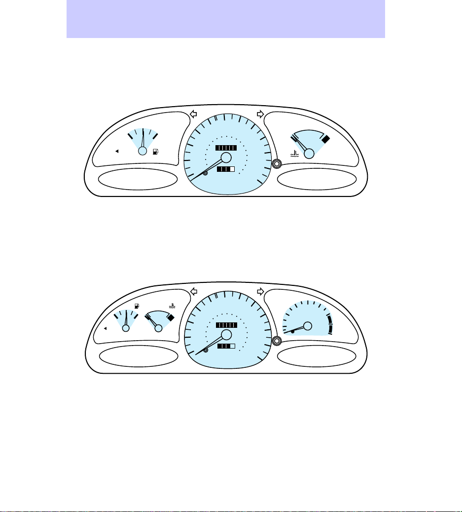
Instrument cluster gauges
Base cluster gauges
1
/
2
E F
FUEL FILL
Sport cluster gauges
1
/
2
FUEL FILL
E F
C H
60
70
50
80
40
60
30
40
20
20
10
MPH
km/h
50
80
40
60
30
40
20
20
10
MPH
km/h
100
000000
0000
60
100
000000
0000
80
120
90
140
100
160
110
180
200
120
70
80
120
90
140
100
160
110
180
200
120
2
1
C H
4
3
RPM x 1000
5
6
7
8
12
Page 13
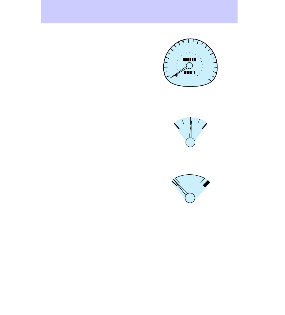
Speedometer
Fuel gauge
When the fuel gauge needle is on
the E (empty) portion of the
gauge, there are between
approximately 2 L (.6 gallons) and
4 L (1 gallon) of usable fuel left in
the tank.
Engine coolant temperature
gauge
If the engine coolant temperature
gauge moves into the H zone:
1. Pull off the road as soon as is
safely possible.
2. Turn off the engine and let it
cool.
3. Check and add engine coolant
as necessary. Refer to Checking
and adding engine coolant in the
Maintenance and care chapter. If
the coolant level and mixture is
not properly maintained, the
engine coolant temperature gauge
will not read properly.
Instrumentation
60
70
40
60
30
40
20
20
10
50
80
MPH
km/h
E F
C H
100
000000
0000
1
/
2
80
120
90
140
100
160
110
180
200
120
13
Page 14
Instrumentation
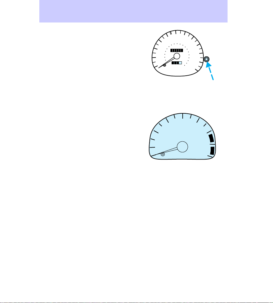
Odometer
The odometer gives a six digit
reading of how many kilometers
(miles) your vehicle has traveled.
Trip odometer
The trip odometer gives a four
digit reading of how many
kilometers (miles) your vehicle has
traveled in an individual trip.
Press the reset button to begin an
individual trip odometer record.
Tachometer
40
30
40
20
10
2
1
50
80
60
000000
20
0000
MPH
km/h
3
RPM x 1000
60
70
80
100
120
90
140
100
160
110
180
200
120
4
5
6
7
8
14
Page 15
60
70
50
3
80
100
120
80
40
1
/
2
E F
C H
FUEL FILL
OFF
ON
MIRROR
L
R
OFF
2
RPM x 1000
90
60
140
000000
30
1
40
100
160
20
20
110
180
MIST
0000
OFF
200
INT
1
RSM
SET
ACC
CST
AM
FM
SEEK
TUNE
SCAN
TUNE
EJ REW FF
DISCS
VOL–
PUSH ON
1
SIDE 1-2
LO
2345
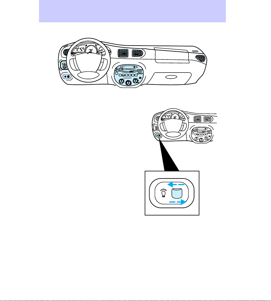
INSTRUMENT PANEL DIMMER
SWITCH
To adjust the instrument panel
dimmer switch:
• Rotate the switch to the right to
dim the instrument panel
lighting.
• Rotate the switch to the left to
brighten the instrument panel
lighting.
Controls and features
TAPE
CD
TREB
BASS
–+
BAL
FADE
COMP1SIDE 1-2
OFF
A/C
*
MAX
*
A/C
HI
60
70
50
3
80
100
120
80
40
1
2
/
2
RPM x 1000
90
E F
C H
60
140
000000
30
1
FUEL FILL
40
100
160
20
20
110
180
000
MIST
OFF
INT
1
O
FF
XXX
MIRROR
L
R
XXXX
2
RESET
SET
ACC
SET
SEEK
TUNE
TUNE
DISCS
VOL–
PUSH ON
1
SIDE 1-2
FM
SCAN
EJ REW FF
2345
LO
HI
TAPECDAM
BASS
TREB
–+
BAL
FADE
COMP1SIDE 1-2
OFF
A/C
*
MAX
*
A/C
15
Page 16
Controls and features
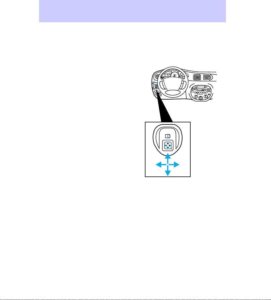
POWER OUTSIDE MIRRORS (IF
EQUIPPED)
To adjust the outside mirrors:
1. Select the mirror you want to
adjust.
L Driver side mirror
R Passenger side mirror
2. Move the mirror control in the
desired direction.
3. Lock the mirror by moving the
switch to the center position.
MIRROR
L
R
1
/
2
E F
C H
FUEL FILL
20
O
FF
XXX
XXXX
MIRRORS
RL
60
70
50
3
80
100
120
80
40
2
RPM x 1000
90
60
140
000000
30
1
40
100
160
20
110
180
000
MIST
OFF
INT
1
2
RESET
SET
ACC
SET
SEEK
TUNE
TUNE
DISCS
VOL–
PUSH ON
1
SIDE 1-2
FM
SCAN
EJ REW FF
2345
LO
HI
TAPECDAM
BASS
TREB
–+
BAL
FADE
COMP1SIDE 1-2
OFF
A/C
*
MAX
*
A/C
16
Page 17
AUDIO SYSTEM
For information on the audio
system, refer to the Audio Guide.
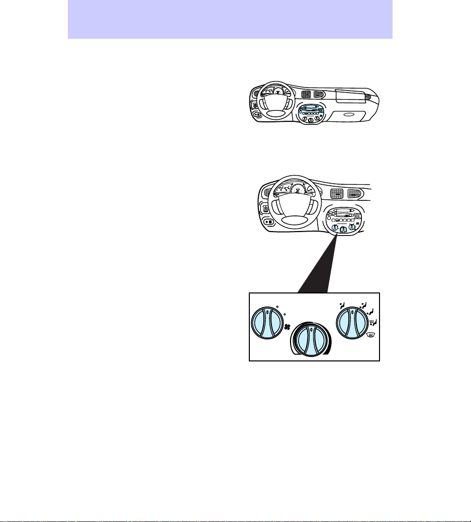
CLIMATE CONTROLS
Your vehicle has one of the
following climate control systems:
• Manual heating system
• Manual heating and air
conditioning system
In some modes, the two systems
function similarly; in modes where
the systems do not function
similarly, the different functions
are noted.
Controls and features
60
70
50
3
80
100
120
80
40
1
2
/
2
RPM x 1000
90
E F
C H
60
140
000000
30
1
FUEL FILL
40
100
160
20
20
110
180
000
O
F
F
RESET
XXX
MIRROR
L
R
SET
ACC
XXXX
SET
1
/
2
E F
C H
FUEL FILL
OFF
XXX
MIRROR
L
R
XXXX
TAPECDAM
FM
SEEK
TUNE
SCAN
BASS
TREB
TUNE
EJ REW FF
DISCS
–+
VOL–
PUSH ON
BAL
FADE
1
2345
SIDE 1-2
COMP1SIDE 1-2
OFF
LO
A/C
*
MAX
*
A/C
HI
60
70
50
3
80
100
120
80
40
2
RPM x 1000
90
60
140
000000
30
1
40
100
160
20
20
110
180
000
MIST
OFF
INT
1
2
RESET
SET
ACC
SET
SEEK
TUNE
TUNE
DISCS
VOL–
PUSH ON
1
SIDE 1-2
FM
SCAN
EJ REW FF
2345
LO
HI
TAPECDAM
BASS
TREB
–+
BAL
FADE
COMP1SIDE 1-2
OFF
A/C
*
MAX
*
A/C
* If equipped with air conditioning
LO
HI
OFF
A/C
*
MAX
*
A/C
17
Page 18
HI
LO
OFF
*
A/C
*
MAX
A/C
TUNE
DISCS
SEEK
TUNE
SCAN
EJ REW FF
BAL
BASS
TREB
FADE
TAPECDAM
FM
–+
1
SIDE 1-2
2345
COMP1SIDE 1-2
VOL–
PUSH ON
SET
ACC
SET
Controls and features
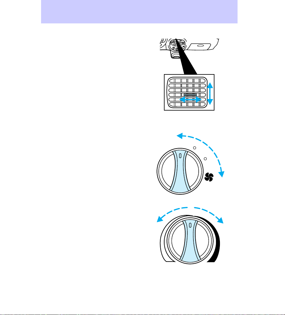
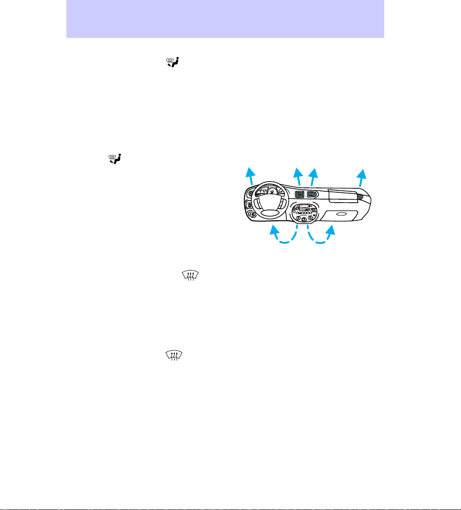
Vents
The airflow from the vents may be
adjusted by moving the horizontal
lever or by moving the vent up and
down according to your airflow
preference.
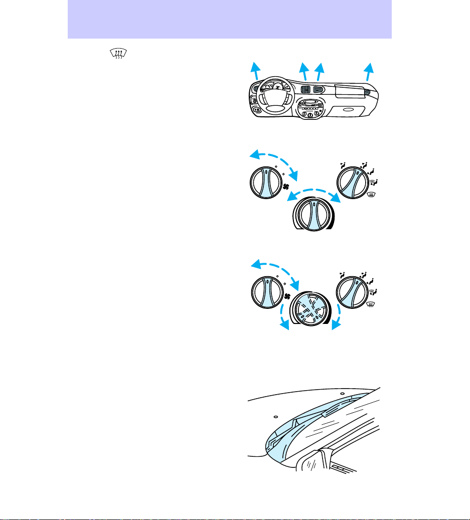
Operating the climate control
Turn the fan speed dial to the
desired speed.
LO
HI
Turn the temperature dial to the
desired mix of warm and cool air
(left for cooler and right for
warmer).
18
Page 19

Turn the air distribution dial to the
desired airflow position. For
vehicles with manual heating
systems, the modes can only be
used for heating or ventilating
(except OFF).
To prevent humidity buildup inside
of the vehicle, always drive with
the climate control system turned
on.
Do not put objects under the front
seats that interfere with the flow
of air to the back seat area.
* If equipped with air conditioning
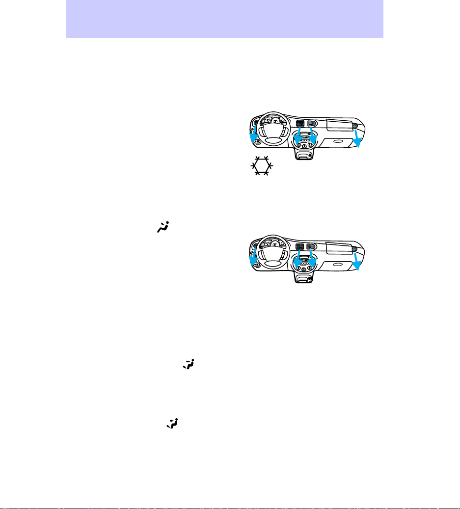
Using the MAX A/C mode
• MAX A/C mode (if equipped)
can be used for air conditioning
or heating. This mode is noisier
but more economical than A/C;
it will only function if the air
temperature outside the vehicle
is about 10°C (50°F) or higher.
Select MAX A/C and turn the
temperature dial to the left for
recirculated, cooled airflow
through these vents:
Controls and features
OFF
A/C
*
MAX
*
A/C
60
70
50
3
80
100
120
80
40
1
2
/
2
RPM x 1000
90
E F
C H
60
140
000000
30
1
FUEL FILL
40
100
160
20
20
110
180
000
O
F
F
RESET
XXX
MIRROR
L
R
SET
ACC
XXXX
TAPECDAM
FM
SEEK
SET
TUNE
SCAN
BASS
TREB
TUNE
EJ REW FF
DISCS
–+
VOL–
PUSH ON
BAL
FADE
1
2345
SIDE 1-2
COMP1SIDE 1-2
OFF
LO
A/C
*
MAX
*
A/C
HI
Using the A/C mode
• A/C mode (if equipped) can be
used for heating, ventilating, or
air conditioning; the air
19
Page 20
Controls and features
conditioning can only function if
the air temperature outside the
vehicle is about 10°C (50°F) or
higher. Select A/C and turn the
temperature dial to the left for
recirculated, cooled airflow
through these vents:
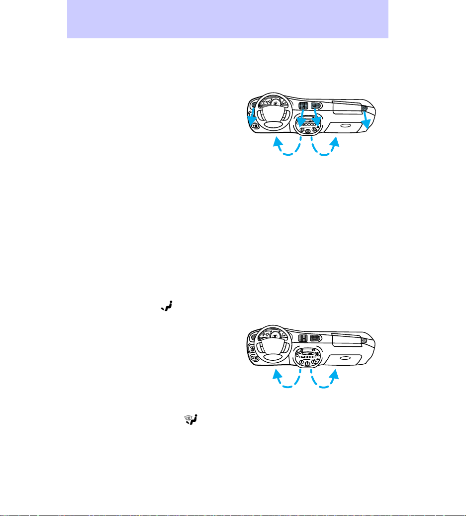
Using the panel mode
• This brings in outside air and
can be used for heating and
ventilating. Select
through these vents:
Using the floor mode
In the OFF mode, outside air is
shut out and the fan will not
operate.
Using the panel/floor mode
Manual heating system
• This mode brings in outside air
and can be used for heating and
ventilating.
Manual heating and air
conditioning system
• This mode brings in outside air
and can be used for heating,
ventilating, or air conditioning;
the air conditioning can only
for airflow
60
70
50
3
80
100
120
80
40
1
2
/
2
RPM x 1000
90
E F
C H
60
140
000000
30
1
FUEL FILL
40
100
160
20
20
110
180
000
O
F
F
RESET
XXX
MIRROR
L
R
SET
ACC
XXXX
60
70
50
80
100
120
80
40
1
/
2
90
E F
C H
60
140
000000
30
FUEL FILL
40
100
160
20
20
110
180
000
O
F
F
XXX
MIRROR
L
R
XXXX
TAPECDAM
FM
SEEK
SET
TUNE
SCAN
BASS
TREB
TUNE
EJ REW FF
DISCS
–+
VOL–
PUSH ON
BAL
FADE
1
2345
SIDE 1-2
COMP1SIDE 1-2
OFF
LO
A/C
*
MAX
*
A/C
HI
3
2
RPM x 1000
1
RESET
SET
ACC
TAPECDAM
FM
SEEK
SET
TUNE
SCAN
BASS
TREB
TUNE
EJ REW FF
DISCS
–+
VOL–
PUSH ON
BAL
FADE
1
2345
SIDE 1-2
COMP1SIDE 1-2
OFF
LO
A/C
*
MAX
*
A/C
HI
20
Page 21
function if the air temperature
outside the vehicle is about
10°C (50°F) or higher. Select
this mode for airflow through
these vents:
Using the floor mode
In this mode, with the temperature
control knob between full cool and
full hot ranges, slightly warmer air
will be directed toward your feet
and cooler air toward your chest.
In the full cool or full hot ranges,
the airflow toward both feet and
chest will be the same
temperature.
• This allows for maximum
heating, but can also be used for
ventilating. Select
for
airflow through the rear seat
floor ducts and these vents:
Controls and features
60
70
50
3
80
100
120
80
40
1
2
/
2
RPM x 1000
90
E F
C H
60
140
000000
30
1
FUEL FILL
40
100
160
20
20
110
180
000
O
F
F
RESET
XXX
MIRROR
L
R
MIRROR
L
R
SET
ACC
XXXX
SET
60
70
50
3
80
100
120
80
40
1
2
/
2
90
E F
C H
60
140
000000
30
1
FUEL FILL
40
100
160
20
20
110
180
000
O
F
F
XXX
SET
ACC
XXXX
SET
TAPECDAM
FM
SEEK
TUNE
SCAN
BASS
TREB
TUNE
EJ REW FF
DISCS
–+
VOL–
PUSH ON
BAL
FADE
1
2345
SIDE 1-2
COMP1SIDE 1-2
OFF
LO
A/C
*
MAX
*
A/C
HI
RPM x 1000
RESET
TAPECDAM
FM
SEEK
TUNE
SCAN
BASS
TREB
TUNE
EJ REW FF
DISCS
–+
VOL–
PUSH ON
BAL
FADE
1
2345
SIDE 1-2
COMP1SIDE 1-2
OFF
LO
A/C
*
MAX
*
A/C
HI
Using the defrost/floor mode
Manual heating system
• This brings in outside air and
can be used for heating or
ventilating.
21
Page 22
Controls and features
Manual heating and air
conditioning system
• This brings in outside air and
can be used for heating,
ventilating, or air conditioning in
order to dehumidify the
windshield; the air conditioning
can only function if the air
temperature outside the vehicle
is about 10°C (50°F) or higher.
Select
these vents:
Using the defrost mode
Manual heating system
• This brings in outside air and
can be used for heating and
ventilating and will clear ice or
fog from the windshield and
front side windows.
Manual heating and air
conditioning system
• This brings in outside air and
can be used for heating,
ventilating, or air conditioning in
order to dehumidify the
windshield; the air conditioning
can only function if the air
temperature outside the vehicle
is about 10°C (50°F) or higher.
for airflow through
60
70
50
3
80
100
120
80
40
1
2
/
2
RPM x 1000
90
E F
C H
60
140
000000
30
1
FUEL FILL
40
100
160
20
20
110
180
000
O
F
F
RESET
XXX
MIRROR
L
R
SET
ACC
XXXX
SET
TUNE
DISCS
SEEK
TUNE
VOL–
PUSH ON
SIDE 1-2
FM
SCAN
EJ REW FF
1
LO
2345
HI
TAPECDAM
BASS
TREB
–+
BAL
FADE
COMP1SIDE 1-2
OFF
A/C
*
MAX
*
A/C
22
Page 23
Select for airflow through
these vents:
Special features
For slightly warm airflow toward
your feet and slightly cool airflow
toward your chest at the same
time:
* If equipped with air conditioning
For about the same temperature
airflow toward your chest and feet:
Controls and features
60
70
50
3
80
100
120
80
40
1
2
/
2
RPM x 1000
90
E F
C H
60
140
000000
30
1
FUEL FILL
40
100
160
20
20
110
180
000
O
F
F
RESET
XXX
MIRROR
L
R
SET
ACC
XXXX
SET
LO
HI
LO
TAPECDAM
FM
SEEK
TUNE
SCAN
BASS
TREB
TUNE
EJ REW FF
DISCS
–+
VOL–
PUSH ON
BAL
FADE
1
2345
SIDE 1-2
COMP1SIDE 1-2
OFF
LO
A/C
*
MAX
*
A/C
HI
OFF
A/C
*
MAX
*
A/C
OFF
A/C
*
HI
MAX
*
A/C
* If equipped with air conditioning
For better airflow
Remove snow, ice, and leaves from
the intake vents for the best
airflow:
23
Page 24
Controls and features
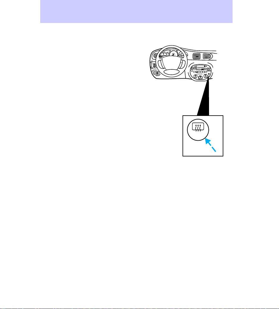
REAR WINDOW DEFROSTER
(IF EQUIPPED)
Press the defroster switch to clear
the rear window of thin ice and
fog:
The ignition must be in the ON
position to operate the rear
window defroster.
The defroster turns off
automatically after fifteen minutes.
To manually turn off the defroster
before fifteen minutes have passed,
push the switch again.
60
70
50
3
80
100
120
80
40
1
2
/
2
RPM x 1000
90
E F
C H
60
140
000000
30
1
FUEL FILL
40
100
160
20
20
110
180
000
MIST
OFF
INT
1
O
FF
XXX
MIRROR
L
R
XXXX
2
RESET
SET
ACC
SET
SEEK
TUNE
SCAN
TUNE
DISCS
VOL–
PUSH ON
1
SIDE 1-2
LO
FM
EJ REW FF
2345
HI
TAPECDAM
BASS
TREB
–+
BAL
FADE
COMP1SIDE 1-2
OFF
A/C
*
MAX
*
A/C
R.DEF
24
Page 25
60
70
50
3
80
100
120
80
40
MIRRORS
1
/
2
E F
C H
30
FUEL FILL
20
OFF
ON
RL
OFF
2
90
60
140
000000
1
40
100
160
20
110
180
0000
200
SET
ACC
CST
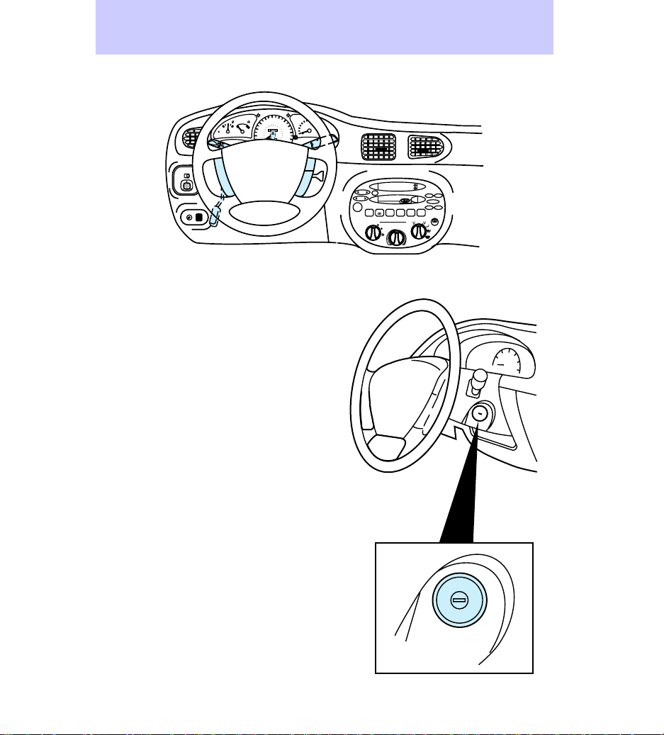
Ignition
LOCK locks the steering wheel and
allows the key to be removed from
the ignition. (Push the key in while
turning to LOCK on vehicles with
manual transaxles.) LOCK also
locks automatic transaxle
gearshifts.
Controls and features
RPM x 1000
MIST
OFF
INT
1
2
RSM
AM
FM
SEEK
SCAN
TUNE
EJ REW FF
VOL
PUSH ON
1
SIDE 1-2
LO
TAPE
BASS
TREB
–+
BAL
2
34
HI
FADE
5
6
OFF
A/C
MAX
A/C
ACC
I
0
LOCK
ON
START
II
III
25
Page 26
Controls and features
ACC allows operation of some
accessories without starting the
engine.
ON allows testing of the vehicle’s
warning lights.
START cranks the engine. The key
returns to the ON position after it
is released.
For more information on the
vehicle ignition and starting the
vehicle, refer to Preparing to start
the vehicle in the Starting
chapter.
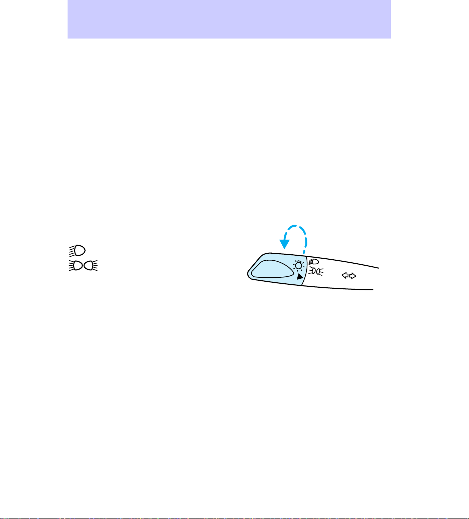
Headlamp switch
Rotate the headlamp switch to the
desired position.
Headlamps on
Parking lamps, side marker
lamps, instrument panel lamps,
license lamps, and tail lamps on
OFF Lamps off
OFF
Daytime running light (DRL)
system (if equipped)
The DRL system turns on the high
beam headlamps, with a reduced
light output, when:
• the vehicle is running
• the vehicle has a fully released
parking brake
• the headlamp system is in the
OFF position
26
Page 27
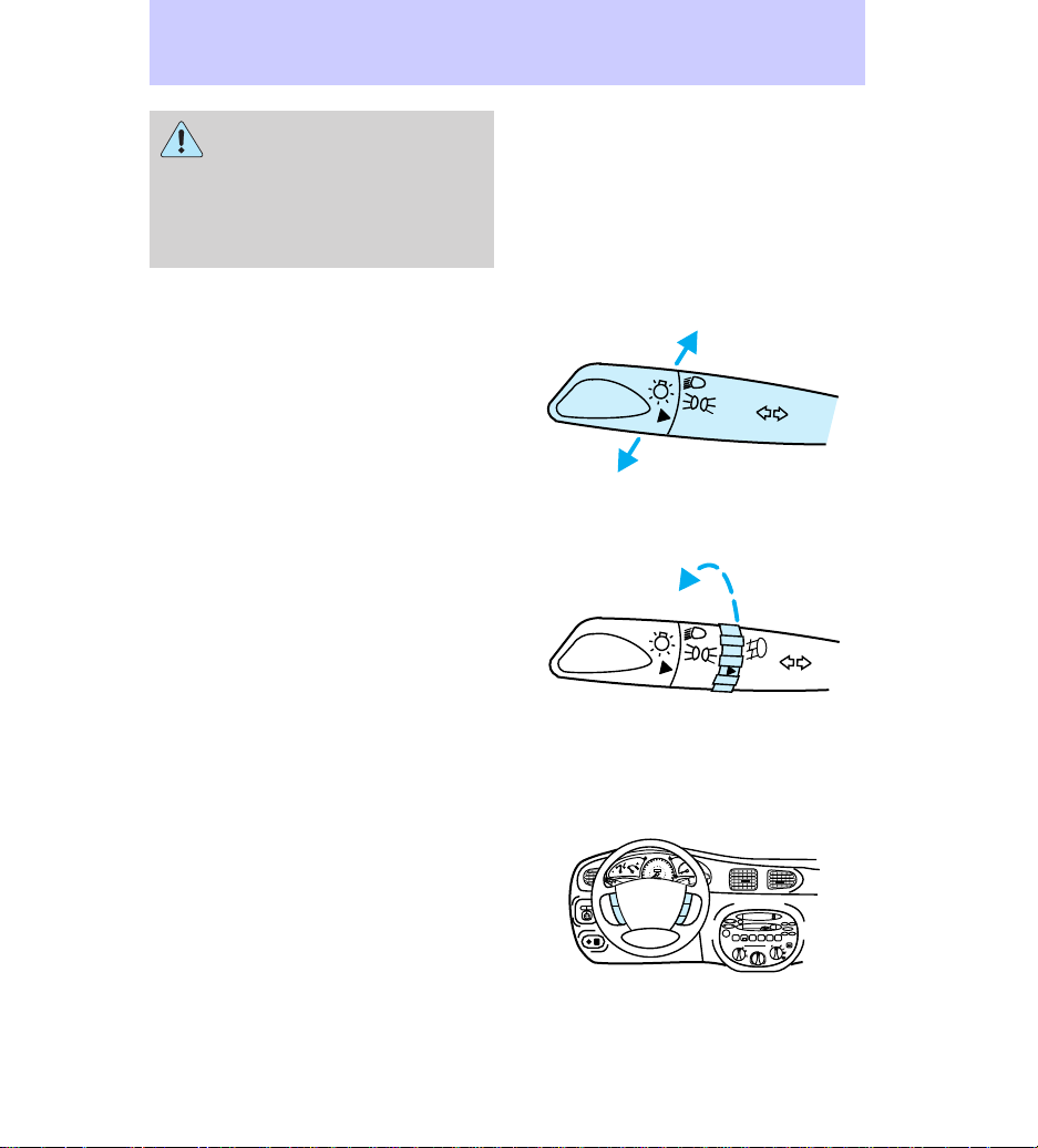
The daytime running light
(DRL) system will not
illuminate the tail lamps and
parking lamps. Turn on your
headlamps at dusk. Failure to do
so may result in a collision.
High beams and flash-to-pass
Push for high beam headlamp
operation.
Pull and release quickly for
“flash-to-pass” operation.
Foglamps (if equipped)
Rotate the switch to turn the
foglamps on and off.
Controls and features
OFF
OFF
OFF
Speed control (if equipped)
Maintain vehicle speed at least 50
km/h (30 mph) to operate the
speed control system.
60
70
50
3
80
100
120
80
40
1
2
/
2
RPM x 1000
90
E F
C H
60
140
000000
30
1
FUEL FILL
40
100
160
20
20
110
180
000
MIST
OFF
INT
1
OFF
XXX
MIRROR
L
R
XXXX
2
RESET
SET
ACC
SET
SEEK
TUNE
TUNE
DISCS
VOL–
PUSH ON
SIDE 1-2
FM
SCAN
EJ REW FF
1
2345
LO
HI
TAPECDAM
BASS
TREB
–+
BAL
FADE
COMP1SIDE 1-2
OFF
A/C
*
MAX
*
A/C
27
Page 28
Controls and features
Press the ON portion of the ON /
OFF button to turn on.
Press the OFF portion of the ON /
OFF button to turn off.
Press the RSM button to resume a
set speed.
Hold the SET ACC portion of the
SET ACC / CST button to set the
desired speed. Hold SET ACC to
increase speed; tap to increase
speed in 1.6 km/h (1 mph)
increments.
Hold the CST portion of the SET
ACC / CST button to decrease
speed; tap to decrease speed; tap
to decrease speed in 1.6 km/h (1
mph) increments.
Speed control can be canceled by
pressing the brake pedal or clutch
pedal (if equipped).
Do not shift into N (automatic
transaxle) or neutral (manual
transaxle) with the speed control
on.
Use only Federal Communications
Commission (FCC) or Canadian
Radio and Telecommunications
Commission (CRTC) approved
radio transmitting equipment in
your vehicle to prevent speed
control malfunctions.
20
0
ON
OFF
40
20
20
160
180
SRS
100
110
RSM
SET
ACC
CST
28
Page 29
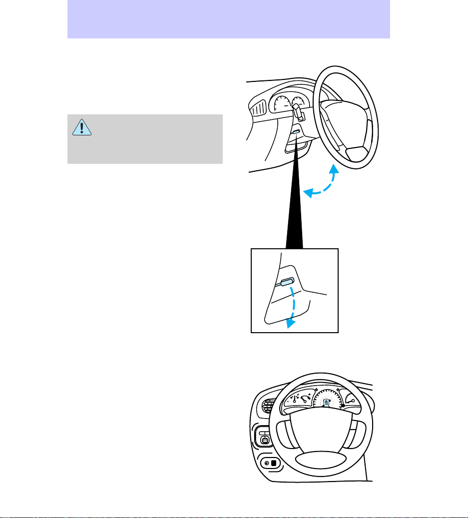
Tilt steering (if equipped)
Pull the lever down to adjust the
steering column angle.
Push the lever back up to lock the
steering wheel in position.
Never adjust the steering
wheel when the vehicle is
moving. You could lose control of
the vehicle and injure someone.
Controls and features
Hazard flasher switch
For information on the hazard
flasher switch, refer to the
Roadside emergencies chapter.
1
/
2
E F
C H
30
FUEL FILL
20
ON
MIRROR
R
L
OFF
2
RPM x 1000
90
60
140
000000
1
40
100
160
20
110
180
0000
200
RSM
SET
ACC
CST
60
70
50
3
80
100
120
80
40
29
Page 30
Controls and features
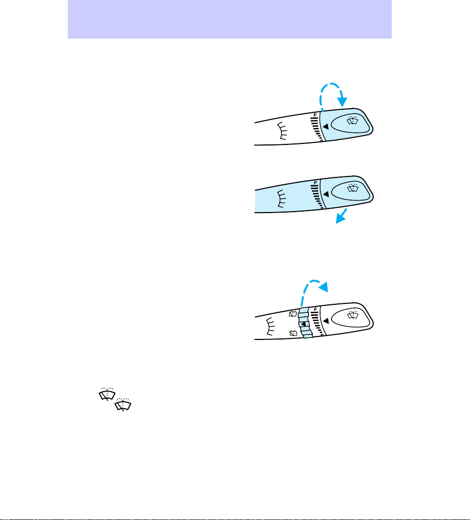
Windshield wipers and washer
Wipers
Rotate the windshield wiper switch
to the desired interval position.
Push up and release to wipe the
windshield only once. Pull down to
select the wipers on continuously.
Washer
Pull toward you for windshield
washer fluid operation.
Rear window wipers and
washer (if equipped)
Wipers
For rear operation, rotate the rear
window wiper and washer switch
to the desired position. Select:
ON Rear wiper on
OFF Rear wiper and washer off
MIST
OFF
2
MIST
OFF
INT
1
2
MIST
OFF
INT
1
2
ON
INT
OFF
1
INT
PULL
INT
PULL
INT
PULL
Washer
For rear window washer fluid
operation, pull toward you. Select:
Top Rear washer on
Bottom
Brief rear wiper
and washer operation (for quick
cleaning).
30
Page 31

OVERHEAD CONTROLS
Overhead Lamps
Move the overhead lamp switch to
the desired position:
OFF Overhead lamp off
DOOR Overhead lamp illuminates
when a door is opened
ON Overhead lamp on
Map lamps (if equipped)
Press to turn the map lamps on
and off.
DOOR MOUNTED CONTROLS
Power door locks (if equipped)
Push to lock or unlock the doors.
L All doors locked
U All doors unlocked
Controls and features
OFF DOOR ON
LU
LOCK
31
Page 32

Controls and features
• Driver side
• Front passenger side
LOCK
L
LU
U
32
Page 33

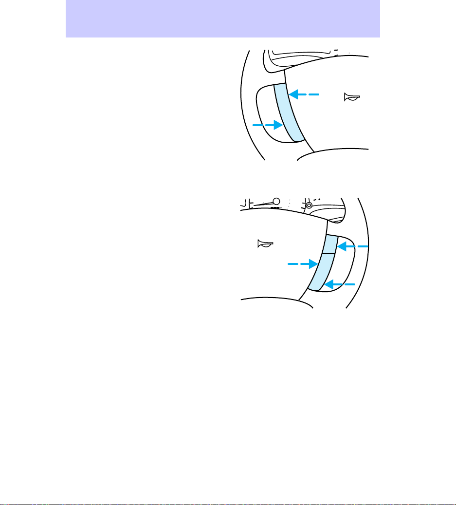
Childproof locks
The rear doors can be set to
prevent children from opening the
doors from the inside. To set the
rear childproof locks:
The childproof lock must be set
separately for each door. Setting
the lock on one door will not set
the lock for both rear doors.
To return the rear doors to normal
operation, return the lever to the
raised position.
Controls and features
Illuminated entry (if equipped)
For more information on the
illuminated entry system, refer to
Illuminated entry under Remote
entry system in this chapter.
33
Page 34

Controls and features
Power windows (if equipped)
Driver side controls
Press the appropriate window
switch to operate the power
windows.
• Driver window
• Front passenger window
LU
LOCK
LOCK
• Left rear passenger window
34
LOCK
LOCK
Page 35

• Right rear passenger window
Controls and features
LOCK
To prevent passengers from
operating the power windows,
press the lock button.
Press again to unlock and allow
the passengers to operate the
power windows.
One-touch down feature
To open the driver side window
completely, press and release the
lower portion of the driver side
window switch.
To stop the window while it is in
motion, press the switch again.
Passenger controls
Press the window switch to
operate the power window at each
door position.
LU
LOCK
35
Page 36

Controls and features
• Front passenger side
• Rear passengers
CONSOLE CONTROLS
U
L
Gearshift
For information about the gearshift
on vehicles with automatic or
manual transaxles, refer to the
Transaxles section of the Driving
chapter.
36
Page 37

• Automatic
• Manual
Controls and features
531
42
R
37
Page 38

Controls and features
Parking brake
For information on the parking
brake, refer to Preparing to start
the vehicle in the Driving
chapter.
38
Page 39

FLOOR CONTROLS
Floor mat hook (if equipped)
Fasten the floor mat to the floor to
prevent the mat from shifting.
Controls and features
39
Page 40

Controls and features
TRUNK/LIFTGATE CONTROLS
Compact disc changer (if
equipped)
For information on compact disc
changer, refer to the Audio Guide.
Wagon liftgate lamp
Press the switch to turn the
liftgate lamp on or off.
OFF
ON
40
Page 41

Wagon sliding shade
Pull the shade to cover the cargo
area.
Hook the shade into the notches in
the rear trim panels.
Controls and features
Rewinding the sliding shade
If the shade is damaged or loses its
spring tension from excessive use,
manual rewind of the shade may
be necessary. The following
procedure is a two-person
operation:
41
Page 42

Controls and features
1. Remove the shade from the
mounting brackets by detaching
the safety clip and pressure fit
plastic knobs from either side of
the shade. Extend the shade fully
with the smooth grain facing you.
2. Wrap the vinyl around the tube
twice by twisting the tube away
from you. Tuck the edges of the
vinyl inside the end cap with each
wrap.
3. Fold the vinyl toward the center,
making sure the edges clear the
end cap slots. Use tape or a rubber
band to hold the vinyl on the left
side of the tube.
4. Push in the right end cap
(marked R) about 6 mm (1/4 inch)
to disengage the clutch and hold in
while turning the tube toward you
fourteen times.
5. Let go of the right end cap and
unfold the vinyl. Place the vinyl
into the end cap slots.
6. Place the shade back in the
vehicle.
To avoid possible injury
during a sudden stop or
collision, the cover should be
attached to the brackets when
not in use.
42
Page 43

Fuel pump shut-off switch
The fuel pump shut-off switch
stops the fuel pump when the
vehicle has been involved in a
collision or substantial jolt. If the
vehicle does not start, it is possible
that the fuel pump shut-off switch
needs to be reset.
If you see or smell fuel, do
not reset the switch or try
to start your vehicle. Have all the
passengers get out of the vehicle
and call the local fire department
or a towing service.
The fuel pump shut-off switch is
located in the rear passenger side
of your vehicle. With the sedan
model, a label marks its location.
Press the button on the switch to
reset the fuel pump:
• Sedan
Controls and features
43
Page 44

Controls and features
• Wagon
44
Page 45

REMOTE ENTRY AND
ANTI-THEFT SYSTEM
• Sedan
• Wagon
Controls and features
LOCK
UN
LOCK
PANIC
TRUNK
LOCK
LOCK
UN
PANIC
Remote entry system (if
equipped)
The remote entry system is
available as a driver-door only or
as an all-door system. The remote
entry features only operate with
the ignition in the OFF position.
When the ignition is in ON or ACC,
the system is disarmed. If the
vehicle is left running and locked,
the system will not allow reentry
using the remote entry transmitter.
The operating range of the remote
entry system may be affected by
weather conditions (such as very
45
Page 46

Controls and features
cold temperatures) or structures
around the vehicle (buildings,
other vehicles, radio and TV
towers, etc.). Typical operating
range will allow you to be up to 10
meters (33 ft) away from your
vehicle.
Unlocking the doors and wagon
liftgate
Driver-door only system
• Press once to unlock the driver
side door.
• Press again within five seconds
to unlock the wagon liftgate (if
equipped)
• Sedan
PANIC
LOCK
TRUNK
LOCK
UN
• Wagon
All-door system
• Press once to unlock the driver
side door.
46
LOCK
PANIC
LOCK
UN
Page 47

• Press again within five seconds
to unlock passenger doors and
wagon liftgate (if equipped).
Opening the trunk (if equipped)
Press once to open the trunk.
• Sedan
Locking the doors
Driver-door only system
• Press once to lock only the
driver’s door.
• Press again within five seconds
to verify system has attempted
to lock the door (horn will
sound once and parking lamps
will flash).
The remote opens and locks the
driver’s door only, it will not
activate the other three doors.
A bright yellow key fob and
‘‘DRIVER’S DOOR ONLY’’ label are
provided with your remote entry
system. They provide an additional
reminder that the remote entry
system locks and unlocks only the
driver’s door.
If the other doors are unlocked,
they will remain unlocked even
after the system has locked the
Controls and features
LOCK
UN
PANIC
LOCK
TRUNK
47
Page 48

Controls and features
driver’s door. The other doors must
be locked manually.
• Sedan
PANIC
LOCK
TRUNK
LOCK
UN
• Wagon
All-door system
• Press once to lock all doors.
• Press again within five seconds
to verify doors are locked (horn
will sound once and parking
lamps will flash).
If a door is ajar, the horn will
sound twice when the LOCK
button is pressed a second time
with the all-door system.
LOCK
PANIC
LOCK
UN
48
Page 49

Sounding a panic alarm
Press once to sound an alarm
(with either the driver-door only or
all-door system).
• Sedan
Controls and features
LOCK
UN
LOCK
PANIC
TRUNK
• Wagon
The parking lamps flash, the horn
sounds, and the illuminated entry
system turns on.
Press a second time to turn off the
alarm.
Illuminated entry
Interior lamps illuminate when the
UNLOCK button is pressed on the
remote entry transmitter (if
equipped). The illuminated entry
function illuminates the interior
overhead lamp for approximately
20 seconds, until the key is
inserted into the ignition and
turned to ON, or until the LOCK
button is pressed on the remote
entry transmitter. The interior
overhead lamp must be set to the
DOOR position in order for the
LOCK
PANIC
LOCK
UN
49
Page 50

Controls and features
illuminated entry system to
activate.
Anti-theft system (if equipped)
The anti-theft system protects
against unauthorized entry into an
armed and locked vehicle. When
an unauthorized entry occurs, the
system activates and:
• flashes the parking lamps and
anti-theft indicator light
• sounds the horn
The horn and parking lamps shut
off after approximately three
minutes. The lights and horn will
remain off unless another
unauthorized entry is attempted.
Arming the system
The anti-theft system can be
armed when:
• the ignition is in the LOCK
position and the key is removed
• the panic alarm is off
• all doors are closed
50
Page 51

Press once to arm the anti-theft
system.
The THEFT light in the instrument
cluster illuminates until the arming
procedure is complete. After the
arming procedure is complete, the
THEFT light flashes.
Disarming an untriggered
system
Press once to disarm the
untriggered anti-theft system.
If the driver armed the system but
did not exit the vehicle, the system
can also be disarmed by inserting
the key and turning the ignition to
ON.
The system will not disarm by
using the key in any door/trunk
lock cylinder.
Controls and features
LOCK
UN
LOCK
PANIC
TRUNK
LOCK
UN
LOCK
PANIC
LOCK
UN
LOCK
PANIC
TRUNK
LOCK
UN
LOCK
PANIC
51
Page 52

Controls and features
Disarming a triggered system
Press either the UNLOCK or
PANIC button to disarm a
triggered anti-theft system.
A triggered system can also be
disarmed by inserting the key and
turning the ignition to ON.
This device complies with Part 15
of the FCC rules. Operation is
subject to the two following
conditions: (1) this device may not
cause harmful interference, and
(2) this device must accept any
interference received, including
interference that may cause
undesired operation.
Replacement batteries for the
remote entry and/or anti-theft
system transmitters can be
purchased at pharmacies, watch
stores, or at authorized dealers.
If a transmitter is lost, a new one
may be programmed by your
dealer. Take any remaining
transmitters with you to the dealer
so they may be reprogrammed.
The system will work with up to
four transmitters. Your vehicle
comes equipped with two
transmitters; additional
transmitters can be ordered from
your dealer. It will be necessary to
have all of the transmitters
programmed to the remote entry
system by the dealer at the same
time.
PANIC
LOCK
LOCK
PANIC
TRUNK
LOCK
UN
UN
LOCK
52
Page 53

FRONT SEATS
Lift handle to slide the seat
forward or backward
Lift to adjust the seatback
Seating and safety restraints
53
Page 54

Seating and safety restraints
Head restraints
Push the release button to lower
the head restraint
To raise the head restraint, pull
without pushing the release
button.
REAR SEATS
Stow the built-in child seat (if
equipped) in order to fold the rear
seatback down. Refer to Built-in
child seat in this chapter for more
information.
Push the seatback back to a raised
position and latch for normal
seating.
The full rear seat bench is shown.
The split-folding rear seat (if
equipped) operates in a similar
manner.
Press to unlock the seatback:
54
Page 55

Seating and safety restraints
SAFETY RESTRAINTS
PRECAUTIONS
The use of safety belts helps to
restrain you and your passengers
in case of a collision. In most
states and in Canada, the law
requires the use of safety belts.
To reduce the risk of
serious injury in a
collision, always drive and ride
with your seatback upright and
the lap belt snug and low across
the hips.
Safety belts must be worn
by all vehicle occupants to
be properly restrained and help
reduce the risk of injury in a
collision.
To prevent the risk of
injury make sure children
sit where they can be properly
restrained.
It is extremely dangerous
to ride in a cargo area,
inside or outside of a vehicle. In
a collision, people riding in these
areas are more likely to be
seriously injured or killed.
Do not allow people to
ride in any area of your
vehicle that is not equipped with
seats and safety belts.
55
Page 56

Seating and safety restraints
Be sure everyone in your
vehicle is in a seat and
using a safety belt properly.
USING THE SAFETY
RESTRAINTS PROPERLY
Combination lap and shoulder
belts
Insert the tongue into the slot to
fasten.
Push the red release button and
remove the tongue from the slot to
unfasten.
The lap belts should fit
snugly and as low as
possible around the hips, not
around the waist.
The outboard safety restraints in
the vehicle are combination lap
and shoulder safety belts. The
front and rear seat passenger
outboard safety belts have the two
types of locking modes.
56
Page 57

Seating and safety restraints
Vehicle sensitive (emergency)
locking mode
The vehicle sensitive mode is the
normal retractor mode, which
locks the belts in response to
vehicle movement. For example, if
the driver brakes suddenly or turns
a corner sharply, the combination
safety belts will lock to restrain
forward movement of the driver
and passengers.
The retractor can be made to lock
by pulling sharply on the belt.
Automatic locking mode
In this mode, the occupant is
locked in a certain position by the
shoulder belt and the belt does not
adjust tightness during vehicle
movement.
The automatic locking mode is not
available on the driver safety belt.
When to use the automatic
locking mode
• When a tight lap and shoulder
belt fit is desired.
• Any time a child safety seat is
installed in the vehicle. For
more information on the proper
use of a child safety seat, refer
to Children and infant or
child safety seats later in this
chapter.
57
Page 58

Seating and safety restraints
Using the automatic locking
mode
The automatic locking mode must
be used when installing an
aftermarket child safety seat in any
outboard passenger seat.
1. Buckle the combination lap and
shoulder belt.
2. Grasp the shoulder belt portion
and pull downward until the entire
belt is extracted.
3. Allow the belt to retract. As the
belt retracts, you will hear a
clicking sound. This indicates that
the safety belt is now in the
automatic locking mode.
Canceling the automatic locking
mode
Disconnect the combination lap
and shoulder belt and allow it to
completely retract. This will cancel
the automatic locking mode and
activate the vehicle sensitive
(emergency locking) mode.
58
Page 59

Seating and safety restraints
Front seat safety belt height
adjustment
Adjust the height of the shoulder
belt so the belt rests across the
middle of your shoulder.
• To lower the height of the
shoulder belt:
Push the button down.
Slide down.
• To raise the height of the
shoulder belt:
Slide up.
Pull down on the height
adjustment assembly to make sure
it is locked in place.
Lap belt
A lap belt is located in the center
of the rear seat.
Adjusting the lap belt
Because the lap belt does not have
a retractor to automatically adjust
itself during vehicle movement, the
lap belt should be adjusted before
use.
• To shorten the belt:
59
Page 60

Seating and safety restraints
Buckle the belt. Pull the loose end
of the belt until snug.
• To lengthen the belt:
Tip and pull the tongue.
The lap belt must fit snugly and as
low as possible around the hips.
Do not wear the lap belt around
your waist.
Safety belt maintenance
Check the safety belt systems
periodically for damage and to
ensure that they work properly.
60
Page 61

Seating and safety restraints
The short plastic boot on the front
safety belt at the passenger
inboard buckle location covers an
energy absorbing sew pattern on
the safety belt. In the event of a
collision, the sew pattern may
release, and the orange portion of
the warning label may become
visible. If this occurs, the safety
belt and buckle must be replaced.
Failure to follow these
instructions will affect the
performance of the safety belts
and increase the risk of personal
injury.
61
Page 62

Seating and safety restraints
SAFETY BELT INDICATOR
LIGHT AND WARNING CHIME
illuminates in the instrument
cluster and a chime sounds to
remind the occupants to fasten
their safety belts.
Conditions of operation
If... Then...
The driver’s safety belt is not
buckled before the ignition key is
turned to ON...
The driver’s side safety belt is
buckled while the indicator light is
illuminated and the warning
chime is sounding...
The driver’s safety belt is buckled
before the ignition key is turned
to ON...
AIR BAG PRECAUTIONS
Your vehicle is equipped with an
air bag supplemental restraint
system (SRS) designed to work
with the safety belts to help
protect you and your right front
seat passenger in the event of a
collision.
The safety belt indicator
illuminates for one to two minutes
and the warning chime sounds for
4-8 seconds.
The safety belt indicator light and
the warning chime turn off.
The safety belt indicator light and
warning chime remain off.
All occupants of the
vehicle, including the
driver, should always wear their
safety belts, even when an air
bag SRS is provided.
62
Page 63

Seating and safety restraints
Do not place objects or
mount equipment on or
near the air bag cover on the
steering wheel or in front seat
areas that may come into contact
with a deploying air bag. Failure
to follow this instruction may
increase the risk of personal
injury in the event of a collision.
Do not attempt to service,
repair, or modify the air
bag SRS or its fuses. See your
Ford or Lincoln-Mercury dealer.
AIR BAG SYSTEM
DESCRIPTION
The air bags and their
corresponding warning and
information labels are found in the
following locations:
The air bag system activates in
collisions more severe than hitting
a parked vehicle (of similar size
and weight) head-on at
approximately 20 km/h (13 mph).
This activation speed may vary if
your vehicle is involved in a
collision with something that will
move or deform and according to
the angle of impact. The air bag is
not designed to inflate in rollovers,
side impacts, or rear impacts.
Air bags and air bag equipped
vehicles should be disposed of only
by qualified service personnel
using Ford approved procedures.
The system consists of two parts:
60
70
50
3
80
100
120
80
40
1
2
/
2
RPM x 1000
90
E F
C H
60
140
000000
30
1
FUEL FILL
100
40
160
20
20
T
IS
110
180
M
F
0000
F
O
T
200
IN
1
OFF
RSM
ON
MIRROR
L
R
SET
ACC
OFF
CST
TUNE
DISCS
SEEK
TUNE
VOL–
PUSH ON
SIDE 1-2
FM
SCAN
EJ REW FF
1
LO
2345
HI
TAPECDAM
BASS
TREB
–+
BAL
FADE
COMP1SIDE 1-2
OFF
A/C
*
MAX
*
A/C
63
Page 64

Seating and safety restraints
• The driver air bag in the middle
of the steering wheel and the
passenger air bag above the
glove compartment.
• The electrical system, made up
of impact sensors, a diagnostic
module, and a backup power
supply.
The air bags inflate within a
fraction of a second after air bag
sensors detect a severe frontal
collision. Gas generators within the
air bags fill the air bags with a
non-toxic, non-flammable gas.
After the vehicle occupants have
impacted the air bags, the gas
empties through holes in the air
bags and the air bags deflate. You
may notice smoke and smell the
escaping gas after the air bags
deflate. This is normal.
You and your passenger must wear
your safety belts in order for the
air bag system to operate
effectively.
AIR BAG WARNING LIGHT AND
WARNING CHIME
When you turn the ignition key to
the ON position, the air bag system
performs a self-check of the:
• air bag sensors
• air bag module
• air bag inflators
• available battery power
• air bag warning light
Following a successful system
self-check, the
64
warning light
Page 65

Seating and safety restraints
in the instrument cluster
illuminates for approximately six
seconds to indicate that the
system is functional.
If you hear a group of five beeps,
or if the
not illuminate, stays lit, or flashes,
the air bag system requires
immediate service. Have the
vehicle serviced by your dealer.
CHILD RESTRAINT
PRECAUTIONS
You are required by law to use
safety restraints for children in the
United States and Canada. If small
children ride in your vehicle
(generally children who are four
years of age or younger and who
weigh 18 kg [40 lb] or less), you
must put them in safety seats
made specially for children. Check
your local and state laws for
specific requirements regarding the
safety of your children.
warning light does
Never let a passenger hold
a child on his or her lap
while the vehicle is moving. The
passenger cannot protect the
child from injury in a collision.
Always follow the instructions and
warnings that come with any infant
or child restraint you might use.
If possible, place children in the
rear seat of your vehicle. Accident
statistics suggest that children are
safer when properly restrained in
rear seating positions than when
65
Page 66

Seating and safety restraints
they are restrained in front seating
positions.
Rear-facing infant seats
should never be placed in
the front seat.
CHILDREN AND SAFETY BELTS
Children who are too large for
child safety seats (as specified by
the manufacturer of your child
safety seat) should always wear
safety belts.
Follow all the important safety
restraint and air bag precautions
that apply to adult passengers in
your vehicle.
If the shoulder belt portion of a
combination lap and shoulder belt
can be positioned so it does not
cross or rest in front of the child’s
face or neck, the child should wear
the lap and shoulder belt. Moving
the child closer to the center of
the vehicle may help to provide a
good shoulder belt fit.
To improve the fit of lap and
shoulder belts on children who
have outgrown child safety seats,
Ford recommends use of a
belt-positioning booster seat that is
labelled as conforming to all
Federal motor vehicle safety
standards. Belt-positioning booster
seats raise the child and provide a
shorter, firmer seating cushion that
encourages safer seating posture
and better fit of lap and shoulder
belts on the child. A
66
Page 67

Seating and safety restraints
belt-positioning booster should be
used if the shoulder belt rests in
front of the child’s face or neck, or
if the lap belt does not fit snugly
on both thighs, or if the thighs are
too short to let the child sit all the
way back on the seat cushion
when the lower legs hang over the
edge of the seat cushion. You may
wish to dicuss the specific needs of
your child with your pediatrician.
CHILDREN AND INFANT OR
CHILD SAFETY SEATS
Carefully follow all of the
manufacturer’s instructions
included with the safety seat you
put in your vehicle. If you do not
install and use the safety seat
properly, the child may be
injured in a sudden stop or
collision.
When installing a child safety seat:
• use the correct safety belt
buckle for that seating position.
• make sure the tongue is
securely fastened in the buckle.
• keep the buckle release button
pointing up and away from the
safety seat, with the tongue
between the child seat and the
release button, to prevent
accidental unbuckling.
• place seatbacks in the upright
position.
67
Page 68

Seating and safety restraints
• put the safety belt in the
automatic locking mode. Refer
to Using the automatic locking
mode in this chapter.
Installing child safety seats in
combination lap and shoulder
belt seating positions
1. Position the child safety seat in
a seat with a combination lap and
shoulder belt.
If you choose to install a child
safety seat in the front passenger
seat, move the seat as far back as
possible.
2. Pull down on the shoulder belt
and then grasp the shoulder belt
and lap belt together.
68
Page 69

Seating and safety restraints
3. While holding the shoulder and
lap belt portions together, route
the tongue through the child seat
according to the child seat
manufacturer’s instructions. Be
sure the belt webbing is not
twisted.
4. Insert the belt tongue into the
proper buckle until you hear and
feel the latch engage. Make sure
the tongue is latched securely by
pulling on it.
5. To put the retractor in the
automatic locking mode, grasp the
shoulder portion of the belt and
pull downward until all of the belt
is extracted.
6. Allow the belt to retract. The
belt will click as it retracts to
indicate it is in the automatic
locking mode.
69
Page 70

Seating and safety restraints
7. Pull the lap belt portion across
the child seat toward the buckle
and pull up on the shoulder belt
while pushing down on the child
seat to tighten the belt as much as
possible.
8. Allow the safety belt to retract
to remove any slack in the belt.
9. Before placing the child in the
seat, forcibly tilt the seat from side
to side and forward and back to
make sure the seat is securely held
in place.
10. Try to pull the belt out of the
retractor to make sure the
retractor is in the automatic
locking mode (you should not be
able to pull more belt out). If the
retractor is not locked, unbuckle
the belt and repeat steps two
through nine.
• Check to make sure the child
seat is properly secured before
each use.
Installing child safety seats in
the rear center seating position
1. Tip the tongue and pull to
lengthen the lap belt.
2. Place the child safety seat in the
center seating position.
3. Route the lap belt through the
child safety seat according to the
child seat manufacturer’s
instructions.
70
Page 71

Seating and safety restraints
4. Insert the tongue into the
proper buckle.
5. Push down on the child safety
seat while pulling on the loose part
of the lap belt webbing to tighten
the belt.
6. Before placing the child in the
child safety seat, forcibly tilt the
seat from side to side and forward
and back to make sure the seat is
securely held in place. If the child
seat moves excessively, repeat
steps five and six or properly
install the child seat in a different
seating position.
Using a tether strap
Contact the manufacturer of your
safety seat for information about
ordering a tether strap if one is not
provided with the seat. The tether
anchor hardware kit is part
number 613D20.
Your vehicle has tether anchor
attachment locations on the rear
package tray behind the back seat
(sedan) or along the rear edge of
the roof (wagon). Carefully follow
the instructions provided with the
kit.
71
Page 72

Seating and safety restraints
Tether anchor hardware
(Canadian vehicles only)
All vehicles built for sale in Canada
include a tether anchor hardware
kit for use with Canadian child
safety seats. Attachment holes (at
each rear seating position) have
been provided in your vehicle to
attach the anchor hardware, if
required. Additional kits can be
obtained at no charge from any
Ford or Lincoln-Mercury dealer.
Tether anchor hardware (US
vehicles only)
Vehicles built for sale in the US do
not include a tether anchor
hardware kit for use with child
safety seats. However, attachment
holes (at each rear seating
position) have been provided in
your vehicle to attach the anchor
hardware, if required. Kits can be
obtained at no charge from any
Ford or Lincoln-Mercury dealer.
Only use the tether
attachment hole locations
shown. The tether anchor may
not perform properly if the
wrong mounting location is used.
Ford recommends using child
safety seats with a top tether strap
designed to secure an aftermarket
child safety seat in the front or
rear seating position. Follow the
child safety seat manufacturer’s
instructions for installing a child
safety seat with a tether strap.
72
Page 73

Seating and safety restraints
Ford recommends you attach
tethered safety seats in a rear
seating position with the tether
strap attached to the tether
anchoring bracket as shown in the
instructions provided with the
tether anchor kit.
If a tethered seat must be installed
in the front passenger seat:
1. Install the child safety seat in
the front passenger seat. For
instructions on how to install the
seat, refer to Installing child
safety seats in combination lap
and shoulder belt seating
positions in this chapter.
2. Hook the tether strap clip to the
tongue of the rear center lap belt
and ensure that the belt is pulled
tight.
To install a child safety seat using
a tether strap in the back seat:
1. Install the child safety seat in
the rear right, left or center seat
position. For instructions on how
to install the seat, refer to
Installing child safety seats in
lap belt seating positions in this
chapter.
• Sedan
73
Page 74

Seating and safety restraints
• Wagon
2. Refer to the instructions
provided with the tether anchor
kit.
3. Refer to the instructions
provided with your child safety
seat to securely attach the child
safety seat by tether to the tether
strap anchor location.
Failure to follow these
precautions could increase
the risk and / or severity of
injury in a collision.
BUILT-IN CHILD SEAT (IF
EQUIPPED)
The rear seat may include a
built-in child seat. This child seat
conforms to all federal and
Canadian motor vehicle safety
standards.
Read the labels located on the
child seat cushion and the
shoulder belt for information on
the built-in child seat.
Use the built-in child seat only
under the following conditions:
At least one year old 10-27 kg (22-60 lb) Shoulders must be
below the shoulder
harness slots on the
built-in child seat
Children not meeting these
requirements should be secured in
an approved aftermarket child
seat. Refer to Children and
infant or child safety seats in this
chapter.
74
Page 75

Seating and safety restraints
Regularly inspect the lap and
shoulder belt system of your child
seat. If there is any damage to the
system or if it is not functioning
properly, see your dealer.
Placing your child in the built-in
child seat
Failure to follow all of the
instructions on the use of
this child restraint system can
result in your child striking the
vehicle’s interior during a sudden
stop or crash.
Never use the built-in
child seat as a booster
cushion with the adult safety
belts. A child using the adult
belts could slide forward and out
from under the safety belts.
The rear seatback must be
fully locked before
operating the child restraint
system.
75
Page 76

Seating and safety restraints
Ensure that the latch release
buttons are in the full up (locked)
position.
When the latch release buttons are
in full up (locked) position and the
built-in child seat is open, the rear
seatback cannot be unlocked or
folded down.
1. Pull down the top portion of the
child seat.
76
Page 77

Seating and safety restraints
2. Release the cushion retention
clip.
3. Lower the child seat cushion.
If the child seat cannot be opened,
return it to the dealer for repair.
77
Page 78

Seating and safety restraints
4. Fold the end portion of the child
seat under the child seat cushion.
5. Disconnect the chest clip, if
connected. Squeeze together the
release tabs on the top and bottom
of the chest clip.
78
Page 79

Seating and safety restraints
6. Place the child in the seat and
position the shoulder belts.
7. Insert the left safety belt tongue
into the left side of the buckle.
Repeat for the right side. Verify
that the indicator window on each
tongue is green to ensure proper
safety belt connections.
79
Page 80

Seating and safety restraints
If both tongues do not
latch in the buckle, do not
use the child seat. See your
dealer for repairs.
8. Fasten the left and right chest
clip halves together to hold the
shoulder belts in place comfortably
on the child’s shoulders. Verify
that the indicator window on the
chest clip is green to ensure a
proper chest clip connection.
• When either of the tongues or
the chest clip is unbuckled, the
red color appears in the window.
• The chest clip is designed to
pull apart easily in the event of
collision. The clip helps keep
the belts on the shoulders of a
squirming or sleeping child.
9. Pull on the safety belt tongues
to ensure they are both securely
latched. If they are not latched,
repeat steps seven and eight.
If necessary, the shoulder belts can
be put in the automatic lock mode
to limit the child’s movement in
the child seat. The mode may be
used if the child is sleeping or
attempting to get out of the child
seat.
If not placed in an automatic
locking mode, the child seat
shoulder belts are in the vehicle
sensitive (emergency locking)
mode which locks the shoulder
belt in the event of a crash, hard
braking, or hard cornering.
80
Page 81

Seating and safety restraints
Activating the automatic locking
mode on the built-in child seat
1. Fully pull out both shoulder
belts.
2. Allow the belts to tighten snugly
against the child’s shoulders.
Canceling the automatic locking
mode on the built-in child seat
1. Disconnect the chest clip. Press
the buckle release button and
remove both safety belt tongues
from the buckle.
2. Slide both shoulder belts from
the child’s shoulders and arm and
allow them to retract fully.
81
Page 82

Seating and safety restraints
Removing your child from the
built-in child seat
1. Disconnect the chest clip by
squeezing the release tabs together
and pulling the two sides apart.
82
Page 83

Seating and safety restraints
2. Press the release button on the
buckle.
3. Slide the shoulder belts off the
child’s shoulders and remove the
child.
4. Return the child seat cushion to
the stowed (upright) position.
5. Ensure the shoulder belts are in
the center of the built-in child
seatback and connect the cushion
retention clip.
6. Fold the child seat into the
seatback and tuck the top of the
child seat under the rear seat flap.
7. Press firmly on the center of the
built-in child seat to ensure it is
stowed properly.
When not in use, the built-in child
seat can be stowed so that the rear
center seat position may be used
or the rear seatback can be folded
down.
83
Page 84

Seating and safety restraints
Inspecting the built-in child seat
after a collision
All built-in child restraints,
including seats, buckles,
retractors, seat latches,
interlocks, and attaching
hardware should be inspected by
a qualified Dealer technician
after any collision. If the child
seat was in use during a
collision, Ford recommends
replacing it. However, if the
collision was minor and a
qualified technician finds that
the child restraints do not show
damage and continue to operate
properly, they do not need to be
replaced. Built-in child seats not
in use during a collision should
also be inspected and replaced if
either damage or improper
operation is noted.
For information on cleaning your
built-in child seat, refer to
Cleaning the built-in child seat
in the Maintenance and care
section.
84
Page 85

A computer system controls the
engine’s idle revolutions per
minute (RPM). When the engine
starts, the idle RPM runs higher
than when the engine is warm. If
the engine idle speed does not
slow down automatically, have the
vehicle checked. Do not allow the
vehicle to idle for more than ten
minutes.
Extended idling at high
engine speeds can produce
very high temperatures in the
engine and exhaust system,
creating the risk of fire or other
damage.
Do not park, idle, or drive
your vehicle in dry grass
or other dry ground cover. The
emission system heats up the
engine compartment and exhaust
system, which can start a fire.
Starting
Do not start your vehicle
in a closed garage or other
enclosed area. Never sit in a
stopped vehicle for more than a
short period of time with the
engine running. Exhaust fumes
are toxic. For more information
and instructions, refer to
Guarding against exhaust
fumes in this chapter.
85
Page 86

Starting
PREPARING TO START THE
VEHICLE
Engine starting is controlled by the
spark ignition system. This system
meets all Canadian
Interference-Causing Equipment
standard requirements regulating
the impulse electrical field strength
of radio noise.
Before starting the vehicle:
1. Make sure all vehicle occupants
have buckled their safety belts. For
more information on safety belts
and their proper usage, refer to
the Seating and safety restraints
chapter.
2. Make sure the headlamps and
vehicle accessories are off.
If starting a vehicle with an
automatic transaxle:
• Make sure the parking brake
is set.
OFF
86
Page 87

If starting a vehicle with an
automatic transaxle:
• make sure that the gearshift is
in P.
If starting a vehicle with a manual
transaxle:
• push the clutch pedal to the
floor.
• place the gearshift in the
neutral position.
Starting
P
R
N
D
D
L
531
42
R
87
Page 88

Starting
4. Turn the key to the ON position
(without turning the key to
START). Make sure the following
lights illuminate briefly. If a light
fails to illuminate, have the vehicle
serviced.
If the driver’s safety belt is
fastened, the
illuminate.
light does not
ON
START
II
III
I
ACC
0
LOCK
5
80
40
60
30
40
20
20
CHECK
COOLANT
10
MP
km/
SERVICE
ENGINE
SOON
LOW
FUEL
0
80
120
90
140
100
160
110
180
200
120
ABS
THEFT
STARTING THE VEHICLE
After completing the steps under
Preparing to start the vehicle:
1. Turn the key to START and
release. Do not press the
accelerator.
• The key will return to the ON
position.
2. After idling for a few seconds,
apply the brake and release the
parking brake.
88
ACC
LOCK
ON
START
II
III
I
0
Page 89

Special conditions when
starting
Starting a cold engine
At temperatures -12°C (10°F) and
below, do not hold the key in the
START position longer than 15
seconds. If the engine does not
start on the first attempt:
1. Turn the ignition key to LOCK
and wait approximately ten
seconds.
2. Try starting the engine again.
At temperatures above -12°C
(10°F), do not hold the key in the
START position longer than five
seconds. If the engine does not
start on the first attempt:
1. Turn the ignition key to LOCK
and wait approximately five
seconds.
2. Try starting the engine again.
Starting a warm engine
Do not hold the key in the START
position longer than five seconds.
If the engine does not start on the
first attempt:
1. Turn the ignition key to LOCK
and wait a few seconds until the
starter stops.
2. Try starting the engine again.
Starting the engine after two
failed attempts
If the engine does not start after
two attempts:
1. Turn the key to LOCK and wait
about two minutes.
Starting
89
Page 90

Starting
2. Press the accelerator all the way
to the floor and hold.
3. Turn the key to START. Release
it once the engine starts.
4. Release the accelerator
gradually as the engine speeds up.
If the engine still does not start,
refer to Fuel pump shut-off
switch in the Roadside
emergencies chapter.
Using the engine block heater
(if equipped)
Engine block heaters are strongly
recommended if you live in a
region where temperatures
consistently reach -29°C (-20°F) or
below during the winter months.
An engine block heater warms the
engine coolant, which improves
starting, warms up the engine
faster, and allows the
heater-defrost system to respond
quickly.
If your vehicle is equipped with an
engine block heater, use it
whenever the temperature is -23°C
(-10°F) or below.
To turn the heater on, plug it into
a grounded 110-volt outlet. It is
recommended that you use a
110-volt circuit that is protected
by a Ground Fault Circuit
Interrupter.
For best results, plug the heater in
at least three hours before you
start your vehicle. Using the heater
for longer than three hours will not
damage the engine, so you can
90
Page 91

plug it in at night to start the
vehicle the next morning.
Do not use your heater
with ungrounded electrical
systems or two-pronged
(cheater) adapters. You can be
injured by an electrical shock if
you use an ungrounded
connection.
GUARDING AGAINST EXHAUST
FUMES
Carbon monoxide, although
colorless and odorless, is present
in exhaust fumes. Take precautions
to avoid its dangerous effects.
If you smell exhaust fumes
inside your vehicle, have
your dealer inspect your vehicle
immediately. Do not drive if you
smell exhaust fumes.
Have the exhaust and body
ventilation systems checked
whenever:
• the vehicle is raised for service
• the sound of the exhaust system
changes
• the vehicle has been damaged in
a collision
Improve vehicle ventilation by
keeping all air inlet vents clear of
snow, leaves, and other debris.
Starting
91
Page 92

Starting
If the engine is idling while the
vehicle is stopped in an open area
for long periods of time, open the
windows at least 2.5 cm (1 in).
Adjust the heating or air
conditioning (if equipped) to bring
in fresh air.
*If equipped with air conditioning
60
70
50
3
80
100
120
80
40
1
2
/
2
RPM x 1000
90
E F
C H
60
140
000000
30
1
FUEL FILL
40
100
160
20
20
PULL
110
180
T
IS
M
000
FF
O
T
IN
OFF
ON
MIRRORS
RL
OFF
LO
1
2
RSM
SET
ACC
CST
HI
TAPECDAM
FM
SEEK
TUNE
SCAN
BASS
TREB
TUNE
EJ REW FF
DISCS
–+
VOL–
PUSH ON
BAL
FADE
1
2345
SIDE 1-2
COMP1SIDE 1-2
OFF
LO
A/C
*
MAX
*
A/C
HI
OFF
A/C
*
MAX
*
A/C
92
Page 93

BRAKES
Power-assisted brakes
Apply the brake pedal gradually to
avoid locking up the wheels. The
brakes will adjust automatically as
the brake pads or linings wear
down.
Utilize these strategies for
maximum braking performance:
• If driving down a long or steep
hill, shift to a lower gear and do
not apply the brakes
continuously. Continuously
applying the brakes on a hill
could overheat them and make
them less effective.
• Occasional brake squeal during
light to moderate stops is
normal. Significantly increased
squeal is an indicator that brake
service is needed.
• Apply the brakes gently several
times after driving through
standing water or washing your
vehicle to dry them.
Driving
Anti-lock brake system (ABS)
Apply ABS brakes steadily. Do not
pump the brakes in a panic stop.
The brake system will prevent
wheel lockup by automatically
releasing and reapplying the
brakes.
Even with ABS, the brakes could
lock up on roads with alternating
slippery and dry patches or with
loose surfaces such as snow or
gravel. Be careful when braking.
93
Page 94

Driving
The ABS brake system conducts a
self-test each time the vehicle is
driven. A mechanical noise may be
heard while the system conducts
its self-test.
ABS warning light
ABS
The
cluster illuminates and remains
illuminated if an ABS fault is
detected. Have your vehicle
serviced by a qualified service
technician as soon as possible.
Normal braking operation is still
effective unless the
also illuminated.
Parking brake
The parking brake should be used
whenever the vehicle is parked.
To set the parking brake:
The parking brake is not designed
to stop a moving vehicle. However,
if the normal brakes fail, the
parking brake can be set to stop
the vehicle. The vehicle’s stopping
distance will increase greatly and
vehicle steering response will be
limited.
When the ignition is turned to ON,
the
cluster illuminates and remains
illuminated until the parking brake
is released.
light in the instrument
BRAKE
light in the instrument
P !
BRAKE
P !
light is
94
Page 95

If the parking brake is fully
released but the
BRAKE
warning light remains on,
P !
have the brakes checked
immediately. They may not be
working properly.
Always set the parking
brake fully and make sure
that the gearshift is securely
latched in P (automatic
transaxle) or first gear (manual
transaxle).
To release the parking brake:
• While pressing the release
button, pull the handle upward
to release the brake.
• Push handle downward to the
off position.
Driving
95
Page 96

Driving
TRANSAXLES
Automatic
The normal driving position for the
automatic transaxle is the
D
position.
To move the automatic transaxle
gearshift:
P — Park
R — Reverse
N — Neutral
D
— Overdrive: the normal
driving position for best fuel
economy
D — Drive: more engine braking
D
than
L — Low: more engine braking
than D at speeds up to 60 km/h
(38 mph)
60
70
50
3
80
100
120
80
40
1
2
/
2
RPM x 1000
90
E F
C H
60
140
000000
30
1
FUEL FILL
100
40
160
20
20
110
180
000
MIST
OFF
INT
1
OFF
2
RESET
XXX
MIRROR
L
R
SET
ACC
XXXX
SET
TUNE
DISCS
SEEK
TUNE
VOL–
PUSH ON
FM
SCAN
EJ REW FF
1
SIDE 1-2
LO
2345
HI
TAPECDAM
BASS
TREB
–+
FADE
BAL
COMP1SIDE 1-2
OFF
A/C
*
MAX
*
A/C
96
P
R
N
D
D
L
Page 97

Hold the brake the pedal
down while you move the
gearshift lever from position to
position. If you do not hold the
brake pedal down, your vehicle
may move unexpectedly and
cause injury.
Moving a locked gearshift
Automatic transaxle vehicles are
equipped with a shift-lock safety
feature that prevents the gearshift
from being moved out of P without
the brake pedal depressed.
If you cannot move the gearshift
out of P with the brake pedal
depressed:
1. Continue depressing the brake
pedal, and remove the shift-lock
override cap with a 2.5 cm (1
inch) or longer screwdriver.
2. Insert the screwdriver into the
shift-lock override opening and
push down.
Driving
P
R
N
D
D
L
97
Page 98

Driving
3. Push and hold the thumb
button.
4. Move the gearshift.
If it is necessary to use the above
procedure to move the gearshift, it
is possible that a fuse has blown
and the vehicle’s brakelamps may
not be operating properly. For
more information on fuses and fuse
replacement, refer to Fuses and
relays in the Roadside
emergencies chapter.
Do not drive your vehicle
until you verify that the
brakelamps are working.
If an automatic transaxle vehicle
gets stuck in mud or snow it may
be rocked out of the spot. To rock
the vehicle out, shift between
forward and reverse gears in a
steady rhythm. Press lightly on the
accelerator in each gear. Do not
rock the vehicle for more than a
few minutes; this could damage
the vehicle.
P
R
N
D
D
L
Do not spin the wheels at
over 55 km/h (35 mph).
The tires may fail and injure a
passenger or bystander.
98
Page 99

Manual
To move the manual transaxle
gearshift:
• Depress the brake pedal and
then the clutch.
• Move the gearshift to the
selected gear.
Always come to a complete stop
before shifting into R. Shift
through the neutral position (in
the center) before moving the
gearshift into R. If R is not
engaged, move the gearshift lever
back to the neutral position,
release the clutch, and try again.
Driving
60
70
50
3
80
100
120
80
40
1
2
/
2
RPM x 1000
90
E F
C H
60
140
000000
30
1
FUEL FILL
100
40
160
20
20
110
180
IST
000
M
OFF
INT
1
2
OFF
RESET
XXX
MIRROR
L
R
SET
ACC
XXXX
SET
SEEK
TUNE
TUNE
DISCS
VOL–
PUSH ON
1
SIDE 1-2
FM
SCAN
EJ REW FF
2345
LO
HI
TAPECDAM
TREB
BASS
–+
FADE
BAL
COMP1SIDE 1-2
OFF
A/C
*
MAX
*
A/C
531
42
R
531
42
R
99
Page 100

Driving
Upshifting
For normal acceleration:
Upshift from... At the following speed:
1 to 2 22 km/h (14 mph)
2 to 3 40 km/h (25 mph)
3 to 4 58 km/h (36 mph)
4 to 5 72 km/h (45 mph)
For cruising:
Upshift from... At the following speed:
1 to 2 18 km/h (11 mph)
2 to 3 35 km/h (22 mph)
3 to 4 51 km/h (32 mph)
4 to 5 66 km/h (41 mph)
Upshift light (if equipped)
The light in the instrument
cluster illuminates to indicate
when to shift for the best fuel
economy. The vehicle will not be
harmed if the transaxle is not
shifted when the light illuminates,
but the vehicle will use more fuel.
The
you are:
• downshifting
• driving on steep hills
• using the engine to brake the
• seeking more power for a
To maximize gearshift
performance:
light can be ignored when
vehicle
difficult acceleration
100
 Loading...