

Ford LRG-423 Service Manual
@a
LRG-423
Power
Products
Worldwide TM
2.3 LITRE
INDUSTRIAL ENGINE
SERVICE MANUAL

Introduction
In general, this manual covers the servicing of the engine and associated standard equipment. In many cases, engines are supplied
with accessories and equipment that are unique to the application. If
service information is ever required on such unique accessories or
equipment it is suggested that Power Products Division/GRI be contacted. The proper information will either be forwarded or the Service Technician will be advised where it can be obtained.
The information in this manual is grouped in sections according to
the type of work being performed. The various sections are indicated in the index. In addition, each section is subdivided to include
topics such as diagnosis and testing, cleaning and inspection, overhaul, removal and installation procedures, disassembly and assembly procedures, and service specifications.
POWER PRODUCTS DIVISION/GRI
The Source for Power...
Worldwide TM
The descriptions and specifications contained in this -manual were in
effect at the time the book was released for printing. Power Products
Division/GRI reserves the right to discontinue models at any time, or
change specifications or design, without notice and without incurring
obligation.
NOTE:
publication are made to assist the distributor in improving his distrib-
utorship parts and/or service department operations. These recommendations and suggestions do not supersede or override the
provisions of the Warranty and Policy Manual and in any cases
where there may be a conflict, the provisions of the Warranty and
Policy Manual shall govern.
The recommendations and suggestions contained in this
28333 TELEGRAPH ROAD - #300
SOUTHFIELD, MICHIGAN 48034
01-I
Engine Service
01-I
SECTION TITLE
ENGINE SERVICE
ENGINE SERVICE, 2.3L
SECTION 01
. . . . . . . . . . . . . . . . . . . . . . . . . . . . . . . . . . . . . . . . . . . . ..‘......................
. . . . . . . . . . . . . . . . . . . . . . . . . . . . . . . . . . . . . . . . . . . . . . . . . . . . . . . . . . . .
- Engine Service
SUBJECT
DESCRIPTION AND OPERATION
Introduction
Engine Identification Nameplate
DIAGNOSIS AND TESTING
Inspection
Symptom Chart
SERVICE PROCEDURES
Positive Crankcase Ventilation (PCV) System
Closed-Type
Engine Oil Leaks
Fluorescent Oil Additive Method
Pressure Method
Testing Procedure
Leakage Points
Compression Test
Compression Gauge Check
Test Results
Compression Pressure Limit Chart
Compression Readings - Interpreting
Example Readings
Cylinder Leakage Detector
Oil Leak and Valve Guide Seal Test
Intake Manifold Vacuum Test
Vacuum
Oil Consumption Test
Oil Pressure Test
Valve Train Analysis -Static (Engine Off)
Rocker Arm/Camshaft Follower Cover
Rocker/Camshaft
Camshaft
Valve Springs
Valve Spring
Valves and Cylinder Head
Intake Valve Cleaning (Valves Installed)
Cleaning and Inspection
Camshaft Lobe Lift, 2.3L Overhead Camshaft
Engine (Camshaft Installed)
Hydraulic Valve Tappet/Lash Adjuster
Camshaft End Play
Timing Belt (2.3L)
Camshaft Timing and Cylinder Identification (CID)
Timing Check
Crankshaft End Play
Connecting Rod Side Clearance
Cylinder Block
Cleaning and Inspection
Cylinder Block Distortion
Cylinder Head Deck Flatness
Main Bearing Bore Alignment
Cylinder Walls, Refinishing
Cleaning
...............................................................................
..................................................................................
.........................................................................
............................................................................
.......................................................................
....................................................................
..................................................................
.......................................................................
.....................................................................
............................................................................
.................................................................
Readings
Gauge
- 2.3L Engine
Retainer and
.........................................................................
................................................................................
..........................................................
..................................................................
Follower
.......................................................................
.................................................................
....................................................................
.......................................................................
...............................................................
.............................................
..........................................
..................................................
......................................
.......................................................
........................................
..................................................
- Interpretation
Arm Assemblies..
.....................................................
Valve Spring
...................................................
......................................................
................................................
.................................
...........................................
......................................................
....................................................
..............................................
.............................................
....................................................
PAGE
................................
........................
..........................
Removed
Keys
...............................
............
..................
.................
01-I
02-l
SECTION TITLE
AUXILIARY SYSTEMS
SUBJECT
SERVICE PROCEDURES (Cont’d.)
3
3
4
4
6
6
6
6
6
7
7
7
7
7
8
8
8
8
8
.9
10
11
11
.l 1
.I 1
11
11
.I1
11
11
11
13
13
13
14
14
15
15
15
15
15
15
15
16
16
Inspection
Cylinder Bore
Cylinder Bore Taper
Cylinder Out-of-Round
Cylinder Bore
Cylinder Wall Honing
Engine Block Plugs
Removal and Installation
Expansion-Type
Cup-Type
Crankshaft Main and Connecting
Cleaning
Inspection
Crankshaft Main or Connecting Rod Bearings -
Fitting Plastigage@ Method
Bore Gauge Method
Crankshaft
Cleaning
Inspection
Crankshaft Runout
Crankshaft End Play
Crankshaft Main Journals and Connecting Rod
Journals
Journals Refinishing
Crankshaft Sprocket
Pistons, Piston Pins and Piston Rings
Cleaning
Inspection
Pistons
Piston Rings - Fitting
Piston and Piston Pin Fit
Connecting Rods
Cleaning
Inspection
Piston Pin Clearance
Camshaft
Cleaning
Inspection
Camshaft Bearings
Camshaft Bearing Journals
Camshaft Journals Oil Clearance
Camshaft Runout
Cam Lobe Lift (Camshaft Removed)
With Calipers
On a Camshaft Grinder or Lathe
Camshaft Sprocket
Hydraulic Roller Valve Tappets
Cleaning
Inspection
.............................................................................
..............................................................................
...............................................................................
.............................................................................
..............................................................................
...............................................................................
.............................................................................
................................................................................
...............................................................................
.............................................................................
- Fitting
...............................................................................
.............................................................................
.................................................................................
...............................................................................
.............................................................................
...............................................................................
.............................................................................
. . . . . . . . . . . . . . . . . . . . . . . . . . . . . . . . . . . . . . . . . . . . . . . . . . . . . . . . . . . . . .
.......................................................................
............................................................
........................................................
Diameter
........................................................................
.......................................................
..........................................................
................................................................
...................................................................
...................................................................
...................................................................
....................................................
Bearings..
Rod
........ ................
............................................................
..............................................................
............................................................
...........................................................
..............................................................
.................................................................
...........................................................
................................................................
................................................................
.....
................................
........................................................
....................................................
..................................................
......................................
....................................
........................................
............................................
...............
................
PAGE
03-l
PAGE
16
16
16
17
17
17
18
18
18
18
19
19
19
19
20
21
21
21
21
21
21
21
21
22
22
22
22
22
23
24
24
24
24
24
24
24
24
25
25
25
25
25
25
26
26
26
26

01-2 Engine Service
01-2
SECTION
01
- Engine Service
SUBJECT PAGE
SERVICE PROCEDURES (Cont’d.)
Leakdown Testing ...............................................................
Oil Pan .....................................................................................
Cleaning ................................................................................
Inspection .............................................................................
Cylinder Heads .......................................................................
Cleaning ................................................................................
Inspection .............................................................................
Spark Plug Thread Service
Cylinder Head Flatness
Valve Seat Runout ...............................................................
Valve Stem-to-Valve Guide Clearance
Valves, Select Fitting ...........................................................
Valve Guides, Reaming
Valve Seats, Refacing
Valves, Inspection ...............................................................
Valves, Refacing ..................................................................
Valve Spring Tension
Valve Spring Squareness
Camshaft Follower (2.3L)
Cleaning ................................................................................
Inspection .............................................................................
Intake Manifold .......................................................................
Cleaning
Inspection
Exhaust Manifold ....................................................................
Cleaning
Inspection
SPECIFICATIONS
SPECIAL SERVICE TOOLS/EQUIPMENT
................................................................................
.............................................................................
................................................................................
.............................................................................
.........................................................................
................................................. 27
.......................................................
............................... 28
.......................................................
.......................................................... 29
..........................................................
....................................................
.......................................................
................................... 33
26
27
27
27
27
27
27
28
28
29
29
30
30
31
31
31
31
31
31
31
31
32
32
32
32

01-3
DESCRIPTION AND OPERATION
Engine Service
01-3
Introduction
This section covers various engine tests, adjustments,
service procedures and cleaning/inspection
procedures. Engine assembly and service
specifications appear at the end of Section 02.
For engine disassembly, assembly, installation,
adjustment procedures and specifications, refer to
Section 02.
The 2.3L engine incorporates a closed-type crankcase
ventilation system. Other than the crankcase
ventilation system there are no exhaust emission
controls or engine/emission control systems used with
industrial versions of this engine.
To maintain the required performance level, the fuel
system, ignition system and engine must be kept in
good operating condition and meet recommended
adjustment specifications.
Before replacing damaged or worn engine
components such as the crankshaft (6303), cylinder
head (6049), valve guide (6510), valves, camshaft
(6251) or cylinder block (6010), make sure part(s) is
not serviceable.
WARNING: TO AVOID THE POSSIBILITY OF
PERSONAL INJURY OR DAMAGE, DO NOT
OPERATETHE ENGINE UNTILTHE FAN BLADE
(8600) HAS FIRST BEEN EXAMINED FOR
POSSIBLE CRACKS OR SEPARATION.
CAUTION: Use of abrasive grinding discs to
remove gasket material from the engine sealing
surfaces during repair procedures can contribute
to engine damage and wear. Airborne debris and
abrasive grit from the grinding disc may enter the
engine through exposed cavities causing
premature wear and eventual engine damage.
Ford Motor Company does not recommend using
abrasive grinding discs to remove engine gasket
material. Use manual gasket scrapers for
removing gasket material from the engine sealing
surfaces.
Take added care to prevent scratching or gouging
aluminum sealing surfaces.
Engine Identification Nameplate
For quick engine identification, refer to the Engine
Identification Nameplate. The nameplate lists engine
information required for proper servicing of the engine.
The Engine Identification Nameplate and identification
label provide information pertaining to engine
displacement, serial number, model number, S.O./
Options, and model code.
PPD0060
ENGINE PLANT CODE
ENGINE BUILD DATE
--
L - LIMA
\
MADE IN LIMA,OHIO
1
A24340-A

01-4
DIAGNOSIS AND TESTING
Inspection
1.
Inspect to determine if any of the following
mechanical concerns apply:
l
Engine oil leaks.
l
Damaged and/or severely worn parts.
l
Loose mounting bolts, studs and nuts.
Symptom Chart
Engine Service
ENGINE DIAGNOSIS
01-4
CONDITION
l
Difficult Starting
l
Poor Idling
l
Abnormal Combustion
l
Excessive Oil Consumption
POSSIBLE SOURCE
l
Burnt valve.
l
Worn piston.
l
Worn piston ring(s).
l
Worn cylinder.
l
Damaged cylinder head gasket.
l
Malfunctioning or damaged fuel
l
l
l
l
l
l
system.
l
Malfunctioning or damaged ignition
l
system. System.
l
Damaged hydraulic valve tappet.
l
Damaged hydraulic valve tappet
l
l
guide. guide.
l
Improper valve-to-valve seat
l
contact.
l
Damaged cylinder head gasket.
l
Malfunctioning or damaged fuel
l
l
system.
l
Malfunctioning or damaged ignition
l
system.
l
Damaged hydraulic valve tappet.
l
Damaged hydraulic valve tappet
l
l
bore.
l
Burnt or sticking valve.
l
Weak or broken valve spring.
l
Carbon accumulation in
l
l
l
combustion chamber.
l
Malfunctioning or damaged fuel
l
system.
l
Malfunctioning or damaged ignition
l
system.
l
Worn piston ring groove.
l
Sticking piston ring(s).
l
Worn piston or cylinder.
l
Worn valve stem seal.
l
Worn valve stem or valve guide.
l
Leaking oil.
l
Worn piston rings.
l
Plugged PCV system.
l
l
l
l
l
l
l
l
ACTION
REPLACE valve.
REPLACE piston.
REPLACE piston ring(s).
SERVICE or REPLACE cylinder
block.
REPLACE cylinder head gasket.
REFER to section on Fuel System.
REFER to section on Ignition
REPLACE hydraulic valve tappet.
REPLACE hydraulic valve tappet
REPLACE valve and/or valve seat.
REPLACE cylinder head gasket.
REFER to section on Fuel System.
REFER to section on Ignition
System.
REPLACE hydraulic valve tappet.
REPLACE cylinder block.
SERVICE or REPLACE valve.
REPLACE valve spring.
ELIMINATE carbon buildup.
REFER to section on Fuel System.
REFER to section on Ignition
System.
REPLACE piston.
SERVICE or REPLACE piston
ring(s).
SERVICE and/or REPLACE piston
or cylinder block.
REPLACE valve stem seal.
REPLACE valve stem and guide.
SERVICE oil leakage.
REPLACE piston rings.
SERVICE PCV System.

01-5
DIAGNOSIS AND TESTING (Continued)
Engine Service
01-5
l
Engine Noise
CONDITION
POSSIBLE SOURCE
l
Excessive main bearing oil
clearance.
l
Seized or heat damaged crankshaft
main bearing.
l
Excessive crankshaft end play.
l
Excessive connecting rod bearing
oil clearance.
l
Heat damaged connecting rod
bearing.
l
Damaged connecting rod bushing.
l
Worn cylinder.
l
Worn piston or piston pin.
l
Damaged piston ring(s).
l
Bent connecting rod.
l
Malfunctioning hydraulic valve
tappet.
l
Excessive hydraulic valve tappet
clearance.
l
Broken valve spring.
l
Excessive valve guide clearance.
l
Malfunctioning or damaged cooling
system.
l
Malfunctioning or damaged fuel
system.
l
Leaking exhaust system.
l
Improper drive belt tension.
l
Malfunctioning generator bearing.
l
Loose timing belt.
l
Damaged timing belt tensioner.
l
Malfunctioning water pump bearing.
ACTION
l
ADJUST clearance or REPLACE
crankshaft main bearing.
REPLACE crankshaft main bearing.
l
l
ADJUST end play or REPLACE
crankshaft.
l
ADJUST clearance or REPLACE
connecting rod.
l
REPLACE connecting rod bearing.
l
REPLACE connecting rod bushing.
l
SERVICE or REPLACE cylinder
block.
l
REPLACE piston or piston pin.
l
REPLACE piston ring(s).
l
REPLACE connecting rod.
l
REPLACE hydraulic valve tappet.
l
ADJUST clearance or REPLACE
hydraulic valve tappet.
l
REPLACE valve spring.
l
SERVICE clearance or REPLACE
valve guide/stem.
l
REFER to section on Cooling
System.
l
REFER to section on Fuel System.
l
SERVICE exhaust leakage.
l
REFER to section on Access ry
Drivebelts.
l
REFER to section on Chargi
System.
l
ADJUST or REPLACE timing belt.
l
REPLACE timing belt tensioner.
REFER to section on Cooling
l
System.
:g
l
lnsuff
icient
Power
l
Malfunctioning hydraulic valve
tappet.
l
Damaged hydraulic valve tappet
bore.
l
Seized valve stem.
l
Weak or broken valve spring.
l
Damaged cylinder head gasket.
l
Cracked or distorted cylinder head.
l
Damaged, worn or sticking piston
ring(s).
l
Worn or damaged piston.
l
Malfunctioning or damaged fuel
system.
l
Malfunctioning or damaged ignition
system.
l
REPLACE hydraulic valve tappet.
l
REPLACE cylinder block.
l
SERVICE or REPLACE valve, valv
seat and/or cylinder head.
l
REPLACE valve spring.
l
REPLACE cylinder head gasket.
l
REPLACE cylinder head.
l
SERVICE or REPLACE piston
ring(s).
l
REPLACE piston.
l
REFER to section on Fuel System
l
REFER to section on Ignition
System.
01-6
SERVICE PROCEDURES
Engine Service
01-6
Positive Crankcase Ventilation (PCV) System
Closed-Type
A malfunctioning closed crankcase ventilation system
may be indicated by loping or rough engine idle. Do
not attempt to compensate for this idle condition by
disconnecting the crankcase ventilation system and
making an air bypass or idle speed adjustment.
The
removal of the crankcase ventilation system from the
engine will adversely affect fuel economy and engine
crankcase ventilation with resultant shortening of
engine life.
Engine Oil Leaks
NOTE: Due to their remote location, rear engine oil
leaks may be very difficult to pinpoint. This area is also
very difficult to clean. Make sure to eliminate all other
possibilities before removing the engine to repair a
suspected leak in this area.
When diagnosing engine oil leaks, it is important that
the source and location of the leak be positively
identified prior to service. There are two methods of
diagnosing engine oil leaks. The following procedure
has been found to be very effective and requires only
a minimum of equipment. Prior to using this
procedure, it is important to clean the cylinder block
(6010), cylinder heads (6049), valve covers (6582), oil
pan (6675) and flywheel housing areas with a suitable
solvent to remove all traces of oil.
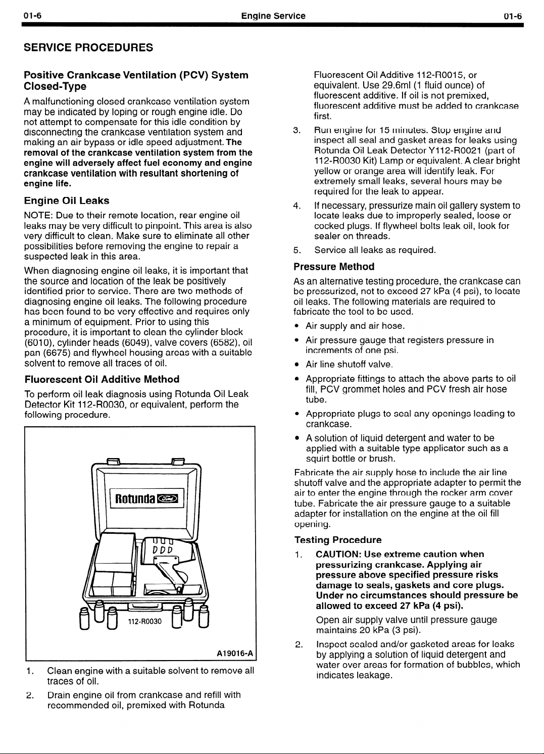
Fluorescent Oil Additive Method
To perform oil leak diagnosis using Rotunda Oil Leak
Detector Kit 112.R0030, or equivalent, perform the
followina procedure.
Al 9016-A
1. Clean engine with a suitable solvent to remove all
traces of oil.
2. Drain engine oil from crankcase and refill with
recommended oil, premixed with Rotunda
Fluorescent Oil Additive 112-ROOI 5, or
equivalent. Use 29.6ml (1 fluid ounce) of
fluorescent additive. If oil is not premixed,
fluorescent additive must be added to crankcase
first.
3. Run engine for 15 minutes. Stop engine and
inspect all seal and gasket areas for leaks using
Rotunda Oil Leak Detector Y 112-R0021 (part of
112-R0030 Kit) Lamp or equivalent. A clear bright
yellow or orange area will identify leak. For
extremely small leaks, several hours may be
required for the leak to appear.
4. If necessary, pressurize main oil gallery system to
locate leaks due to improperly sealed, loose or
cocked plugs. If flywheel bolts leak oil, look for
sealer on threads.
5. Service all leaks as required.
Pressure Method
As an alternative testing procedure, the crankcase can
be pressurized, not to exceed 27 kPa (4 psi), to locate
oil leaks. The following materials are required to
fabricate the tool to be used.
l
Air supply and air hose.
l
Air pressure gauge that registers pressure in
increments of one psi.
l
Air line shutoff valve.
l
Appropriate fittings to attach the above parts to oil
fill, PCV grommet holes and PCV fresh air hose
tube.
l
Appropriate plugs to seal any openings leading to
crankcase.
l
A solution of liquid detergent and water to be
applied with a suitable type applicator such as a
squirt bottle or brush.
Fabricate the air supply hose to include the air line
shutoff valve and the appropriate adapter to permit the
air to enter the engine through the rocker arm cover
tube. Fabricate the air pressure gauge to a suitable
adapter for installation on the engine at the oil fill
opening.
Testing Procedure
CAUTION: Use extreme caution when
1.
pressurizing crankcase. Applying air
pressure above specified pressure risks
damage to seals, gaskets and core plugs.
Under no circumstances should pressure be
allowed to exceed 27 kPa (4 psi).
Open air supply valve until pressure gauge
maintains 20 kPa (3 psi).
Inspect sealed and/or gasketed areas for leaks
2.
by applying a solution of liquid detergent and
water over areas for formation of bubbles, which
indicates leakage.

01-7
SERVICE PROCEDURES (Continued)
Engine Service
01-7
Leakage Points
Examine the following areas for oil leakage.
l
Rocker cover sealant or gaskets
l
Intake manifold gaskets/end seals
l
Cylinder head gaskets
l
Oil bypass filter (6714)
l
Oil level indicator (dipstick) tube connection
l
Oil pressure sensor (9278)
l
Cup plugs and/or pipe plugs at end of oil
passages
l
Oil pan gasket (6710)
l
Oil pan front and rear end seals
l
Crankshaft front seal (6700)
l
Crankshaft rear oil seal (6701)
l
Oil pump
l
Crankshaft rear oil seal (6701)
Air leakage in area around a crankshaft rear oil seal
(6701) does not necessarily indicate a rear seal leak.
However, if no other cause can be found for oil
leakage, it can be assumed that rear seal is the cause
of the oil leakage.
l
Rear main bearing cap parting line.
l
Rear main bearing cap and seals.
l
Flywheel mounting bolt holes.
l
Rear cup plugs and/or pipe plugs at the end of oil
passages.
Oil leaks at crimped seams in sheet metal parts and
cracks in cast or stamped parts can be detected when
pressurizing the crankcase.
Light foaming equally around rocker arm cover bolts
and crankshaft seals is not detrimental and no
corrections are required in such cases.
Compression Test
Compression Gauge Check
1.
Make sure oil in crankcase is of the correct
viscosity and at proper level, and battery (10655)
is properly charged. Operate the engine until it is
at normal operating temperature. Turn off ignition
switch (11572), then remove all spark plugs
(12405).
Set throttle plates in wide-open position.
Install a compression gauge such as Rotunda
Compression Tester 059-R0009, or equivalent, in
No. 1 cylinder.
Install an auxiliary starter switch in starting circuit.
With ignition switch (11572) in the OFF position,
and using auxiliary starter switch, crank engine at
least five compression strokes and record highest
reading. Note the approximate number of
compression strokes required to obtain the
highest reading.
5.
Repeat test on each cylinder, cranking the engine
approximately the same number of compression
strokes.
Test Results
The indicated compression pressures are considered
within specification if the lowest reading cylinder is
within 75 percent of the highest. Refer to the chart
below.
Compression Pressure Limit Chart
Maximum Minimum
psi
734 707 764 723 794 745 224 768
136 102 766 724 796 147 226 169
738 704 768 726 798 748 228 171
140 105 170 127 200 750 230 772
742 707 772 129 202 157 232 774
744 708 174 131 204 753 234 775
746 170 776 132 206 754 236 777
748 771 178 133 208 156 238 778
750 173 180 135 270 757 240 180
752 774 782 736 212 758 242 787
754 775 184 138 214 160 244 783
156 777 186 140 216 762 246 184
758 718 188 141 218 163 248 186
160 120 190 742 220 165 250 187
762 121 192 144 222 166
psi psi psi psi
Maximum Minimum Maximum
Minimum Maximum Minimum
psi psi
psi
I
,

01-8
-
SERVICE PROCEDURES (Continued)
Compression Readings - Interpreting
It is recommended the Compression Pressure Limit
Chart be used when checking cylinder compression so
that the lowest reading number is 75 percent of the
highest reading.
If one or more cylinders reads low, squirt
approximately one tablespoon of SAE 50 weight, or
equivalent, engine oil on top of the pistons in the low
reading cylinders. Repeat compression pressure
check on these cylinders.
1. If compression improves considerably, piston
rings are at fault.
2. If compression does not improve, valves are
sticking or seating poorly.
3. If two adjacent cylinders indicate low
compression pressures and squirting oil on
pistons does not increase compression, cause
may be a cylinder head gasket leak between
cylinders. Engine oil and/or coolant in cylinders
could result from this problem.
Example Readings
If, after checking the compression pressures in all
cylinders, it was found that the highest reading
obtained was 1351 kPa (196 psi) and the lowest
pressure reading was 1069 kPa (155 psi), the engine
is within specification and the compression is
considered satisfactory.
Cylinder Leakage Detector
When a cylinder produces a low reading, the use of
Rotunda Pressurization Kit 014-00705, or equivalent,
will be helpful in pinpointing the exact cause.
The leakage detector is inserted in the spark plug
hole, the piston is brought up to top dead center on the
compression stroke, and compressed air is admitted.
Once the combustion chamber is pressurized, a
special gauge will read the percentage of leakage.
Leakage exceeding 20 percent is considered
excessive.
While the air pressure is retained in the cylinder, listen
for the hiss of escaping air. A leak by the intake valve
(6507) will be audible in the carburetor. A leak by the
exhaust valve (6505) can be heard at the exhaust
pipe. Leakage past the rings will be audible at the
positive crankcase ventilation (PCV) connection. If air
is passing through a blown gasket to an adjacent
cylinder, the noise will be evident at the spark plug
hole of the cylinder into which the air is leaking. Cracks
in the cylinder block (6010), or gasket leakage into the
cooling system may be detected by a stream of
bubbles in the radiator (8005).
Engine Service
Oil Leak and Valve
The cylinder leakage detector can be used to test for
engine oil leaks and to check the valve seals for
leakage.
1. Plug all crankcase openings except the one used
2. Connect the detector to a crankcase opening.
3. Using a solution of liquid soap and water, brush
4.
Intake Manifold Vacuum Test
Bring the engine to normal operating temperature.
Connect Rotunda Vacuum/Pressure Tester
059-00008, or equivalent, to the intake manifold. Run
the engine at the specified idle speed.
The vacuum gauge should read between -51 and
-74 kPa (15 and 22 in-Hg) depending upon the engine
01-8
ROTUNDA
PRESSURIZATION
KIT
014-00705
A23452-A
Guide Seal Test
for connecting the leakage detector.
The oil level indicator tube (6754) is convenient.
Adjust the air pressure to approximately 34 kPa
(5 psi).
the solution along the gasket sealing surfaces
and bearing seals. Look for bubbles or foam.
Remove the spark plugs (12405) and rotate the
engine slowly with a wrench. Check for large
amounts of air escaping into the cylinders as
each intake and exhaust valve opens.
The spark plugs (12405) on the leaking cylinders
will probably show deposits of burned oil.
condition and the altitude at which the test is
performed. SUBTRACT 5.5 kPa FROM THE
SPECIFIED READING FOR EVERY 500 METERS
(1 in-Hg for every 1,000 feet) OF ELEVATION ABOVE
SEA LEVEL.

01-9
Engine Service
SERVICE PROCEDURES (Continued)
The reading should be quite steady. It may be
necessary to adjust the gauge damper control (where
used) if the needle is fluttering rapidly. Adjust damper
until needle moves easily without excessive flutter.
Vacuum Gauge Readings - Interpretation
A careful study of the vacuum gauge reading while the
engine is idling will help pinpoint trouble areas. Always
conduct other appropriate tests before arriving at a
final diagnostic decision. Remember that vacuum
gauge readings, although helpful, must be interpreted
with care.
Most vacuum gauges have a “normal” band indicated
on the aauae face.
VACUUM/
PRE
TE
059
A23453-A
Following are potential gauge readings. Some should
be considered as normal; others should be
investigated further.
1.
NORMAL READING: Needle between -51 and
-74 kPa (15 and 20 in-Hg) and holding steady.
2.
NORMAL READING DURING RAPID
ACCELERATION AND DECELERATION: When
engine is rapidly accelerated (dotted needle),
needle will drop to a low (not to 0) reading. When
throttle is suddenly released, the needle will snap
back up to a higher than normal figure.
NORMAL FOR HIGH LIFT CAM WITH LARGE
3.
OVERLAP: Needle will register as low as -50
kPa (15 in-Hg) but will be relatively steady. Some
oscillation is normal.
WORN RINGS OR DILUTED OIL: When engine
4.
is accelerated (dotted needle), needle drops to 0
kPa (0 in-Hg). Upon deceleration, needle runs
slightly above 74 kPa (22 in-Hg).
STICKING VALVE(S): When the needle (dotted)
5.
remains steady at a normal vacuum but
occasionally flicks (sharp, fast movement) down
and back about 13 kPa (4 in-Hg), one or more
valves may be sticking.
BURNED OR WARPED VALVES: A regular,
6.
evenly spaced, downscale flicking of the needle
indicates one or more burned or warped valves.
lnsuff icient hydraulic lash adjuster clearance will
also cause this action.
POOR VALVE SEATING: A small but regular
7.
downscale flicking can mean one or more valves
are not seating.
WORN VALVE GUIDES: When the needle
8.
oscillates (swings back and forth) over a 13 kPa
(4 in-Hg) range at idle speed, the valve guides
(6510) could be worn. As engine speed is
increased, the needle will become steady if the
guides are responsible.
WEAK VALVE SPRINGS: When the needle
9.
oscillation becomes more violent as engine rpm
is increased, weak valve springs (6513) are
indicated. The reading at idle could be relatively
steady.
LATE VALVE TIMING: A steady but low reading
10.
could be caused by late valve timing.
11. IGNITION TIMING RETARDING: Retarded
ignition timing will produce a steady but low
reading.
INSUFFICIENT SPARK PLUG GAP: When plugs
12.
are gapped too close, a regular, small pulsation
of the needle can occur.
13. INTAKE LEAK: A low, steady reading can be
caused by an intake manifold or carburetor
mounting flange gasket leak.
BLOWN HEAD GASKET A regular drop of
14.
approximately 33-50 kPa (1 O-l 5 in-Hg) can be
caused by a blown head gasket or warped headto-block mounting surface.
01-9
Al 0428-P
01-10 Engine Service 01-10
SERVICE PROCEDURES (Continued)
5.
15. RESTRICTED EXHAUST SYSTEM: When the
engine is first started and is idled, the reading
may be normal. But, as the engine rpm is
increased, back pressure caused by a clogged
exhaust pipe, etc., will cause the needle to slowly
drop to 0. The needle then may slowly rise.
Excessive exhaust clogging will cause the needle
to drop to a low point even if the engine is only
idled.
When vacuum leaks are indicated, search out and
correct the condition. Excess air leaking into the
system will upset the fuel mixture and cause
conditions such as rough idle, missing, or burned
valves. ALWAYS SERVICE VACUUM LEAKS.
Oil Consumption Test
The following diagnostic procedure is intended to be
used to determine the source of excessive internal oil
consumption.
1. Determine what is considered to be excessive oil
consumption. Note hours of engine service and
the following observations:
a. How many hours of engine use per 0.95 liter
(1 U.S. quart) of oil used?
b. How is the engine being used (e.g., sustained
high-speed operation, heavy loads, high
ambient temperature, etc.)?
c. What is the expected normal oil consumption?
2. Verify that the engine has no external oil leak as
described under Engine Oil Leaks in this section.
3. Verify that the oil level dipstick (6750) and oil
level indicator tube (6754) are unmodified and in
good condition. Verify that the oil level indicator
tube (6754) is properly seated in the block, and
the dipstick seats properly in the oil level indicator
tube (6754).
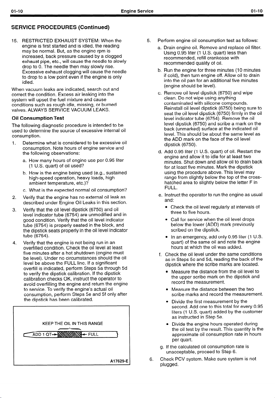
4. Verify that the engine is not being run in an
overfilled condition. Check the oil level at least
five minutes after a hot shutdown (engine must
be level). Under no circumstances should the oil
level be above the FULL line. If a significant
overfill is indicated, perform Steps 5a through 5d
to verify the dipstick calibration. If the dipstick
calibration checks OK, instruct the operator to
avoid overfilling the engine and return the engine
to service. To verify the engine’s actual oil
consumption, perform Steps 5e and 5f only after
the dipstick has been calibrated.
KEEP THE OIL IN THIS RANGE
Al 7629-E
Perform engine oil consumption test as follows:
a. Drain engine oil. Remove and replace oil filter.
Using 0.95 liter (1 U.S. quart) less than
recommended, refill crankcase with
recommended quality of oil.
b. Run the engine for three minutes (10 minutes
if cold), then turn engine off. Allow oil to drain
into the oil pan for an additional five minutes
(engine should be level).
c. Remove oil level dipstick (6750) and wipe
clean. Do not wipe using anything
contaminated with silicone compounds.
Reinstall oil level dipstick (6750) being sure to
seat the oil level dipstick (6750) firmly in the oil
level indicator tube (6754). Remove the oil
level dipstick (6750) and scribe a mark on the
back (unmarked) surface at the indicated oil
level. This should be about the same level as
the ADD mark on the face of the oil level
dipstick (6750).
d. Add 0.95 liter (1 U.S. quart) of oil. Restart the
engine and allow it to idle for at least two
minutes. Shut down and allow oil to drain back
for at least five minutes. Mark the dipstick
using the procedure above. This level may
range from slightly below the top of the crosshatched area to slightly below the letter F in
FULL.
e. Instruct the operator to run the engine as usual
and:
l
Check the oil level regularly at intervals of
three to five hours.
l
Call for service when the oil level drops
below the lower (ADD) mark previously
scribed on the dipstick.
l
In an emergency, add only 0.95 liter
quart) of the same oil and note the engine
hours at which the oil was added.
f. Check the oil level under the same conditions
as in Steps 5c and 5d, reading the back of the
dipstick where the scribe marks are located.
l
Measure the distance from the oil level to
the upper scribe mark on the dipstick and
record the measurement.
l
Measure the distance between the two
scribe marks and record the measurement.
l
Divide the first measurement by the
second. Add one to this total for every 0.95
liters (1 U.S. quart) added by the customer
as instructed in Step 5e.
l
Divide the engine hours operated during
the oil test by the result. This quantity is the
approximate oil consumption rate in hours
per quart.
g. If the calculated oil consumption rate is
unacceptable, proceed to Step 6.
Check PCV system. Make sure system is not
6.
plugged.
(1
U.S.
01-11
SERVICE PROCEDURES (Continued)
Check for plugged oil drain-back holes in cylinder
7.
heads (6049) and cylinder block (6010).
If condition still exists, perform a cylinder
compression test as described in this section,
and/or perform a cylinder leak detection test with
Rotunda Pressurization Kit 014-00705, or
equivalent. This can be helpful in determining the
source of oil consumption, as an example,
valves, piston rings, etc.
Check valve guides (6510) for excessive
clearance. Replace all valve stem seals (6A517)
after correct valve guide clearance has been
verified.
IO.
NOTE: After checking for worn parts, if it is
determined parts should be replaced, make sure
correct replacement parts are used. Worn or
damaged internal engine components can cause
excessive oil consumption. Small deposits of oil
on tip of spark plugs (12405) can be a clue to
internal oil consumption. If internal oil
consumption still persists, proceed as follows:
a. Remove intake manifold(s), cylinder heads
(6049), oil pan and oil pump.
b. Check piston ring clearance, ring gap and ring
orientation as outlined in this section. Service
as required.
c. Check for excessive bearing clearance as
outlined in this section. Service as required.
Perform Step 5 again to verify that the oil
11.
consumption concern has been resolved.
Oil Pressure Test
SPECIAL SERVICE TOOL(S) REQUIRED
Description
1 Engine Oil Pressure Gauge
1.
Disconnect and remove the oil pressure sensor
(9278) from the engine.
2.
Connect an Engine Oil Pressure Gauge
T73L-6600-A and Transmission Test Adapter
D87C-77000-A, or equivalent, to the oil pressure
sensor screw port.
Run the engine until normal operating
3.
temperature is reached.
4.
Run the engine at 3,000 rpm and record the
gauge reading.
5.
The oil pressure should be:
l
250-490 kPa (36-71 psi) at 3,000 rpm.
6.
If the pressure is not within specification, check
the following possible sources:
l
Insufficient oil
l
Oil leakage
l
Worn or damaged oil pump (6621)
l
Clogged oil pump screen cover and tube
(6622)
l
Excessive main bearing clearance
0 Excessive connecting rod bearing clearance
Tool Number
I
1 T73L-6600-A
Engine Service
-
I
I
01-l 1
ValveTrain Analysis
- Static (Engine Off)
Rocker Arm/Camshaft Follower Cover Removed
NOTE: Static Valve Train Analysis, with the engine off,
is to be performed before Dynamic Valve Train
Analysis, which is performed with engine running.
NOTE: Remove valve cover (6582) as outlined in this
section.
Check for damaged and/or severely worn parts,
correct assembly, and use of correct parts by
proceeding with the static engine analysis.
Rocker/Camshaft Follower Arm Assemblies
l
Check for loose mounting bolts, studs and nuts.
l
Check for a plugged oil feed in the rocker arm
(6564), or cylinder head (6049).
Camshaft - 2.3L Engine
Inspect camshaft, camshaft lobes and journals for
excessive wear or scoring. Repair or replace as
necessary.
Valve Springs
l
Check for broken or damaged parts.
Valve Spring Retainer and Valve Spring Keys
l
Check for proper seating of valve spring retainer
keys (6518) on valve stem and in valve spring
retainer (6514).
Valves and Cylinder Head
l
Check for signs of improper head gasket (6051)
installation, such as the shape of the head and
block and shape of the gasket not matching.
l
Check for signs of cylinder head gasket leakage
such as coolant or oil leaking between the cylinder
block (6010) and cylinder head (6049).
l
Check for plugged oil drain-back holes.
l
Check for worn or damaged valve tips.
l
Check for missing or damaged intake and exhaust
valve stem seals (6A517).
l
Check valve clearance.
0 Check installed spring height.
l
Check for missing or worn valve spring seats, if
equipped.
Intake Valve Cleaning (Valves Installed)
Cleaning and Inspection
NOTE: The intake valve cleaning procedure is to be
used if there is a concern with engine hesitation, rough
idle, long crank times, and stall at idle and engine
engagement after cold starts.
NOTE: Many fluids are available to clean carburetors.
Some cleaning fluids also claim to remove intake valve
deposits (IVD). Engineering evaluation of these fluids
indicates no ability to remove the intake valve
deposits. If engine performance concerns have been
affected by cleaning fluids, it is most likely due to
cleanup of carburetor deposits. IVD is more difficult to

01-12
SERVICE PROCEDURES (Continued)
Engine Service
01-l 2
remove than carburetor deposits. IVD must be
COMPLETELY removed to restore cold start and
normal engine performance.
CAUTION:The overuse of cleaning fluids may
cause engine damage not covered under warranty.
CAUTION: Only walnut shell blasting using
Rotunda 014-00975 Carbon Blaster and
Automotive Borescope, or equivalent, is
recommended for removing carbon from engine
valves with the engine assembled. Other abrasives
may cause engine damage on start-up if not
completely removed.
1.
Perform engine inspection of vacuum lines and
wiring.
2. Perform normal engine diagnostics. Check fuel
and ignition systems.
3. If normal diagnostics have not resolved the
engine performance concerns, proceed with the
following IVD inspection steps.
4.
Remove any two spark plugs (12405).
5.
CAUTION: Do not bump the engine with the
remote starter switch or ignition switch with
the borescope in the spark plug hole or
attempt to view the valve while rotating the
engine. Damage to the borescope or engine
may result.
Use a remote starter switch to bump the engine
over until the intake valve (6507) is fully open in
the cylinder to be inspected.
6.
CAUTION: Do not power the borescope light
source from a vehicle battery (10655) while it
is being charged. For example, if the engine is
running or the battery (10655) is connected to
a charger, the lamp may fail.
Using the Rotunda Carbon Blaster and
Automotive Borescope 014-00975, or equivalent
automotive borescope, inspect the backside of
the intake valves (6507) through the spark plug
holes for the presence of carbon deposits.
Compare the deposits with the deposit rating
system chart. If any of the intake valves (6507)
appear to have a carbon deposit level of 7 or less
(lower number rating), intake valve cleaning is
required. If no carbon deposits are seen or the
deposit level is 8 or cleaner, the drive concern
may be the result of low volatility fuel.
Intake Valve Deposit Rating System
9
6
8
5
7
4
3
2
1
A239094

01-13
SERVICE PROCEDURES (Continued)
7.
Remove the intake manifold assembly as
outlined in Section 02.
8.
Remove flex hose and manifold adapter from the
hand-held vacuum included with the Rotunda
014-00975 Carbon Blaster and Automotive
Borescope. Insert tapered end of vacuum hose
into intake port of cylinder head using a twisting
motion to ensure a tight fit.
9.
NOTE: Detailed written instructions and a
procedural video tape are included with the
Rotunda 014-00975 Carbon Blaster and
Automotive Borescope. Perform the intake valve
carbon cleaning procedure, using the Rotunda
014-00975 Carbon Blaster or equivalent. The
intake valves should be in the closed position.
Cleaning takes approximately 1 to 1 -i/2 minutes
per valve.
Confirm the intake valve (6507) is clean using
10
Rotunda 014-00975, or equivalent automotive
borescope.
11
Using a remote starter switch, bump the engine
over until the remaining intake valves to be
cleaned, are in the closed position, and clean
them as outlined above.
13
Install the intake manifold as outlined in Section
. -.
02.
Camshaft Lobe Lift, 2.3L Overhead Camshaft
Engine (Camshaft Installed)
This procedure is for checking lift with the camshaft
(6251) installed. For checking with camshaft removed,
refer to service procedure, Cam Lobe Lift (Camshaft
Removed) in this section.
Check the lift of each lobe in
make a note of the readings.
1.
Remove valve cover (6582) as outlined in
Section 02.
2.
Remove spark plugs (12405) as outlined in
Section 02.
3.
Inspect the camshaft lobes for scoring and signs
of abnormal wear.
Lobe pitting, except in the general area of the
lobe toe, is not detrimental to the operation of the
camshaft. The camshaft should not be replaced
unless lobe lift loss has exceeded the
specifications or pitting has occurred in the lobe
lift area.
4.
Inspect for signs of camshaft bearing wear.
5.
Using ratchet handle and socket on vibration
damper bolt, rotate engine so cylinder number
one exhaust valve is fully open (heel of cam at
top).
6.
Install TOOL-4201-C, or equivalent, Dial Indicator
with Bracketry, so tip of dial indicator is on heel of
cam.
7.
Zero dial indicator.
8.
Slowly rotate engine until tip of dial indicator is on
tip of cam and read. This is cam lift.
consecutive order and
Engine Service
9.
Hydraulic Valve Tappet/Lash Adjuster
The hydraulic lash adjusters used in the overhead cam
2.3L engine are zero-lash hydraulic devices similar in
construction and operation to the hydraulic valve
tappets (6500) used on push rod engines. They are
cleaned, inspected and checked in the same manner
as hydraulic valve tappets The instructions below
apply equally to the lash adjuster and the valve tappet.
Hydraulic tappet noise may be caused by any of the
following:
1. Excessive collapsed tappet gap
2.
3.
4.
5.
6.
Excessive collapsed tappet gap may be caused by
loose valve train parts such as wear of tappet face,
worn roller finger follower (6529), or worn valve tip.
With valve tappet (6500) collapsed, check gap
between valve tip and roller finger follower to
determine if any other valve train parts are damaged,
or worn. Replace any worn or damaged parts.
A sticking tappet plunger may be caused by dirt, chips,
or varnish inside the tappet. The sticking can be
corrected by disassembling the valve tappet and
removing the dirt, chips or varnish that are causing the
condition.
A tappet check valve that is not functional may be
caused by an obstruction such as dirt or chips
preventing it from closing when operated, or it may be
caused by a broken check valve spring within the
tappet.
Air bubbles in the lubrication system will prevent the
valve tappet from supporting the valve spring load and
may be caused by an oil level that is too high or too
low, or by air being drawn into the system through a
hole, crack or leaking gasket on the oil pump screen
cover and tube (6622).
01-13
Write down cam lift and repeat for the rest of the
cam lobes. If any lobe’s lift is below the minimum
lift specified in Section 02, replace the camshaft.
Sticking tappet plunger
Tappet check valve not functioning properly
Air in lubrication system
Leak-down rate too rapid
Excessive valve guide wear
If the leakdown time is below the specified time for
used valve tappets, noisy operation may result. If no
other cause for noisy valve tappets can be found, the
leakdown rate should be checked, and any outside the
specification should be replaced.
Camshaft End Play
CAUTION: Prying against the camshaft sprocket
(6256) with valve train load on the camshaft
(6251), can break or damage the camshaft
sprocket. Therefore, on 2.3L engines, remove the
cam followers as outlined in Section 02.
After checking camshaft end play, reinstall or retighten
valve train components as outlined in Section 02.

01-14
SERVICE PROCEDURES (Continued)
Engine Service
01-14
Timing Belt (2.3L)
NOTE: If the timing belt has greater than 3,000 hours
of use, the timing belt will need to be replaced. Refer
to Section 02 for service procedures.
Camshaft Timing and Cylinder Identification
(CID) Timing Check
1.
Remove the rubber access cap from the outer
timing cover to expose the camshaft sprocket.
2.
Rotate the crankshaft so that number one
cylinder is at Top Dead Center (TDC) of the
compression stroke. TDC will be indicated when
the two timing marks are aligned:
a. The timing mark on the crankshaft damper
assembly will align with “TC” on the outer
timing cover.
b. The triangular timing mark on the camshaft
sprocket will align with the timing mark on the
inner timing cover.
3. If the triangle timing mark cannot be seen through
the access hole of the outer timing cover, rotate
the crankshaft one revolution. TDC will be
indicated when the two timing marks are aligned.
4. If the triangle timing mark cannot be properly
aligned, set the timing mark of the crankshaft
damper assemblv on “TC” of the outer timing
cover. Remove the crankshaft damper assembly
and outer timing cover as outlined in Section 02.
VIEW IN CIRCLE A
C
0
Item
Part
Number
6256
N801658-S
6K282
6K254
6303
6306
9
d
8
0
Description
Camshaft Sprocket
Pointer Triangle (Part of
Camshaft Sprocket)
Pointer Triangle (on Inner
Timing Belt Cover)
Stud, M8 x 1.25
Spring Pivot Bolt
Stud (Part of 6K254)
Timing Belt Tensioner
Crankshaft
Crankshaft Sprocket
Item
IO
11
12
13
A
B
C
D
E
NOTE:
Part
Number
N806700-S
N800112-52
B
TO PAN
RAIL
VIEW IN
CIRCLE 8
Description
Key
Adjusting Bolt, M8 - 1.25 x 20
Pointer Line (Part of 6019)
Pointer Circle (on 6306)
Tighten to 20-30 Nom
(15-22 Lb-Ft) (See Text)
Tighten to 40-55 N*m
(30-40 Lb-Ft) (See Text)
Tighten to 35-45 Nom
(26-33 Lb-Ft) (See Text)
Direction of Rotation
29”
PPDA21101-6
J

01-15
SERVICE PROCEDURES (Continued)
Engine Service
0145
Crankshaft End Play
Install Dial Indicator with Bracketry TOOL-4201 -C,
1.
or equivalent, so contact point rests against the
end of the crankshaft post and indicator axis is
parallel to crankshaft axis.
2. Force crankshaft (6303) toward rear of engine.
INDICATOR
STYLUS AGAINST
AND PARALLEL
A211234
Zero dial indicator. Push crankshaft (6303)
3.
forward and note reading on dial.
4. If the end play exceeds the wear limit listed in the
specification section, replace the thrust bearing.
Inspect the crankshaft for damage to the thrust
face before installing the new bearing. If the end
play is less than the minimum limit, inspect the
thrust bearing faces for scratches, burrs, nicks, or
dirt. If the thrust faces are not damaged or dirty,
the main thrust bearing may not be aligned
properly. Lubricate and install the thrust bearing
and align the faces, following Main Bearing
Replacement procedure in the appropriate
engine section. Check crankshaft end play.
.
Connecting Rod Side Clearance
1.
Install Rotunda Dial Indicator with Bracketry
TOOL-4201-C, or equivalent, so that the contact
point rests against the connecting rod cap.
Pull cap toward front of engine and zero the dial
2.
indicator.
3. Push cap toward rear of engine and observe
amount of side clearance on dial indicator.
4. If side clearance exceeds specification, replace
connecting rod and cap. Refer to the specification
section.
If side clearance is less than specification,
remove rod and cap and inspect for scratches,
burrs, nicks or dirt between crankshaft and
connecting rod.
Cylinder Block
Cleaning and Inspection
If the engine has been removed and disassembled,
remove all core plugs and pipe plugs. Clean the
cylinder block (6010) using solvent, preferably in a hot
tank. Follow all safety and environmental precautions
with regard to the solvent. Make sure all oil and dirt is
cleaned from the cylinder block.
Make sure all oil passageways are clean. A rifle-
cleaning brush is useful for this purpose.
Use a long, thin screwdriver to scrape the bottom of
the water jackets through the openings in the top deck
to make sure all scale and deposits are removed. Most
engines have a “dead spot” at the back of the block
where the coolant makes a U-turn and drops any
deposits. If the water jackets are not thoroughly
cleaned, overheating will result.
Cylinder Block Distortion
Cylinder block distortion is rare because cylinder
blocks are normalized after casting, and before
machining, to relieve internal stresses from the casting
process.
The most probable cause of cylinder block distortion
would be extreme overheating which would probably
be accompanied by other damage such as scored
bearings or cylinder walls, warped cylinder heads
(6049) and possible cylinder block cracks.
Cylinder Head Deck Flatness
Place a straightedge across the cylinder head
1.
deck in three positions and check for any gaps
between the straightedge and the deck with a
feeler gauge. The deck should be flat within
0.76mm (0.003 in.) over 152mm (6 inches) and
0.152mm (0.006 in.) overall.
If necessary, resurface or replace cylinder block
2.
(6010).
Main Bearing Bore Alignment
Main bearing bore misalignment may be suspected in
cases of premature bearing wear if one bearing wears
considerably more than the others or bearings wear
cone-shaped.
NOTE: Bearings are not available with oversize
outside diameters to allow line boring.
If bearing misalignment is suspected:
Acquire a gauge bar the same diameter as the
1.
crankshaft journals and straight within 0.076mm
(0.003 in.).
Put a thin coating of Prussian Blue or similar die
2.
on gauge bar.
Insert good bearings in block.
3.
Insert gauge bar in bearings and rotate one turn.
4.
Remove gauge bar.
5.
Inspect bearings. Blue die should be deposited
6.
evenly on all bearings. If die appears on only one
side or bottom of bearing or not at all, block is
distorted and should be replaced.
01-16
SERVICE PROCEDURES (Continued)
Engine Service
01-16
Cylinder Walls, Refinishing
Cleaning
If the entire engine has NOT been disassembled,
clean the individual cylinder bore(s) with a cloth
soaked in solvent. Dry with a clean, lint-free cloth.
If the entire engine HAS been disassembled, refer to
Cylinder Block Cleaning in this section.
After any cylinder bore service operation, such as
honing or deglazing, clean the bore(s) with soap or
detergent and water. Then thoroughly rinse the bore(s)
with clean water to remove the soap or detergent, and
wipe the bore(s) dry with a clean lint-free cloth. Finally,
wipe the bore(s) with a clean cloth dipped in
X0-1 OW30-QSP or -DSP, or equivalent, motor oil
meeting Ford specification ESE-M2C153-E.
Inspection
Before removing the piston (6108):
1. Check the amount of ridge at the top of the bore.
A thick ridge is a sign of considerable wear.
2. Look for signs of coolant in the bore, especially
rust on the bore surface indicating possible
leaking head gasket or a crack in the cylinder
bore.
3. Check the top of the piston for possible oversize.
If oversize pistons have been installed, the
oversize will be stamped in the top of the piston
(6110).
After the piston is removed and the bore cleaned:
4.
Look for scoring. These are parallel gouges
usually on the piston thrust side, that is, at right
angles to the piston pin. If scored, the cylinder will
have to be refinished.
5.
Look for cracks. If unsure about a crack, tiny
cracks may be detected by coating the bore with
a mixture of 25 percent kerosene and 75 percent
light engine oil. Wipe the bore dry and
immediately apply a coating of zinc oxide
dissolved in wood alcohol. Do not use rubbing
alcohol as a substitute. If cracks are present, the
coating will become discolored at the damaged
area. Replace the cylinder block if it is cracked.
Magnafluxing may also be used.
6.
Check for cylinder wall glazing. When refinished,
the cylinder bore is given a slightly rough finish
with a cylinder hone to help seat the new piston
rings. This finish is worn away as the rings and
cylinder bore “mate” and the bore becomes
glassy smooth. If the engine has been run
enough for this to have happened, the cylinder
will at least have to be honed to seat the new
rings on the piston. New rings should be installed
when the piston is removed and reinstalled
because piston rings are given a special finish by
the factory to help them wear-in and seat. In
seating, the special finish is worn off. Reusing
piston rings will result in high oil consumption.
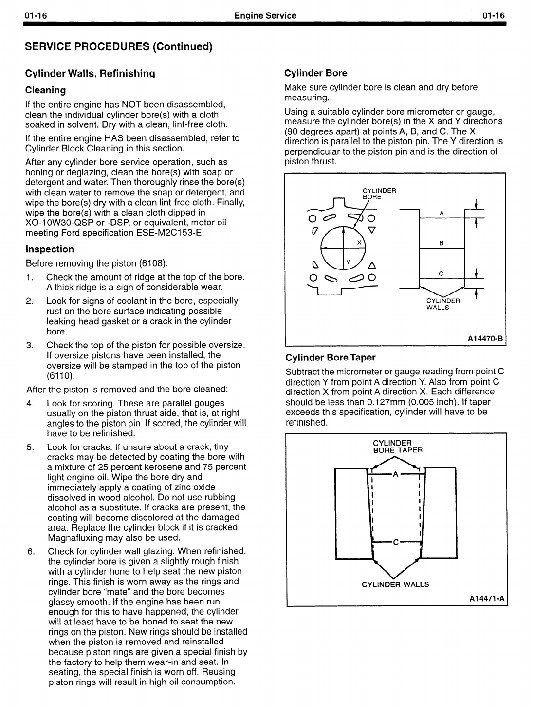
Cylinder Bore
Make sure cylinder bore is clean and dry before
measuring.
Using a suitable cylinder bore micrometer or gauge,
measure the cylinder bore(s) in the X and Y directions
(90 degrees apart) at points A, B, and C. The X
direction is parallel to the piston pin. The Y direction is
perpendicular to the piston pin and is the direction of
piston thrust.
CYLINDER
.
CYLINDER
WALLS
A
B
1
.
t
Al 4470-B
Cylinder Bore Taper
Subtract the micrometer or gauge reading from point C
direction Y from point A direction Y. Also from point C
direction X from point A direction X. Each difference
should be less than 0.127mm (0.005 inch). If taper
exceeds this specification, cylinder will have to be
refinished.
CYLINDER
BORE TAPER
CYLINDER WALLS
Al 4471 -A

01-17 Engine Service
SERVICE PROCEDURES (Continued)
Cylinder Out-of-Round
Subtract the reading in direction X (non-thrust) from
direction Y (thrust side) at all points A, B, and C. All
readings should be less than 0.127mm (0.005 inch). If
out-of-round exceeds this specification, cylinder will
have to be refinished.
FRONT
OF
Egz
NDER
CYLI
BORE
A23876-A
Cylinder Bore Diameter
1.
Measure the diameter of the piston on the thrust
side at right angles to the piston pin - 254mm
(1 .OO inch) below the oil ring groove.
PISTON
GR
A24225-A
2. Measure the cylinder bore diameter at right
angles to the piston pin at points A, B, and C as
described under cylinder taper.
Subtract the piston diameter from the cylinder
3.
bore diameter. The difference should not exceed
the maximum piston-to-bore clearance found in
Specifications in Section 02.
:I3
Cylinder Wall Honing
Hone the cylinder bore:
l
l
1. Measure the diameter of the piston on the thrust
2.
3.
4.
01-17
PISTON
6108
PISTON-TO-CYLINDER 1 f-CLEARANCE
Al 4479-B
When reinstalling a piston with new rings.
To resize a cylinder to accept a service parts piston
going into it.
side at right angles to the piston pin - 254mm
(1 .OO inch) below the oil ring groove.
Measure the cylinder bore diameter at right
angles to the piston pin at points A, B, and C as
described under cylinder taper.
Subtract the piston diameter from the maximum
cylinder bore diameter to determine the
maximum amount of material that can be
removed.
Hone the cylinder according to the hone
manufacturer’s instructions to obtain the proper
bore surface finish of 18-38 RMS.
l
Keep the hone moving up and down to
achieve the proper crosshatch pattern.
l
Measure frequently to make sure that you do
not remove too much of the cylinder wall,
creating excess clearance.
01-18
SERVICE PROCEDURES (Continued)
Engine Service
01-18
Engine Block Plugs
SPECIAL SERVICE TOOL(S) REQUIRED
Description
Impact Slide Hammer
Impact Slide Hammer
Removal and Installation
To remove a large core plug, drill a 12.70mm (l/2 inch)
hole in the center of the plug and remove with an
Impact Slide Hammer T59L-100-B or T50T-100-A or
pry it out with a large drift punch. On a small core plug,
drill a 6.35mm (l/4 inch) hole in the center of the plug
and pry it out with a small pin punch. Clean and
inspect the plug bore.
Prior to installing a core plug, the plug bore should be
inspected for any damage that would interfere with the
proper sealing of the plug. If the bore is damaged, it
will be necessary to true the surface by boring for the
next specified oversize plug.
Oversize plugs are identified by the OS stamped in the
flat located on the cup side of the plug.
Coat the plug and/or bore lightly with an oil-resistant
(oil galley) Stud and Bearing Mount EOAZ-19554-BA,
or equivalent, meeting Ford specification
WSK-M2G349-Al or Threadlock 262 E2FZ-19554-B,
or equivalent, meeting Ford specification
WSK-M2G351 -A6, and install it following the
procedure for cup-type or expansion-type below:
Tool Number
T59L-100-B
T50T-100-A
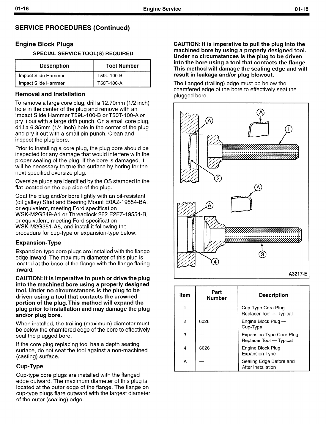
CAUTION: It is imperative to pull the plug into the
machined bore by using a properly designed tool.
Under no circumstances is the plug to be driven
into the bore using a tool that contacts the flange.
This method will damage the sealing edge and will
result in leakage and/or plug blowout.
The flanged (trailing) edge must be below the
chamfered edge of the bore to effectively seal the
plugged bore.
Expansion-Type
Expansion-type core plugs are installed with the flange
edge inward. The maximum diameter of this plug is
located at the base of the flange with the flange flaring
inward.
CAUTION: It is imperative to push or drive the plug
into the machined bore using a properly designed
tool. Under no circumstances is the plug to be
driven using a tool that contacts the crowned
portion of the plug.This method will expand the
plug prior to installation and may damage the plug
and/or plug bore.
When installed, the trailing (maximum) diameter must
be below the chamfered edge of the bore to effectively
seal the plugged bore.
If the core plug replacing tool has a depth seating
surface, do not seat the tool against a non-machined
(casting) surface.
Cup-Type
Cup-type core plugs are installed with the flanged
edge outward. The maximum diameter of this plug is
located at the outer edge of the flange. The flange on
cup-type plugs flare outward with the largest diameter
of the outer (sealing) edge.
Item
1 -
2 6026
3 -
4 6026
A -
Part
Number
A321 7-E
Description
Cup-Type Core Plug
Replacer Tool - Typical
Engine Block Plug Cup-Type
Expansion-Type Core Plug
Replacer Tool - Typical
Engine Block Plug -
Expansion-Type
Sealing Edge Before and
After Installation

01-19
SERVICE PROCEDURES (Continued)
Enaine Service
01-19
Crankshaft Main and Connecting Rod
Bearings
Cleaning
NOTE: Do not scrape gum or varnish deposits from
the bearing shells.
Bearings that are to be reused should be identified so
they can be installed in their original locations.
Clean the bearing inserts and caps thoroughly in
solvent, and dry them with compressed air.
Inspection
Inspect each bearing carefully. Bearings that have a
scored, chipped or worn surface should be replaced.
Typical examples of unsatisfactory bearings and their
causes are shown in the illustration. The copper lead
bearing base may be visible through the bearing
overlay. If the base showing is less than 20 percent of
the total area, the bearing is not excessively worn. It is
not necessary to replace the bearing if the bearing
clearance is within recommended limits. Check the
clearance of bearings that appear to be satisfactory
with Plastigage@ as described in this section.
n
Item
1
A -
B -
c - Dirt Scratching, lmbedding
D - Overlay Wiped Out - Lack of
E -
F G - Overlay Gone from Mating
Part
Number
6333 Connecting Rod Bearing
Description
Fatigue Failure - Craters or
Pockets
Improper Seating - Bright
(Polished) Sections
Oil or Improper Clearance
Hourglass -
from Edges
Radius Ride
Edge, One Side Only. Rod Cap
Shift.
Overlay Gone
Crankshaft Main or Connecting Rod Bearings
- Fitting Plastigage@ Method
1.
Clean crankshaft journals. Inspect journals and
thrust faces for nicks, burrs or roughness that
would cause premature bearing wear.
replacing standard bearings with new bearings,
it is good practice to fit bearing to minimum
specified clearance.
be obtained with a standard bearing, try a
0.050mm (0.002-inch) undersize bearing set to
obtain proper clearance.
2.
CAUTION: Do not position jack under crankshaft
pulley. Crankshaft post damage will result.
If fitting main bearing in-equipment, position a
jack under counterweight adjoining bearing which
is being checked. Support crankshaft (6303) with
jack so its weight will not compress Plastigage@
and cause an incorrect reading.
Place a piece of Plastigage@ D81 L-6002-B, or
3.
equivalent, on bearing surface across full width of
bearing cup and about 6.35mm (l/4 inch) off
center.
If desired clearance cannot
When
1
00
A2333843
01-20
Engine Service
SERVICE PROCEDURES (Continued)
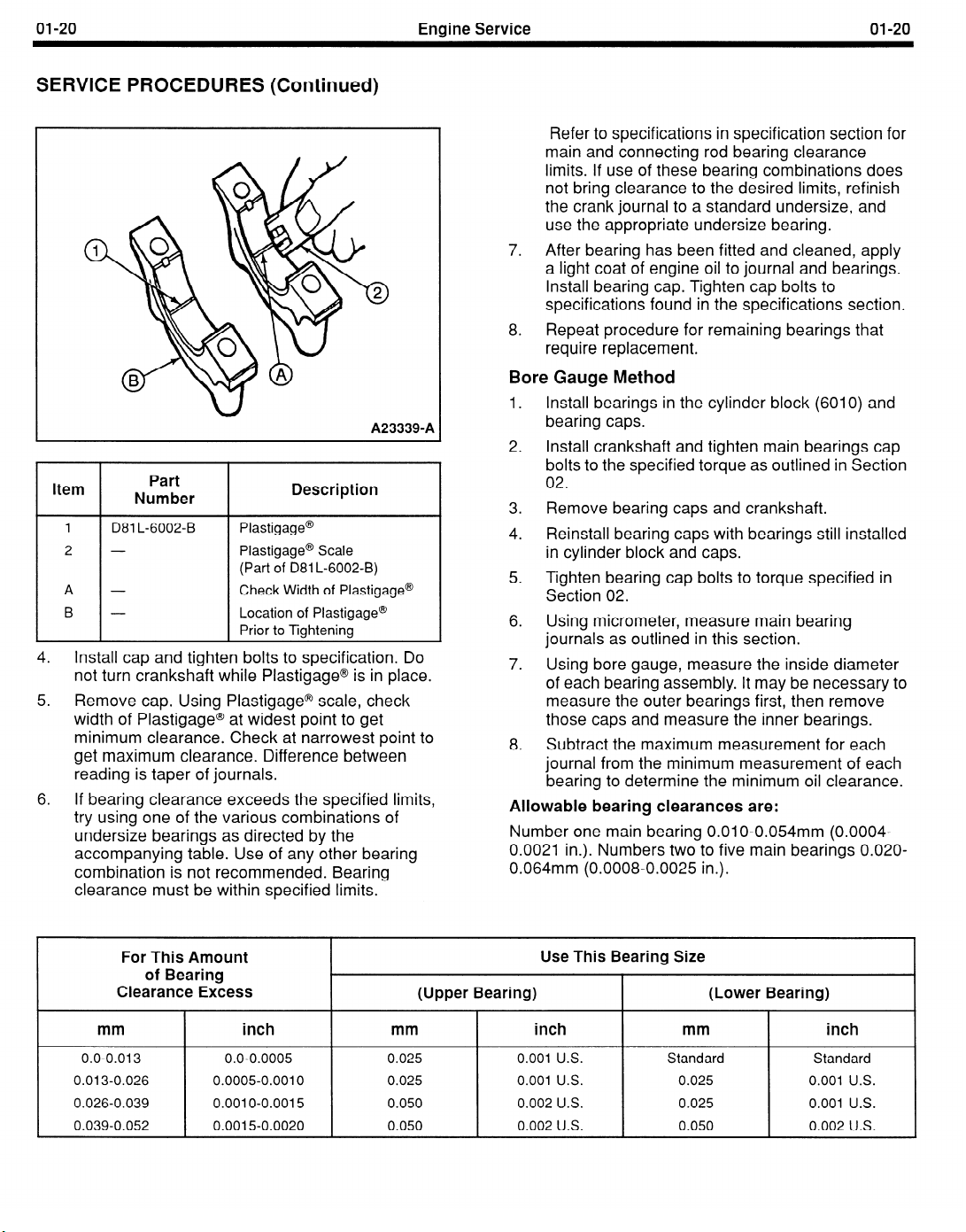
A233390A
Item
1
2 -
A - Check Width of Plastigage@
B - Location of Plastigage@
4.
Install cap and tighten bolts to specification. Do
Part
Number
D81 L-6002-B
not turn crankshaft while Plastigage@ is in place.
5. Remove cap. Using Plastigage@ scale, check
width of Plastigage@ at widest point to get
minimum clearance. Check at narrowest point to
get maximum clearance. Difference between
reading is taper of journals.
6. If bearing clearance exceeds the specified limits,
try using one of the various combinations of
undersize bearings as directed by the
accompanying table. Use of any other bearing
combination is not recommended. Bearing
clearance must be within specified limits.
Description
Plastigage@
Plastigage@ Scale
(Part of 081 L-6002-B)
Prior to Tightening
01-20
Refer to specifications in specification section for
main and connecting rod bearing clearance
limits. If use of these bearing combinations does
not bring clearance to the desired limits, refinish
the crank journal to a standard undersize, and
use the appropriate undersize bearing.
After bearing has been fitted and cleaned, apply
7.
a light coat of engine oil to journal and bearings.
Install bearing cap. Tighten cap bolts to
specifications found in the specifications section.
8. Repeat procedure for remaining bearings that
require replacement.
Bore Gauge Method
1.
Install bearings in the cylinder block (6010) and
bearing caps.
2.
Install crankshaft and tighten main bearings cap
bolts to the specified torque as outlined in Section
02.
Remove bearing caps and crankshaft.
3.
Reinstall bearing caps with bearings still installed
4.
in cylinder block and caps.
Tighten bearing cap bolts to torque specified in
5.
Section 02.
Using micrometer, measure main bearing
6.
journals as outlined in this section.
Using bore gauge, measure the inside diameter
7.
of each bearing assembly. It may be necessary to
measure the outer bearings first, then remove
those caps and measure the inner bearings.
8.
Subtract the maximum measurement for each
journal from the minimum measurement of each
bearing to determine the minimum oil clearance.
Allowable bearing clearances are:
Number one main bearing 0.01 O-0.054mm (0.0004-
0.0021 in.). Numbers two to five main bearings 0.020-
0.064mm (0.0008-0.0025 in.).
For This Amount
of Bearing
Clearance Excess
mm
0.0-0.013
0.013-0.026 0.0005-0.0010
0.026-0.039
0.039-0.052 0.0015-0.0020
,
inch
0.0-0.0005
0.0010-0.0015
Use This Bearing Size
(Upper Bearing)
mm inch
0.025 0.001
0.025
0.050 0.002
0.050
0.001 U.S.
0.002 U.S.
mm
U.S. Standard
0.025 0.001 U.S.
U.S. 0.025
0.050 0.002 U.S.
(Lower Bearing)
inch
Standard
0.001 U.S.

01-21
SERVICE PROCEDURES (Continued)
Engine Service
01-21
Crankshaft
Cleaning
CAUTION: Handle the crankshaft (6303) with care
to avoid possible damage to the finished surfaces.
Clean the crankshaft with solvent, then blow out all oil
passages with compressed air.
Inspection
Measure the diameter of each journal in at least four
places to determine an out-of-round, taper or
undersize condition. For specifications, refer to the
specification section.
Crankshaft Runout
NOTE: Check crankshaft journals for out-of-round
before checking runout, or an out-of-round condition
on the center journal could be confused as excess
runout.
1.
Set V-blocks on surface plate and set crankshaft
on V-blocks supported on the outer two main
bearing journals.
2. Set up TOOL-4201 -C, or equivalent, Dial
Indicator with Bracketry to measure runout on
center main bearing journal.
3. Zero dial indicator.
4. Slowly rotate crankshaft one revolution and
record highest and lowest readings.
5. Crankshaft runout should not exceed 0.050mm
(0.002 in.). If crankshaft runout is excessive,
replace crankshaft.
MAGNETIC
BASE
DIAL
INDICATOR
D78P-4201 -B
k
I
V-BLOCKS
Crankshaft End Play
Refer to crankshaft end play elsewhere in this section.
Crankshaft must be installed in block with the bearings
that will be used, but without connecting rods, pistons,
or flywheel (6375) installed to check end play.
Al 6693-B
Crankshaft Main Journals and Connecting Rod
Journals
Inspect the main journal and crankpin journal
diameters. Measure the diameter of each journal at
two different points in the directions as shown.
JOURNAL
Al 4474-A
Refer to Section 02 for crankshaft journal
specifications.
Journals Refinishing
NOTE: Polish direction is clockwise as viewed from
the front of the crankshaft.
Dress minor imperfections such as scores, nicks or
burrs with an oil stone.
If journals are severely marred or exceed service limits
for wear, taper, or out-of-round, they should be
refinished to size for the next undersize crankshaft
main bearing.
Follow crankshaft lathe manufacturer’s instructions for
refinishing crankshaft.
If the journals will not clean up to less than the
maximum undersize bearing available, replace the
crankshaft.
Always reproduce the same journal shoulder radius
that existed originally. Too small a radius will result in
fatigue failure of the crankshaft. Too large a radius will
result in bearing failure due to radius ride of the
crankshaft bearing.
After refinishing the journals, chamfer the oil holes.
Polish the journals with a No. 500 grit polishing cloth
and engine oil (crocus cloth may also be used as a
polishing agent) to obtain a smooth finish.
Crankshaft Sprocket
Inspect crankshaft sprocket (6306) for chipped,
broken, or excessively worn teeth. Remove and
replace as outlined in Section 02, if necessary.
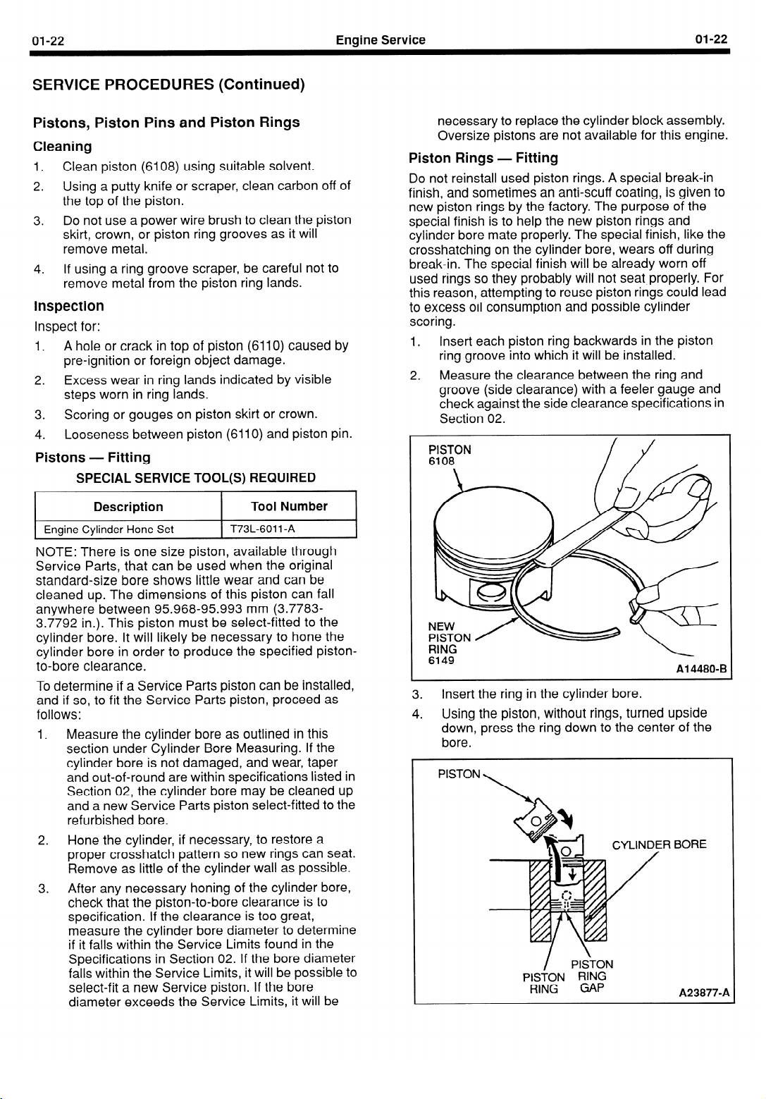
01-22
SERVICE PROCEDURES (Continued)
Engine Service
01-22
Pistons, Piston Pins and Piston Rings
Cleaning
1.
Clean piston (6108) using suitable solvent.
2. Using a putty knife or scraper, clean carbon off of
the top of the piston.
3. Do not use a power wire brush to clean the piston
skirt, crown, or piston ring grooves as it will
remove metal.
4. If using a ring groove scraper, be careful not to
remove metal from the piston ring lands.
inspection
Inspect for:
1. A hole or crack in top of piston (6110) caused by
pre-ignition or foreign object damage.
2. Excess wear in ring lands indicated by visible
steps worn in ring lands.
3. Scoring or gouges on piston skirt or crown.
4. Looseness between piston (6110) and piston pin.
Pistons
Engine Cylinder Hone Set
- Fitting
SPECIAL SERVICE TOOL(S) REQUIRED
Description
Tool Number
T73L-6011 -A
necessary to replace the cylinder block assembly.
Oversize pistons are not available for this engine.
Piston Rings - Fitting
Do not reinstall used piston rings. A special break-in
finish, and sometimes an anti-scuff coating, is given to
new piston rings by the factory. The purpose of the
special finish is to help the new piston rings and
cylinder bore mate properly. The special finish, like the
crosshatching on the cylinder bore, wears off during
break-in. The special finish will be already worn off
used rings so they probably will not seat,properly. For
this reason, attempting to reuse piston rings could lead
to excess oil consumption and possible cylinder
scoring.
Insert each piston ring backwards in the piston
1.
ring groove into which it will be installed.
2. Measure the clearance between the ring and
groove (side clearance) with a feeler gauge and
check against the side clearance specifications in
Section 02.
PISTON
6108
NOTE: There is one size piston, available through
Service Parts, that can be used when the original
standard-size bore shows little wear and can be
cleaned up. The dimensions of this piston can fall
anywhere between 95.968-95.993 mm (3.7783-
3.7792 in.). This piston must be select-fitted to the
cylinder bore. It will likely be necessary to hone the
cylinder bore in order to produce the specified pistonto-bore clearance.
To determine if a Service Parts piston can be installed,
and if so, to fit the Service Parts piston, proceed as
follows:
1. Measure the cylinder bore as outlined in this
section under Cylinder Bore Measuring. If the
cylinder bore is not damaged, and wear, taper
and out-of-round are within specifications listed in
Section 02, the cylinder bore may be cleaned up
and a new Service Parts piston select-fitted to the
refurbished bore.
2. Hone the cylinder, if necessary, to restore a
proper crosshatch pattern so new rings can seat.
Remove as little of the cylinder wall as possible.
3. After any necessary honing of the cylinder bore,
check that the piston-to-bore clearance is to
specification. If the clearance is too great,
measure the cylinder bore diameter to determine
if it falls within the Service Limits found in the
Specifications in Section 02. If the bore diameter
falls within the Service Limits, it will be possible to
select-fit a new Service piston. If the bore
diameter exceeds the Service Limits, it will be
RING
6149
Al 4480-B
3. Insert the ring in the cylinder bore.
4. Using the piston, without rings, turned upside
down, press the ring down to the center of the
bore.
PISTON
,R BORE
/ PISTON
PISTON RING
RING GAP
A23877-A
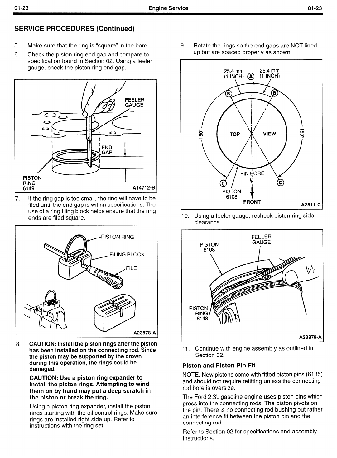
01-23
SERVICE PROCEDURES (Continued)
5.
Make sure that the ring is “square” in the bore.
6.
Check the piston ring end gap and compare to
specification found in Section 02. Using a feeler
gauge, check the piston ring end gap.
Engine Service
9.
01-23
Rotate the rings so the end gaps are NOT lined
up but are spaced properly as shown.
I
I
I
i 1
‘ISTON P
RING
6149
7.
If the ring gap is too small, the ring will have to be
filed until the end gap is within specifications. The
use of a ring filing block helps ensure that the ring
ends are filed square.
I
I
FILING BLOCK
I
i
Al 4712-B
FRONT
10. Using a feeler gauge, recheck piston ring side
clearance.
FEELER
A281 1 -C
8.
CAUTION: Install the piston rings after the piston
has been installed on the connecting rod. Since
the piston may be supported by the crown
during this operation, the rings could be
damaged.
CAUTION: Use a piston ring expander to
install the piston rings. Attempting to wind
them on by hand may put a deep scratch in
the piston or break the ring.
Using a piston ring expander, install the piston
rings starting with the oil control rings. Make sure
rings are installed right side up. Refer to
instructions with the ring set.
A238709A
A23879-A
Il. Continue with engine assembly as outlined in
Section 02.
Piston and Piston Pin Fit
NOTE: New pistons come with fitted piston pins (6135)
and should not require refitting unless the connecting
rod bore is oversize.
The Ford 2.3L gasoline engine uses piston pins which
press into the connecting rods. The piston pivots on
the pin. There is no connecting rod bushing but rather
an interference fit between the piston pin and the
connecting rod.
Refer to Section 02 for specifications and assembly
instructions.
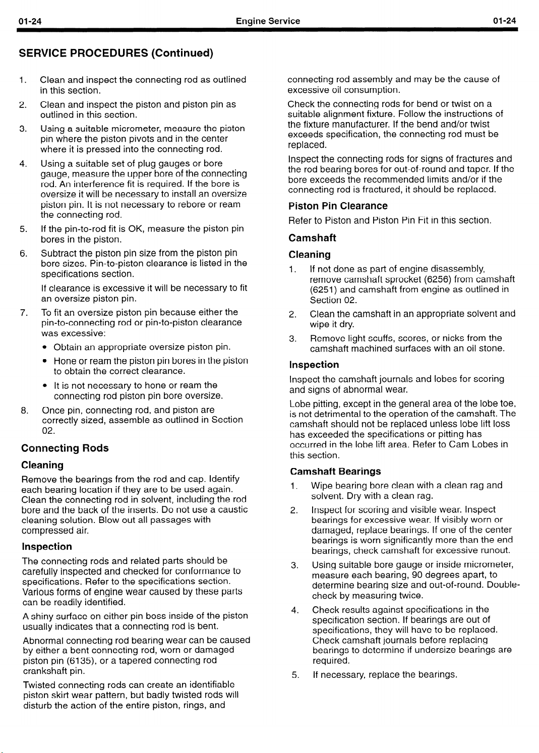
01-24
SERVICE PROCEDURES (Continued)
Engine Service
01-24
1.
Clean and inspect the connecting rod as outlined
in this section.
2.
Clean and inspect the piston and piston pin as
outlined in this section.
3.
Using a suitable micrometer, measure the piston
pin where the piston pivots and in the center
where it is pressed into the connecting rod.
4.
Using a suitable set of plug gauges or bore
gauge, measure the upper bore of the connecting
rod. An interference fit is required. If the bore is
oversize it will be necessary to install an oversize
piston pin. It is not necessary to rebore or ream
the connecting rod.
If the pin-to-rod fit is OK, measure the piston pin
5.
bores in the piston.
6.
Subtract the piston pin size from the piston pin
bore sizes. Pin-to-piston clearance is listed in the
specifications section.
If clearance is excessive it will be necessary to fit
an oversize piston pin.
7.
To fit an oversize piston pin because either the
pin-to-connecting rod or pin-to-piston clearance
was excessive:
l
Obtain an appropriate oversize piston pin.
l
Hone or ream the piston pin bores in the piston
to obtain the correct clearance.
l
It is not necessary to hone or ream the
connecting rod piston pin bore oversize.
8,
Once pin, connecting rod, and piston are
correctly sized, assemble as outlined in Section
02.
Connecting Rods
Cleaning
Remove the bearings from the rod and cap. Identify
each bearing location if they are to be used again.
Clean the connecting rod in solvent, including the rod
bore and the back of the inserts. Do not use a caustic
cleaning solution. Blow out all passages with
compressed air.
Inspection
The connecting rods and related parts should be
carefully inspected and checked for conformance to
specifications. Refer to the specifications section.
Various forms of engine wear caused by these parts
can be readily identified.
A shiny
usually indicates that a connecting
Abnormal connecting rod bearing wear can be caused
by either a bent connecting rod, worn or damaged
piston pin (6135), or a tapered connecting rod
crankshaft pin.
Twisted connecting rods can create an identifiable
piston skirt wear pattern,
disturb the action of the entire piston, rings, and
surface on either pin boss i
but
nside of the
bent.
rod is
badly twisted rods will
ston
connecting rod assembly and may be the cause of
excessive oil consumption.
Check the connecting rods for bend or twist on a
suitable alignment fixture. Follow the instructions of
the fixture manufacturer. If the bend and/or twist
exceeds specification, the connecting rod must be
replaced.
Inspect the connecting rods for signs of fractures and
the rod bearing bores for out-of-round and taper. If the
bore exceeds the recommended limits and/or if the
connecting rod is fractured, it should be replaced.
Piston Pin Clearance
Refer to Piston and Piston Pin Fit in this section.
Camshaft
Cleaning
If not done as part of engine disassembly,
1.
remove camshaft sprocket (6256) from camshaft
(6251) and camshaft from engine as outlined in
Section 02.
Clean the camshaft in an appropriate solvent and
2.
wipe it dry.
Remove light scuffs, scores, or nicks from the
3.
camshaft machined surfaces with an oil stone.
Inspection
Inspect the camshaft journals and lobes for scoring
and signs of abnormal wear.
Lobe pitting, except in the general area of the lobe toe,
is not detrimental to the operation of the camshaft. The
camshaft should not be replaced unless lobe lift loss
has exceeded the specifications or pitting has
occurred in the lobe lift area. Refer to Cam Lobes in
this section.
Camshaft Bearings
Wipe bearing bore clean with a clean rag and
1.
solvent. Dry with a clean rag.
Inspect for scoring and visible wear. Inspect
2.
bearings for excessive wear. If visibly worn or
damaged, replace bearings. If one of the center
bearings is worn significantly more than the end
bearings, check camshaft for excessive runout.
Using suitable bore gauge or inside micrometer,
3.
measure each bearing, 90 degrees apart, to
determine bearing size and out-of-round. Doublecheck by measuring twice.
Check results against specifications in the
4.
specification section. If bearings are out of
specifications, they will have to be replaced.
Check camshaft journals before replacing
bearings to determine if undersize bearings are
required.
If necessary, replace the bearings.
5,

01-25
SERVICE PROCEDURES (Continued)
Engine Service
01-25
Camshaft Bearing Journals
1.
Measure each journal twice, 90 degrees apart, to
determine journal wear, size, and out-of-round.
2. Check measurements against specifications in
the specification section.
3. If journals are excessively out-of-round or worn,
regrind to a standard undersize. Refer to Master
Parts Catalogue. If journals are too worn to be
refinished to an available undersize, replace
camshaft.
Camshaft Journals Oil Clearance
1.
Measure camshaft bearings and camshaft
bearing journals as outlined in this section.
2. Subtract size of journal from the size of its
bearing.
3.
Check clearance against specifications in
specification section.
4.
If clearance is excessive, but camshaft journals
are within specifications, simply install new
bearings. If both bearings and journals are worn,
turn camshaft journals to a standard undersize
and install new undersize bearings.
Camshaft Runout
NOTE: Check camshaft journals for out-of-round
1.
before checking for runout, or an out-of-round
condition on the center journal could be confused
for an excess runout condition. Set suitable
V-blocks on surface plate. Support outer
camshaft journals on V-blocks.
2.
Set up TOOL-4201-C, or equivalent, Dial
Indicator with Bracketry to check center bearing
journal.
Zero dial indicator.
3.
4.
Slowly rotate camshaft to determine overall
runout. If runout exceeds 0.03mm (0.0012 in.),
replace camshaft.
DIAL
n
INDICATOR
Al 4453-B
Cam Lobe Lift (Camshaft Removed)
There are two ways of measuring cam lobe lift with the
camshaft bearing (6261) removed: with a vernier
caliper camshaft bearing or on a lathe or cam grinder
with a dial indicator. The second method is more
accurate.
With Calipers
1.
Inspect camshaft bearing as outlined in this
section.
2.
Measure the distance of each cam lobe at the
major diameter.
3.
Measure the distance of each cam lobe at the
minor diameter.
4.
For each cam lobe, subtract the minor diameter
from the major diameter. The result for each lobe
is the lobe lift.
Check the lobe lift for each cam lobe against the
5.
Specifications in this section.
If any cam lobe is worn excessively, replace the
6.
camshaft and tappets.
6.35 MM 6.35 MM
li”CHff4 lN;zf
A
NO Pi-lTlNG
DIMENSION A MINUS
DIMENSION B EQUALS
THE CAM LOBE LIFT
A21 328-A
On a Camshaft Grinder or Lathe
1. Clean and inspect the camshaft as outlined in this
section.
2.
Install the camshaft on the lathe or camshaft
grinder centers.
3.
Position the machine’s dial indicator at the heel of
the cam lobe you are going to check.
4.
Zero the dial indicator.
5.
Slowly turn the camshaft until the point of the dial
indicator is on the tip of the cam lobe.
6.
Read the dial indicator. This is your cam lobe lift.
7.
Check the lobe lift against the specifications in
the specifications section. If any cam is
excessively worn, replace the camshaft and
tappets.
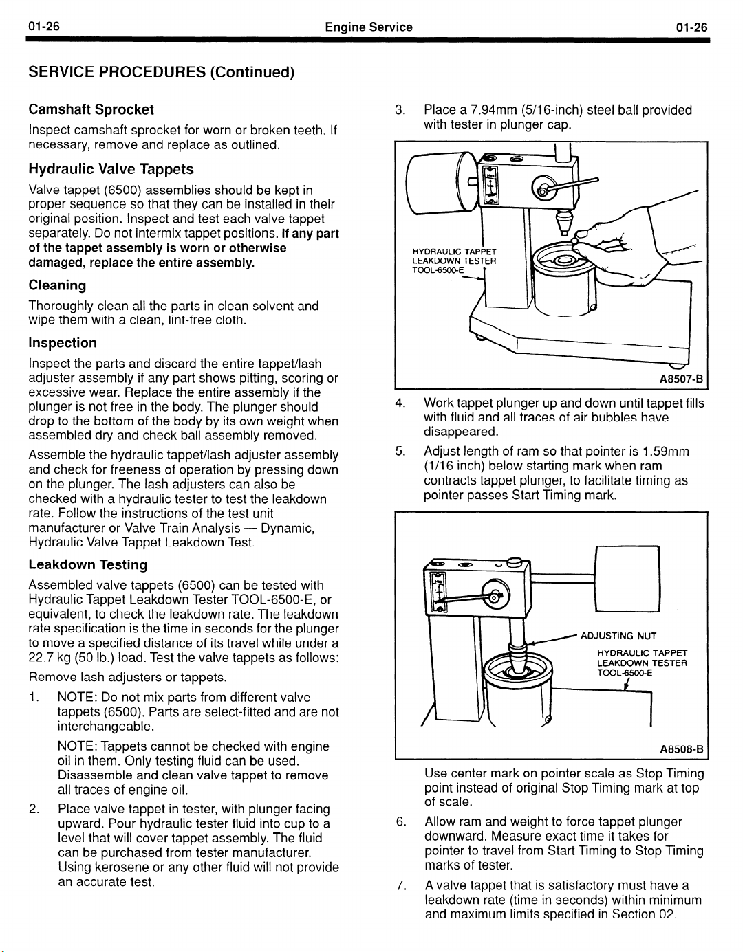
01-26
Engine Service
SERVICE PROCEDURES (Continued)
Camshaft Sprocket
Inspect camshaft sprocket for worn or broken teeth. If
necessary, remove and replace as outlined.
Hydraulic Valve Tappets
Valve tappet (6500) assemblies should be kept in
proper sequence so that they can be installed in their
original position. Inspect and test each valve tappet
separately. Do not intermix tappet positions.
of the tappet assembly is worn or otherwise
damaged, replace the entire assembly.
If any part
Cleaning
Thoroughly clean all the parts in clean solvent and
wipe them with a clean, lint-free cloth.
Inspection
Inspect the parts and discard the entire tappet/lash
adjuster assembly if any part shows pitting, scoring or
excessive wear. Replace the entire assembly if the
plunger is not free in the body. The plunger should
drop to the bottom of the body by its own weight when
assembled dry and check ball assembly removed.
Assemble the hydraulic tappet/lash adjuster assembly
and check for freeness of operation by pressing down
on the plunger. The lash adjusters can also be
checked with a hydraulic tester to test the leakdown
rate. Follow the instructions of the test unit
manufacturer or Valve Train Analysis - Dynamic,
Hydraulic Valve Tappet Leakdown Test.
Leakdown Testing
Assembled valve tappets (6500) can be tested with
Hydraulic Tappet Leakdown Tester TOOL-6500-E, or
equivalent, to check the leakdown rate. The leakdown
rate specification is the time in seconds for the plunger
to move a specified distance of its travel while under a
22.7 kg (50 lb.) load. Test the valve tappets as follows:
Remove lash adjusters or tappets.
1. NOTE: Do not mix parts from different valve
tappets (6500). Parts are select-fitted and are not
interchangeable.
NOTE: Tappets cannot be checked with engine
oil in them. Only testing fluid can be used.
Disassemble and clean valve tappet to remove
all traces of engine oil.
2. Place valve tappet in tester, with plunger facing
upward. Pour hydraulic tester fluid into cup to a
level that will cover tappet assembly. The fluid
can be purchased from tester manufacturer.
Using kerosene or any other fluid will not provide
an accurate test.
01-26
Place a 7.94mm (5/l 6-inch) steel ball provided
3.
with tester in plunger cap.
A
A8507-B
4. Work tappet plunger up and down until tappet fills
with fluid and all traces of air bubbles have
disappeared.
Adjust length of ram so that pointer is 1.59mm
5.
(l/l 6 inch) below starting mark when ram
contracts tappet plunger, to facilitate timing as
pointer passes Start Timing mark.
ADJUSTING NUT
HYDRAULIC TAPPET
A8508-B
Use center mark on pointer scale as Stop Timing
point instead of original Stop Timing mark at top
of scale.
6. Allow ram and weight to force tappet plunger
downward. Measure exact time it takes for
pointer to travel from Start Timing to Stop Timing
marks of tester.
7. A valve tappet that is satisfactory must have a
leakdown rate (time in seconds) within minimum
and maximum limits specified in Section 02.
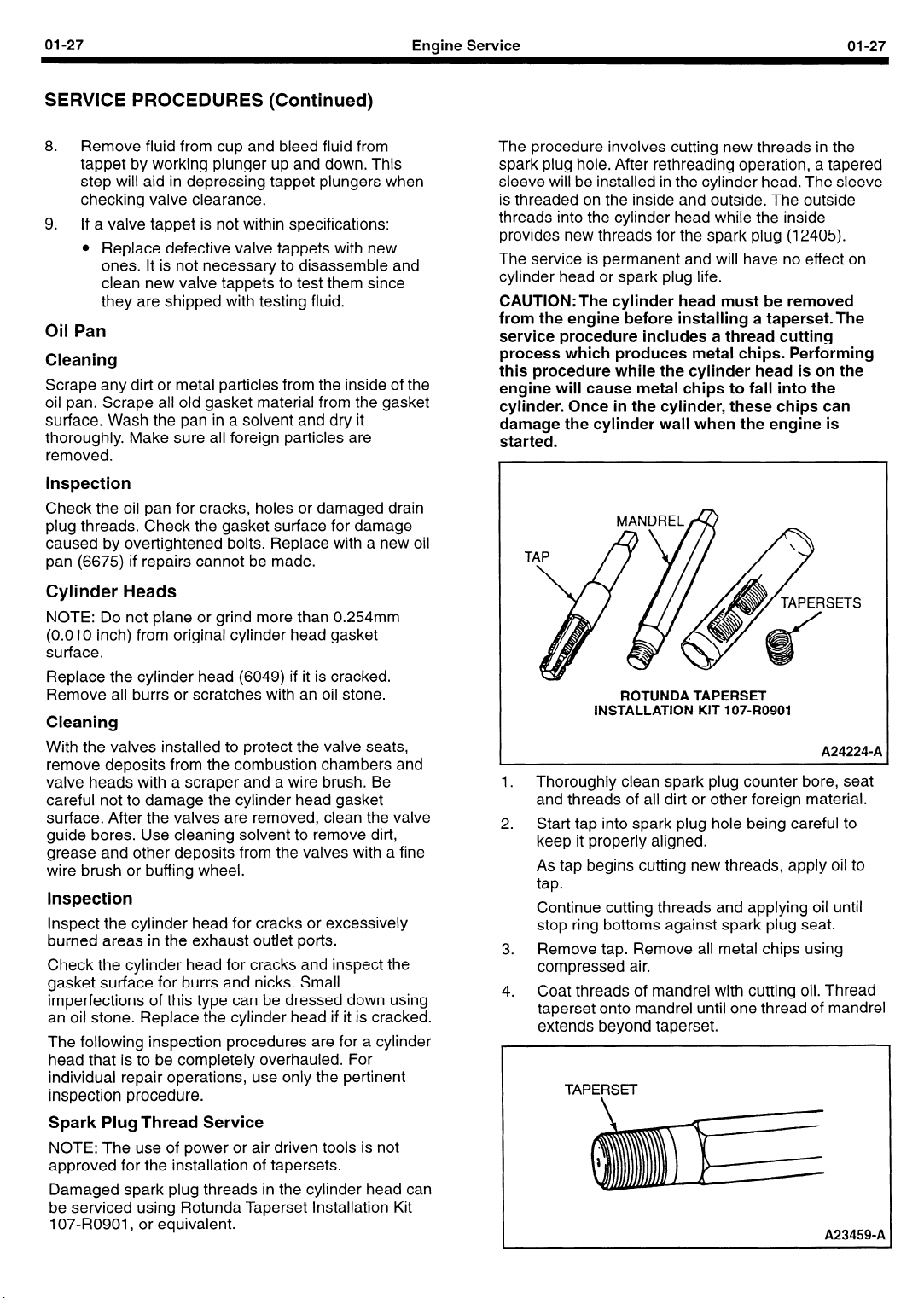
01-27
Engine Service
SERVICE PROCEDURES (Continued)
8.
Remove fluid from cup and bleed fluid from
tappet by working plunger up and down. This
step will aid in depressing tappet plungers when
checking valve clearance.
9.
If a valve tappet is not within specifications:
l
Replace defective valve tappets with new
ones. It is not necessary to disassemble and
clean new valve tappets to test them since
they are shipped with testing fluid.
Oil Pan
Cleaning
Scrape any dirt or metal particles from the inside of the
oil pan. Scrape all old gasket material from the gasket
surface. Wash the pan in a solvent and dry it
thoroughly. Make sure all foreign particles are
removed.
Inspection
Check the oil pan for cracks, holes or damaged drain
plug threads. Check the gasket surface for damage
caused by over-tightened bolts. Replace with a new oil
pan (6675) if repairs cannot be made.
01-27
The procedure involves cutting new threads in the
spark plug hole. After rethreading operation, a tapered
sleeve will be installed in the cylinder head. The sleeve
is threaded on the inside and outside. The outside
threads into the cylinder head while the inside
provides new threads for the spark plug
The service is permanent and will have no effect on
cylinder head or spark plug life.
CAUTION:The
cylinder head must be removed
(12405).
from the engine before installing a taperset.The
service procedure includes a thread cutting
process which produces metal chips. Performing
this procedure while the cylinder head is on the
engine will cause metal chips to fall into the
cylinder. Once in the cylinder, these chips can
damage the cylinder wall when the engine is
started.
Cylinder Heads
NOTE: Do not plane or grind more than 0.254mm
(0.010 inch) from original cylinder head gasket
surface.
Replace the cylinder head (6049) if it is cracked.
Remove all burrs or scratches with an oil stone.
Cleaning
With the valves installed to protect the valve seats,
remove deposits from the combustion chambers and
valve heads with a scraper and a wire brush. Be
careful not to damage the cylinder head gasket
surface. After the valves are removed, clean the valve
guide bores. Use cleaning solvent to remove dirt,
grease and other deposits from the valves with a fine
wire brush or buffing wheel.
Inspection
Inspect the cylinder head for cracks or excessively
burned areas in the exhaust outlet ports.
Check the cylinder head for cracks and inspect the
gasket surface for burrs and nicks. Small
imperfections of this type can be dressed down using
an oil stone. Replace the cylinder head if it is cracked.
The following inspection procedures are for a cylinder
head that is to be completely overhauled. For
individual repair operations, use only the pertinent
inspection procedure.
Spark Plug Thread Service
NOTE: The use of power or air driven tools is not
approved for the installation of tapersets.
Damaged spark plug threads in the cylinder head can
be serviced using Rotunda Taperset Installation Kit
107-R0901,
or equivalent.
ROTUNDA TAPERSET
INSTALLATION KIT 107-R0901
I.
Thoroughly clean spark plug counter bore, seat
and threads of all dirt or other foreign material.
2.
Start tap into spark plug hole being careful to
keep it properly aligned.
As tap begins cutting new threads, apply oil to
tap.
Continue cutting threads and applying oil until
stop ring bottoms against spark plug seat.
3.
Remove tap. Remove all metal chips using
compressed air.
4.
Coat threads of mandrel with cutting oil. Thread
taperset onto mandrel until one thread of mandrel
extends beyond taperset.
TAPERSET
SETS
A24224-A
A23459-A
 Loading...