

Page 1
fordowner.com ford.ca
2015 ESCAPE Owner’s Manual
2015 ESCAPE Owner’s Manual
July 2014
First Printing
Owner’s Manual
Escape
Litho in U.S.A.
FJ5J 19A321 AA
Page 2

The information contained in this publication was correct at the time of going to print. In the interest of
continuous development, we reserve the right to change specifications, design or equipment at any time
without notice or obligation. No part of this publication may be reproduced, transmitted, stored in a
retrieval system or translated into any language in any form by any means without our written permission.
Errors and omissions excepted.
© Ford Motor Company 2014
All rights reserved.
Part Number: 20140703210941
Page 3

Page 4

Introduction
About This Manual...........................................7
Symbols Glossary.............................................7
Data Recording..................................................9
California Proposition 65..............................11
Perchlorate.........................................................11
Ford Credit..........................................................11
Replacement Parts
Recommendation........................................11
Special Notices................................................12
Mobile Communications
Equipment.....................................................12
Export Unique Options..................................13
At a Glance
At a Glance........................................................14
Child Safety
General Information.......................................19
Installing Child Seats....................................20
Booster Seats..................................................26
Child Seat Positioning..................................28
Child Safety Locks.........................................29
Safety Belts
Principle of Operation....................................31
Fastening the Safety Belts..........................32
Safety Belt Height Adjustment.................35
Safety Belt Warning Lamp and Indicator
Chime.............................................................35
Safety Belt Minder.........................................36
Child Restraint and Safety Belt
Maintenance................................................37
Personal Safety System™
Personal Safety System™..........................38
Supplementary Restraints
System
Principle of Operation..................................39
Driver and Passenger Airbags...................40
Front Passenger Sensing System.............41
Side Airbags.....................................................43
Driver Knee Airbag.........................................44
Safety Canopy™............................................44
Crash Sensors and Airbag Indicator.......46
Airbag Disposal...............................................47
Keys and Remote Controls
Principle of Operation..................................48
General Information on Radio
Frequencies.................................................48
Remote Control..............................................49
Replacing a Lost Key or Remote
Control............................................................52
MyKey™
Principle of Operation..................................53
Creating a MyKey............................................53
Clearing All MyKeys.......................................54
Checking MyKey System Status...............55
Using MyKey With Remote Start
Systems.........................................................56
MyKey Troubleshooting...............................56
Locks
Locking and Unlocking.................................58
Manual Liftgate...............................................62
Power Liftgate.................................................63
Keyless Entry...................................................65
Security
Passive Anti-Theft System.........................67
Anti-Theft Alarm...........................................68
Steering Wheel
Adjusting the Steering Wheel...................69
Audio Control..................................................69
Voice Control...................................................70
Cruise Control..................................................70
1
Escape (TM2), enUSA, First Printing
Table of Contents
Page 5

Information Display Control.......................70
Wipers and Washers
Windshield Wipers..........................................71
Autowipers.........................................................71
Windshield Washers......................................72
Rear Window Wiper and Washers...........73
Lighting
Lighting Control...............................................74
Autolamps........................................................74
Instrument Lighting Dimmer......................75
Headlamp Exit Delay....................................76
Daytime Running Lamps.............................76
Front Fog Lamps.............................................77
Direction Indicators........................................77
Interior Lamps..................................................77
Ambient Lighting.............................................77
Windows and Mirrors
Power Windows..............................................79
Global Opening..............................................80
Exterior Mirrors...............................................80
Interior Mirror...................................................82
Sun Visors.........................................................82
Moonroof...........................................................83
Instrument Cluster
Gauges...............................................................84
Warning Lamps and Indicators................86
Audible Warnings and Indicators.............88
Information Displays
General Information.....................................90
Trip Computer.................................................92
Information Messages.................................93
Climate Control
Manual Climate Control............................103
Automatic Climate Control......................104
Hints on Controlling the Interior
Climate........................................................106
Heated Windows and Mirrors..................109
Cabin Air Filter...............................................109
Remote Start.................................................109
Seats
Sitting in the Correct Position....................111
Head Restraints...............................................111
Manual Seats..................................................113
Power Seats.....................................................114
Memory Function...........................................115
Rear Seats........................................................116
Heated Seats...................................................117
Rear Seat Armrest.........................................117
Universal Garage Door
Opener
Universal Garage Door Opener................118
Auxiliary Power Points
Auxiliary Power Points................................122
Storage Compartments
Center Console..............................................124
Overhead Console........................................124
Starting and Stopping the
Engine
General Information....................................125
Ignition Switch...............................................125
Keyless Starting.............................................125
Starting a Gasoline Engine.......................126
Engine Block Heater....................................129
Fuel and Refueling
Safety Precautions........................................131
Fuel Quality.....................................................132
Running Out of Fuel.....................................132
2
Escape (TM2), enUSA, First Printing
Table of Contents
Page 6

Refueling..........................................................134
Fuel Consumption........................................135
Emission Control System..........................136
Transmission
Automatic Transmission............................139
Four-Wheel Drive
Principle of Operation.................................142
Using Four-Wheel Drive.............................142
Brakes
General Information....................................147
Hints on Driving With Anti-Lock
Brakes...........................................................147
Parking Brake.................................................148
Hill Start Assist..............................................148
Traction Control
Principle of Operation................................149
Using Traction Control...............................149
Stability Control
Principle of Operation................................150
Using Stability Control.................................151
Parking Aids
Parking Aid......................................................152
Active Park Assist.........................................154
Rear View Camera.......................................158
Cruise Control
Principle of Operation..................................161
Using Cruise Control.....................................161
Driving Aids
Blind Spot Information System..............162
Eco Mode........................................................166
Steering............................................................166
Load Carrying
Rear Under Floor Storage.........................168
Luggage Covers.............................................168
Roof Racks and Load Carriers.................169
Load Limit........................................................170
Towing
Towing a Trailer..............................................178
Trailer Sway Control.....................................179
Recommended Towing Weights.............179
Essential Towing Checks............................181
Towing Points................................................183
Transporting the Vehicle...........................184
Towing the Vehicle on Four Wheels......185
Driving Hints
Breaking-In.....................................................186
Economical Driving......................................186
Driving Through Water................................187
Floor Mats........................................................187
Roadside Emergencies
Roadside Assistance..................................189
Hazard Warning Flashers..........................190
Fuel Shutoff...................................................190
Jump Starting the Vehicle..........................191
Post-Crash Alert System...........................193
Customer Assistance
Getting the Services You Need...............194
In California (U.S. Only).............................195
The Better Business Bureau (BBB) Auto
Line Program (U.S. Only)......................196
Utilizing the Mediation/Arbitration
Program (Canada Only)........................196
Getting Assistance Outside the U.S. and
Canada.........................................................197
Ordering Additional Owner's
Literature.....................................................198
3
Escape (TM2), enUSA, First Printing
Table of Contents
Page 7

Reporting Safety Defects (U.S.
Only).............................................................198
Reporting Safety Defects (Canada
Only).............................................................199
Fuses
Fuse Specification Chart..........................200
Changing a Fuse..........................................209
Maintenance
General Information....................................210
Opening and Closing the Hood...............210
Under Hood Overview - 1.6L
EcoBoost™.................................................212
Under Hood Overview - 2.0L
EcoBoost™.................................................213
Under Hood Overview - 2.5L....................214
Engine Oil Dipstick - 2.0L EcoBoost™/
2.5L.................................................................215
Engine Oil Dipstick - 1.6L
EcoBoost™.................................................215
Engine Oil Check...........................................215
Engine Coolant Check................................216
Automatic Transmission Fluid
Check............................................................219
Brake Fluid Check.........................................219
Power Steering Fluid Check......................219
Washer Fluid Check.....................................219
Fuel Filter.........................................................219
Changing the 12V Battery.........................220
Checking the Wiper Blades.......................221
Changing the Wiper Blades......................221
Adjusting the Headlamps.........................222
Removing a Headlamp..............................224
Changing a Bulb...........................................224
Bulb Specification Chart...........................228
Changing the Engine Air Filter.................229
Vehicle Care
General Information....................................231
Cleaning Products........................................231
Cleaning the Exterior...................................231
Waxing.............................................................232
Cleaning the Engine....................................232
Cleaning the Windows and Wiper
Blades..........................................................233
Cleaning the Interior...................................233
Cleaning the Instrument Panel and
Instrument Cluster Lens........................233
Cleaning Leather Seats.............................234
Repairing Minor Paint Damage...............235
Cleaning the Alloy Wheels.......................235
Vehicle Storage.............................................235
Wheels and Tires
General Information...................................238
Tire Care..........................................................240
Using Snow Chains.....................................254
Tire Pressure Monitoring System...........255
Changing a Road Wheel...........................258
Technical Specifications...........................262
Capacities and Specific-
ations
Engine Specifications................................264
Motorcraft Parts...........................................265
Vehicle Identification Number................265
Vehicle Certification Label.......................266
Transmission Code Designation............267
Technical Specifications..........................268
Audio System
General Information....................................272
Audio Unit - Vehicles With: AM/FM/
CD..................................................................273
Audio Unit - Vehicles With: AM/FM/CD/
SYNC............................................................275
Audio Unit - Vehicles With: AM/FM/CD/
SYNC/Satellite Radio.............................277
Audio Unit - Vehicles With: Premium AM/
FM/CD..........................................................279
4
Escape (TM2), enUSA, First Printing
Table of Contents
Page 8

Audio Unit - Vehicles With: Sony AM/FM/
CD...................................................................281
Digital Radio..................................................284
Satellite Radio..............................................286
Audio Input Jack..........................................289
USB Port.........................................................289
Media Hub......................................................290
SYNC™
General Information....................................291
Using Voice Recognition...........................293
Using SYNC™ With Your Phone............295
SYNC™ Applications and Services......306
Using SYNC™ With Your Media
Player............................................................313
SYNC™ Troubleshooting...........................321
MyFord Touch™
General Information...................................330
Settings............................................................337
Entertainment...............................................347
Phone...............................................................364
Information....................................................370
Climate............................................................379
Navigation......................................................382
MyFord Touch™ Troubleshooting........390
Accessories
Accessories....................................................396
Appendices
End User License Agreement.................398
Extended Service Plan
(ESP)
Extended Service Plan (ESP)..................418
Scheduled Maintenance
General Maintenance Information.......420
Normal Scheduled Maintenance..........423
Special Operating Conditions Scheduled
Maintenance.............................................426
Scheduled Maintenance Record...........429
5
Escape (TM2), enUSA, First Printing
Table of Contents
Page 9

6
Escape (TM2), enUSA, First Printing
Page 10
ABOUT THIS MANUAL
Thank you for choosing Ford. We
recommend that you take some time to
get to know your vehicle by reading this
manual. The more that you know about
it, the greater the safety and pleasure you
will get from driving it.
WARNING
Driving while distracted can result in
loss of vehicle control, crash and
injury. We strongly recommend that
you use extreme caution when using any
device that may take your focus off the
road. Your primary responsibility is the safe
operation of your vehicle. We recommend
against the use of any hand-held device
while driving and encourage the use of
voice-operated systems when possible.
Make sure you are aware of all applicable
local laws that may affect the use of
electronic devices while driving.
Note: This manual describes product
features and options available throughout
the range of available models, sometimes
even before they are generally available. It
may describe options not fitted to the
vehicle you have purchased.
Note: Some of the illustrations in this
manual may show features as used in
different models, so may appear different
to you on your vehicle.
Note: Always use and operate your vehicle
in line with all applicable laws and
regulations.
Note: Pass on this manual when selling
your vehicle. It is an integral part of your
vehicle.
This manual may qualify the location of a
component as left-hand side or right-hand
side. The side is determined when facing
forward in the seat.
E154903
Right-hand side.A
Left-hand side.B
SYMBOLS GLOSSARY
These are some of the symbols you may
see on your vehicle.
Safety alert
See Owner's Manual
Air conditioning system
Anti-lock braking system
Avoid smoking, flames or sparks
Battery
Battery acid
Brake fluid - non petroleum
based
7
Escape (TM2), enUSA, First Printing
Introduction
Page 11
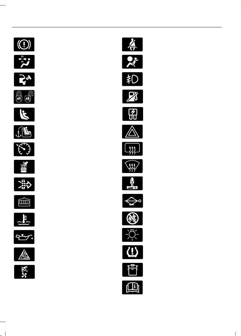
Brake system
Cabin air filter
Check fuel cap
Child safety door lock or unlock
Child seat lower anchor
Child seat tether anchor
E71340
Cruise control
Do not open when hot
Engine air filter
Engine coolant
Engine coolant temperature
Engine oil
Explosive gas
Fan warning
Fasten safety belt
Front airbag
Front fog lamps
Fuel pump reset
Fuse compartment
Hazard warning flashers
Heated rear window
Heated windshield
Interior luggage compartment
release
Jack
Keep out of reach of children
Lighting control
Low tire pressure warning
Maintain correct fluid level
Note operating instructions
8
Escape (TM2), enUSA, First Printing
Introduction
Page 12
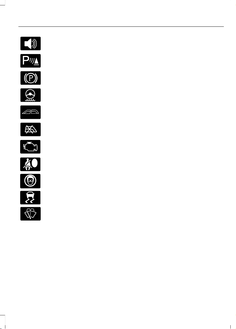
Panic alarm
E139213
Parking aid
Parking brake
Power steering fluid
Power windows front/rear
Power window lockout
Service engine soon
Side airbag
Shield the eyes
E138639
Stability control
Windshield wash and wipe
DATA RECORDING
Service Data Recording
Service data recorders in your vehicle are
capable of collecting and storing
diagnostic information about your vehicle.
This potentially includes information about
the performance or status of various
systems and modules in the vehicle, such
as engine, throttle, steering or brake
systems. In order to properly diagnose and
service your vehicle, Ford Motor Company,
Ford of Canada, and service and repair
facilities may access or share among them
vehicle diagnostic information received
through a direct connection to your vehicle
when diagnosing or servicing your vehicle.
Additionally, when your vehicle is in for
service or repair, Ford Motor Company,
Ford of Canada, and service and repair
facilities may access or share among them
data for vehicle improvement purposes.
For U.S. only (if equipped), if you choose
to use the SYNC Vehicle Health Report,
you consent that certain diagnostic
information may also be accessed
electronically by Ford Motor Company and
Ford authorized service facilities, and that
the diagnostic information may be used
for any purpose. See SYNC™ (page 291).
Event Data Recording
This vehicle is equipped with an event
data recorder. The main purpose of an
event data recorder is to record, in
certain crash or near crash-like
situations, such as an airbag
deployment or hitting a road obstacle;
this data will assist in understanding
how a vehicle’s systems performed.
The event data recorder is designed to
record data related to vehicle dynamics
and safety systems for a short period
of time, typically 30 seconds or less.
The event data recorder in this vehicle
is designed to record such data as:
• How various systems in your vehicle
were operating;
• Whether or not the driver and
passenger safety belts were
buckled/fastened;
• How far (if at all) the driver was
depressing the accelerator and/or
the brake pedal; and
9
Escape (TM2), enUSA, First Printing
Introduction
Page 13

• How fast the vehicle was traveling;
and
• Where the driver was positioning
the steering wheel.
This data can help provide a better
understanding of the circumstances in
which crashes and injuries occur.
Note: Event data recorder data is
recorded by your vehicle only if a
non-trivial crash situation occurs; no data
is recorded by the event data recorder
under normal driving conditions and no
personal data or information (e.g., name,
gender, age, and crash location) is
recorded (see limitations regarding 911
Assist and Traffic, directions and
Information privacy below). However,
parties, such as law enforcement, could
combine the event data recorder data
with the type of personally identifying
data routinely acquired during a crash
investigation.
To read data recorded by an event data
recorder, special equipment is required,
and access to the vehicle or the event
data recorder is needed. In addition to
the vehicle manufacturer, other
parties, such as law enforcement, that
have such special equipment, can read
the information if they have access to
the vehicle or the event data recorder.
Ford Motor Company and Ford of
Canada do not access event data
recorder information without obtaining
consent, unless pursuant to court order
or where required by law enforcement,
other government authorities or other
third parties acting with lawful
authority. Other parties may seek to
access the information independently
of Ford Motor Company and Ford of
Canada.
Note: Including to the extent that any
law pertaining to Event Data Recorders
applies to SYNC or its features, please
note the following: Once 911 Assist (if
equipped) is enabled (set ON), 911 Assist
may, through any paired and connected
cell phone, disclose to emergency
services that the vehicle has been in a
crash involving the deployment of an
airbag or, in certain vehicles, the
activation of the fuel pump shut-off.
Certain versions or updates to 911 Assist
may also be capable of being used to
electronically or verbally provide to 911
operators the vehicle location (such as
latitude and longitude), and/or other
details about the vehicle or crash or
personal information about the
occupants to assist 911 operators to
provide the most appropriate emergency
services. If you do not want to disclose
this information, do not activate the 911
Assist feature. See SYNC™ (page 291).
Additionally, when you connect to
Traffic, Directions and Information (if
equipped, U.S. only), the service uses
GPS technology and advanced vehicle
sensors to collect the vehicle’s current
location, travel direction, and speed
(“vehicle travel information”), only to
help provide you with the directions,
traffic reports, or business searches
that you request. If you do not want
Ford or its vendors to receive this
information, do not activate the
service. For more information, see
Traffic, Directions and Information,
Terms and Conditions. See SYNC™
(page 291).
10
Escape (TM2), enUSA, First Printing
Introduction
Page 14

CALIFORNIA PROPOSITION 65
WARNING
Some constituents of engine
exhaust, certain vehicle components,
certain fluids contained in vehicles
and certain products of component wear
contain or emit chemicals known to the
State of California to cause cancer and
birth defects or other reproductive harm.
PERCHLORATE
Certain components in your vehicle such
as airbag modules, safety belt
pretensioners and remote control batteries
may contain perchlorate material. Special
handling may apply for service or vehicle
end of life disposal. For more information
visit:
Web Address
www.dtsc.ca.gov/hazardouswaste/
perchlorate
FORD CREDIT
(U.S. Only)
Ford Credit offers a full range of financing
and lease plans to help you acquire your
vehicle. If you have financed or leased your
vehicle through Ford Credit, thank you for
your business.
For your convenience we offer a number
of ways to contact us, as well as to help
manage your account.
Phone: 1-800-727-7000
For more information regarding Ford Credit,
as well as to access Account Manager,
please go to www.fordcredit.com.
REPLACEMENT PARTS RECOMMENDATION
Your vehicle has been built to the highest
standards using quality parts. We
recommend that you demand the use of
genuine Ford and Motorcraft parts
whenever your vehicle requires scheduled
maintenance or repair. You can clearly
identify genuine Ford and Motorcraft parts
by looking for the Ford, FoMoCo or
Motorcraft branding on the parts or their
packaging.
Scheduled Maintenance and
Mechanical Repairs
One of the best ways for you to make sure
that your vehicle provides years of service
is to have it maintained in line with our
recommendations using parts that
conform to the specifications detailed in
this Owner’s Manual. Genuine Ford and
Motorcraft parts meet or exceed these
specifications.
Collision Repairs
We hope that you never experience a
collision, but accidents do happen. Genuine
Ford replacement collision parts meet our
stringent requirements for fit, finish,
structural integrity, corrosion protection
and dent resistance. During vehicle
development we validate these parts
deliver the intended level of protection as
a whole system. A great way to know for
sure you are getting this level of protection
is to use genuine Ford replacement
collision parts.
11
Escape (TM2), enUSA, First Printing
Introduction
Page 15

Warranty on Replacement Parts
Genuine Ford and Motorcraft replacement
parts are the only replacement parts that
benefit from a Ford Warranty. Damage
caused to your vehicle as a result of the
failure of non-Ford parts may not be
covered by the Ford Warranty. For
additional information, refer to the terms
and conditions of the Ford Warranty.
SPECIAL NOTICES
New Vehicle Limited Warranty
For a detailed description of what is
covered and what is not covered by your
vehicle’s New Vehicle Limited Warranty,
refer to the Warranty Manual that is
provided to you along with your Owner’s
Manual.
Special Instructions
For your added safety, your vehicle is fitted
with sophisticated electronic controls.
WARNINGS
Failure to follow the specific
warnings and instructions could
result in personal injury. See
Supplementary Restraints System
(page 39).
Front seat mounted rear-facing child
or infant seats should NEVER be
placed in front of an active
passenger airbag.
Notice to Owners of Pickup Trucks
and Utility Type Vehicles
WARNING
Utility vehicles have a significantly
higher rollover rate than other types
of vehicles.
Before you drive your vehicle, please read
this Owner’s Guide carefully. Your vehicle
is not a passenger car. As with other
vehicles of this type, failure to operate this
vehicle correctly may result in loss of
vehicle control, vehicle rollover, personal
injury or death.
Using Your Vehicle With a
Snowplow
Do not use this vehicle for
snowplowing.
Your vehicle is not equipped with a
snowplowing package.
Using Your Vehicle as an
Ambulance
Do not use this vehicle as an
ambulance.
Your vehicle is not equipped with the Ford
Ambulance Preparation Package.
MOBILE COMMUNICATIONS EQUIPMENT
Using mobile communications equipment
is becoming increasingly important in the
conduct of business and personal affairs.
However, you must not compromise your
own or others’ safety when using such
equipment. Mobile communications can
enhance personal safety and security when
appropriately used, particularly in
emergency situations. Safety must be
paramount when using mobile
communications equipment to avoid
negating these benefits. Mobile
communication equipment includes, but
is not limited to, cellular phones, pagers,
portable email devices, text messaging
devices and portable two-way radios.
12
Escape (TM2), enUSA, First Printing
Introduction
Page 16

WARNING
Driving while distracted can result in
loss of vehicle control, crash and
injury. We strongly recommend that
you use extreme caution when using any
device that may take your focus off the
road. Your primary responsibility is the safe
operation of your vehicle. We recommend
against the use of any hand-held device
while driving and encourage the use of
voice-operated systems when possible.
Make sure you are aware of all applicable
local laws that may affect the use of
electronic devices while driving.
EXPORT UNIQUE OPTIONS
For your particular global region, your
vehicle may be equipped with features and
options that are different from the features
and options that are described in this
Owner’s Manual. A market unique
supplement may be supplied that
complements this book. By referring to the
market unique supplement, if provided,
you can properly identify those features,
recommendations and specifications that
are unique to your vehicle. This Owner’s
Manual is written primarily for the U.S. and
Canadian Markets. Features or equipment
listed as standard may be different on units
built for Export. Refer to this Owner’s
Manual for all other required
information and warnings.
13
Escape (TM2), enUSA, First Printing
Introduction
Page 17
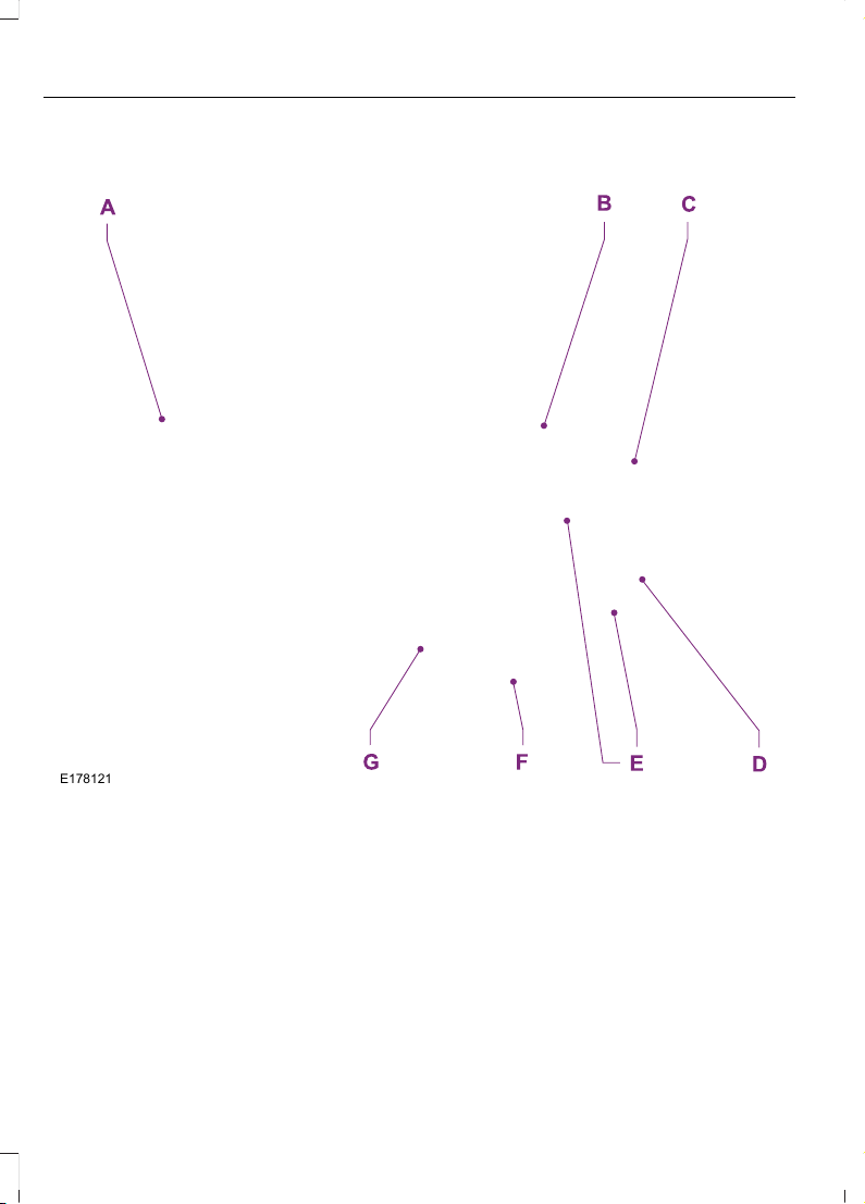
Front Exterior Overview
E178121
See Locking and Unlocking (page 58). See Keyless Entry (page 65).A
See Changing the Wiper Blades (page 221).B
See Maintenance (page 210).C
See Towing Points (page 183).D
See Changing a Bulb (page 224).E
Tire pressures. See Tire Pressure Monitoring System (page 255).F
See Changing a Road Wheel (page 258).G
14
Escape (TM2), enUSA, First Printing
At a Glance
Page 18
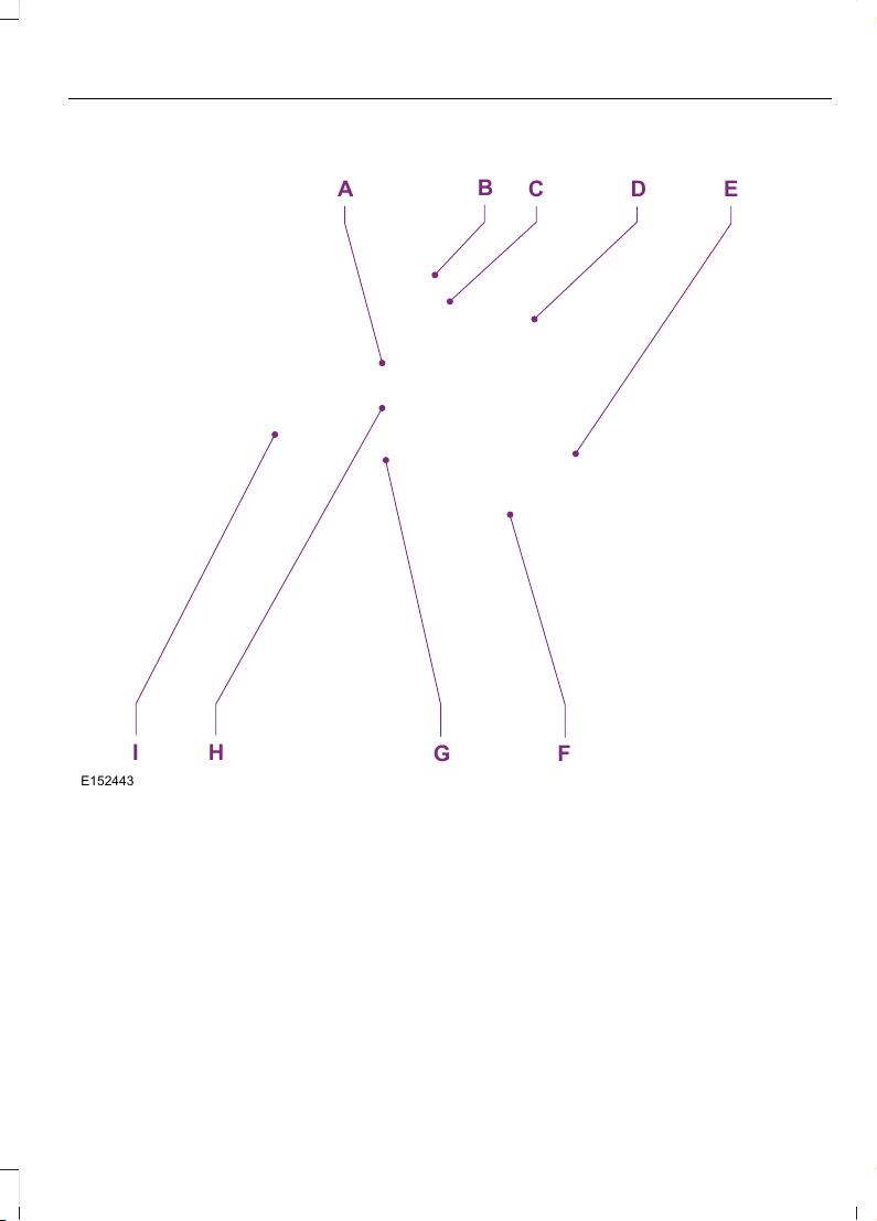
Vehicle Interior Overview
E152443
F
A E
B
C
D
HI
G
See Transmission (page 139).A
See Locking and Unlocking (page 58).B
See Power Windows (page 79). See Exterior Mirrors (page 80).C
See Head Restraints (page 111).D
See Fastening the Safety Belts (page 32).E
See Rear Seats (page 116).F
See Manual Seats (page 113). See Power Seats (page 114).G
See Parking Brake (page 148).H
See Opening and Closing the Hood (page 210).I
15
Escape (TM2), enUSA, First Printing
At a Glance
Page 19
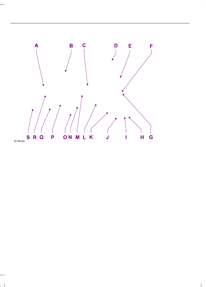
Instrument Panel Overview
E178122
Direction indicators. See Direction Indicators (page 77). High beam. See
Lighting Control (page 74).
A
Instrument cluster. See Gauges (page 84). See Warning Lamps and
Indicators (page 86).
B
Wiper lever. See Wipers and Washers (page 71).C
Information and entertainment display.D
Audio unit. See Audio System (page 272).E
Door lock indicator. See Locking and Unlocking (page 58).F
Hazard warning flasher switch. See Hazard Warning Flashers (page 190).G
Parking aid switch. See Parking Aids (page 152).H
Active park assist switch. See Active Park Assist (page 154).I
Heated rear window switch. See Heated Windows and Mirrors (page 109).J
Climate controls. See Climate Control (page 103).K
Start button. See Keyless Starting (page 125).L
Audio control. See Audio Control (page 69). Telephone control. See Using
SYNC™ With Your Phone (page 295).
M
16
Escape (TM2), enUSA, First Printing
At a Glance
Page 20
Ignition switch. See Ignition Switch (page 125).N
Steering wheel adjustment. See Adjusting the Steering Wheel (page 69).O
Horn.P
Cruise control switches. See Using Cruise Control (page 161).Q
Information display controls. See Information Displays (page 90).R
Lighting control. See Lighting Control (page 74). Fog lamps. See Front Fog
Lamps (page 77). Instrument lighting dimmer. See Manual Climate Control
(page 103).
S
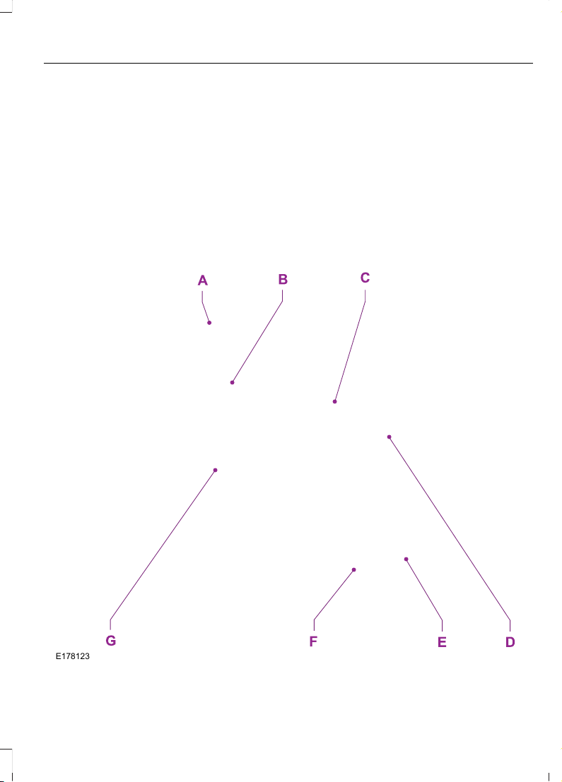
Rear Exterior Overview
E178123
17
Escape (TM2), enUSA, First Printing
At a Glance
Page 21

See Changing a Bulb (page 224).A
See Checking the Wiper Blades (page 221).B
See Changing a Bulb (page 224).C
See Refueling (page 134).D
See Changing a Road Wheel (page 258).E
Tire pressures. See Tire Care (page 240).F
Spare wheel, jack and lug wrench. See Changing a Road Wheel (page 258).
Fuel funnel. See Running Out of Fuel (page 132).
G
18
Escape (TM2), enUSA, First Printing
At a Glance
Page 22

GENERAL INFORMATION
See the following sections for directions
on how to properly use safety restraints
for children.
WARNINGS
Always make sure your child is
secured properly in a device that is
appropriate for their height, age and
weight. Child safety restraints must be
bought separately from your vehicle.
Failure to follow these instructions and
guidelines may result in an increased risk
of serious injury or death to your child.
All children are shaped differently.
The recommendations for safety
restraints are based on probable
child height, age and weight thresholds
from National Highway Traffic Safety
Administration and other safety
organizations, or are the minimum
WARNINGS
requirements of law. Ford recommends
checking with a NHTSA Certified Child
Passenger Safety Technician (CPST) and
consult your pediatrician to make sure your
child seat is appropriate for your child, and
is compatible with and properly installed
in your vehicle. To locate a child seat fitting
station and CPST, contact the NHTSA toll
free at 1-888-327-4236 or go to
http://www.nhtsa.dot.gov. In Canada,
check with your local St. John Ambulance
office for referral to a CPST or for further
information, contact your provincial
ministry of transportation, locate your local
St. John Ambulance office by searching for
St. John Ambulance on the internet, or
Transport Canada at 1-800-333-0371
(http://www.tc.gc.ca). Failure to properly
restrain children in safety seats made
especially for their height, age, and weight
may result in an increased risk of serious
injury or death to your child.
19
Escape (TM2), enUSA, First Printing
Child Safety
Page 23

Recommendations for Safety Restraints for Children
Recommended restraint
type
Child size, height, weight, or ageChild
Use a child safety seat
(sometimes called an
infant carrier, convertible
seat, or toddler seat).
Children weighing 40 lb (18 kg) or less
(generally age four or younger).
Infants or
toddlers
Use a belt-positioning
booster seat.
Children who have outgrown or no longer
properly fit in a child safety seat (gener-
ally children who are less than 4 ft. 9 in.
(1.45 m) tall, are greater than age four
and less than age 12, and between 40 lb
(18 kg) and 80 lb (36 kg) and upward to
100 lb (45 kg) if recommended by your
child restraint manufacturer).
Small children
Use a vehicle safety belt
having the lap belt snug
and low across the hips,
shoulder belt centered
across the shoulder and
chest, and seat back
upright.
Children who have outgrown or no longer
properly fit in a belt-positioning booster
seat (generally children who are at least
4 ft. 9 in. (1.45 m) tall or greater than 80
lb (36 kg) or 100 lb (45 kg) if recom-
mended by child restraint manufacturer).
Larger children
• You are required by law to properly use
safety seats for infants and toddlers in
the United States and Canada.
• Many states and provinces require that
small children use approved booster
seats until they reach age eight, a
height of 4 feet 9 inches (1.45 meters)
tall, or 80 pounds (36 kilograms).
Check your local and state or provincial
laws for specific requirements about
the safety of children in your vehicle.
• When possible, always properly
restrain children 12 years of age and
under in a rear seating position of your
vehicle. Accident statistics suggest that
children are safer when properly
restrained in the rear seating positions
than in a front seating position. See
Front Passenger Sensing System
(page 41).
INSTALLING CHILD SEATS
Child Seats
E142594
20
Escape (TM2), enUSA, First Printing
Child Safety
Page 24
Use a child safety seat (sometimes called
an infant carrier, convertible seat, or
toddler seat) for infants, toddlers, or
children weighing 40 pounds (18
kilograms) or less (generally age four or
younger).
Using Lap and Shoulder Belts
WARNINGS
Airbags can kill or injure a child in a
child seat. Never place a rear-facing
child seat in front of an active airbag.
If you must use a forward-facing child seat
in the front seat, move the seat upon which
the child seat is installed all the way back.
Airbags can kill or injure a child in a
child seat. Children 12 and under
should be properly restrained in the
rear seat whenever possible.
Depending on where you secure a
child restraint, and depending on the
child restraint design, you may block
access to certain safety belt buckle
assemblies and LATCH lower anchors,
rendering those features potentially
unusable. To avoid risk of injury, occupants
should only use seating positions where
they are able to be properly restrained.
When installing a child safety seat with
combination lap and shoulder belts:
• Use the correct safety belt buckle for
that seating position.
• Insert the belt tongue into the proper
buckle until you hear a snap and feel it
latch. Make sure the tongue is securely
fastened in the buckle.
• Keep the buckle release button
pointing up and away from the safety
seat, with the tongue between the child
seat and the release button, to prevent
accidental unbuckling.
• Place the vehicle seat upon which the
child seat will be installed in the upright
position.
• Put the safety belt in the automatic
locking mode. See Step 5. This vehicle
does not require the use of a locking
clip.
Perform the following steps when
installing the child seat with combination
lap and shoulder belts:
Note: Although the child seat illustrated is
a forward facing child seat, the steps are
the same for installing a rear facing child
seat.
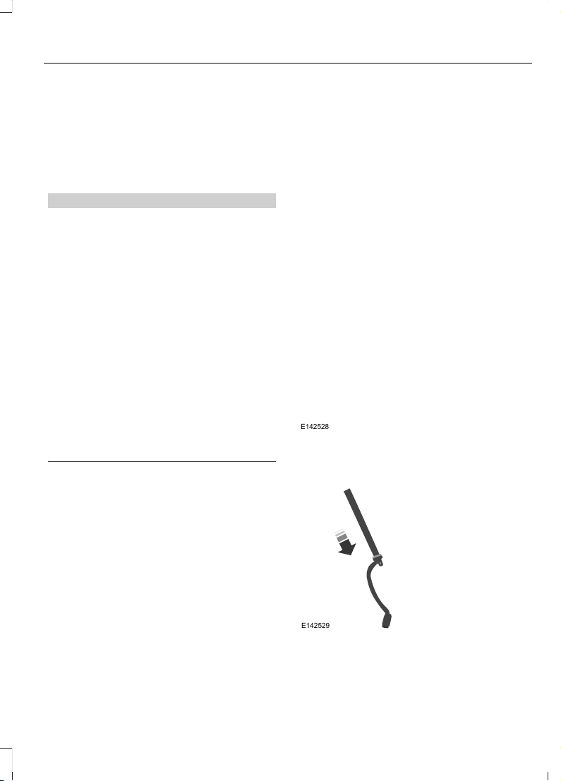
E142528
1. Position the child safety seat in a seat
with a combination lap and shoulder
belt.
E142529
2. Pull down on the shoulder belt and
then grasp the shoulder belt and lap
belt together.
21
Escape (TM2), enUSA, First Printing
Child Safety
Page 25
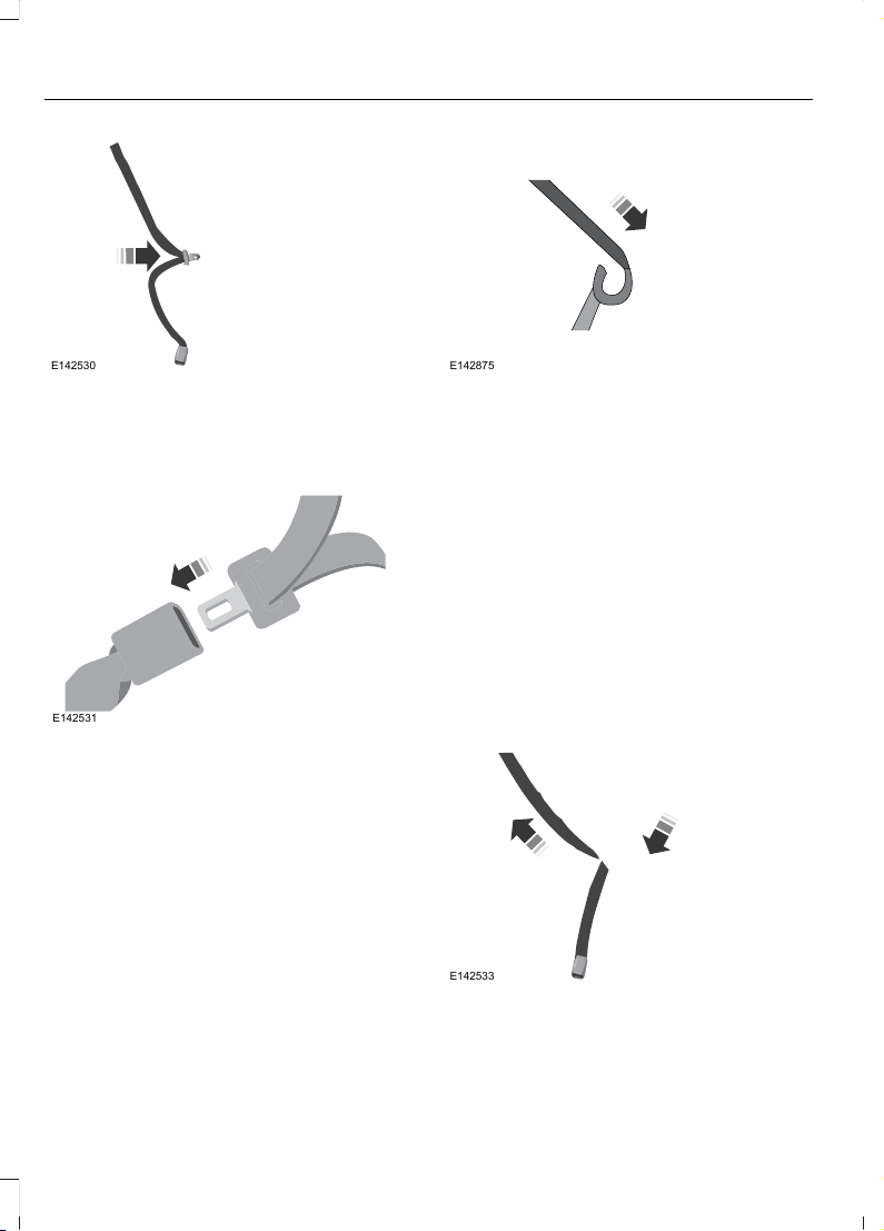
E142530
3. While holding the shoulder and lap belt
portions together, route the tongue
through the child seat according to the
child seat manufacturer's instructions.
Be sure the belt webbing is not twisted.
E142531
4. Insert the belt tongue into the proper
buckle (the buckle closest to the
direction the tongue is coming from)
for that seating position until you hear
a snap and feel the latch engage. Make
sure the tongue is latched securely by
pulling on it.
E142875
5. To put the retractor in the automatic
locking mode, grasp the shoulder
portion of the belt and pull downward
until all of the belt is pulled out.
Note: The automatic locking mode is
available on the front passenger and rear
seats.
6. Allow the belt to retract to remove
slack. The belt will click as it retracts
to indicate it is in the automatic locking
mode.
7. Try to pull the belt out of the retractor
to make sure the retractor is in the
automatic locking mode (you should
not be able to pull more belt out). If the
retractor is not locked, unbuckle the
belt and repeat Steps 5 and 6.
E142533
22
Escape (TM2), enUSA, First Printing
Child Safety
Page 26
8. Remove remaining slack from the belt.
Force the seat down with extra weight,
for example, by pressing down or
kneeling on the child restraint while
pulling up on the shoulder belt in order
to force slack from the belt. This is
necessary to remove the remaining
slack that will exist once the extra
weight of the child is added to the child
restraint. It also helps to achieve the
proper snugness of the child seat to
your vehicle. Sometimes, a slight lean
toward the buckle will additionally help
to remove remaining slack from the
belt.
9. Attach the tether strap (if the child seat
is equipped).
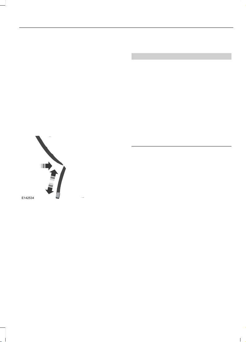
E142534
10. Before placing the child in the seat,
forcibly move the seat forward and
back to make sure the seat is securely
held in place. To check this, grab the
seat at the belt path and attempt to
move it side to side and forward and
back. There should be no more than
1 inch (2.5 centimeters) of movement
for proper installation.
Ford recommends checking with a NHTSA
Certified Child Passenger Safety
Technician to make certain the child
restraint is properly installed. In Canada,
check with your local St. John Ambulance
office for referral to a Certified Passenger
Seat Technician.
Using Lower Anchors and Tethers
for CHildren (LATCH)
WARNINGS
Never attach two child safety seats
to the same anchor. In a crash, one
anchor may not be strong enough to
hold two child safety seat attachments
and may break, causing serious injury or
death.
Depending on where you secure a
child restraint, and depending on the
child restraint design, you may block
access to certain safety belt buckle
assemblies or LATCH lower anchors,
rendering those features potentially
unusable. To avoid risk of injury, occupants
should only use seating positions where
they are able to be properly restrained.
The LATCH system is composed of three
vehicle anchor points: two lower anchors
located where seat back and seat cushion
meet (called the seat bight) and one top
tether anchor located behind that seating
position.
LATCH compatible child safety seats have
two rigid or webbing mounted
attachments that connect to the two lower
anchors at the LATCH equipped seating
positions in your vehicle. This type of
attachment method eliminates the need
to use safety belts to attach the child seat,
however the safety belt can still be used
to attach the child seat. For forward-facing
child seats, the top tether strap must also
be attached to the proper top tether
anchor, if a top tether strap has been
provided with your child seat.
23
Escape (TM2), enUSA, First Printing
Child Safety
Page 27
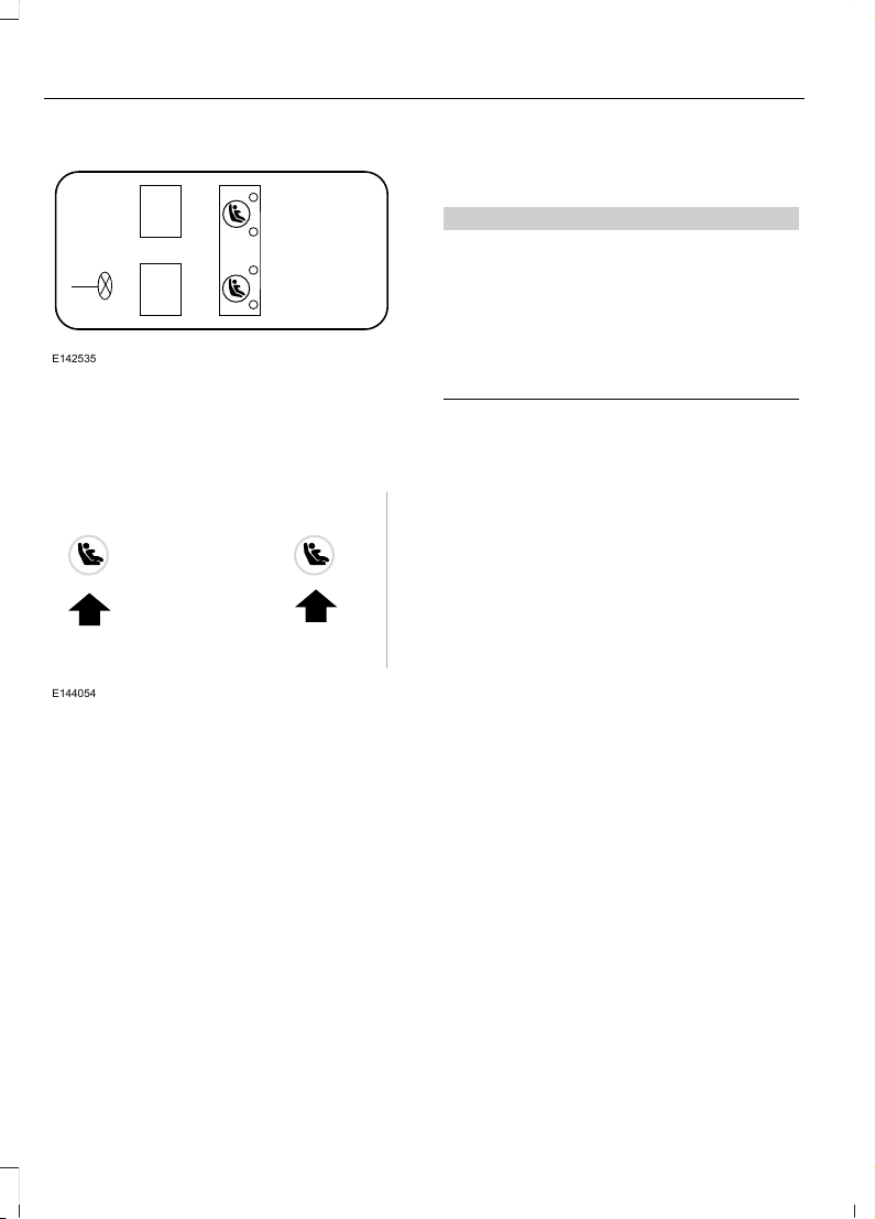
E142535
Your vehicle has LATCH lower anchors for
child seat installation at the seating
positions marked with the child seat
symbol.
E144054
The LATCH anchors are located at the rear
section of the rear seat between the
cushion and seat back below the symbols
as shown. Follow the child seat
manufacturer's instructions to properly
install a child seat with LATCH
attachments. Follow the instructions on
attaching child safety seats with tether
straps.
Attach LATCH lower attachments of the
child seat only to the anchors shown.
Use of Inboard Lower Anchors from the
Outboard Seating Positions (Center
Seating Use)
WARNING
The standardized spacing for LATCH
lower anchors is 11 inches (28
centimeters) center to center. Do not
use LATCH lower anchors for the center
seating position unless the child seat
manufacturer's instructions permit and
specify using anchors spaced at least as
far apart as those in this vehicle.
The lower anchors at the center of the
second row rear seat are spaced 18 inches
(46 centimeters) apart. A child seat with
rigid LATCH attachments cannot be
installed at the center seating position.
LATCH compatible child seats (with
attachments on belt webbing) can only be
used at this seating position provided that
the child seat manufacturer's instructions
permit use with the anchor spacing stated.
Do not attach a child seat to any lower
anchor if an adjacent child seat is attached
to that anchor.
Each time you use the safety seat, check
that the seat is properly attached to the
lower anchors and tether anchor, if
applicable. Tug the child seat from side to
side and forward and back where it is
secured to your vehicle. The seat should
move less than one inch when you do this
for a proper installation.
If the safety seat is not anchored properly,
the risk of a child being injured in a crash
greatly increases.
24
Escape (TM2), enUSA, First Printing
Child Safety
Page 28
Combining Safety Belt and LATCH
Lower Anchors for Attaching Child
Safety Seats
When used in combination, either the
safety belt or the LATCH lower anchors
may be attached first, provided a proper
installation is achieved. Attach the tether
strap afterward, if included with the child
seat.
Using Tether Straps
Many forward-facing child safety
seats include a tether strap
which extends from the back of
the child safety seat and hooks to an
anchoring point called the top tether
anchor. Tether straps are available as an
accessory for many older safety seats.
Contact the manufacturer of your child
seat for information about ordering a
tether strap, or to obtain a longer tether
strap if the tether strap on your safety seat
does not reach the appropriate top tether
anchor in your vehicle.
Once the child safety seat has been
installed using either the safety belt, the
lower anchors of the LATCH system, or
both, you can attach the top tether strap.
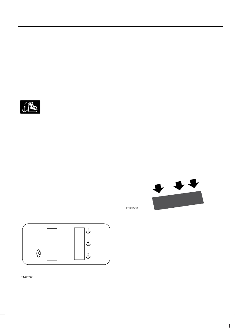
The tether strap anchors in your vehicle
are in the following positions (shown from
top view):
E142537
Perform the following steps to install a
child safety seat with tether anchors:
Note: If you install a child seat with rigid
LATCH attachments, do not tighten the
tether strap enough to lift the child seat off
your vehicle seat cushion when the child is
seated in it. Keep the tether strap just snug
without lifting the front of the child seat.
Keeping the child seat just touching your
vehicle seat gives the best protection in a
severe crash.
1. Route the child safety seat tether strap
over the back of the seat. For outboard
seating positions, route the tether strap
under the head restraint and between
the head restraint posts. For the center
seating positions, route the tether strap
over the top of the head restraint. If
needed, the head restraints can also
be removed.
E142538
2. Locate the correct anchor on the back
panel of the rear seat for the selected
seating position. The anchors are
labeled with the tether strap symbol
and are partially covered by the gap
panel. Pull the panel back to fully
expose the anchors.
25
Escape (TM2), enUSA, First Printing
Child Safety
Page 29
E142539
3. Clip the tether strap to the anchor as
shown.
4. Tighten the child safety seat tether
strap according to the manufacturer's
instructions. If your child restraint
system is equipped with a tether strap,
and the child restraint manufacturer
recommends its use, Ford also
recommends its use.
BOOSTER SEATS
WARNING
Never place, or allow a child to place,
the shoulder belt under a child's arm
or behind the back because it
reduces the protection for the upper part
of the body and may increase the risk of
injury or death in a crash.
Use a belt-positioning booster seat for
children who have outgrown or no longer
properly fit in a child safety seat (generally
children who are less than 4 feet 9 inches
(1.45 meters) tall, are greater than age four
(4) and less than age twelve (12), and
between 40 pounds (18 kilograms) and
80 pounds (36 kilograms) and upward to
100 pounds (45 kilograms) if
recommended by your child restraint
manufacturer). Many state and provincial
laws require that children use approved
booster seats until they reach age eight, a
height of 4 feet 9 inches (1.45 meters) tall,
or 80 pounds (36 kilograms).
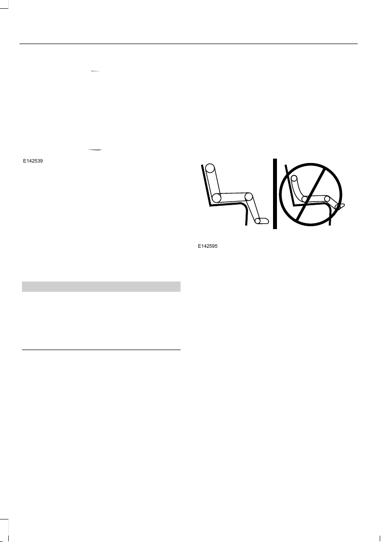
Booster seats should be used until you can
answer YES to ALL of these questions
when seated without a booster seat:
E142595
• Can the child sit all the way back
against their vehicle seat back with
knees bent comfortably at the edge of
the seat cushion?
• Can the child sit without slouching?
• Does the lap belt rest low across the
hips?
• Is the shoulder belt centered on the
shoulder and chest?
• Can the child stay seated like this for
the whole trip?
Always use booster seats in conjunction
with your vehicle lap and shoulder belt.
26
Escape (TM2), enUSA, First Printing
Child Safety
Page 30
Types of Booster Seats
E68924
• Backless booster seats
If your backless booster seat has a
removable shield, remove the shield. If a
vehicle seating position has a low seat
back or no head restraint, a backless
booster seat may place your child's head
(as measured at the tops of the ears)
above the top of the seat. In this case,
move the backless booster to another
seating position with a higher seat back or
head restraint and lap and shoulder belts,
or consider using a high back booster seat.
E70710
• High back booster seats
If, with a backless booster seat, you cannot
find a seating position that adequately
supports your child's head, a high back
booster seat would be a better choice.
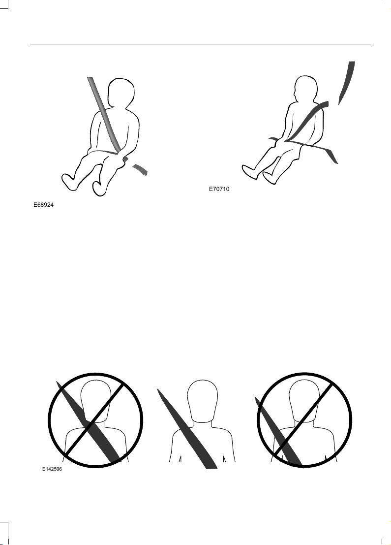
Children and booster seats vary in size and
shape. Choose a booster that keeps the
lap belt low and snug across the hips,
never up across the stomach, and lets you
adjust the shoulder belt to cross the chest
and rest snugly near the center of the
shoulder. The following drawings compare
the ideal fit (center) to a shoulder belt
uncomfortably close to the neck and a
shoulder belt that could slip off the
shoulder. The drawings also show how the
lap belt should be low and snug across the
child's hips.
E142596
27
Escape (TM2), enUSA, First Printing
Child Safety
Page 31

E142597
If the booster seat slides on the vehicle
seat upon which it is being used, placing a
rubberized mesh sold as shelf or carpet
liner under the booster seat may improve
this condition. Do not introduce any item
thicker than this under the booster seat.
Check with the booster seat
manufacturer's instructions.
CHILD SEAT POSITIONING
WARNINGS
Airbags can kill or injure a child in a
child seat. Never place a rear-facing
child seat in front of an active airbag.
If you must use a forward-facing child seat
in the front seat, move the vehicle seat
upon which the child seat is installed all
the way back. When possible, all children
age 12 and under should be properly
restrained in a rear seating position. If all
children cannot be seated and restrained
properly in a rear seating position, properly
restrain the largest child in the front seat.
Always carefully follow the
instructions and warnings provided
by the manufacturer of any child
restraint to determine if the restraint device
is appropriate for your child's size, height,
weight, or age. Follow the child restraint
manufacturer's instructions and warnings
provided for installation and use in
conjunction with the instructions and
WARNINGS
warnings provided by your vehicle
manufacturer. A safety seat that is
improperly installed or utilized, is
inappropriate for your child's height, age,
or weight or does not properly fit the child
may increase the risk of serious injury or
death.
Never let a passenger hold a child on
his or her lap while your vehicle is
moving. The passenger cannot
protect the child from injury in a crash,
which may result in serious injury or death.
Never use pillows, books, or towels
to boost a child. They can slide
around and increase the likelihood
of injury or death in a crash.
Always restrain an unoccupied child
seat or booster seat. These objects
may become projectiles in a crash or
sudden stop, which may increase the risk
of serious injury.
Never place, or allow a child to place,
the shoulder belt under a child's arm
or behind the back because it
reduces the protection for the upper part
of the body and may increase the risk of
injury or death in a crash.
To avoid risk of injury, do not leave
children or pets unattended in your
vehicle.
28
Escape (TM2), enUSA, First Printing
Child Safety
Page 32

Recommendations for attaching child safety restraints for children
Use any attachment method as indicated below by XCombined
weight of
child and
child seat
Restraint
Type
Safety belt
only
Safety belt
and LATCH
(lower
anchors
and top
tether
anchor)
Safety belt
and top
tether
anchor
LATCH
(lower
anchors
only)
LATCH
(lower
anchors
and top
tether
anchor)
XXUp to 65 lb
(29 kg)
Rear facing
child seat
XOver 65 lb
(29 kg)
Rear facing
child seat
XXXUp to 65 lb
(29 kg)
Forward
facing
child seat
XXOver 65 lb
(29 kg)
Forward
facing
child seat
Note: The child seat must rest tightly
against the vehicle seat upon which it is
installed. It may be necessary to lift or
remove the head restraint. See Seats (page
111).
CHILD SAFETY LOCKS
When these locks are set, the rear doors
cannot be opened from the inside.
E112197
The childproof locks are located on the
rear edge of each rear door and must be
set separately for each door.
29
Escape (TM2), enUSA, First Printing
Child Safety
Page 33

Left-Hand Side
Turn counterclockwise to lock and
clockwise to unlock.
Right-Hand Side
Turn clockwise to lock and
counterclockwise to unlock.
30
Escape (TM2), enUSA, First Printing
Child Safety
Page 34

PRINCIPLE OF OPERATION
WARNINGS
Always drive and ride with your
seatback upright and the lap belt
snug and low across the hips.
To reduce the risk of injury, make
sure children sit where they can be
properly restrained.
Never let a passenger hold a child on
his or her lap while your vehicle is
moving. The passenger cannot
protect the child from injury in a crash.
All occupants of your vehicle,
including the driver, should always
properly wear their safety belts, even
when an airbag supplemental restraint
system is provided.
It is extremely dangerous to ride in a
cargo area, inside or outside of a
vehicle. In a crash, people riding in
these areas are more likely to be seriously
injured or killed. Do not allow people to ride
in any area of your vehicle that is not
equipped with seats and safety belts. Be
sure everyone in your vehicle is in a seat
and using a safety belt properly.
In a rollover crash, an unbelted
person is significantly more likely to
die than a person wearing a safety
belt.
Each seating position in your vehicle
has a specific safety belt assembly
which is made up of one buckle and
one tongue that are designed to be used
as a pair. 1) Use the shoulder belt on the
outside shoulder only. Never wear the
shoulder belt under the arm. 2) Never
swing the safety belt around your neck over
the inside shoulder. 3) Never use a single
belt for more than one person.
When possible, all children 12 years
old and under should be properly
restrained in a rear seating position.
WARNINGS
Safety belts and seats can become
hot in a vehicle that has been closed
up in sunny weather; they could burn
a small child. Check seat covers and
buckles before you place a child anywhere
near them.
Front and rear seat occupants,
including pregnant women, should
wear safety belts for optimum
protection in an accident.
All seating positions in this vehicle have
lap and shoulder safety belts. All
occupants of the vehicle should always
properly wear their safety belts, even when
an airbag supplemental restraint system
is provided.
The safety belt system consists of:
• lap and shoulder safety belts
• shoulder safety belt with automatic
locking mode, (except driver safety
belt)
• height adjuster at the front outboard
seating positions
• retractor and anchor pretensioner at
the front outboard seating positions
• belt tension sensor at the front
outboard passenger seating position
• safety belt warning light and chime
• crash sensors and monitoring system
with readiness indicator.
31
Escape (TM2), enUSA, First Printing
Safety Belts
Page 35

The safety belt pretensioners are designed
to activate in frontal, near-frontal and side
crashes, and in rollovers. The safety belt
pretensioners on the retractor and anchor
at the front seating positions are designed
to tighten the safety belts firmly against
the occupant's body when activated. This
helps increase the effectiveness of the
safety belts. In frontal crashes, the safety
belt pretensioners can be activated alone
or, if the crash is of sufficient severity,
together with the front airbags.
FASTENING THE SAFETY BELTS
The front outboard and rear safety
restraints in the vehicle are combination
lap and shoulder belts.
E142587
1. Insert the belt tongue into the proper
buckle (the buckle closest to the
direction the tongue is coming from)
until you hear a snap and feel it latch.
Make sure the tongue is securely
fastened in the buckle.
E142588
2. To unfasten, press the release button
and remove the tongue from the
buckle.
E142589
When in use, the rear safety belts should
be placed in the belt guides on the
outboard seatbacks.
Using Safety Belts During
Pregnancy
WARNING
Always ride and drive with your
seatback upright and the safety belt
properly fastened. The lap portion of
the safety belt should fit snug and be
positioned low across the hips. The
shoulder portion of the safety belt should
be positioned across the chest. Pregnant
women should also follow this practice.
See the following figure.
32
Escape (TM2), enUSA, First Printing
Safety Belts
Page 36

E142590
Pregnant women should always wear their
safety belt. The lap belt portion of a
combination lap and shoulder belt should
be positioned low across the hips below
the belly and worn as tight as comfort will
allow. The shoulder belt should be
positioned to cross the middle of the
shoulder and the center of the chest.
Safety Belt Locking Modes
WARNINGS
After any vehicle crash, the safety
belt system at all passenger seating
positions must be checked by an
authorized dealer to verify that the
automatic locking retractor feature for
child seats is still functioning properly. In
addition, all safety belts should be checked
for proper function.
BELT AND RETRACTOR ASSEMBLY
MUST BE REPLACED if the safety
belt assembly automatic locking
retractor feature or any other safety belt
function is not operating properly when
checked by an authorized dealer. Failure
to replace the belt and retractor assembly
could increase the risk of injury in crashes.
All safety restraints in the vehicle are
combination lap and shoulder belts. The
driver safety belt has the first type of
locking mode, and the front outboard
passenger and rear seat safety belts have
both types of locking modes described as
follows:
Vehicle Sensitive Mode
This is the normal retractor mode, which
allows free shoulder belt length
adjustment to your movements and
locking in response to vehicle movement.
For example, if the driver brakes suddenly
or turns a corner sharply, or the vehicle
receives an impact of about 5 mph
(8 km/h) or more, the combination safety
belts will lock to help reduce forward
movement of the driver and passengers.
In addition, the retractor is designed to lock
if the webbing is pulled out too quickly. If
this occurs, let the belt retract slightly and
pull webbing out again in a slow and
controlled manner.
Automatic Locking Mode
In this mode, the shoulder belt is
automatically pre-locked. The belt will still
retract to remove any slack in the shoulder
belt. The automatic locking mode is not
available on the driver safety belt.
When to Use the Automatic Locking
Mode
This mode should be used any time a child
safety seat, except a booster, is installed
in passenger front or rear seating positions.
Children 12 years old and under should be
properly restrained in a rear seating
position whenever possible. See Child
Safety (page 19).
33
Escape (TM2), enUSA, First Printing
Safety Belts
Page 37

How to Use the Automatic Locking
Mode
E142591
1. Buckle the combination lap and
shoulder belt.
2. Grasp the shoulder portion and pull
downward until the entire belt is pulled
out.
Allow the belt to retract. As the belt
retracts, you will hear a clicking sound. This
indicates the safety belt is now in the
automatic locking mode.
How to Disengage the Automatic
Locking Mode
Unbuckle the combination lap and
shoulder belt and allow it to retract
completely to disengage the automatic
locking mode and turn on the vehicle
sensitive (emergency) locking mode.
How to Extract Safety Belts in the
Rear Outboard Positions
Safety belts in the rear outboard positions
can lock if the seatback is returned firmly
to its upright position. You can unlock the
safety belts using the following
procedures.
For vehicles where the rear seats recline:
1. Recline the seat to its full rear recline
position.
2. The safety belt should then unlock.
3. Return the seatback to its desired
upright position.
For vehicles with rear seats that do not
recline or are locked with the seat in its full
rear recline position:
1. Grasp the safety belt webbing at the
top of the seatback.
2. Pull the safety belt webbing forward,
firmly.
3. After pulling the safety belt forward,
allow the safety belt to feed back into
the safety belt retractor as much as
possible. If necessary, press the
seatback down to allow the safety belt
webbing to retract further.
4. The safety belt should then unlock.
5. If the safety belt does not unlock,
repeat steps 1-3.
Safety Belt Extension Assembly
WARNING
Do not use extensions to change the
fit of the shoulder belt across the
torso.
If the safety belt is too short when fully
extended, you can obtain a safety belt
extension assembly from an authorized
dealer.
Use only extensions manufactured by the
same supplier as the safety belt.
Manufacturer identification is on a label
located either at the end of the webbing
or on the retractor behind the trim. Also,
use the safety belt extension only if the
safety belt is too short for you when fully
extended.
34
Escape (TM2), enUSA, First Printing
Safety Belts
Page 38

SAFETY BELT HEIGHT ADJUSTMENT
WARNING
Position the safety belt height
adjusters so that the belt rests
across the middle of your shoulder.
Failure to adjust the safety belt correctly
could reduce the effectiveness of the
safety belt and increase the risk of injury in
a crash.
E87511
To adjust the shoulder belt height, squeeze
the button and slide the height adjuster up
or down. Release the button and pull down
on the height adjuster to make sure it is
locked in place.
SAFETY BELT WARNING LAMP AND INDICATOR CHIME
This lamp illuminates and an
audible warning will sound if the
driver's safety belt has not been
fastened when the vehicle's ignition is
turned on.
Conditions of operation
Then...If...
The safety belt warning light illuminates 1-
2 minutes and the warning chime sounds
4-8 seconds.
The driver's safety belt is not buckled
before the ignition switch is turned to the
on position...
The safety belt warning light and warning
chime turn off.
The driver's safety belt is buckled while the
indicator light is illuminated and the
warning chime is sounding...
The safety belt warning light and indicator
chime remain off.
The driver's safety belt is buckled before
the ignition switch is turned to the on posi-
tion...
35
Escape (TM2), enUSA, First Printing
Safety Belts
Page 39

SAFETY BELT MINDER
Belt-Minder™
This feature supplements the safety belt
warning function by providing additional
reminders that intermittently sound a tone
and illuminate the safety belt warning light
when you are in the driver seat or you have
a front seat passenger and a safety belt is
unbuckled.
The system uses information from the
front passenger sensing system to
determine if a front seat passenger is
present and therefore potentially in need
of a warning. To avoid activating the
Belt-Minder feature for objects you place
in the front passenger seat, only the front
seat passengers receive warnings as
determined by the front passenger sensing
system.
If the Belt-Minder warnings expire
(warnings for about five minutes) for one
passenger (driver or front passenger), the
other passenger can still cause the
Belt-Minder feature to turn on.
Then...If...
The Belt-Minder feature will not activate.You and the front seat passenger buckle
your safety belts before you switch the
ignition on or less than 1-2 minutes elapse
after you switch the ignition on...
The Belt-Minder feature activates, the
safety belt warning light illuminates and a
warning tone sounds for 6 seconds every
25 seconds, repeating for about 5 minutes
or until you and the front seat passenger
buckle your safety belts.
You or the front seat passenger do not
buckle your safety belts before your vehicle
reaches at least 6 mph (9.7 km/h) and 1-2
minutes elapse after you switch the ignition
on...
The Belt-Minder feature activates, the
safety belt warning light illuminates and a
warning tone sounds for 6 seconds every
25 seconds, repeating for about 5 minutes
or until you and the front seat passenger
buckle your safety belts.
The safety belt for the driver or front
passenger is unbuckled for about 1 minute
while the vehicle is traveling at least 6 mph
(9.7 km/h) and more than 1-2 minutes
elapse after you switch the ignition on...
36
Escape (TM2), enUSA, First Printing
Safety Belts
Page 40

Deactivating and Activating the
Belt-Minder Feature
WARNING
While the system allows you to
deactivate it, this system is designed
to improve your chances of being
safely belted and surviving an accident.
We recommend you leave the system
activated for yourself and others who may
use your vehicle.
Note: The driver and front passenger
warnings switch on and off independently.
When you perform this procedure for one
seating position, do not buckle the other
position as this will terminate the process.
Read Steps 1 - 4 thoroughly before
proceeding with the programming
procedure.
Before following the procedure, make sure
that:
• The parking brake is set.
• The transmission is in park (P).
• The ignition is off.
• The driver and front passenger safety
belts are unbuckled.
1. Switch the ignition on. Do not start the
engine.
2. Wait until the safety belt warning light
turns off (about one minute). After
Step 2, wait an additional five seconds
before proceeding with Step 3. Once
you start Step 3, you must complete
the procedure within 60 seconds.
3. For the seating position you are
switching off, buckle then unbuckle the
safety belt three times at a moderate
speed, ending in the unbuckled state.
After Step 3, the safety belt warning
light turns on.
4. While the safety belt warning light is
on, buckle and then unbuckle the
safety belt. After Step 4, the safety belt
warning light flashes for confirmation.
• This will switch the feature off for that
seating position if it is currently on.
• This will switch the feature on for that
seating position if it is currently off.
CHILD RESTRAINT AND SAFETY BELT MAINTENANCE
Inspect the vehicle safety belts and child
safety seat systems periodically to make
sure they work properly and are not
damaged. Inspect the vehicle and child
seat safety belts to make sure there are no
nicks, tears or cuts. Replace if necessary.
All vehicle safety belt assemblies, including
retractors, buckles, front safety belt buckle
assemblies, buckle support assemblies
(slide bar-if equipped), shoulder belt
height adjusters (if equipped), shoulder
belt guide on seat back (if equipped), child
safety seat LATCH and tether anchors, and
attaching hardware, should be inspected
after a crash. Read the child restraint
manufacturer's instructions for additional
inspection and maintenance information
specific to the child restraint.
Ford Motor Company recommends that
all safety belt assemblies in use in vehicles
involved in a crash be replaced. However,
if the crash was minor and an authorized
dealer finds that the belts do not show
damage and continue to operate properly,
they do not need to be replaced. Safety
belt assemblies not in use during a crash
should also be inspected and replaced if
either damage or improper operation is
noted.
Properly care for safety belts. See Vehicle
Care (page 231).
37
Escape (TM2), enUSA, First Printing
Safety Belts
Page 41

The Personal Safety System provides an
improved overall level of frontal crash
protection to front seat occupants and is
designed to help further reduce the risk of
airbag-related injuries. The system is able
to analyze different occupant conditions
and crash severity before activating the
appropriate safety devices to help better
protect a range of occupants in a variety
of frontal crash situations.
The Vehicle Personal Safety System
consists of:
• Driver and passenger dual-stage airbag
supplemental restraints.
• Front seat outboard safety belts with
pretensioners, energy management
retractors and safety belt usage
sensors.
• Driver seat position sensor.
• Front passenger sensing system.
• Passenger airbag off and on indicator
lamp.
• Front crash severity sensors.
• Restraints control module with impact
and safing sensors.
• Restraint system warning light and
backup tone.
• The electrical wiring for the airbags,
crash sensors, safety belt
pretensioners, front safety belt usage
sensors, driver seat position sensor,
front passenger sensing system and
indicator lights.
How Does the Personal Safety
System Work?
The Personal Safety System can adapt the
deployment strategy of the safety devices
according to crash severity and occupant
conditions. A collection of crash and
occupant sensors provides information to
the restraints control module. During a
crash, the restraints control module may
deploy the safety belt pretensioners, one
or both stages of the dual-stage airbags
based on crash severity and occupant
conditions.
38
Escape (TM2), enUSA, First Printing
Personal Safety System™
Page 42

PRINCIPLE OF OPERATION
WARNINGS
Airbags do not inflate slowly or
gently, and the risk of injury from a
deploying airbag is the greatest close
to the trim covering the airbag module.
All occupants of your vehicle,
including the driver, should always
properly wear their safety belts, even
when an airbag supplemental restraint
system is provided. Failure to properly wear
your safety belt could seriously increase
the risk of injury or death.
Always transport children 12 years
old and under in the back seat and
always properly use appropriate
child restraints. Failure to follow this could
seriously increase the risk of injury or death.
Never place your arm over the airbag
module as a deploying airbag can
result in serious arm fractures or
other injuries.
Airbags can kill or injure a child in a
child seat. Never place a rear-facing
child seat in front of an active airbag.
If you must use a forward-facing child seat
in the front seat, move the seat upon which
the child seat is installed all the way back.
Do not attempt to service, repair, or
modify the airbag supplemental
restraint systems or its fuses as you
could be seriously injured or killed. Contact
your authorized dealer as soon as possible.
Several airbag system components
get hot after inflation. Do not touch
them after inflation as this may result
in serious injury.
If the airbag has deployed, the airbag
will not function again and must be
replaced immediately. If the airbag
is not replaced, the unrepaired area will
increase the risk of injury in a crash.
The airbags are a supplemental restraint
system and are designed to work with the
safety belts to help protect the driver and
right front passenger from certain upper
body injuries. Airbags do not inflate slowly;
there is a risk of injury from a deploying
airbag.
Note: You will hear a loud bang and see a
cloud of harmless powdery residue if an
airbag deploys. This is normal.
The airbags inflate and deflate rapidly
upon activation. After airbag deployment,
it is normal to notice a smoke-like, powdery
residue or smell the burnt propellant. This
may consist of cornstarch, talcum powder
(to lubricate the bag) or sodium
compounds (for example, baking soda)
that result from the combustion process
that inflates the airbag. Small amounts of
sodium hydroxide may be present which
may irritate the skin and eyes, but none of
the residue is toxic.
While the system is designed to help
reduce serious injuries, contact with a
deploying airbag may also cause abrasions
or swelling. Temporary hearing loss is also
a possibility as a result of the noise
associated with a deploying airbag.
Because airbags must inflate rapidly and
with considerable force, there is the risk of
death or serious injuries such as fractures,
facial and eye injuries or internal injuries,
particularly to occupants who are not
properly restrained or are otherwise out of
position at the time of airbag deployment.
Thus, it is extremely important that
occupants be properly restrained as far
away from the airbag module as possible
while maintaining vehicle control.
Routine maintenance of the airbags is not
required.
39
Escape (TM2), enUSA, First Printing
Supplementary Restraints System
Page 43

DRIVER AND PASSENGER AIRBAGS
WARNINGS
Never place your arm or any objects
over an airbag module. Placing your
arm over a deploying airbag can
result in serious arm fractures or other
injuries. Objects placed on or over the
airbag inflation area may cause those
objects to be propelled by the airbag into
your face and torso causing serious injury.
Airbags can kill or injure a child in a
child seat. Never place a rear-facing
child seat in front of an active airbag.
If you must use a forward-facing child seat
in the front seat, move the seat upon which
the child seat is installed all the way back.
E151127
The driver and front passenger airbags will
deploy during significant frontal and near
frontal crashes.
The driver and passenger front airbag
system consists of:
• Driver and passenger airbag modules.
• Front passenger sensing system.
· Crash sensors and monitoring
system with readiness indicator.
See Crash Sensors and Airbag
Indicator (page 46).
Proper Driver and Front Passenger
Seating Adjustment
WARNING
National Highway Traffic Safety
Administration (NHTSA)
recommends a minimum distance
of at least 10 inches (25 centimeters)
between an occupant’s chest and the
driver airbag module.
To properly position yourself away from
the airbag:
• Move your seat to the rear as far as you
can while still reaching the pedals
comfortably.
• Recline the seat slightly (one or two
degrees) from the upright position.
After all occupants have adjusted their
seats and put on safety belts, it is very
important that they continue to sit
properly. A properly seated occupant sits
upright, leaning against the seat back, and
centered on the seat cushion, with their
feet comfortably extended on the floor.
Sitting improperly can increase the chance
of injury in a crash event. For example, if
an occupant slouches, lies down, turns
sideways, sits forward, leans forward or
sideways, or puts one or both feet up, the
chance of injury during a crash is greatly
increased.
Children and Airbags
WARNING
Airbags can kill or injure a child in a
child seat. Never place a rear-facing
child seat in front of an active airbag.
If you must use a forward-facing child seat
in the front seat, move the seat upon which
the child seat is installed all the way back.
40
Escape (TM2), enUSA, First Printing
Supplementary Restraints System
Page 44

E142846
Children must always be properly
restrained. Accident statistics suggest that
children are safer when properly restrained
in the rear seating positions than in the
front seating position. Failure to follow
these instructions may increase the risk of
injury in a crash.
FRONT PASSENGER SENSING SYSTEM
WARNINGS
Even with Advanced Restraints
Systems, children 12 and under
should be properly restrained in a
rear seating position. Failure to follow this
could seriously increase the risk of injury or
death.
Sitting improperly out of position or
with the seatback reclined too far
can take off weight from the seat
cushion and affect the decision of the front
passenger sensing system, resulting in
serious injury or death in a crash.
Always sit upright against your seat
back, with your feet on the floor.
Any alteration or modification to the
front passenger seat may affect the
performance of the front passenger
sensing system which could seriously
increase the risk of injury or death.
E145987
The indicator lamp is located in the center
stack of the instrument panel.
The front passenger sensing system is
designed to disable (will not inflate) the
front passenger frontal airbag under
certain conditions:
• The front passenger seat is
unoccupied.
• The system determines an infant is
present in a child restraint.
• A passenger takes their weight off the
seat for a period of time.
• If there is a problem with the airbag
system or the passenger sensing
system.
Even with this technology, parents are
strongly encouraged to always properly
restrain children in the rear seat.
41
Escape (TM2), enUSA, First Printing
Supplementary Restraints System
Page 45

• When the front passenger sensing
system disables (will not inflate) the
front passenger frontal airbag, the
passenger airbag status indicator will
illuminate and stay lit to remind you
that the front passenger frontal airbag
is disabled.
• If the passenger airbag status indicator
lamp indicates the passenger airbag is
enabled, after the child restraint has
been installed, turn the vehicle off,
remove the child restraint from the
vehicle and reinstall the restraint
following the child restraint
manufacturer’s instructions.
• If the passenger airbag status indicator
lamp continues to indicate the
passenger airbag is enabled, the child
should be properly restrained in a rear
seating position.
The front passenger sensing system works
with sensors that are part of the front
passenger seat and safety belt. The
sensors are designed to detect the
presence of a properly–seated occupant
and determine if the front passenger
frontal airbag should be enabled.
• When the front passenger sensing
system enables the front passenger
frontal airbag (may inflate), the
passenger airbag status indicator will
not illuminate.
If a person of adult size is sitting in the front
passenger seat, but the passenger airbag
is disabled, it is possible that the person is
not sitting properly in the seat. If this
happens:
• Turn the vehicle off and ask the person
to place the seatback in the full upright
position.
• Have the person sit upright in the seat,
centered on the seat cushion, with the
person's legs comfortably extended.
• Restart the vehicle and have the person
remain in this position for about two
minutes. This will allow the system to
detect that person and enable the
passenger’s frontal airbag.
• If the passenger airbag status indicator
lamp remains lit even after this, the
person should be advised to ride in the
rear seat.
Note: When the passenger airbag status
indicator lamp is illuminated, the passenger
side airbag (seat mounted) may be disabled
to avoid the risk of airbag deployment
injuries.
After all occupants have adjusted their
seats and put on safety belts, it is very
important that they continue to sit
properly. A properly seated occupant sits
upright, leaning against the seatback, and
centered on the seat cushion, with their
feet comfortably extended on the floor.
Sitting improperly can increase the chance
of injury in a crash event. For example, if
an occupant slouches, lies down, turns
sideways, sits forward, leans forward or
sideways, or puts one or both feet up, the
chance of injury during a crash is greatly
increased.
If you think that the status of the passenger
airbag off indicator lamp is incorrect, check
for the following:
• Objects lodged underneath the seat.
• Objects between the seat cushion and
the center console.
• Objects hanging off the seatback.
• Objects stowed in the seatback map
pocket.
• Objects placed on the occupant's lap.
• Cargo interference with the seat.
• Other passengers pushing or pulling on
the seat.
• Rear passenger feet and knees resting
or pushing on the seat.
42
Escape (TM2), enUSA, First Printing
Supplementary Restraints System
Page 46

The conditions listed above may cause the
weight of a properly seated occupant to
be incorrectly interpreted by the passenger
sensing system. The person in the front
passenger seat may appear heavier or
lighter due to the conditions described in
the list above.
Make sure the front passenger
sensing system is operating
properly. See Crash Sensors
and Airbag Indicator (page 46).
If the airbag readiness lamp is lit, do
the following:
Check for objects that are lodged
underneath the front passenger seat, or
cargo interfering with the seat.
If there are lodged objects, or cargo is
interfering with the seat, take the following
steps to remove the obstruction:
• Pull the vehicle over.
• Turn the vehicle off.
• Driver or adult passengers should
check for any objects lodged
underneath the front passenger seat
or cargo interfering with the seat.
• Remove the obstruction(s) (if found).
• Restart the vehicle.
• Wait at least two minutes and verify
that the airbag readiness lamp is no
longer illuminated.
• If the airbag readiness lamp remains
illuminated, this may or may not be a
problem due to the front passenger
sensing system.
Do not attempt to repair or service the
system; take your vehicle immediately to
an authorized dealer.
If it is necessary to modify an advanced
front airbag system to accommodate a
person with disabilities, contact your
authorized dealer.
SIDE AIRBAGS
WARNINGS
Do not place objects or mount
equipment on or near the airbag
cover, on the side of the seatbacks
(of the front seats), or in front seat areas
that may come into contact with a
deploying airbag. Failure to follow these
instructions may increase the risk of
personal injury in the event of a crash.
Do not use accessory seat covers.
The use of accessory seat covers
may prevent the deployment of the
side airbags and increase the risk of injury
in an accident.
Do not lean your head on the door.
The side airbag could injure you as it
deploys from the side of the
seatback.
Do not attempt to service, repair, or
modify the airbag, its fuses or the
seat cover on a seat containing an
airbag as you could be seriously injured or
killed. Contact your authorized dealer as
soon as possible.
If the side airbag has deployed, the
airbag will not function again. The
side airbag system (including the
seat) must be inspected and serviced by
an authorized dealer. If the airbag is not
replaced, the unrepaired area will increase
the risk of injury in a crash.
The side airbags are located on the
outboard side of the seatbacks of the front
seats. In certain sideways crashes, the
airbag on the side affected by the crash
will be inflated. The airbag was designed
to inflate between the door panel and
occupant to further enhance the protection
provided occupants in side impact crashes.
43
Escape (TM2), enUSA, First Printing
Supplementary Restraints System
Page 47

E152533
The system consists of the following:
• A label or embossed side panel
indicating that side airbags are fitted
to your vehicle.
• Side airbags located inside the driver
and front passenger seatbacks.
• Front passenger sensing system.
·Crash sensors and monitoring
system with readiness indicator.
See Crash Sensors and Airbag
Indicator (page 46).
Note: The passenger sensing system will
deactivate the passenger seat-mounted
side airbag if it detects an empty passenger
seat.
The design and development of the side
airbag system included recommended
testing procedures that were developed
by a group of automotive safety experts
known as the Side Airbag Technical
Working Group. These recommended
testing procedures help reduce the risk of
injuries related to the deployment of side
airbags.
DRIVER KNEE AIRBAG
A driver's knee airbag is located under the
instrument panel. During a crash, the
restraints control module may activate the
driver's knee airbag based on crash severity
and occupant conditions. Under certain
crash and occupant conditions, the driver’s
knee airbag may deploy but the driver’s
front airbag may not activate. As with front
and side airbags, it is important to be
properly seated and restrained to reduce
the risk of death or serious injury.
Make sure the knee airbag is
operating properly. See Crash
Sensors and Airbag Indicator
(page 46).
SAFETY CANOPY™
WARNINGS
Do not place objects or mount
equipment on or near the headliner
at the siderail that may come into
contact with a deploying curtain airbag.
Failure to follow these instructions may
increase the risk of personal injury in the
event of a crash.
Do not lean your head on the door.
The curtain airbag could injure you
as it deploys from the headliner.
Do not attempt to service, repair, or
modify the curtain airbags, its fuses,
the A, B, or C pillar trim, or the
headliner on a vehicle containing curtain
airbags as you could be seriously injured
or killed. Contact your authorized dealer
as soon as possible.
44
Escape (TM2), enUSA, First Printing
Supplementary Restraints System
Page 48

WARNINGS
All occupants of your vehicle
including the driver should always
wear their safety belts even when an
airbag supplemental restraint system and
curtain airbag is provided. Failure to
properly wear your safety belt could
seriously increase the risk of injury or death.
To reduce risk of injury, do not
obstruct or place objects in the
deployment path of the curtain
airbag.
If the curtain airbags have deployed,
the curtain airbags will not function
again. The curtain airbags (including
the A, B and C pillar trim and headliner)
must be inspected and serviced by an
authorized dealer. If the curtain airbag is
not replaced, the unrepaired area will
increase the risk of injury in a crash.
The Safety Canopy will deploy during
significant side crashes or when a certain
likelihood of a rollover event is detected
by the rollover sensor. The Safety Canopy
is mounted to the roof side-rail sheet
metal, behind the headliner, above each
row of seats. In certain sideways crashes
or rollover events, the Safety Canopy will
be activated, regardless of which seats are
occupied. The Safety Canopy is designed
to inflate between the side window area
and occupants to further enhance
protection provided in side impact crashes
and rollover events.
E75004
The system consists of the following:
• Safety canopy curtain airbags located
above the trim panels over the front
and rear side windows identified by a
label or wording on the headliner or
roof-pillar trim.
• A flexible headliner which opens above
the side doors to allow air curtain
deployment
• The crash sensors and monitoring
system have a readiness indicator. See
Crash Sensors and Airbag Indicator
(page 46).
Children 12 years old and under should
always be properly restrained in the rear
seats. The Safety Canopy will not interfere
with children restrained using a properly
installed child or booster seat because it
is designed to inflate downward from the
headliner above the doors along the side
window opening.
The design and development of the Safety
Canopy included recommended testing
procedures that were developed by a
group of automotive safety experts known
as the Side Airbag Technical Working
Group. These recommended testing
procedures help reduce the risk of injuries
related to the deployment of side airbags
(including the Safety Canopy).
45
Escape (TM2), enUSA, First Printing
Supplementary Restraints System
Page 49

CRASH SENSORS AND AIRBAG INDICATOR
WARNING
Modifying or adding equipment to
the front end of the vehicle (including
frame, bumper, front end body
structure and tow hooks) may affect the
performance of the airbag system,
increasing the risk of injury. Do not modify
the front end of the vehicle.
Your vehicle has a collection of crash and
occupant sensors which provide
information to the restraints control
module. The restraints control module
deploys (activates) the front safety belt
pretensioners, driver airbag, passenger
airbag, knee airbag(s), seat mounted side
airbags and Safety Canopy airbags. Based
on the type of crash (frontal impact or side
impact), the restraints control module will
deploy the appropriate safety devices.
The restraints control module also
monitors the readiness of the above safety
devices plus the crash and occupant
sensors. The readiness of the safety
system is indicated by a warning indicator
light in the instrument cluster or by a
backup tone if the warning light is not
working. Routine maintenance of the
airbag is not required.
A difficulty with the system is indicated by
one or more of the following:
The readiness light will not
illuminate immediately after the
ignition is turned on.
• The readiness light will either flash or
stay lit.
• A series of five beeps will be heard. The
tone pattern will repeat periodically
until the problem, the light or both are
repaired.
If any of these things happen, even
intermittently, have the supplemental
restraint system serviced at an authorized
dealer immediately. Unless serviced, the
system may not function properly in the
event of a crash.
The safety belt pretensioners and the front
airbag supplemental restraint system are
designed to activate when the vehicle
sustains frontal deceleration sufficient to
cause the restraints control module to
deploy a safety device.
The fact that the safety belt pretensioners
or front airbags did not activate for both
front seat occupants in a crash does not
mean that something is wrong with the
system. Rather, it means the restraints
control module determined the accident
conditions (crash severity, belt usage)
were not appropriate to activate these
safety devices.
• The design of the front airbags is to
activate only in frontal and near-frontal
crashes (not rollovers, side impacts or
rear impacts) unless the crash causes
sufficient frontal deceleration.
• The safety belt pretensioners are
designed to activate in frontal,
near-frontal and side crashes.
• The knee airbag(s) may deploy based
on crash severity and occupant
conditions.
• The design of the side airbags is to
inflate in certain side crashes. The
design of the Safety Canopy is to
inflate in certain side impact crashes
and when a certain likelihood of
rollover is detected by the rollover
sensor. Side airbags and Safety Canopy
airbags may activate in other types of
crashes if the vehicle experiences
sufficient sideways motion or
deformation.
46
Escape (TM2), enUSA, First Printing
Supplementary Restraints System
Page 50

AIRBAG DISPOSAL
Contact your authorized dealer as soon as
possible. Airbags must be disposed of by
qualified personnel.
47
Escape (TM2), enUSA, First Printing
Supplementary Restraints System
Page 51

PRINCIPLE OF OPERATION
The remote control allows you to:
• Remotely lock or unlock the vehicle
doors.
• Unlock the doors without actively using
a key or remote control (intelligent
access only).
• Remotely open the power liftgate (if
equipped).
• Remotely start or stop the engine and
user pre-set features (if equipped).
• Arm and disarm the anti-theft system.
• Activate the panic alarm.
GENERAL INFORMATION ON RADIO FREQUENCIES
This device complies with Part 15 of the
FCC Rules and with Industry Canada
license-exempt RSS standard(s).
Operation is subject to the following two
conditions: (1) This device may not cause
harmful interference, and (2) This device
must accept any interference received,
including interference that may cause
undesired operation.
Note: Changes or modifications not
expressively approved by the party
responsible for compliance could void the
user's authority to operate the equipment.
The term IC before the radio certification
number only signifies that Industry Canada
technical specifications were met.
The typical operating range for your
transmitter is approximately 33 feet (10
meters). Vehicles with the remote start
feature will have a greater range. One of
the following could cause a decrease in
operating range:
• Weather conditions.
• Nearby radio towers.
• Structures around the vehicle.
• Other vehicles parked next to your
vehicle.
The radio frequency used by your remote
control can also be used by other short
distance radio transmissions, for example
amateur radios, medical equipment,
wireless headphones, remote controls and
alarm systems. If the frequencies are
jammed, you will not be able to use your
remote control. You can lock and unlock
the doors with the key.
Note: Make sure to lock your vehicle before
leaving it unattended.
Note: If you are in range, the remote control
will operate if you press any button
unintentionally.
Intelligent Access (If Equipped)
The system uses a radio frequency signal
to communicate with your vehicle and
authorize your vehicle to unlock when one
of the following conditions are met:
• You activate the front exterior door
handle switch.
• You press the luggage compartment
button.
• You press a button on the transmitter.
If excessive radio frequency interference
is present in the area or if the transmitter
battery is low, you may need to
mechanically unlock your door. You can
use the mechanical key blade in your
intelligent access key to open the driver
door in this situation. See Remote
Control (page 49).
48
Escape (TM2), enUSA, First Printing
Keys and Remote Controls
Page 52

REMOTE CONTROL
Integrated Keyhead Transmitters
(If Equipped)
E142585
Use the key blade to start your vehicle and
unlock or lock the driver door from outside
your vehicle. The transmitter portion
functions as the remote control.
E138615
Note: Your vehicle’s keys came with a
security label that provides important
vehicle key cut information. Keep the label
in a safe place for future reference.
Intelligent Access Key (If Equipped)
Note: A three-button remote control will
operate similarly.
E138616
Your intelligent access keys operate the
power locks and the remote start system.
The key must be in your vehicle to activate
the push-button start system.
E142431
The intelligent access key also contains a
removable mechanical key blade that you
can use to unlock the driver door. Slide the
release on the back of the transmitter to
release the key blade, then pull the blade
out.
E138618
Note: Your vehicle’s back-up keys came
with a security tag that provides important
vehicle key cut information. Keep the tag in
a safe place for future reference.
Replacing the Battery
Note: Refer to local regulations when
disposing of transmitter batteries.
Note: Do not wipe off any grease on the
battery terminals or on the back surface of
the circuit board.
49
Escape (TM2), enUSA, First Printing
Keys and Remote Controls
Page 53

Note: Replacing the battery will not delete
the transmitter from the vehicle. The
transmitter should operate normally.
The remote control uses one coin-type
three-volt lithium battery CR2032 or
equivalent.
Integrated Keyhead Transmitter
E138619
1. Twist a thin coin in the slot of the
transmitter near the key ring to remove
the battery cover.
2. Remove the old battery.
E138620
3. Insert the new battery. Refer to the
instructions inside the transmitter for
the correct orientation of the battery.
Press the battery down to make sure
it is fully in the housing.
4. Snap the battery cover back onto the
transmitter.
Intelligent Access Transmitter
1. Remove the backup key from the
transmitter.
E142432
2. Twist a thin coin under the tab hidden
behind the backup key head to remove
the battery cover. Do not use the
backup key to remove the cover or you
could damage the intelligent access
key.
E138622
3. Remove the old battery.
4. Insert a new battery with the + facing
downward. Press the battery down to
make sure it is fully in the housing.
5. Snap the battery cover back onto the
transmitter and install the backup key.
Car Finder
E138623
Press the button twice within
three seconds. The horn will
sound and the turn signals will
flash. We recommend you use this method
to locate your vehicle, rather than using
the panic alarm.
50
Escape (TM2), enUSA, First Printing
Keys and Remote Controls
Page 54

Note: If locking was not successful or if any
door or the liftgate is open, or if the hood is
open on vehicles with a perimeter alarm or
remote start, the horn will sound twice and
the lamps will not flash.
Sounding a Panic Alarm
Note: The panic alarm will only operate
when the ignition is off.
E138624
Press the button to activate the
alarm. Press the button again or
turn the ignition on to deactivate.
Remote Start (If Equipped)
WARNING
To avoid exhaust fumes, do not use
remote start if your vehicle is parked
indoors or areas that are not well
ventilated.
Note: Do not use remote start if your vehicle
is low on fuel.
E138625
The remote start button is on the
transmitter.
This feature allows you to start your
vehicle from outside the vehicle. The
transmitter has an extended operating
range.
Vehicles with automatic climate control
can be configured to operate when the
vehicle is remote started. See Automatic
Climate Control (page 104).
Many states and provinces have
restrictions for the use of remote start.
Check your local and state or provincial
laws for specific requirements regarding
remote start systems.
The remote start system will not work if:
• the ignition is on
• the alarm system is triggered
• you disable the feature
• the hood is open
• the transmission is not in P
• the vehicle battery voltage is too low
• the service engine soon indicator was
on the last time your vehicle was
driven.
Remote Starting the Vehicle
Note: You must press each button within
three seconds of each other. Your vehicle
will not remote start and the horn will not
sound if you do not follow this sequence.
E138626
The label on your transmitter details the
starting procedure.
To remote start your vehicle:
1. Press the lock button to lock all the
doors.
2. Press the remote start button twice.
The exterior lamps will flash twice.
The horn will sound if the system fails to
start, unless quiet start is on. Quiet start
will run the blower fan at a slower speed
to reduce noise. You can switch it on or off
in the information display. See General
Information (page 90).
Note: If you remote start your vehicle with
an integrated keyhead transmitter, you must
switch the ignition on before driving your
vehicle. If you remote start your vehicle with
an intelligent access transmitter, you must
press the START/STOP button on the
instrument panel once while applying the
brake pedal before driving your vehicle.
51
Escape (TM2), enUSA, First Printing
Keys and Remote Controls
Page 55

The power windows will be inhibited during
the remote start and the radio will not turn
on automatically.
The parking lamps will remain on and the
vehicle will run for 5, 10, or 15 minutes,
depending on the setting.
Extending the Vehicle Run Time
Repeat Steps 1 and 2 with the vehicle still
running to extend the run time for another
remote start duration. If the duration is set
to last 10 minutes, the duration will extend
by another 10 minutes. For example, if the
vehicle had been running from the first
remote start for five minutes, the vehicle
will continue to run now for a total of 20
minutes. You can only extend the remote
start once. Some late build vehicles may
be able to restart up to 30 minutes.
Wait at least five seconds before remote
starting after a vehicle shutdown.
Turning the Vehicle Off After Remote
Starting
E138625
Press the button once. The
parking lamps will turn off.
You may have to be closer to the
vehicle than when starting due to ground
reflection and the added noise of the
running vehicle.
You can disable or enable the remote start
system through the information display.
See General Information (page 90).
REPLACING A LOST KEY OR REMOTE CONTROL
Replacement keys or remote controls can
be purchased from an authorized dealer.
Authorized dealers can program remote
controls for your vehicle. See Passive
Anti-Theft System (page 67).
To re-program the passive anti-theft
system see an authorized dealer.
52
Escape (TM2), enUSA, First Printing
Keys and Remote Controls
Page 56

PRINCIPLE OF OPERATION
MyKey allows you to program keys with
restricted driving modes to promote good
driving habits. All but one of the keys
programmed to the vehicle can be
activated with these restricted modes.
Any keys that have not been programmed
are referred to as administrator keys or
admin keys. These can be used to:
• Create a MyKey.
• Program configurable MyKey settings.
• Clear all MyKey features.
When you have created a MyKey, you can
access the following information using the
information display:
• How many admin keys and MyKeys are
programmed to your vehicle.
• The total distance your vehicle has
traveled using any MyKey.
Note: All MyKeys are programmed to the
same settings. You cannot program them
individually.
Note: For vehicles with keyless start, when
both a MyKey transmitter and an admin
transmitter are present, the admin
transmitter will be recognized by the vehicle
to start the engine.
Non-configurable Settings
The following settings cannot be changed
by an admin key user:
• Belt-minder. You cannot disable this
feature. The audio system will mute
when the safety belts are not fastened.
• Early low fuel warning. The low-fuel
warning activates earlier, giving the
MyKey user more time to refuel.
• Driver assist features, if equipped on
your vehicle, are forced on: parking aid,
blind spot information system (BLIS)
with cross traffic alert, lane departure
warning and forward collision warning
system.
• Satellite radio adult content
restrictions.
Configurable Settings
With an admin key, you can configure
certain MyKey settings when you first
create a MyKey and before you recycle the
key or restart the vehicle. You can also
change the settings afterward with an
admin key:
• Vehicle speed limits can be set.
Warnings will be shown in the display
followed by an audible tone when your
vehicle reaches the set speed. You
cannot override the set speed by fully
depressing the accelerator pedal.
• Vehicle speed minders. Once you select
a speed, it will be shown in the display
followed by a tone when the set vehicle
speed is exceeded.
• Audio system maximum volume of
45%. A message will be shown in the
display when you attempt to exceed
the limited volume. Also, the speed
sensitive compensated volume
(automatic volume control) feature
will be disabled.
• Always on setting. When this is
selected you will not be able to disable
AdvanceTrac, 911 Assist or the do not
disturb feature (if your vehicle is
equipped with these features).
CREATING A MYKEY
Use the information display to create a
MyKey:
53
Escape (TM2), enUSA, First Printing
MyKey™
Page 57

1. Insert the key you want to program into
the ignition. If your vehicle is equipped with
a push-button start, hold the intelligent
access key next to the steering column.
Details on the correct fob placement and
position is in another chapter. See
Starting and Stopping the Engine (page
125).
2. Switch the ignition on.
3. Access the main menu on the
information display controls, and select
Settings and then MyKey by pressing OK
or the > button.
4. Press OK or the > button to select
Create MyKey.
5. When prompted, hold the OK button
until you see a message informing you to
label this key as a MyKey. The key will be
restricted at your vehicle's next start.
MyKey is successfully created. Make sure
you label it so you can distinguish it from
the admin keys.
You can also program configurable
settings for the key(s). Refer to
Programming/Changing Configurable
Settings.
Programming/Changing
Configurable Settings
Use the information display to access your
configurable MyKey settings:
1. Switch the ignition on using an admin
key or fob.
2. Access the main menu on the
information display controls, and select
Settings, then MyKey by pressing OK
or the > button.
3. Use the arrow buttons to get to a
configurable feature.
4. Press OK or > to make a selection.
Note: You can clear or change your MyKey
settings at any time during the same key
cycle as you created the MyKey. Once you
have switched the engine off, however, you
will need an admin key to change or clear
your MyKey settings.
CLEARING ALL MYKEYS
You can clear or change your MyKey
settings using the information display
control on the steering wheel. See
Information Displays (page 90).
Switch the ignition on using an admin key
or fob.
To clear all MyKeys of all MyKey settings, press the left arrow button to access
the main menu and scroll to:
Action and DescriptionMessage
Press the OK button.Settings
Press the OK button.MyKey
Press and hold the OK button until the following message
displays.
Clear MyKey
All MyKeys
Cleared
Note: When you clear your MyKeys, you remove all restrictions and return all MyKeys to
their original admin key status.
54
Escape (TM2), enUSA, First Printing
MyKey™
Page 58

CHECKING MYKEY SYSTEM STATUS
You can find information on programmed
MyKey(s) using the information display
control on the steering wheel. See
Information Displays (page 90).
To find information on a programed MyKey(s), press the left arrow button to
access the main menu and scroll to:
DescriptionMessage
Press the OK button.Settings
Press the OK button.MyKey
Select one of the following:
Tracks the distance when drivers use a MyKey. The only way
to delete the accumulated distance is by using an admin key
to clear your MyKey. If the distance does not accumulate as
expected, then the intended user is not using the MyKey, or
an admin key user recently cleared and then recreated a
MyKey.
MyKey Dist.
Indicates the number of MyKeys programed to your vehicle.
Use this feature to detect how many MyKeys you have for
your vehicle and determine when a MyKey has been deleted.
{0} MyKeys
Indicates how many admin keys are programed to your
vehicle. Use this feature to determine how many unrestricted
keys you have for your vehicle, and detect if an additional
MyKey has been programed.
{0} Admin Keys
55
Escape (TM2), enUSA, First Printing
MyKey™
Page 59

USING MYKEY WITH REMOTE START SYSTEMS
MyKey is not compatible with non
Ford-approved, aftermarket remote start
systems. If you choose to install a remote
start system, see an authorized dealer for
a Ford-approved remote start system.
MYKEY TROUBLESHOOTING
Potential CausesCondition
I cannot create a MyKey. • The key or transmitter used to start the
vehicle does not have admin privileges.
• The key or transmitter used to start the
vehicle is the only admin key (there always
has to be at least one admin key).
• Vehicles with keyless start: The keyless
start transmitter is not placed in the backup
slot, located in the center console. See
Keyless Entry (page 65).
• SecuriLock passive anti-theft system is
disabled or in unlimited mode.
• The key or transmitter used to start your
vehicle does not have admin privileges.
• No MyKeys are created. See Creating a
MyKey (page 53).
I cannot program the configurable
settings.
• The key or transmitter used to start your
vehicle does not have admin privileges.
• No MyKeys are created. See Creating a
MyKey (page 53).
I cannot clear the MyKeys.
Purchase a new key from an authorized dealer.I lost the only admin key.
56
Escape (TM2), enUSA, First Printing
MyKey™
Page 60

Potential CausesCondition
Program a spare key. See Passive Anti-Theft
System (page 67).
I lost a key.
MyKey distances do not accumulate. • The MyKey user is not using the MyKey.
• An admin key holder cleared the MyKeys
and created new MyKeys.
• The key system has been reset.
• An admin transmitter is present at vehicle
start.
• No MyKeys are created. See Creating a
MyKey (page 53).
No MyKey functions with the keyless
entry transmitter.
57
Escape (TM2), enUSA, First Printing
MyKey™
Page 61

LOCKING AND UNLOCKING
You can use the power door lock control
or the remote control to lock and unlock
your vehicle.
Power Door Locks
The power door lock control is on the driver
and front passenger door panels.
E138628
UnlockA
LockB
Door Lock Indicator
An LED on the instrument panel will light
when you lock the doors. It is not a
functional control.
Remote Control
Unlocking the Doors (Two-Stage
Unlock)
E138629
Press the button to unlock the
driver door.
Press the button again within
three seconds to unlock all doors. The turn
signals will flash.
Press and hold both the lock and unlock
buttons on the remote control for four
seconds to disable or enable two-stage
unlocking. Disabling two-stage unlocking
allows all vehicle doors to unlock with one
press of the button. The turn signals will
flash twice to indicate a change to the
unlocking mode. The unlocking mode
applies to the remote control, keyless entry
keypad and intelligent access.
Intelligent access at the driver door will
unlock all doors when you disable
two-stage unlocking.
Locking the Doors
E138623
Press the button to lock all the
doors. The turn signals will flash.
Press the button again within
three seconds to confirm that all the doors
are closed. The doors will lock again, the
horn will sound and the turn signals will
flash if all the doors and the luggage
compartment are closed.
Note: If locking was not successful or any
door or the liftgate is open, or if the hood is
open on vehicles with a perimeter alarm or
remote start, the horn will sound twice and
the lamps will not flash.
Liftgate
WARNINGS
Make sure all persons are clear of the
liftgate area before using the liftgate
control.
Make sure to close and latch the
liftgate to prevent drawing exhaust
fumes into your vehicle. This will also
prevent passengers and cargo from falling
out. If you must drive with the liftgate open,
keep the vents or windows open so outside
air comes into your vehicle. Failure to
follow this warning could result in serious
personal injury.
58
Escape (TM2), enUSA, First Printing
Locks
Page 62

Note: Be careful when opening or closing
the liftgate in a garage or other enclosed
area to avoid damaging the liftgate.
E138630
Press twice within three seconds
to:
• unlatch a manual liftgate
• open, close or stop the movement of
a power liftgate. See Power Liftgate
(page 63).
Mechanical Key
Turn the top of the key toward the front of
your vehicle once to lock all doors.
Turn the top of the key toward the rear of
your vehicle once to unlock the driver door
only.
Locking the Doors Individually
If the power locks fail to operate, lock the
doors individually using the key in the
position shown.
E112203
Left-Hand Side
Turn clockwise to lock.
Right-Hand Side
Turn counterclockwise to lock.
Opening a Rear Door from Inside
Pull the interior door release handle twice
to unlock and open a rear door. The first
pull unlocks the door and the second pull
will unlatch the door.
Activating Intelligent Access (If
Equipped)
The intelligent access key must be within
3 feet (1 meter) of your vehicle.
At the Front Doors
Pull a front exterior door handle to unlock
and open the door. The unlock sensor is on
the back of the handle. Make sure not to
touch the lock sensor area on the front of
the handle.
E87384
Press and hold the lock sensor area for
about a second to lock your vehicle. To
avoid unlocking the door inadvertently,
make sure you only touch the lock sensor
and not other areas of the door handle.
After locking the doors with the lock
sensor, there is a brief delay before you can
unlock your vehicle. This delay lets you pull
the handle to make sure it locked.
Note: Keep the door handle surface clean
to avoid issues with operation.
59
Escape (TM2), enUSA, First Printing
Locks
Page 63

At the Liftgate
Press the exterior liftgate release button
on the top of the liftgate pull-cup handle.
Smart Unlocks For Integrated
Keyhead Transmitter
This feature helps to prevent you from
locking yourself out of your vehicle if your
key is still in the ignition.
When you open one of the front doors and
lock your vehicle with the power door lock
control, all the doors will lock then unlock
if your key is still in the ignition.
You can still lock your vehicle with the key
in the ignition by either:
• using the keyless entry keypad with the
driver door closed
• pressing the lock button on the
transmitter even if the doors are not
closed.
If both front doors are closed, you can lock
your vehicle by any method, regardless of
whether the key is in the ignition or not.
Smart Unlocks For Intelligent
Access Keys (If Equipped)
This feature helps to prevent you from
unintentionally locking your intelligent
access key inside your vehicle’s passenger
compartment or rear cargo area.
When you lock your vehicle using the
power door lock control (with the door
open, vehicle in park and ignition off), your
vehicle will search for an intelligent access
key in the passenger compartment after
you close the door. If you vehicle finds a
key, all of the doors will immediately
unlock.
In order to override the smart unlock
feature and intentionally lock the
intelligent access key inside your vehicle,
you can lock your vehicle after all doors
are closed by using the keyless entry
keypad, pressing the lock button on
another intelligent access key or touching
the locking area on the handle with another
intelligent access key in your hand.
When you open one of the front doors and
lock your vehicle using the power door lock
control, all doors will lock then unlock if
the ignition is on.
Autolock (If Equipped)
The autolock feature will lock all the doors
when:
• all doors are closed,
• the ignition is on,
• you shift into any gear putting your
vehicle in motion, and
• your vehicle attains a speed greater
than 4 mph (7 km/h).
Autounlock (If Equipped)
The autounlock feature will unlock all the
doors when:
• the ignition is on, all the doors are
closed, and your vehicle has been in
motion at a speed greater than 4 mph
(7 km/h);
• your vehicle comes to a stop and you
switch the ignition off or to accessory;
and
• you open the driver door within 10
minutes of the switching the ignition
off or to accessory.
Note: The doors will not autounlock if you
electronically lock your vehicle after you
switch the ignition off and before you open
the driver door.
60
Escape (TM2), enUSA, First Printing
Locks
Page 64

Enabling or Disabling Autolock and
Autounlock
Note: Your authorized dealer can perform
this procedure, or you can do the procedure
yourself.
To enable or disable these features, do the
following:
Note: You will have 30 seconds to
complete the procedure.
1. Switch the ignition on.
2. Press the power door unlock button
three times.
3. Switch the ignition off.
4. Press the power door unlock button
three times.
5. Switch the ignition on. The horn will
sound indicating your vehicle is in
programming mode.
Autolock: Press the power door unlock
button then the lock button. The horn will
sound once if disabled or twice (one short
and one long) if enabled.
Autounlock: Press the power door lock
button then the unlock button. The horn
will sound once if disabled or twice (one
short and one long) if enabled.
After programming the feature, switch the
ignition off. The horn will sound once
indicating programming is complete.
Note: You can enable or disable the
autounlock feature independently of the
autolock feature.
Illuminated Entry
The interior lamps and select exterior
lamps will illuminate when you unlock the
doors with the remote entry system.
The illuminated entry system will turn off
the lights if:
• you start your vehicle,
• you press the remote control lock
button, or
• after 25 seconds of illumination.
The lights will not turn off if:
• you turn them on with the lamp control,
or
• any door is open.
Illuminated Exit
The interior lamps and select exterior
lamps will illuminate when all doors are
closed and you switch the ignition off.
The lamps will turn off if all the doors
remain closed and:
• 25 seconds elapse, or
• you lock your vehicle from the outside.
Battery Saver
If you leave the courtesy lamps or dome
lamps on and switch the ignition off, the
battery saver shuts them off after some
time.
Accessory Mode Battery Saver for
Intelligent Access Keys (If Equipped)
If you leave the ignition on after leaving
your vehicle, it will shut off 15 minutes after
you close all of the doors.
61
Escape (TM2), enUSA, First Printing
Locks
Page 65

MANUAL LIFTGATE
WARNINGS
It is extremely dangerous to ride in a
cargo area, inside or outside of a
vehicle. In a crash, people riding in
these areas are more likely to be seriously
injured or killed. Do not allow people to ride
in any area of your vehicle that is not
equipped with seats and safety belts. Be
sure everyone in your vehicle is in a seat
and using a safety belt properly. Failure to
follow this warning could result in serious
personal injury or death.
Make sure to close and latch the
liftgate to prevent drawing exhaust
fumes into your vehicle. This will also
prevent passengers and cargo from falling
out. If you must drive with the liftgate open,
keep the vents or windows open so outside
air comes into your vehicle. Failure to
follow this warning could result in serious
personal injury.
Note: Be careful when opening or closing
the liftgate in a garage or other enclosed
area to avoid damaging the liftgate.
Note: Do not hang anything, for example a
bike rack, from the glass or liftgate. This
could damage the liftgate and its
components.
Note: Do not leave the liftgate open while
driving. This could damage the liftgate and
its components.
Opening the Liftgate
Manually
E138632
Press the button located in the top of the
liftgate pull cup handle to unlatch the
liftgate, and then pull on the outside
handle.
With the Remote Control
E138630
Press the button twice within
three seconds.
Closing the Liftgate
E155976
A handle is located inside the liftgate to
help with closing.
62
Escape (TM2), enUSA, First Printing
Locks
Page 66

POWER LIFTGATE (If Equipped)
WARNINGS
It is extremely dangerous to ride in a
cargo area, inside or outside of a
vehicle. In a collision, people riding in
these areas are more likely to be seriously
injured or killed. Do not allow people to ride
in any area of your vehicle that is not
equipped with seats and safety belts. Be
sure everyone in your vehicle is in a seat
and using a safety belt properly.
Make sure to close and latch the
liftgate to prevent drawing exhaust
fumes into your vehicle. This will also
prevent passengers and cargo from falling
out. If you must drive with the liftgate open,
keep the vents or windows open so outside
air comes into your vehicle. Failure to
follow this warning could result in serious
personal injury.
Keep keys out of reach of children.
Do not allow children to play near an
open or moving power liftgate.
Note: Cycling the ignition while the liftgate
is power closing and is near the latch may
cause the liftgate to reverse to full open
position. Make sure that you close the
liftgate before operating or moving the
vehicle, especially in an enclosure, like a
garage or a parking structure. You could
damage the liftgate or its components.
Note: Do not hang anything, for example a
bike rack, from the spoiler, glass or liftgate.
This could damage the liftgate and its
components.
If the vehicle is running, the liftgate only
operates with the transmission in P.
Three warning tones sound once as the
liftgate begins to power close. Five short
chimes indicate a problem with the open
or close request, caused by:
• The ignition is on and the transmission
is not in P.
• The battery voltage is below the
minimum operating voltage.
• The vehicle speed is at or above 3 mph
(5 km/h).
If the liftgate falls to the closed direction
after the liftgate has stopped in the open
position, four short warning chimes
indicate excessive weight on the gate or a
possible gas strut failure. Have the system
checked by an authorized dealer if you still
have the issue after you remove the load.
Opening and Closing the Liftgate
(If Equipped)
WARNING
Make sure all persons are clear of the
power liftgate area before using the
power liftgate control.
Note: Be careful when opening or closing
the liftgate in a garage or other enclosed
area to avoid damaging the liftgate.
Note: Do not leave the liftgate open while
driving. This could damage the liftgate and
its components.
Note: You can stop the liftgate movement
direction with a second press of the
instrument panel button or the control
button on the liftgate, a second double
press of the transmitter button, or by using
a kicking motion with your foot for
hands-free liftgates.
From the Instrument Panel
E189530
Press the instrument panel
button.
With the Remote Control
E138630
Press the remote control button
twice within three seconds.
63
Escape (TM2), enUSA, First Printing
Locks
Page 67

Hands-Free Feature
Make sure you have an intelligent access
transmitter within 3 ft (1 m) of the liftgate.
E161602
2
1
1. Move your foot under and away from
the rear bumper similar to a kicking
motion. Do not move your foot
sideways or the sensors may not detect
the motion. For vehicles equipped with
both the hands-free liftgate and trailer
tow, move your foot under the bumper
between the trailer hitch and the
exhaust.
2. The liftgate powers open or close.
Note: Allow the power system to open the
liftgate. Manually pushing or pulling the
liftgate may activate the system’s obstacle
detection feature and stops the power
operation.
Note: Splashing water may cause the
hands-free liftgate to open. Keep the
intelligent access transmitter away from the
rear bumper detection area while washing
your car.
With the Outside Control Button
Opening
1. Unlock the liftgate with the remote
control or power door unlock control.
If an intelligent access transmitter is
within 3 ft (1 m) of the liftgate, the
liftgate unlocks when you press the
liftgate release button.
E138632
2. Press the control button located in the
top of the liftgate pull-cup handle.
Note: Allow the power system to open the
liftgate after pressing the control. Manually
pushing or pulling the liftgate may activate
the system’ s obstacle detection feature and
stops the power operation.
Closing
E138636
Press and release the button.
64
Escape (TM2), enUSA, First Printing
Locks
Page 68

WARNING
Keep clear of the liftgate when
activating the rear switch.
Setting the Liftgate Open Height
1. Open the liftgate.
2. Manually move the liftgate to the
desired height.
3. Press and hold the control button on
the liftgate until you hear a chime,
indicating programming is complete.
Note: You cannot program the height if the
liftgate position is too low.
The system recalls the new open liftgate
height when the power liftgate is opened.
To change the programmed height, repeat
the above procedure. Once you open the
power liftgate, you can manually move it
to a different height.
When operating the power liftgate after
you have programmed a lower height than
full-open, you can fully open the liftgate
by manually pushing it upward to the
maximum open position.
Obstacle Detection
When Closing
The system stops when it detects an
obstacle and two short tones sound. Once
you remove the obstacle, you can power
close the liftgate.
Note: Entering your vehicle while the
liftgate is closing can cause your vehicle to
bounce and activate obstacle detection. To
prevent this, let the power liftgate close
completely before you enter your vehicle.
Before driving off, check the instrument
cluster for a liftgate or door ajar message or
warning indicator. Failure to do this could
result in unintentionally leaving the liftgate
open while driving.
When Opening
The system stops when it detects an
obstacle and two short tones sound.
Remove the obstacle to operate the
liftgate.
KEYLESS ENTRY (If Equipped)
SECURICODE™ KEYLESS ENTRY
KEYPAD
The keypad is located near the driver
window. It is invisible until touched and
then it lights up so you can see and touch
the appropriate buttons.
Note: If you enter your entry code too fast
on the keypad, the unlock function may not
work. Re-enter your entry code more slowly.
E138637
You can use the keypad to:
• lock or unlock the doors
• program and erase user codes
• arm and disarm the anti-theft alarm.
65
Escape (TM2), enUSA, First Printing
Locks
Page 69

You can operate the keypad with the
factory-set five-digit entry code. The code
is located on the owner’s wallet card in the
glove box and is available from an
authorized dealer. You can also create up
to five of your own five-digit personal entry
codes.
Programming a Personal Entry Code
To create your own personal entry code:
1. Enter the factory-set code.
2. Press 1·2 on the keypad within five
seconds.
3. Enter your personal five-digit code. You
must enter each number within five
seconds of each other.
4. Press 1·2 on the keypad to save
personal code 1.
The doors will lock then unlock to confirm
that programming was successful.
To program additional personal entry
codes, repeat Steps 1-3, then for Step 4:
• press 3·4 to save personal code 2
• press 5·6 to save personal code 3
• press 7·8 to save personal code 4
• press 9·0 to save personal code 5.
Tips:
• Do not set a code that uses five of the
same number.
• Do not use five numbers in sequential
order.
• The factory-set code will work even if
you have set your own personal code.
Erasing a Personal Code
1. Enter the factory-set five-digit code.
2. Press and release 1·2 on the keypad
within five seconds.
3. Press and hold 1·2 for two seconds.
This must be done within five seconds
of completing Step 2.
All personal codes will erase and only the
factory-set five-digit code will work.
Anti-Scan Feature
The keypad will go into an anti-scan mode
if you enter the wrong code seven times
(35 consecutive button presses). This
mode disables the keypad for one minute
and the keypad lamp will flash.
The anti-scan feature will turn off after:
• one minute of keypad inactivity
• pressing the unlock button on the
remote control
• switching the ignition on
• unlocking the vehicle using intelligent
access.
Unlocking and Locking the Doors
To Unlock the Driver Door
Enter the factory-set five-digit code or your
personal code. You must press each
number within five seconds of each other.
The interior lamps will illuminate.
Note: All doors will unlock if the two-stage
unlocking feature is disabled. See Locking
and Unlocking (page 58).
To Unlock All Doors
Enter the factory-set code or your personal
code, then press 3·4 control within five
seconds.
To Lock All Doors
Press and hold 7·8 and 9·0 at the same
time with the driver door closed. You do
not need to enter the keypad code first.
66
Escape (TM2), enUSA, First Printing
Locks
Page 70

PASSIVE ANTI-THEFT SYSTEM
Note: The system is not compatible with
non-Ford aftermarket remote start systems.
Use of these systems may result in vehicle
starting problems and a loss of security
protection.
Note: Metallic objects, electronic devices
or a second coded key on the same key
chain may cause vehicle starting problems
if they are too close to the key when starting
the engine. Prevent these objects from
touching the coded key while starting the
engine. Switch the ignition off, move all
objects on the key chain away from the
coded key and restart the engine if a
problem occurs.
Note: Do not leave a duplicate coded key
in the vehicle. Always take your keys and
lock all doors when leaving the vehicle.
SecuriLock®
The system is an engine immobilization
system. It is designed to help prevent the
engine from being started unless a coded
key programmed to your vehicle is used.
Using the wrong key may prevent the
engine from starting. A message may
appear in the information display.
If you are unable to start the engine with a
correctly coded key, a malfunction has
happened and a message may appear in
the information display.
Automatic Arming
The vehicle arms immediately after you
switch the ignition off.
Automatic Disarming
Switching the ignition on with a coded key
disarms the vehicle.
Replacement Keys
Note: Your vehicle comes equipped with
two integrated keyhead transmitters or two
intelligent access keys.
The integrated keyhead transmitter
functions as a programmed ignition key
that operates all the locks and starts the
vehicle, as well as a remote control.
The intelligent access key functions as a
programmed key that operates the driver
door lock and activates the intelligent
access with push button start system, as
well as a remote control.
If your programmed transmitters or
standard SecuriLock coded keys
(integrated keyhead transmitters only) are
lost or stolen and you do not have an extra
coded key, you will need to have your
vehicle towed to an authorized dealer. You
need to erase the key codes from your
vehicle and program new coded keys.
Store an extra programmed key away from
the vehicle in a safe place to help prevent
any inconveniences. See your authorized
dealer to purchase additional spare or
replacement keys.
Programming a Spare Integrated
Keyhead Transmitter
Note: You can program a maximum of eight
coded keys to your vehicle. All eight can be
integrated keyhead transmitters.
You can program your own integrated
keyhead transmitter or standard
SecuriLock coded keys to your vehicle. This
procedure will program both the engine
immobilizer keycode and the remote entry
portion of the remote control to your
vehicle
Only use integrated keyhead transmitters
or standard SecuriLock keys.
67
Escape (TM2), enUSA, First Printing
Security
Page 71

You must have two previously
programmed coded keys and the new
unprogrammed key readily accessible. See
your authorized dealer to have the spare
key programmed if two previously
programmed coded keys are not available.
Read and understand the entire procedure
before you begin.
1. Insert the first previously programmed
coded key into the ignition.
2. Switch the ignition from off to on. Keep
the ignition on for at least three
seconds, but no more than 10 seconds.
3. Switch the ignition off and remove the
first coded key from the ignition.
4. After three seconds but within 10
seconds of switching the ignition off,
insert the second previously coded key
into the ignition.
5. Switch the ignition from off to on. Keep
the ignition on for at least three
seconds, but no more than 10 seconds.
6. Switch the ignition off and remove the
second previously programmed coded
key from the ignition.
7. After three seconds but within 10
seconds of switching the ignition off
and removing the previously
programmed coded key, insert the new
unprogrammed key into the ignition.
8. Switch the ignition from off to on. Keep
the ignition on for at least six seconds.
9. Remove the newly programmed coded
key from the ignition.
If the key has been successfully
programmed it will start the engine and
operate the remote entry system (if the
new key is an integrated keyhead
transmitter).
If programming was not successful, wait
10 seconds and repeat Steps 1 through 8.
If you are still unsuccessful, take your
vehicle to your authorized dealer.
Programming a Spare Intelligent
Access Key
See your authorized dealer to have
additional keys programmed to your
vehicle.
ANTI-THEFT ALARM (If Equipped)
The system will warn you of an
unauthorized entry to your vehicle. It will
be triggered if any door, the luggage
compartment or the hood is opened
without using the key, remote control or
keyless entry keypad.
The direction indicators will flash and the
horn will sound if unauthorized entry is
attempted while the alarm is armed.
Take all remote controls to an authorized
dealer if there is any potential alarm
problem with your vehicle.
Arming the Alarm
The alarm is ready to arm when there is
not a key in the ignition. Electronically lock
the vehicle to arm the alarm.
The message indicator flashes
when theft protection is active.
Disarming the Alarm
Disarm the alarm by any of the following
actions:
• Unlock the doors or luggage
compartment with the remote control
or keyless entry keypad.
• Switch the ignition on or start the
vehicle.
• Use a key in the driver’s door to unlock
the vehicle, then switch the ignition on
within 12 seconds.
Note: Pressing the panic button on the
remote control will stop the horn and signal
indicators, but will not disarm the system.
68
Escape (TM2), enUSA, First Printing
Security
Page 72

ADJUSTING THE STEERING WHEEL
WARNING
Do not adjust the steering wheel
when your vehicle is moving.
Note: Make sure that you are sitting in the
correct position. See Sitting in the Correct
Position (page 111).
1
2
2
E95178
1. Unlock the steering column.
2. Adjust the steering wheel to the desired
position.
3
E95179
3. Lock the steering column.
AUDIO CONTROL (If Equipped)
Select the required source on the audio
unit.
You can operate the following functions
with the control:
E129462
B
D
C
A
E
Volume up.A
Seek up or next.B
69
Escape (TM2), enUSA, First Printing
Steering Wheel
Page 73

Volume down.C
Seek down or previous.D
Mode.E
Press M repeatedly to select the desired
media source.
Seek, Next or Previous
Press the seek button to:
• Tune the radio to the next or previous
stored preset.
• Play the next or the previous track.
Press and hold the seek button to:
• Tune the radio to the next station up
or down the frequency band.
• Seek through a track.
VOICE CONTROL (If Equipped)
E186192
Press the control to select or deselect
voice control. See SYNC™ (page 291).
See MyFord Touch™ (page 330).
MyFord Touch® Controls (If Equipped)
Your steering wheel controls may also
have these additional features.
E142613
Press to go to the home screen.
E142608
Press to go to the information
screen.
See MyFord Touch™ (page 330).
CRUISE CONTROL
E142437
See Cruise Control (page 161).
INFORMATION DISPLAY CONTROL
E130248
See Information Displays (page 90).
70
Escape (TM2), enUSA, First Printing
Steering Wheel
Page 74

WINDSHIELD WIPERS
Note: Fully defrost the windshield before
switching on the windshield wipers.
Note: Make sure the windshield wipers are
switched off before entering a car wash.
Note: Clean the windshield and wiper
blades if they begin to leave streaks or
smears. If that does not resolve the issue,
install new wiper blades.
Note: Do not operate the wipers on a dry
windshield. This may scratch the glass,
damage the wiper blades or cause the wiper
motor to burn out. Always use the
windshield washers before wiping a dry
windshield.
E168040
Single wipeA
Intermittent wipeB
Normal wipeC
High speed wipeD
Intermittent Wipe
E168041
Short wipe intervalA
Intermittent wipeB
Long wipe intervalC
Use the rotary control to adjust the
intermittent wipe interval.
Speed dependent wipers (if
equipped)
When your vehicle speed increases, the
interval between wipes will decrease.
AUTOWIPERS (If Equipped)
Note: Fully defrost the windshield before
switching on the windshield wipers.
Note: Make sure you switch off the
windshield wipers before entering a car
wash.
Note: Clean the windshield and wiper
blades if they begin to leave streaks or
smears. If that does not resolve the issue,
install new wiper blades.
Note: If you switch on the autolamps with
the autowipers, the low beam headlamps
will turn on automatically when the rain
sensor turns on the windshield wipers
continuously.
71
Escape (TM2), enUSA, First Printing
Wipers and Washers
Page 75

Note: During wet or winter driving
conditions with ice, snow or a salty road
mist, inconsistent or unexpected wiping or
smearing may occur.
In these conditions, you can do the
following:
• Lower the sensitivity of the autowipers
to reduce the amount of smearing.
• Switch to normal or high-speed wipe.
• Switch the autowipers off.
E168041
High sensitivityA
OnB
Low sensitivityC
The autowipers feature uses a rain sensor
that is located in the area around the
interior rear view mirror. The rain sensor
monitors the amount of moisture on the
windshield and automatically turns the
wipers on. It will adjust the wiper speed by
the amount of moisture that the sensor
detects on the windshield.
Use the rotary control to adjust the
sensitivity of the rain sensor. Set the
control to low sensitivity, and the wipers
will turn on when the rain sensor detects
a large amount of moisture on the
windshield. Set the control to high
sensitivity, and the wipers will turn on when
the rain sensor detects a small amount of
moisture on the windshield.
Keep the outside of the windshield clean.
The rain sensor is very sensitive. Dirt or
debris around the interior rear view mirror
area will affect the autowipers'
performance. For example, the autowipers
may turn on if dirt, mist or insects hit the
windshield.
WINDSHIELD WASHERS
Note: Do not operate the washers when
the washer reservoir is empty. This may
cause the washer pump to overheat.
E168042
To operate the washers and spray the
windshield, pull the lever toward you.
When you release the lever, the wipers will
operate for a short time.
72
Escape (TM2), enUSA, First Printing
Wipers and Washers
Page 76

REAR WINDOW WIPER AND WASHERS
Rear Window Wiper
E168043
Intermittent wipeA
Low-speed wipeB
OffC
Press the top of the button at the end of
the lever to switch on the intermittent
wiper. Press the button again to switch on
low-speed wipe. Press the bottom of the
button to switch the wiper off, or to change
the wiper speed from low-speed to
intermittent.
When you shift into R (Reverse), the rear
wiper will turn on to intermittent if the front
wipers are activated.
Rear Window Washer
E168044
To use the rear washer function, push the
lever away from you. When you release the
lever, the wiper will operate for a short
time.
73
Escape (TM2), enUSA, First Printing
Wipers and Washers
Page 77

LIGHTING CONTROL
E142449
OffA
Parking lamps, instrument panel
lamps, license plate lamps and
tail lamps
B
HeadlampsC
High Beams
E162679
Push the lever forward to switch the high
beams on.
Push the lever forward again or pull the
lever toward you to switch the high beams
off.
Headlamp Flasher
E162680
Pull the lever toward you slightly and
release it to flash the headlamps.
AUTOLAMPS (If Equipped)
WARNING
The autolamps switch position may
not activate the headlamps in all low
visibility conditions, such as daytime
fog. Always ensure that your headlamps
are switched to auto or on, as appropriate,
during all low visibility conditions. Failure
to do so may result in a collision.
E142451
When the lighting control is in the
autolamps position, the headlamps
automatically turn on in low light situations
or when the wipers activate.
74
Escape (TM2), enUSA, First Printing
Lighting
Page 78

If equipped, the following also activate
when the lighting control is in the
autolamps position and you switch them
on in the information display:
• Configurable daytime running lamps.
• Automatic high beam control.
• Adaptive headlamp control.
The headlamps remain on for a period of
time after you switch the ignition off. Use
the information display controls to adjust
the period of time that the headlamps
remain on. See Information Displays
(page 90).
Note: With the headlamps in the
autolamps position, you cannot switch the
high beam headlamps on until the
autolamps system turns the low beam
headlamps on.
Windshield Wiper Activated
Headlamps
The windshield wiper activated headlamps
turn on within 10 seconds when you switch
the windshield wipers on and the lighting
control is in the autolamps position. They
turn off approximately 60 seconds after
you switch the windshield wipers off.
The headlamps will not turn on by wiper
activation:
• During a mist wipe.
• When the wipers are on to clear washer
fluid during a wash condition.
• If the wipers are in intermittent mode.
Note: If you switch autolamps and
autowipers on, the headlamps will
automatically turn on when the windshield
wipers continuously operate.
INSTRUMENT LIGHTING DIMMER
Note: If you disconnect the battery or it
becomes discharged, the illuminated
components will switch to the maximum
setting.
Vehicles With Front Fog Lamps
E132712
Press repeatedly or press and hold until
you reach the desired level.
75
Escape (TM2), enUSA, First Printing
Lighting
Page 79

Vehicles Without Front Fog Lamps
A B
E165366
Press repeatedly or press and
hold to dim.
A
Press repeatedly or press and
hold to brighten.
B
HEADLAMP EXIT DELAY
After you switch the ignition off, you can
switch the headlamps on by pulling the
direction indicator lever toward you. You
will hear a short tone. The headlamps will
switch off automatically after three
minutes with any door open or 30 seconds
after the last door has been closed. You
can cancel this feature by pulling the
direction indicator toward you again or
switching the ignition on.
DAYTIME RUNNING LAMPS (If
Equipped)
WARNING
The daytime running lamps system
does not activate the tail lamps and
may not provide adequate lighting
during low visibility driving conditions. Also,
the autolamps switch position may not
activate the headlamps in all low visibility
conditions, such as daytime fog. Always
ensure that your headlamps are switched
to auto or on, as appropriate, during all low
visibility conditions. Failure to do so may
result in a collision.
Type 1 - Conventional (NonConfigurable)
When you switch the ignition to the on
position and the lighting control is in the
off, autolamps or parking lamp position,
the daytime running lamps will turn on
whenever the headlamps are off. They turn
off only when the headlamps are on.
Type 2 - Configurable
Note: If this type is equipped, you are able
to switch the daytime running lamps on or
off using the information display controls.
See Information Displays (page 90).
When the daytime running lamps are
switched on in the information display and
you switch the ignition to the on position
with the lighting control in the autolamps
position, the daytime running lamps turn
on whenever the headlamps are off.
The other lighting control switch positions
do not activate the daytime running lamps
and can be used to temporarily override
autolamp control.
When switched off in the information
display, the daytime running lamps are off
in all lighting control switch positions.
76
Escape (TM2), enUSA, First Printing
Lighting
Page 80

FRONT FOG LAMPS
E142453
Press the control to switch the fog lamps
on or off.
You can switch the fog lamps on when the
lighting control is in any position except
Off and the high beams are not on.
DIRECTION INDICATORS
E162681
Push the lever up or down to use the
direction indicators.
Note: Tap the lever up or down to make the
direction indicators flash three times to
indicate a lane change.
INTERIOR LAMPS
The lamps will switch on when:
• You open any door.
• You press a remote control button.
Front Interior Lamp
E181171
A. Left-hand lamp.
B. Right-hand lamp.
Rear Interior Lamp (If Equipped)
A
E142455
You can switch individual map lamps on
independently by pressing switch A.
AMBIENT LIGHTING (If Equipped)
The ambient lighting system illuminates
the interior with a choice of several colors.
The ambient lighting control is located in
the overhead console.
77
Escape (TM2), enUSA, First Printing
Lighting
Page 81

E142456
A B C
Color paletteA
Control knobB
Search modeC
Rotate B past the first detent to switch on
and adjust to the desired brightness.
Press A to cycle through the color choices.
Press C to switch on all interior lamps and
the ambient lighting. Press C again to
switch off the interior lamps and return the
ambient lighting to the previously selected
color.
The ambient lighting will switch on when
the following conditions have been met:
• you switch the ignition on
• you switch the headlamps on
The ambient lighting will remain on until
you switch the ignition off and one of the
following conditions have been met:
• you lock your vehicle
• the accessory delay timer expires.
78
Escape (TM2), enUSA, First Printing
Lighting
Page 82

POWER WINDOWS
WARNINGS
Do not leave children unattended in
your vehicle and do not let them play
with the power windows. They may
seriously injure themselves.
When closing the power windows,
you should verify they are free of
obstructions and make sure that
children and pets are not in the proximity
of the window openings.
E70848
Press the control to open the window.
Lift the control to close the window.
Note: You may hear a pulsing noise when
just one of the windows is open. Lower the
opposite window slightly to reduce this
noise.
One-Touch Down (If Equipped)
Press the control fully and release it. Press
again or lift it to stop the window.
One-Touch Up (If Equipped)
Lift the control fully and release it. Press
or lift it again to stop the window.
Window Lock
E70850
Press the control to lock or unlock the rear
window controls. It lights when the rear
window controls lock.
Bounce-Back (If Equipped)
The window stops automatically while
closing. It reverses some distance if there
is an obstacle in the way.
Overriding the Bounce-Back Feature
WARNING
When you override the bounce-back
feature the window will not reverse
if it detects an obstacle. Take care
when closing the windows to avoid
personal injury or damage to your vehicle.
Proceed as follows to override this
protection feature when there is a
resistance, for example in winter:
1. Close the window twice until it reaches
the point of resistance and let it
reverse.
79
Escape (TM2), enUSA, First Printing
Windows and Mirrors
Page 83

2. Close the window a third time to the
point of resistance. You disabled the
bounce-back feature and you can now
close the window manually. The
window travels past the point of
resistance and you can close it fully.
Contact an authorized dealer as soon as
possible if the window does not close after
the third attempt.
Resetting the Bounce-Back Feature
WARNING
The bounce-back feature remains
turned off until you reset the
memory.
If you have disconnected the battery, you
must reset the bounce-back memory
separately for each window.
1. Lift and hold the control until the
window is fully closed.
2. Release the control.
3. Lift and hold the control again for a few
seconds.
4. Release the control.
5. Lift and hold the control again for a few
seconds.
6. Release the control.
7. Press and hold the control until the
window is fully open.
8. Lift and hold the control until the
window is fully closed.
9. Release the control.
10. Open the window and then try to
close it automatically.
11. Repeat the procedure if the window
does not close automatically.
Accessory Delay (If Equipped)
You can use the window controls for
several minutes after switching off the
ignition or until opening either front door.
GLOBAL OPENING
You can use the remote control to operate
the windows with the ignition off.
Note: To operate this feature, accessory
delay must not be active.
Opening the Windows (If Equipped)
You can use the global opening feature to
open the windows only for a short time
after you unlock your vehicle by using the
remote control.
To use the global opening feature:
1. Press and release the remote control
unlock button.
2. Press the remote control unlock button
again and hold it for approximately
three seconds. Release the control
when the windows begin to open.
3. Press the lock or unlock button on your
remote control to stop the window
opening function.
EXTERIOR MIRRORS
Power Exterior Mirrors
WARNING
Do not adjust the mirrors when your
vehicle is moving.
80
Escape (TM2), enUSA, First Printing
Windows and Mirrors
Page 84

A C
B
E70846
Left-hand mirrorA
OffB
Right-hand mirrorC
E70847
Press the arrows to adjust the mirror.
Fold-Away Exterior Mirrors
Push the mirror toward the door window
glass. Make sure that you fully engage the
mirror in its support when returning it to its
original position.
Heated Exterior Mirrors (If Equipped)
See Heated Windows and Mirrors (page
109).
Memory Mirrors (If Equipped)
You can save and recall the mirror
positions through the memory function.
See Memory Function (page 115).
Integrated Blind Spot Mirrors (If
Equipped)
WARNING
Objects in the blind spot mirror are
closer than they appear.
Blind spot mirrors have an integrated
convex mirror built into the upper outboard
corner of the exterior mirrors. They are
designed to increase your visibility along
the side of your vehicle.
Check the main mirror first before a lane
change, then check the blind spot mirror.
If no vehicles are present in the blind spot
mirror and the traffic in the adjacent lane
is at a safe distance, signal that you intend
to change lanes. Glance over your shoulder
to verify traffic is clear and carefully
change lanes.
A
B
C
E138665
81
Escape (TM2), enUSA, First Printing
Windows and Mirrors
Page 85

The image of the approaching vehicle is
small and near the inboard edge of the
main mirror when it is at a distance. The
image becomes larger and begins to move
outboard across the main mirror as the
vehicle approaches (A). The image will
transition from the main mirror and begin
to appear in the blind spot mirror as the
vehicle approaches (B). The vehicle will
transition to your peripheral field of view
as it leaves the blind spot mirror (C).
Blind Spot Monitor (If Equipped)
See Blind Spot Information System
(page 162).
INTERIOR MIRROR
WARNING
Do not adjust the mirror when your
vehicle is moving.
Note: Do not clean the housing or glass of
any mirror with harsh abrasives, fuel or other
petroleum or ammonia-based cleaning
products.
You can adjust the interior mirror to your
preference. Some mirrors also have a
second pivot point. This lets you move the
mirror head up or down and from side to
side.
Pull the tab below the mirror toward you
to reduce glare at night.
Auto-Dimming Mirror (If Equipped)
Note: Do not block the sensors on the front
and back of the mirror. Mirror performance
may be affected. A rear center passenger or
raised rear center head restraint may also
block light from reaching the sensor.
The mirror will dim automatically to reduce
glare when bright lights are detected from
behind your vehicle. It will automatically
return to normal reflection when you select
reverse gear to make sure you have a clear
view when backing up.
SUN VISORS
E138666
Rotate the sun visor toward the side
window and extend it rearward for extra
shade.
Illuminated Vanity Mirror (If Equipped)
E162197
Lift the cover to switch the lamp on.
82
Escape (TM2), enUSA, First Printing
Windows and Mirrors
Page 86

MOONROOF (If Equipped)
WARNINGS
Do not let children play with the
moonroof or leave them unattended
in the vehicle. They may seriously
hurt themselves.
When closing the moonroof, you
should verify that it is free of
obstructions and make sure that
children and pets are not in the proximity
of the roof opening.
The moonroof and sunscreen controls are
located on the overhead console.
The moonroof and sunscreen have a
one-touch open and close feature. To stop
them during one-touch operation, press
the control a second time.
Opening and Closing the
Sunscreen
E138668
Press and release the rear of the control
to open the sunscreen.
Press and release the front of the control
to close the sunscreen. If it is open, the
moonroof will automatically close before
the sunscreen closes.
Opening and Closing the Moonroof
E138669
Press and release the rear of the control
to open the moonroof. If it is closed, the
sunscreen will automatically open before
the moonroof opens. The moonroof will
stop short of the fully opened position.
Note: This position helps to reduce wind
noise or rumbling which may happen with
the moonroof fully open. Press and hold the
control again to fully open the moonroof.
Press and release the front of the control
to close the moonroof.
Bounce-Back
The moonroof will stop automatically
while closing. It will reverse some distance
if there is an obstacle in the way.
Press and hold the front of the control
within two seconds of a bounce-back
event to override this function. While
bounce-back is active, the closing force
increases for each of the next three times
that you close the moonroof.
Venting the Moonroof
Press and release the front of the control
to vent the moonroof. Press and release
the rear of the control to close the
moonroof.
Note: When you vent the moonroof it will
rise to 1.57 in (4 cm) and then lower slightly.
This is normal. You cannot stop the
moonroof in the higher position.
83
Escape (TM2), enUSA, First Printing
Windows and Mirrors
Page 87

GAUGES
E171213
Information displayA
SpeedometerB
Engine coolant temperature gaugeC
Fuel gaugeD
TachometerE
Information Display
Compass (If Equipped)
Displays the vehicle’s heading direction.
To calibrate and set the compass zone use
the information display menu. See
Information Displays (page 90).
Use the diagram to determine your
magnetic zone.
84
Escape (TM2), enUSA, First Printing
Instrument Cluster
Page 88

123
4
5
6 7 8 91011
12
13
14
15
E142800
Odometer
Located in the bottom of the information
display, it registers the accumulated
distance your vehicle has traveled.
Outside Air Temperature
Shows the outside air temperature.
Trip Computer
See Trip Computer (page 92).
Vehicle Settings and Personalization
See General Information (page 90).
Engine Coolant Temperature
Gauge
WARNING
Never remove the coolant reservoir
cap while the engine is running or hot.
At normal operating temperature, the
needle will remain in the center section.
Note: Do not restart the engine until the
cause of overheating has been resolved.
If the needle enters the red section, the
engine is overheating. Stop the engine,
switch the ignition off and determine the
cause once the engine has cooled down.
See Engine Coolant Check (page 216).
Fuel Gauge
Note: The fuel gauge level may vary slightly
when your vehicle is moving or when driving
on a slope.
Switch the ignition on. The fuel gauge will
indicate approximately how much fuel is
in the fuel tank. The arrow next to the fuel
pump symbol shows the fuel filler door
side of your vehicle.
The needle will move toward full when you
refuel your vehicle. If the needle still points
to empty after adding fuel, have your
vehicle repaired.
After refueling the needle may not always
return to exactly the same position. This is
normal.
Note: It may take a short time for the
needle to reach full after refueling and
driving. This is normal and may be due to
the slope of pavement at the service station.
Note: The fuel pumped into the tank may
differ slightly from the fuel gauge. This is
normal and may be due to the slope of
pavement at the service station.
Note: If the service station nozzle shuts off
before the tank is full, complete refueling
at a different pump.
Low Fuel Level Reminder
Vehicles with no distance-to-empty
display
A low fuel level reminder lights when the
fuel gauge needle is at 1/16 above empty.
Vehicles equipped with distance-toempty display
A low fuel level reminder displays when
the fuel gauge needle is at 1/16 above
empty or at about 35 miles (56km) to
empty, whichever occurs first.
85
Escape (TM2), enUSA, First Printing
Instrument Cluster
Page 89

Variations:
Note: The low fuel warning and distance-to-empty warning can appear at different fuel
gauge positions depending on fuel economy conditions. This variation is normal.
Distance-to-emptyFuel gauge positionDriving type (fuel economy
conditions)
35 miles to 80 miles (56 km
to 129 km)
1/16thHighway driving
35 miles (16 km to 56 km)1/16th-1/4Severe duty driving (trailer
towing, extended idle)
WARNING LAMPS AND INDICATORS
The following warning lamps and
indicators will alert you to a vehicle
condition that may become serious. Some
lamps will illuminate when you start your
vehicle to make sure they work. If any
lamps remain on after starting your vehicle,
refer to the respective system warning
lamp for further information.
Note: Some warning indicators appear in
the information display and function the
same as a warning lamp but do not display
when you start your vehicle.
Airbag - Front
If it fails to illuminate when you
start your vehicle, continues to
flash or remains on, it indicates
a malfunction. Have the system checked
by your authorized dealer.
Anti-Lock Braking System
If it illuminates when you are
driving, this indicates a
malfunction. You will continue
to have the normal braking system
(without ABS) unless the brake system
warning lamp is also illuminated. Have the
system checked by your authorized dealer.
Battery
If it illuminates while driving, it
indicates a malfunction. Switch
off all unnecessary electrical
equipment and have the system checked
by your authorized dealer immediately.
Blind Spot Monitor (If Equipped)
E124823
It will illuminate when you switch
this feature off or in conjunction
with a message. See Blind Spot
Information System (page 162). See
Information Messages (page 93).
Brake System
E138644
It will illuminate when you
engage the parking brake with
the ignition on.
86
Escape (TM2), enUSA, First Printing
Instrument Cluster
Page 90

If it illuminates when you are driving, check
that the parking brake is not engaged. If
the parking brake is not engaged, this
indicates low brake fluid level or a brake
system malfunction. Have the system
checked immediately by your authorized
dealer.
WARNING
Driving your vehicle with the warning
lamp on is dangerous. A significant
decrease in braking performance
may occur. It will take you longer to stop
your vehicle. Have your vehicle checked by
your authorized dealer immediately. Driving
extended distances with the parking brake
engaged can cause brake failure and the
risk of personal injury.
Cruise Control (If Equipped)
E71340
It will illuminate when you switch
this feature on. See Using
Cruise Control (page 161).
Direction Indicator
Illuminates when the left or right
turn signal or the hazard warning
flasher is turned on. If the
indicators stay on or flash faster, check for
a burned out bulb. See Changing a Bulb
(page 224).
Engine Oil
If it illuminates with the engine
running or when you are driving,
this indicates a malfunction.
Stop your vehicle as soon as it is safe to
do so and switch the engine off. Check the
engine oil level. See Engine Oil Check
(page 215).
Note: Do not resume your journey if it
illuminates despite the level being correct.
Have the system checked by your authorized
dealer immediately.
Fasten Safety Belt
It will illuminate and a chime will
sound to remind you to fasten
your safety belt. See Safety
Belt Minder (page 36).
Fog Lamps - Front (If Equipped)
It will illuminate when you switch
the front fog lamps on.
High Beam
It will illuminate when you switch
the high beam headlamps on. It
will flash when you use the
headlamp flasher.
Information (If Equipped)
It will illuminate when a new
message is stored in the
information display. It will be red
or amber in color depending on the severity
of the message and will remain on until the
cause of the message has been rectified.
See Information Messages (page 93).
Low Fuel Level
It will illuminate when the fuel
level is low or the fuel tank is
nearly empty. Refuel as soon as
possible.
Low Tire Pressure Warning
It will illuminate when your tire
pressure is low. If the lamp
remains on with the engine
running or when driving, check
your tire pressure as soon as possible.
87
Escape (TM2), enUSA, First Printing
Instrument Cluster
Page 91

It will also illuminate momentarily when
you switch the ignition on to confirm the
lamp is functional. If it does not illuminate
when you switch the ignition on, or begins
to flash at any time, have the system
checked by your authorized dealer.
Parking Lamps
It will illuminate when you switch
the parking lamps on.
Service Engine Soon
If the service engine soon
indicator light stays illuminated
after the engine is started, it
indicates that the On-Board Diagnostics
(OBD-II) system has detected a
malfunction of the vehicle emissions
control system. Refer to On-Board
Diagnostics (OBD-II) in the Fuel and
Refueling chapter for more information
about having your vehicle serviced. See
Emission Control System (page 136).
If the light is blinking, engine misfire is
occurring which could damage your
catalytic converter. Drive in a moderate
fashion (avoid heavy acceleration and
deceleration) and have your vehicle
serviced immediately.
Note: Under engine misfire conditions,
excessive exhaust temperatures could
damage the catalytic converter or other
vehicle components.
The service engine soon indicator light
illuminates when the ignition is first turned
on prior to engine start to check the bulb
and to indicate whether the vehicle is ready
for Inspection/Maintenance (I/M) testing.
Normally, the service engine soon light will
stay on until the engine is cranked, then
turn itself off if no malfunctions are
present. However, if after 15 seconds the
service engine soon light blinks eight times,
it means that the vehicle is not ready for
I/M testing. See Emission Control
System (page 136).
Traction and Stability Control
E138639
It will flash when the system is
active. If it remains illuminated
or does not illuminate when you
switch the ignition on, this indicates a
malfunction. During a malfunction the
system will switch off. Have the system
checked by your authorized dealer
immediately.
Traction and Stability Control Off
It will illuminate when you switch
the system off. It will go out
when you switch the system
back on or when you switch the ignition
off.
AUDIBLE WARNINGS AND INDICATORS
Key in Ignition Warning Chime
Sounds when you open the driver's door
and you have left the key in the ignition
with it in the off or accessory position.
Engine On Warning Chime
A warning chime will sound when any door
is opened if the vehicle exceeds a relatively
low speed.
Keyless Warning Alert (If Equipped)
Sounds the horn twice when you exit the
vehicle and the keyless vehicle is in RUN,
indicating the vehicle is still on.
88
Escape (TM2), enUSA, First Printing
Instrument Cluster
Page 92

Headlamps On Warning Chime
Sounds when you remove the key from the
ignition and open the driver's door and you
have left the headlamps or parking lamps
on.
Parking Brake On Warning Chime
Sounds when you have left the parking
brake on and drive your vehicle. If the
warning chime remains on after you have
released the parking brake, have the
system checked by your authorized dealer
immediately.
Automatic Transmission Warning
Chime
Sounds when you have not moved the
transmission selector lever to position P.
A message will be shown in the display.
89
Escape (TM2), enUSA, First Printing
Instrument Cluster
Page 93

GENERAL INFORMATION
WARNING
Driving while distracted can result in
loss of vehicle control, crash and
injury. We strongly recommend that
you use extreme caution when using any
device that may take your focus off the
road. Your primary responsibility is the safe
operation of your vehicle. We recommend
against the use of any handheld device
while driving and encourage the use of
voice-operated systems when possible.
Make sure you are aware of all applicable
local laws that may affect the use of
electronic devices while driving.
Various systems on your vehicle can be
controlled using the information display
controls on the steering wheel.
Corresponding information is displayed in
the information display.
Information Display Controls
E138659
• Press the up and down arrow buttons
to scroll through and highlight the
options within a menu.
• Press the right arrow button to enter a
sub-menu.
• Press the left arrow button to exit a
menu.
• Press and hold the left arrow button at
any time to return to the main menu
display (escape button).
• Press the OK button to choose and
confirm settings or messages. The OK
button may also be used to reset some
Trip values.
Menu Structure - Information
Display
All Vehicles
You can access the menu using the
information display control.
Note: Some options may appear slightly
different or not at all if the items are
optional.
90
Escape (TM2), enUSA, First Printing
Information Displays
Page 94

Trip 1 and 2
1
Distance to E
Trip odometer
Trip timer
Instantaneous fuel
AnticipationFord EcoModeAverage fuel
Speed
Ford EcoMode
2
Digital Speedo
All Value - Distance to E, Trip odometer, Instantaneous fuel and Average fuel
1
See Trip Computer (page 92).
2
See Eco Mode (page 166).
Information
Intelligent 4WD
MyKey Dist.
MyKey Info
System Check
Settings
On or OffTraction CtrlDriver Assist
On or OffBlind spot
On or OffCross traffic alert
On or OffRain LightLighting
Auto or ManualDimming
Manual or xx SecondsHeadlamp delay
Always On or Always OffNavigation infoDisplay
91
Escape (TM2), enUSA, First Printing
Information Displays
Page 95

Settings
Choose your applicable settingLanguage
Choose your applicable settingDistance
Choose your applicable settingTemperature
On or OffPark SlotChimes
On or OffAuto engine offConvenience
On or OffDisplayCompass
Heater – A/C / Auto or
Last Settings
Climate ControlRemote Start
Front Defrost / Automatic
or Off
Rear Defrost / Automatic
or Off
(5, 10 or 15 minutes)Duration
On/OffQuiet Start
Restore Default
Enable or DisableSystem
Hold OK to Create MyKeyCreate MyKeyMyKey
Always On or User SelectableTraction Ctrl
80 MPH (130 km/h) or OffMax Speed
45 mph (75 km/h), 55 mph (90 km/h), 65 mph
(105 km/h) or Off
Speed Warning
On or OffVolume Limiter
Hold OK to Clear All MyKeysClear MyKeys
System Check
All active warnings will display first if
applicable. The system check menu may
appear different based upon equipment
options and current vehicle status. Use the
up/down arrow buttons to scroll through
the list.
TRIP COMPUTER
Resetting the Trip Computer
Press and hold OK on the current screen
to reset the respective trip, distance, time
and average fuel information.
92
Escape (TM2), enUSA, First Printing
Information Displays
Page 96

Distance to E
Indicates the approximate distance the
vehicle will travel on the fuel remaining in
the tank. Changes in driving pattern may
cause the value to vary.
Trip Odometer
Registers the distance traveled of
individual journeys.
Trip Timer
Registers the time of individual journeys.
Instantaneous Fuel
Shows your instantaneous fuel usage.
Average Fuel
Indicates the average fuel consumption
since the function was last reset.
Digital Speedo
Shows a digital display of your vehicle
speed.
All Value
Indicates all the respective remaining fuel,
distance, time and average fuel
information.
INFORMATION MESSAGES
Note: Depending on your vehicle options
and instrument cluster type, not all of the
messages display or are available.
Additionally, the information display may
abbreviate or shorten certain messages.
E130248
Press the OK button to acknowledge and
remove some messages from the
information display. The information
display automatically removes other
messages after a short time.
You need to confirm certain messages
before you can access the menus.
Message indicator (If Equipped)
The message indicator
illuminates to supplement some
messages. It is red or amber
depending on the severity of the message
and remains on until you or your authorized
dealer have fixed the vehicle concern.
A system specific symbol with a message
indicator may supplement some
messages.
93
Escape (TM2), enUSA, First Printing
Information Displays
Page 97

Airbag
ActionMessage
Indicator
Message
Displays when the system requires service due
to a malfunction. Contact your authorized
dealer.
AmberAirbag fault Service now
Alarm
ActionMessage
Indicator
Message
Displays when the alarm has been triggered
due to unauthorized entry. See Anti-Theft
Alarm (page 68).
AmberAlarm activated Check
Vehicle
Displays when the system requires service due
to a malfunction. Contact your authorized
dealer.
-Alarm fault Service
required
Automatic Engine Shutdown
ActionMessage
Indicator
Message
Displays when the engine has shut off to help
increase fuel economy.
-Engine Shuts Off For
Fuel Economy
Displays when the engine is getting ready to
shut off. You can press OK on the left steering
wheel button to override the shut down.
-Engine Shuts Off in XX
Seconds OK to Override
94
Escape (TM2), enUSA, First Printing
Information Displays
Page 98

Battery and Charging System
ActionMessage
Indicator
Message
Stop your vehicle as soon as it is safe to do so
and switch off the ignition. Contact your
authorized dealer.
RedElectrical system over-
voltage Stop safely
Displays to warn of a low battery condition.
Turn off all unneeded electrical accessories.
Contact your authorized dealer.
AmberBattery low See manual
Blind Spot Information and Cross Traffic Alert System
ActionMessage
Indicator
Message
Displayed when the blind spot information
system and cross traffic alert system sensors
are blocked. See Blind Spot Information
System (page 162).
AmberBLIS Low visibility See
manual
Displayed when a fault with the system has
occurred. Contact your authorized dealer as
soon as possible.
AmberBLIS: X sensor fault
Service required
Displayed when the system is not available due
to trailer use. See Blind Spot Information
System (page 162).
AmberBLIS not available Trailer
attached
Displayed when the system detects a vehicle.
See Blind Spot Information System (page
162).
AmberCross Traffic Vehicle
coming from X
Displayed when the blind spot information
system and cross traffic alert system sensors
are blocked. See Blind Spot Information
System (page 162).
AmberCross Traffic Sensor
blocked See manual
Displays when the system requires service due
to a malfunction. Contact your authorized
dealer.
AmberCross Traffic fault
Service required
Displayed when the system is not available due
to trailer use. See Blind Spot Information
System (page 162).
-Cross Traffic disabled
Trailer attached
95
Escape (TM2), enUSA, First Printing
Information Displays
Page 99

Doors
ActionMessage
Indicator
Message
Displays when the door(s) listed is not
completely closed and the vehicle is moving.
RedX door open
Displays when the door(s) listed is not
completely closed.
-
Displays when the luggage compartment is not
completely closed and the vehicle is moving.
RedLiftgate ajar
Displays when the luggage compartment is not
completely closed.
-
Displays when the hood is not completely
closed and the vehicle is moving.
RedHood open
Displays when the hood is not completely
closed.
-
Engine
ActionMessage
Indicator
Message
Engine service is required. Contact your
authorized dealer.
AmberEngine fault Service now
Displays when the engine temperature is too
high. Stop the vehicle in a safe place and allow
to engine to cool. If the problem persists,
contact your authorized dealer. See Engine
Coolant Check (page 216).
RedHigh engine temperature
Stop safely
Displays when the engine has reduced power
in order to help reduce high coolant temper-
ature.
-Power reduced to lower
temperature
96
Escape (TM2), enUSA, First Printing
Information Displays
Page 100

Hill Start Assist
ActionMessage
Indicator
Message
Displays when hill start assist is not available.
Contact your authorized dealer.
AmberHill start assist not avail-
able
Keyless Vehicle
ActionMessage
Indicator
Message
Displays to remind you that the key is in the
trunk. See Keyless Starting (page 125).
AmberFord KeyFree Key inside
vehicle
Displayed if the key is not detected by the
system. See Keyless Starting (page 125).
-Ford KeyFree No key
detected
Displayed as a reminder to turn off the vehicle.
See Keyless Starting (page 125).
RedSwitch ign. off Press
ENGINE Start/Stop
button
Displayed as a reminder to press the brake
while starting the vehicle.
-Press brake to start
Displayed when a valid key is not detected
within the vehicle. See Keyless Starting (page
125).
RedFord KeyFree Key not
inside car
Displays when the key battery is low. Change
the battery as soon as possible. See Remote
Control (page 49).
-Key Battery low Replace
soon
97
Escape (TM2), enUSA, First Printing
Information Displays
 Loading...