

Page 1

ford :: Ford Escort L4-122 2.0L SOHC VIN P SFI (
1999)
Page 2

> A L L Diagnostic Trouble Codes ( DTC ) > Codes by Number > P0700-P07ZZ > P0720 - P0724, ( P0721 P0722 P0723 0720 0721 0722 0723 0724 ) > System Information > System Diagnosis > P0721 ( P 0721 )
P0720 - P0724: Testing and InspectionP0721 ( P 0721 )
Manual Transmission (M.T.)
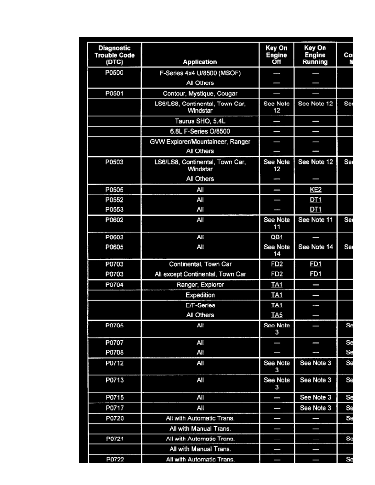
For diagnosis of P0721 refer to chart
Page 3

> A L L Diagnostic Trouble Codes ( DTC ) > Codes by Number > P0700-P07ZZ > P0720 - P0724, ( P0721 P0722 P0723 0720 0721 0722 0723 0724 ) > System Information
> System Diagnosis > P0721 ( P 0721 ) > Page 9
Escort L4-122 2.0L SOHC VIN P SFI (1999)
Page 4
Page 5
> A L L Diagnostic Trouble Codes ( DTC ) > Codes by Number > P0700-P07ZZ > P0720 - P0724, ( P0721 P0722 P0723 0720 0721 0722 0723 0724 ) > System Information
> System Diagnosis > P0721 ( P 0721 ) > Page 10
Escort L4-122 2.0L SOHC VIN P SFI (1999)
For complete Engine Control diagnostic information, See: Powertrain Management/Computers and Control Systems/Testing and Inspection
Automatic Transmission (A.T.)
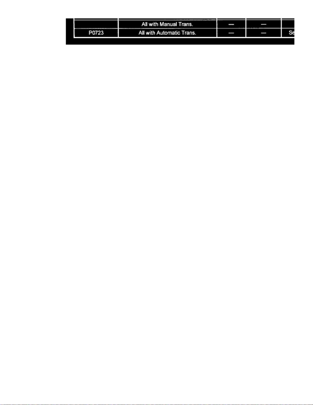
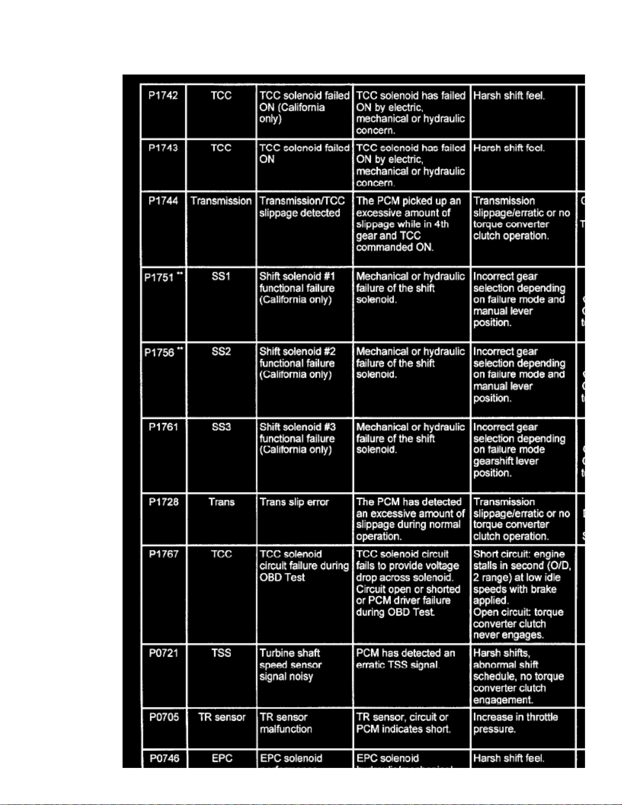
For diagnosis of P0721 refer to chart
Page 6
Page 7

For complete Transmission Control diagnostic information, See: Powertrain Management/Transmission Control Systems/Testing and Inspection
For complete Engine Control diagnostic information, See: Powertrain Management/Computers and Control Systems/Testing and Inspection
Page 8
> A L L Diagnostic Trouble Codes ( DTC ) > Codes by Number > P1400-P14ZZ > P1460 - P1464, ( P1461 P1462 P1463 1460 1461 1462 1463 1464 ) > System Information > System Diagnosis > P1464
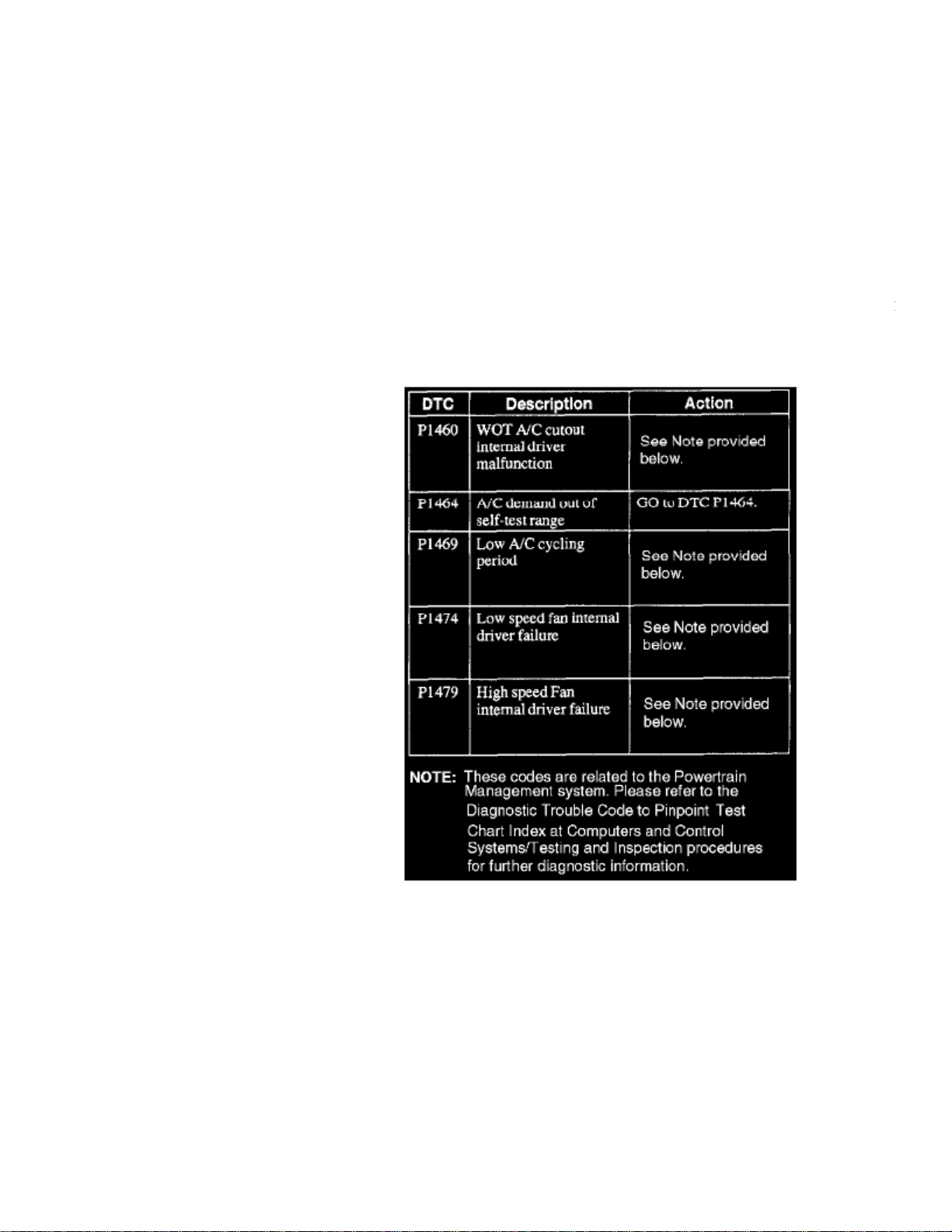
P1460 - P1464: Testing and InspectionP1464
For diagnosis of refer to the system experiencing the problem.P1464
Computers and Control Systems or Transmission Control System
Refer to pinpoint test X124. See: Powertrain Management/Computers and Control Systems/Testing and Inspection/Pinpoint Tests/X - ConstantControl Relay Module (CCRM)/X120 - X124
For complete Engine Control diagnostic information, See: Powertrain Management/Computers and Control Systems/Testing and Inspection
Heating and Air Conditioning
For complete Heating and Air Conditioning diagnostic information, See: Heating and Air Conditioning/Testing and Inspection
Page 9

Page 10

> Relays and Modules > Relays and Modules - Accessories and Optional Equipment > Alarm Module, (Vehicle Antitheft) > Component Information > Specifications
Alarm Module: Specifications
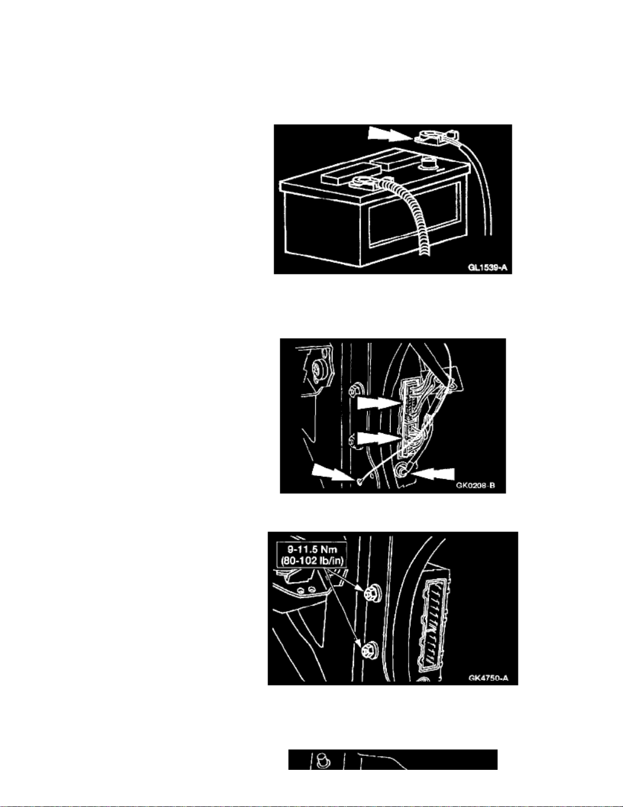
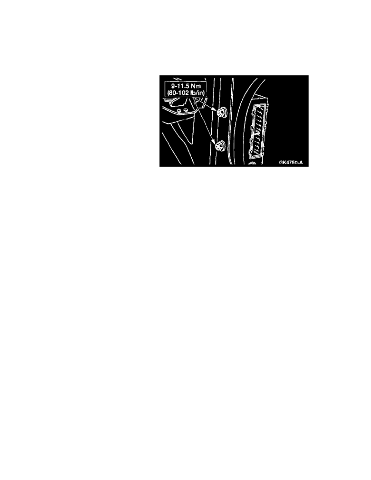
RAP Module Nuts 9-11.5 Nm
Page 11

Page 12
> Relays and Modules > Relays and Modules - Accessories and Optional Equipment > Alarm Module, (Vehicle Antitheft) > Component Information > Specifications > Page 21
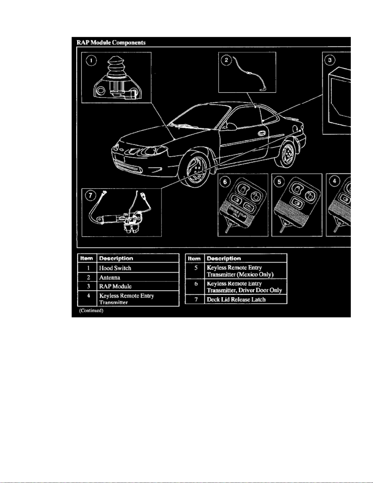
RAP Module Components
Page 13

Page 14
> Relays and Modules > Relays and Modules - Accessories and Optional Equipment > Alarm Module, (Vehicle Antitheft) > Component Information > Specifications > Page 22
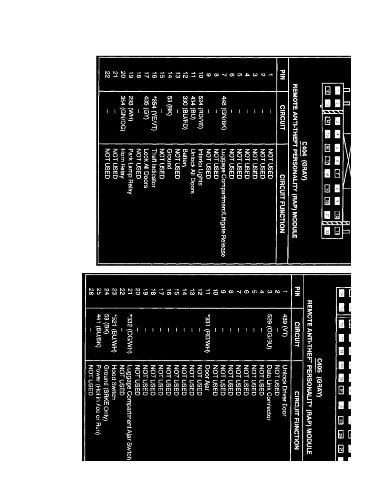
Alarm Module: Diagrams
Page 15

Page 16
> Relays and Modules > Relays and Modules - Accessories and Optional Equipment > Alarm Module, (Vehicle Antitheft) > Component Information > Specifications > Page 23
Alarm Module: Description and Operation
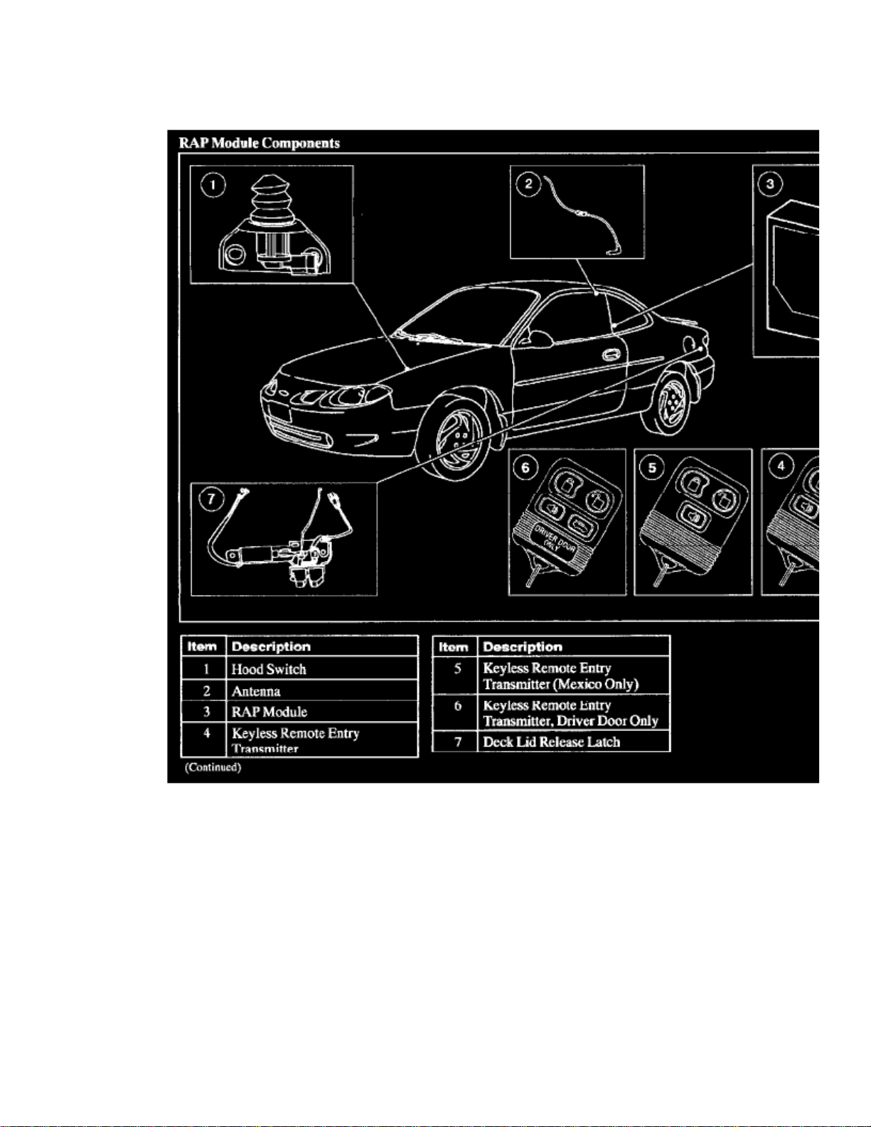
RAP Module Components
(RAP)
The remote Anti-theft Personality module uses a keyless remote entry transmitter to lock/unlock the door(s) and arm/disarm anti-theft (ifequipped). Three levels of the RAP module are available:
^ Driver door remote system with anti-theft.
^ Two-door remote entry with anti-theft.
^ Anti-theft only (available only in Mexico).
(TIC)
All levels of the RAP module use a keyless remote entry transmitter that emits a radio frequency called a Transmitter Identification Code . TICscan be retrieved using New Generation STAR (NGS) Tester.
Driver Door Remote
Page 17

> Relays and Modules > Relays and Modules - Accessories and Optional Equipment > Alarm Module, (Vehicle Antitheft) > Component Information > Specifications > Page
24
Escort L4-122 2.0L SOHC VIN P SFI (1999)
The driver door remote level RAP module uses the keyless remote entry transmitter to:^Lock/unlock the driver door.
^ Release the deck lid.
^ Activate/deactivate the panic alarm.
^ Activate/deactivate the dome courtesy lamp.
^Anti-Theft Only (Available only in Mexico)
Activate panic alarm.
^ Arm/disarm anti-theft.
Two-Door Remote Entry With Anti-Theft
The two-door remote entry level RAP module uses the keyless remote entry transmitter to:^
Lock/unlock the driver door or passenger door.
^ Release the deck lid.
Page 18

^ Activate/deactivate the dome courtesy lamp.
^ Arm/disarm anti-theft.
^ Activate/deactivate the panic alarm.
Page 19

Page 20
> Relays and Modules > Relays and Modules - Accessories and Optional Equipment > Alarm Module, (Vehicle Antitheft) > Component Information > Service and Repair > Sedan
Alarm Module: Service and RepairSedan
REMOVAL
1. Disconnect the battery ground cable.2. Remove the quarter trim pane.
^ Remove the RH trim panel.
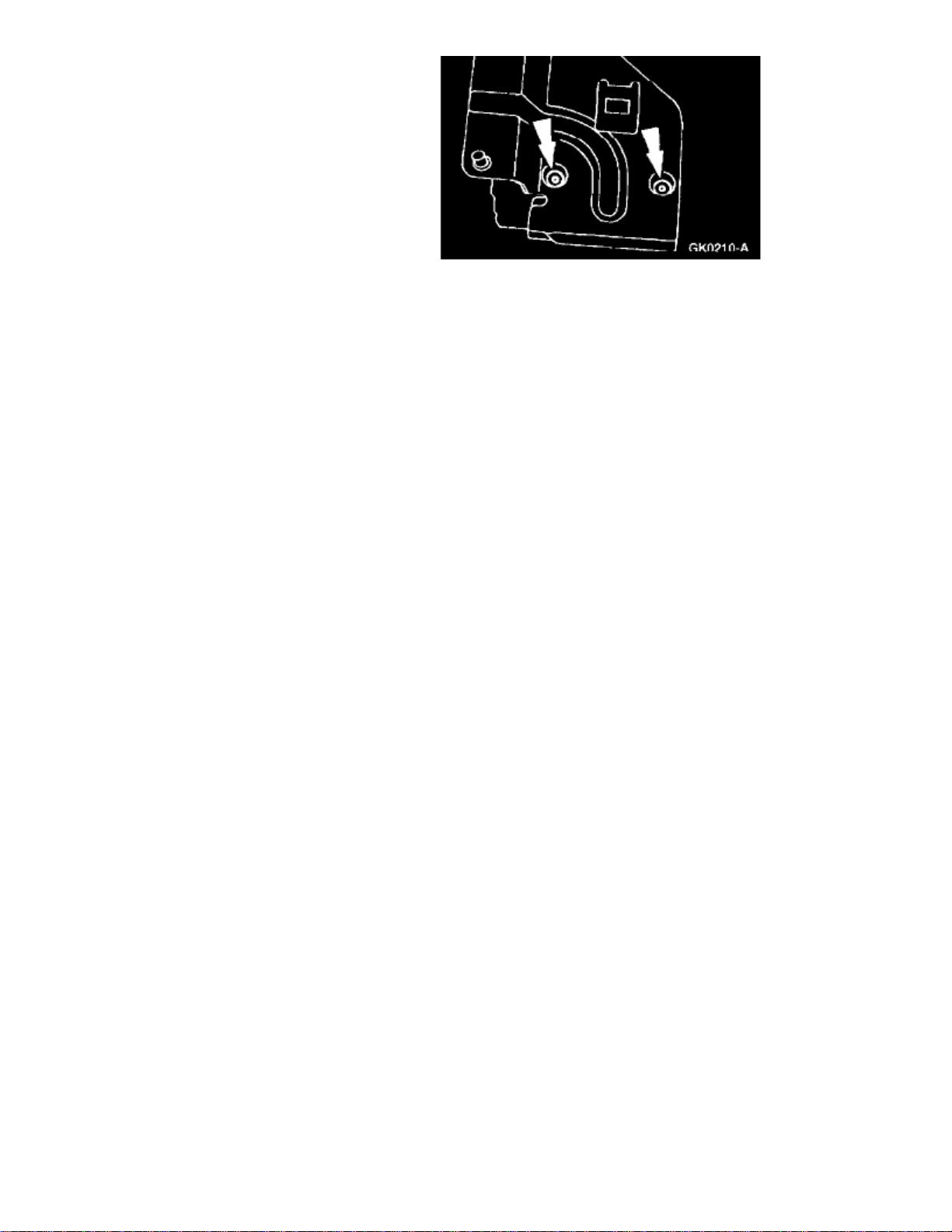
3. Disconnect the two electrical connectors, the ground strap from the sheet metal and the remote Anti-theft Personality module antenna.(RAP)
4. Remove the nuts and the RAP module.
Electronic modules are sensitive to static electrical charges. If exposed to these charges, damage may result.CAUTION:
Page 21
> Relays and Modules > Relays and Modules - Accessories and Optional Equipment > Alarm Module, (Vehicle Antitheft) > Component Information > Service and Repair >
Sedan > Page 27
Escort L4-122 2.0L SOHC VIN P SFI (1999)
Page 22
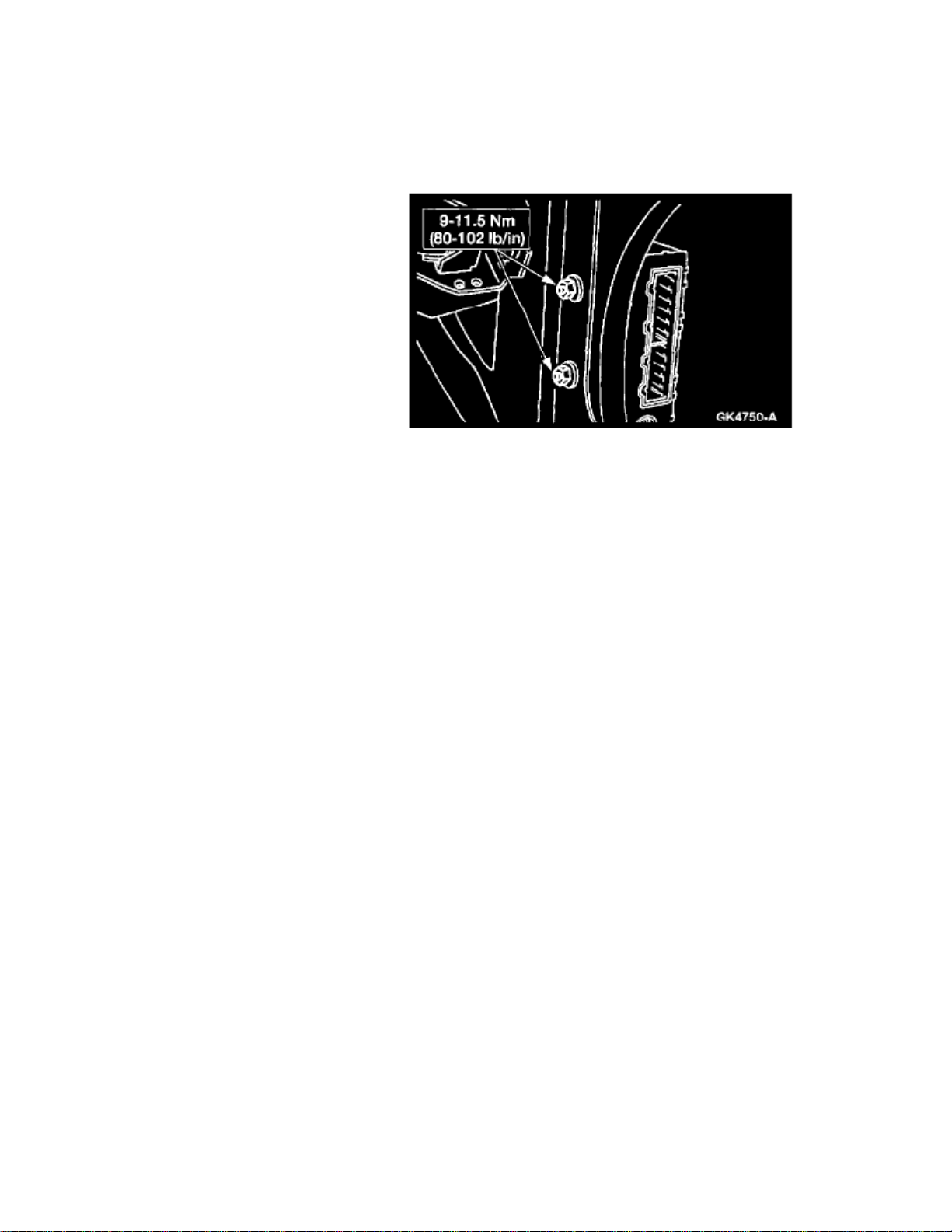
5. Lift the two tabs and remove the RAP module from the bracket.
INSTALLATION
1. To install, reverse the removal procedure.
NOTE:
When the battery is disconnected and reconnected, some abnormal drive symptoms may occur while the vehicle relearns its adaptivestrategy. The vehicle may need to be driven or more to relearn the strategy.16 km (10 mi)
Page 23

Page 24
> Relays and Modules > Relays and Modules - Accessories and Optional Equipment > Alarm Module, (Vehicle Antitheft) > Component Information > Service and Repair > Sedan > Page 28
Alarm Module: Service and RepairWagon
REMOVAL
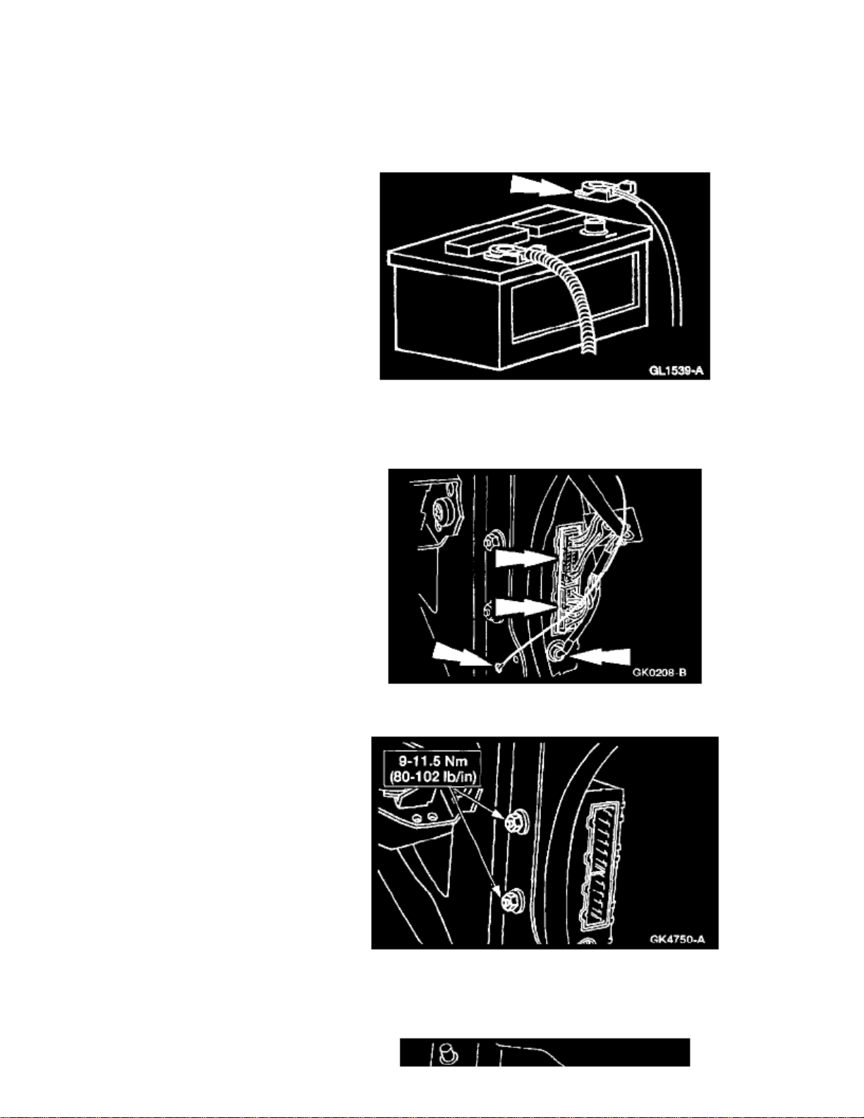
1. Disconnect the battery ground cable.2. Remove the quarter trim pane.
^ Remove the LH trim panel.
3. Disconnect the two electrical connectors, the ground strap from the sheet metal and the remote Anti-theft Personality module antenna.(RAP)
4. Remove the nuts and the RAP module.
Electronic modules are sensitive to static electrical charges. If exposed to these charges, damage may result.CAUTION:
Page 25
> Relays and Modules > Relays and Modules - Accessories and Optional Equipment > Alarm Module, (Vehicle Antitheft) > Component Information > Service and Repair >
Sedan > Page 29
Escort L4-122 2.0L SOHC VIN P SFI (1999)
Page 26
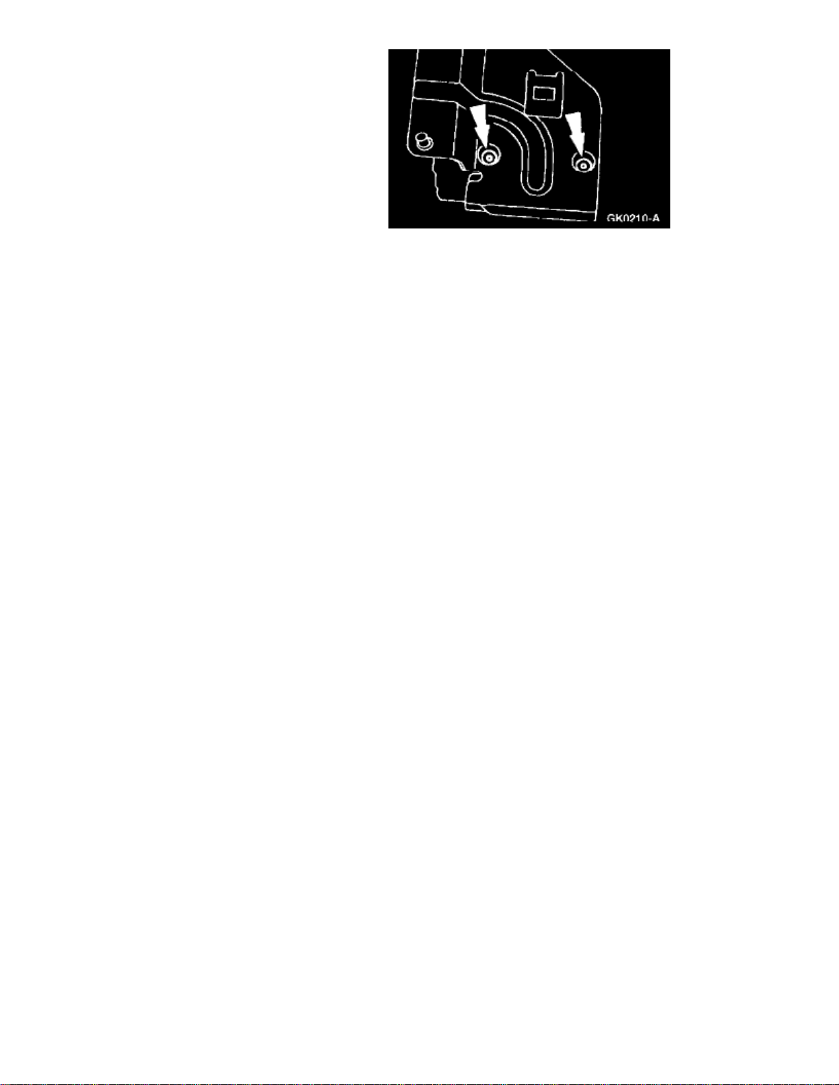
5. Lift the two tabs and remove the RAP module from the bracket.
INSTALLATION
1. To install, reverse the removal procedure.
NOTE:
When the battery is disconnected and reconnected, some abnormal drive symptoms may occur while the vehicle relearns its adaptivestrategy. The vehicle may need to be driven or more to relearn the strategy.16 km (10 mi)
Page 27

Page 28
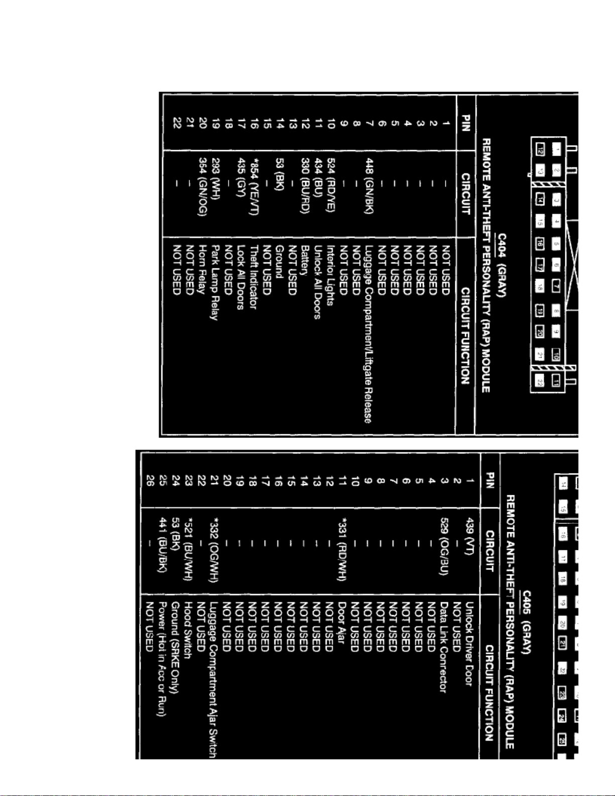
> Relays and Modules > Relays and Modules - Accessories and Optional Equipment > Keyless Entry Module > Component Information > Diagrams
Keyless Entry Module: Diagrams
Page 29

Page 30

> Relays and Modules > Relays and Modules - Accessories and Optional Equipment > Keyless Entry Module > Component Information > Diagrams > Page 33
Keyless Entry Module: Service and Repair
NOTE: (RAP)
After replacing the Remote Anti-theft Personality module it is necessary to reconfigure the module using the New Generation STAR Tester.(NGS)
Page 31

Page 32
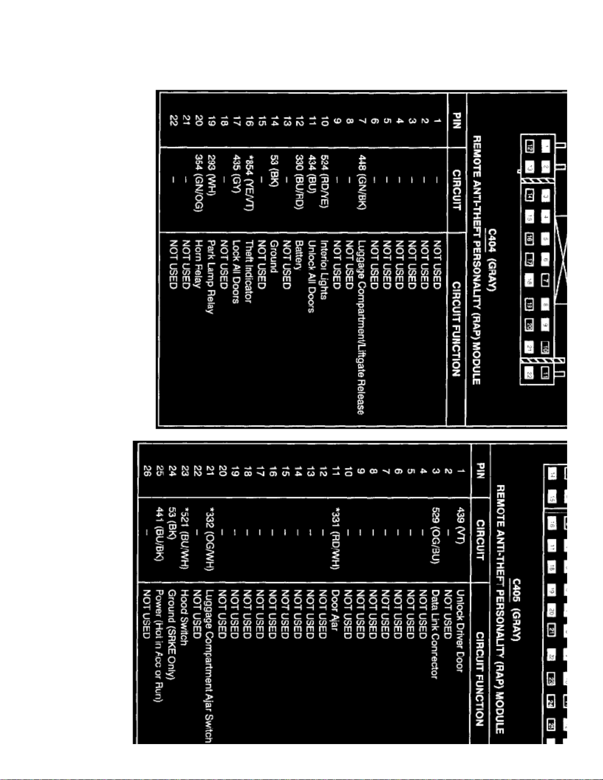
> Relays and Modules > Relays and Modules - Body and Frame > Keyless Entry Module > Component Information > Diagrams
Keyless Entry Module: Diagrams
Page 33

Page 34

> Relays and Modules > Relays and Modules - Body and Frame > Keyless Entry Module > Component Information > Diagrams > Page 38
Keyless Entry Module: Service and Repair
NOTE: (RAP)
After replacing the Remote Anti-theft Personality module it is necessary to reconfigure the module using the New Generation STAR Tester.(NGS)
Page 35

Page 36
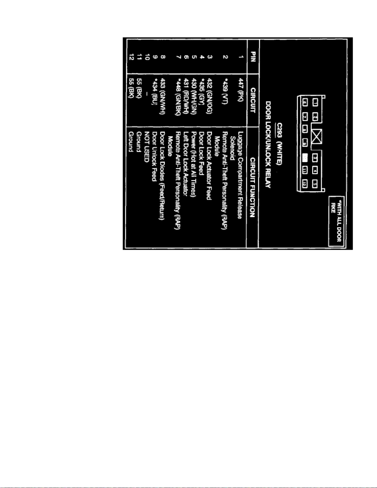
> Relays and Modules > Relays and Modules - Body and Frame > Power Door Lock Relay > Component Information > Diagrams
Page 37

Page 38
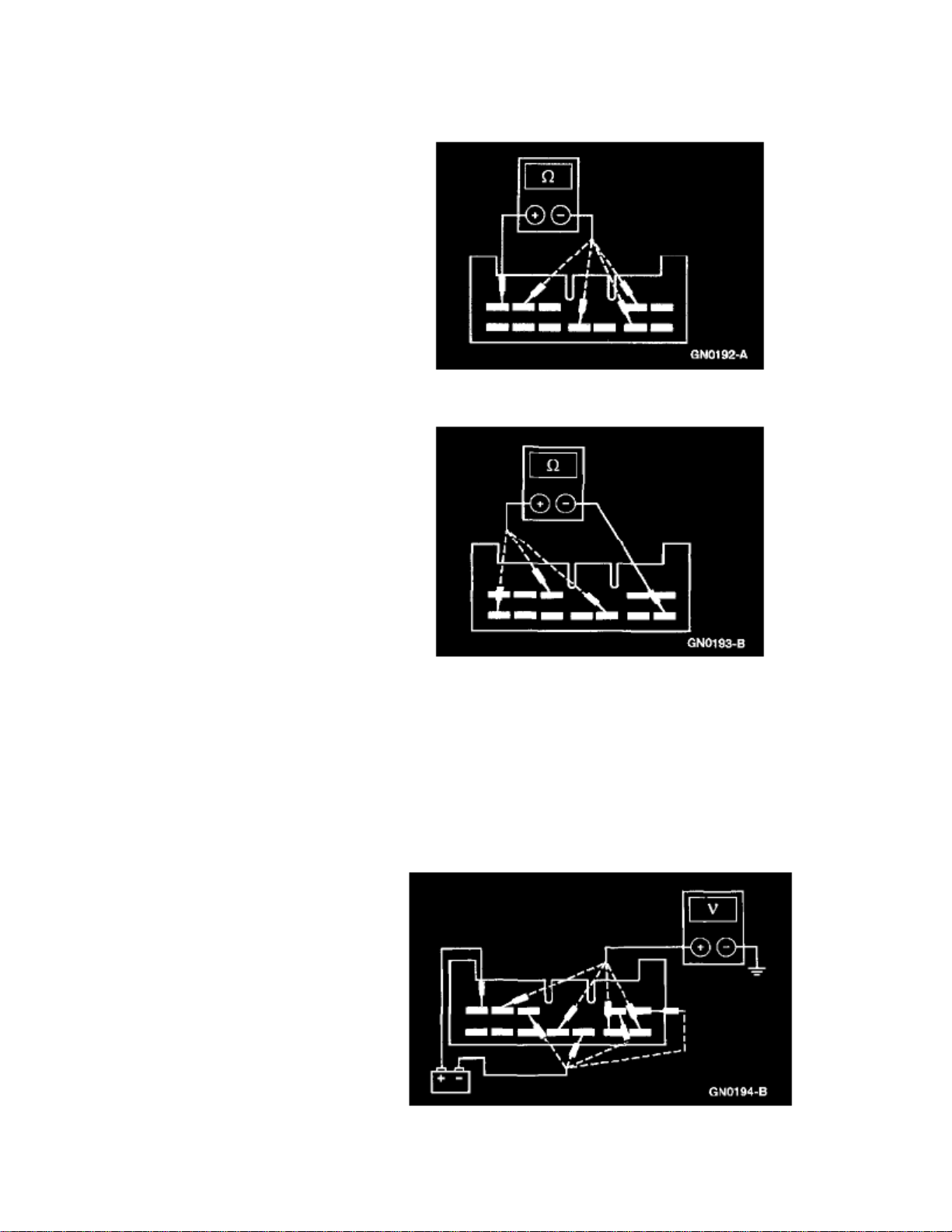
> Relays and Modules > Relays and Modules - Body and Frame > Power Door Lock Relay > Component Information > Diagrams > Page 42
Power Door Lock Relay: Testing and Inspection
1. Remove and disconnect the power door lock relay.
2. Measure resistance between the power door lock relay, terminal 5, and the power door lock relay terminals.
Terminal Resistance
2, 4, 7, 9
Between 150-185 Ohms
3. Measure resistance between the power door lock relay, terminal 6, and the power door lock relay terminals.
Terminal Resistance
3, 8, 12
Less than 5 Ohms
4. If the power door lock switch fails any of the above tests, install a new one. Otherwise, proceed to the next step.
Page 39

> Relays and Modules > Relays and Modules - Body and Frame > Power Door Lock Relay > Component Information > Diagrams > Page 43
Escort L4-122 2.0L SOHC VIN P SFI (1999)
Page 40
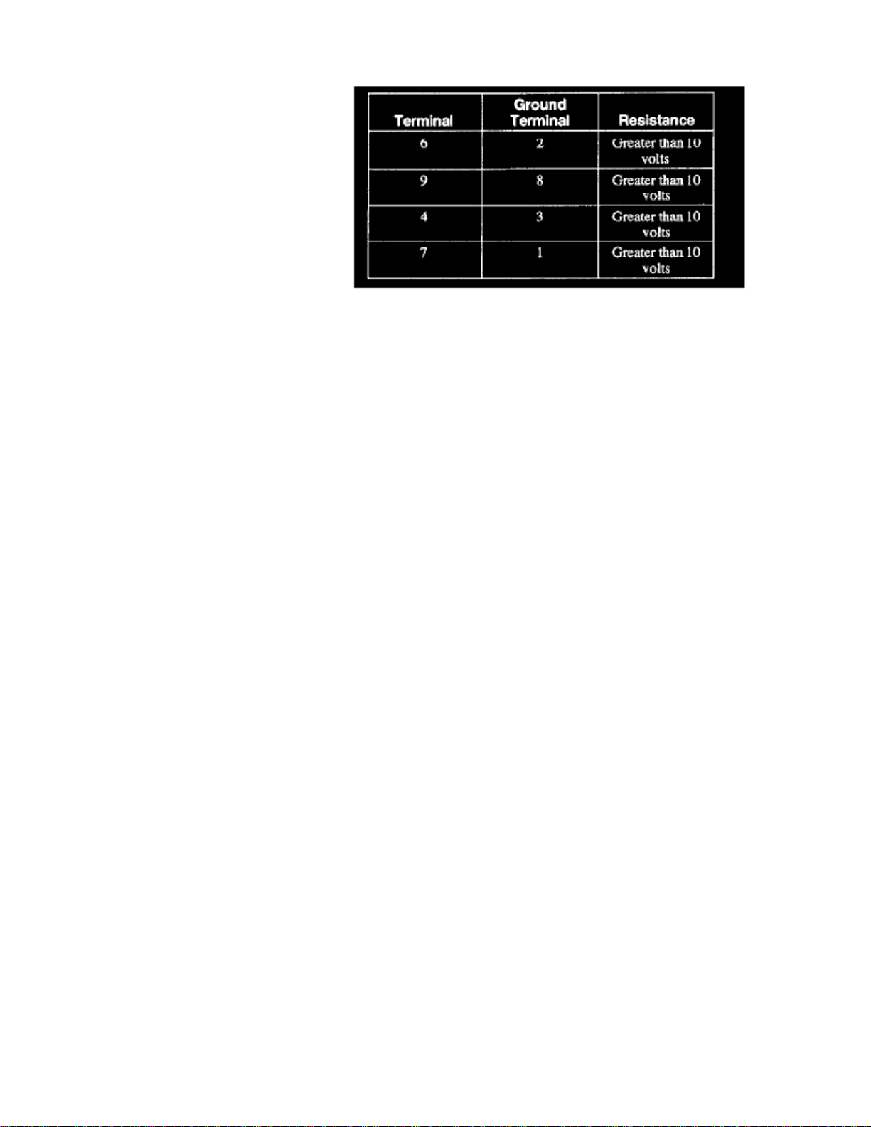
5. Apply to the power door lock relay terminal 5.12 volts
Measure the voltage between the power door lock relay terminals, and ground, while grounding the terminals as indicated in the illustration.
6. If the power door lock switch fails any of the above tests, install a new one.
Page 41

Page 42
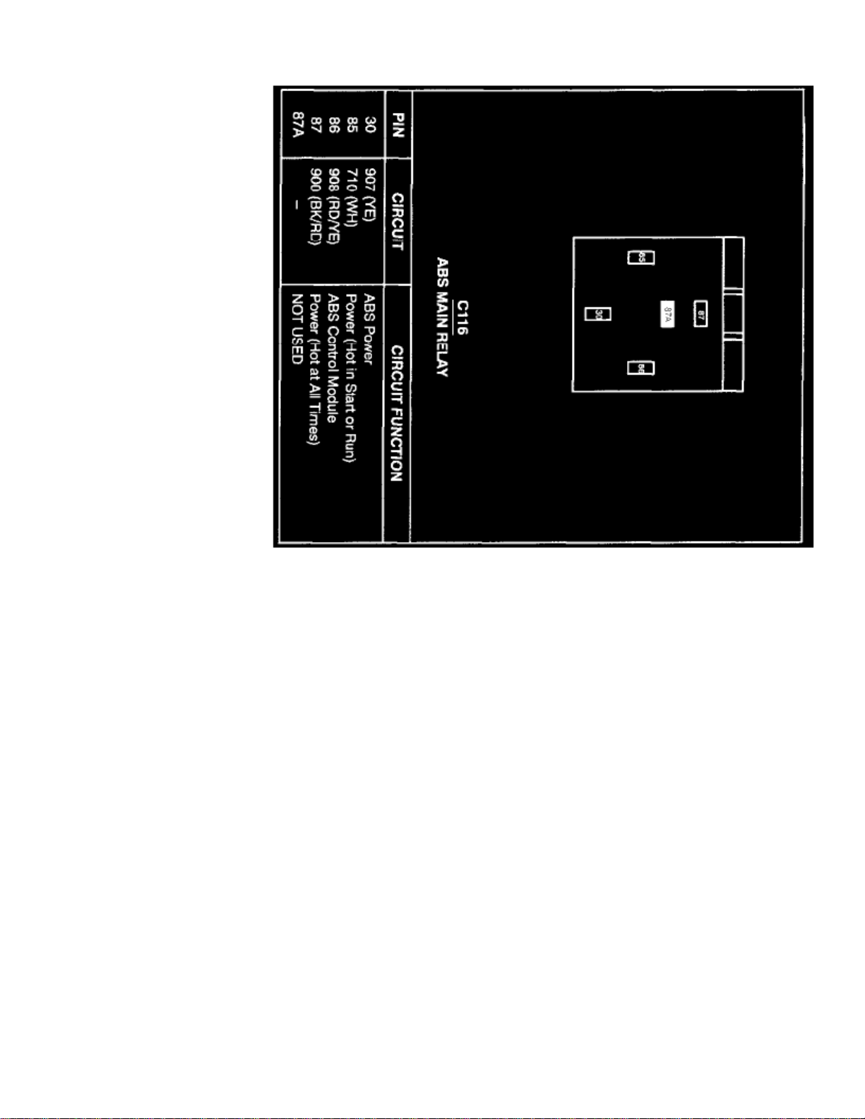
> Relays and Modules > Relays and Modules - Brakes and Traction Control > ABS Main Relay > Component Information > Diagrams
Page 43

Page 44
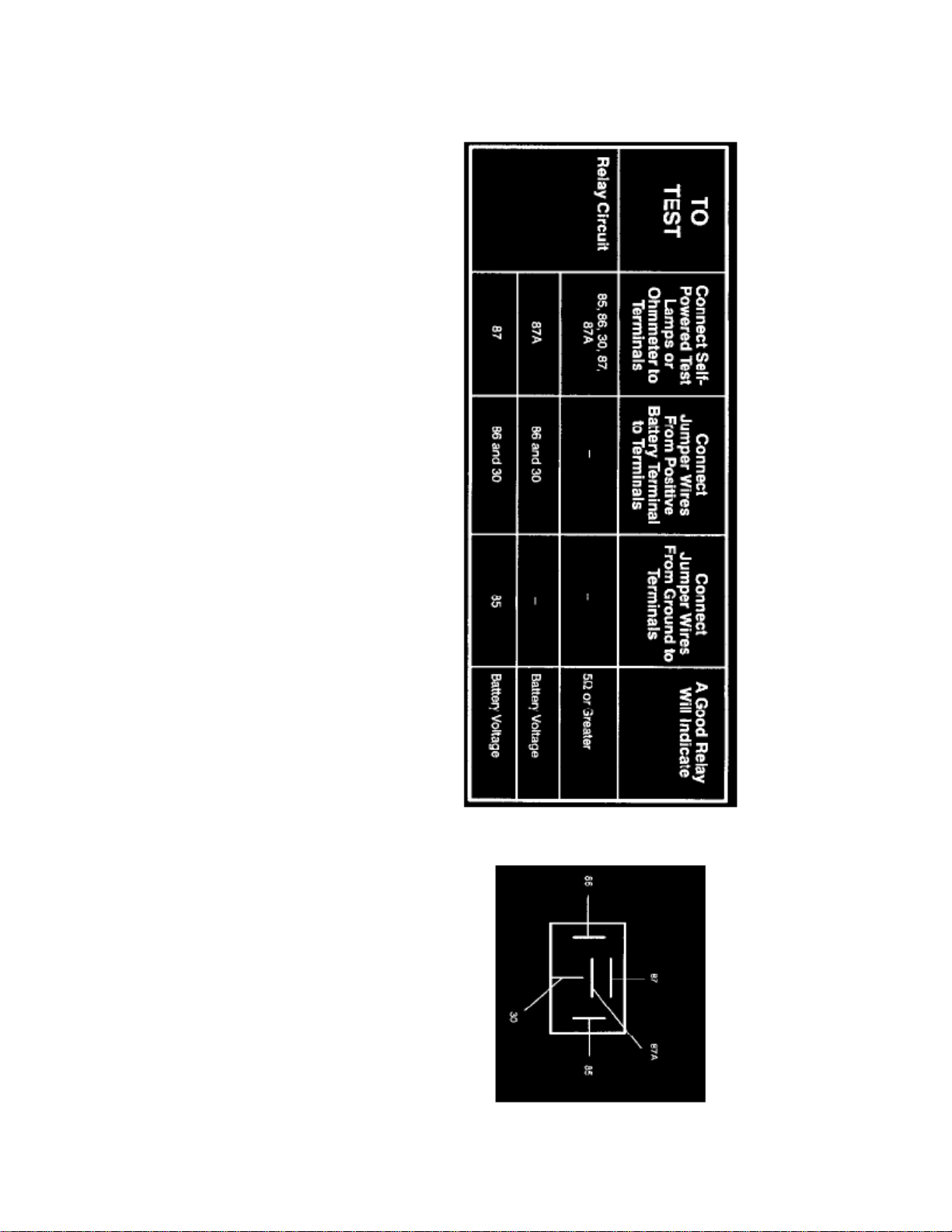
> Relays and Modules > Relays and Modules - Brakes and Traction Control > ABS Main Relay > Component Information > Diagrams > Page 48
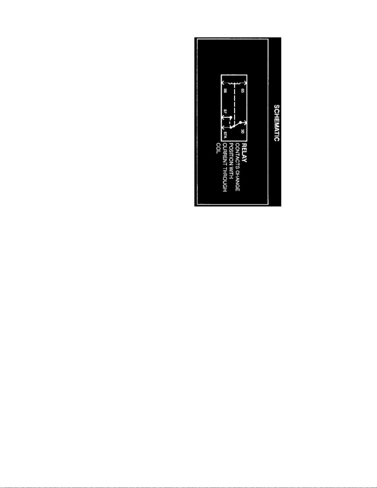
ABS Main Relay: Testing and Inspection
Component Testing Procedure
Terminals
Page 45

> Relays and Modules > Relays and Modules - Brakes and Traction Control > ABS Main Relay > Component Information > Diagrams > Page 49
Escort L4-122 2.0L SOHC VIN P SFI (1999)
Page 46
Page 47

Page 48

> Relays and Modules > Relays and Modules - Brakes and Traction Control > Electronic Brake Control Module > Component Information > Specifications
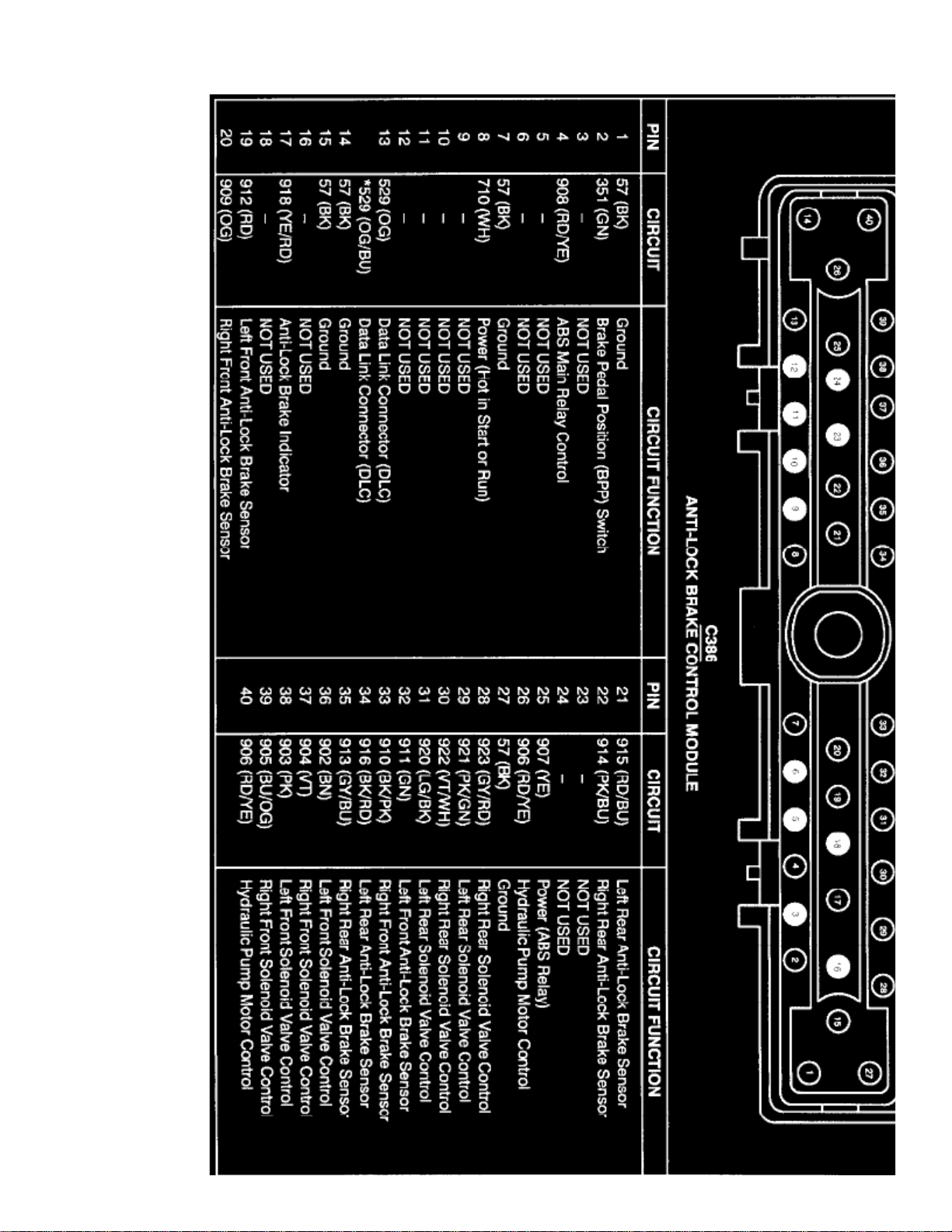
Electronic Brake Control Module: Specifications
Retaining Screws .......................................................................................................................................................................... 7-10 Nm (61-86 inch lbs.)Electrical Connector ....................................................................................................................................................................... 6-7 Nm (53-62 inch lbs.)
Page 49

Page 50
> Relays and Modules > Relays and Modules - Brakes and Traction Control > Electronic Brake Control Module > Component Information > Specifications > Page 53
Page 51

Diagram 42-4
Page 52

> Relays and Modules > Relays and Modules - Brakes and Traction Control > Electronic Brake Control Module > Component Information > Specifications > Page 54
Electronic Brake Control Module: Description and Operation
The anti-lock brake control module is a non-repairable, on-board diagnostic unit consisting of one microprocessor and the necessary circuitry for itsoperation. The two primary functions of the anti-lock brake control module are to control the HCU during ABS operation and to monitor the systemduring normal driving, as well as during anti-lock braking.
Under normal braking conditions, the microprocessor produces short test pulses to check the electrical system without any mechanical reaction. Theanti-lock brake control module continuously monitors the speed of each wheel to determine if any wheel is beginning to lock. When a wheel lockingtendency is detected, the anti-lock brake control module signals the appropriate isolation valve and/or dump valve in the HCU to open or close as wellas the pump motor to turn on and return brake fluid back to the foundation braking system.
(DTC)
Most faults that occur in the ABS will be stored as a Diagnostic Trouble Code in the anti-lock brake control module. Once a DTC is stored, itwill be retained by the anti-lock brake control module even with the key in the OFF position. DTCs can be retrieved by following the on-boarddiagnostics procedures.
Page 53

Page 54
> Relays and Modules > Relays and Modules - Brakes and Traction Control > Electronic Brake Control Module > Component Information > Specifications > Page 55
Electronic Brake Control Module: Service and Repair
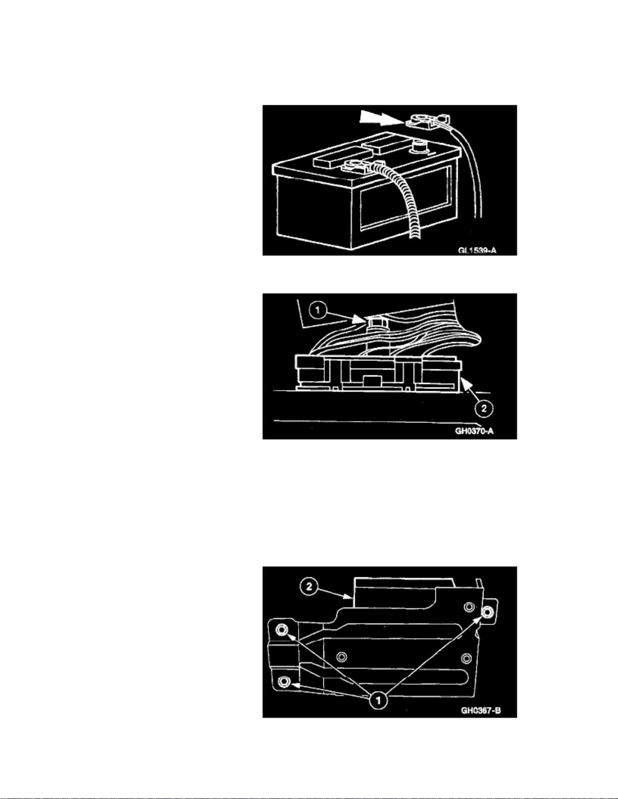
Removal
1. Disconnect the battery ground cable.
your body when handling electronic components.
The anti-lock brake control module is located under the passenger seat.NOTE:
Disconnect the anti-lock brake control module electrical connector.1
Loosen the bolt.
2 Remove the electrical connector.
3. Remove the anti-lock brake control module.
Page 55

> Relays and Modules > Relays and Modules - Brakes and Traction Control > Electronic Brake Control Module > Component Information > Specifications > Page 56
Escort L4-122 2.0L SOHC VIN P SFI (1999)
1 Remove the bolts.
2 Remove the anti-lock brake control module.
Installation
NOTE:
When the battery is disconnected and reconnected, some abnormal drive symptoms may occur while the vehicle relearns its adaptive strategy.The vehicle may need to be drive or more to relearn its strategy.16 km (10 mi)
Page 56
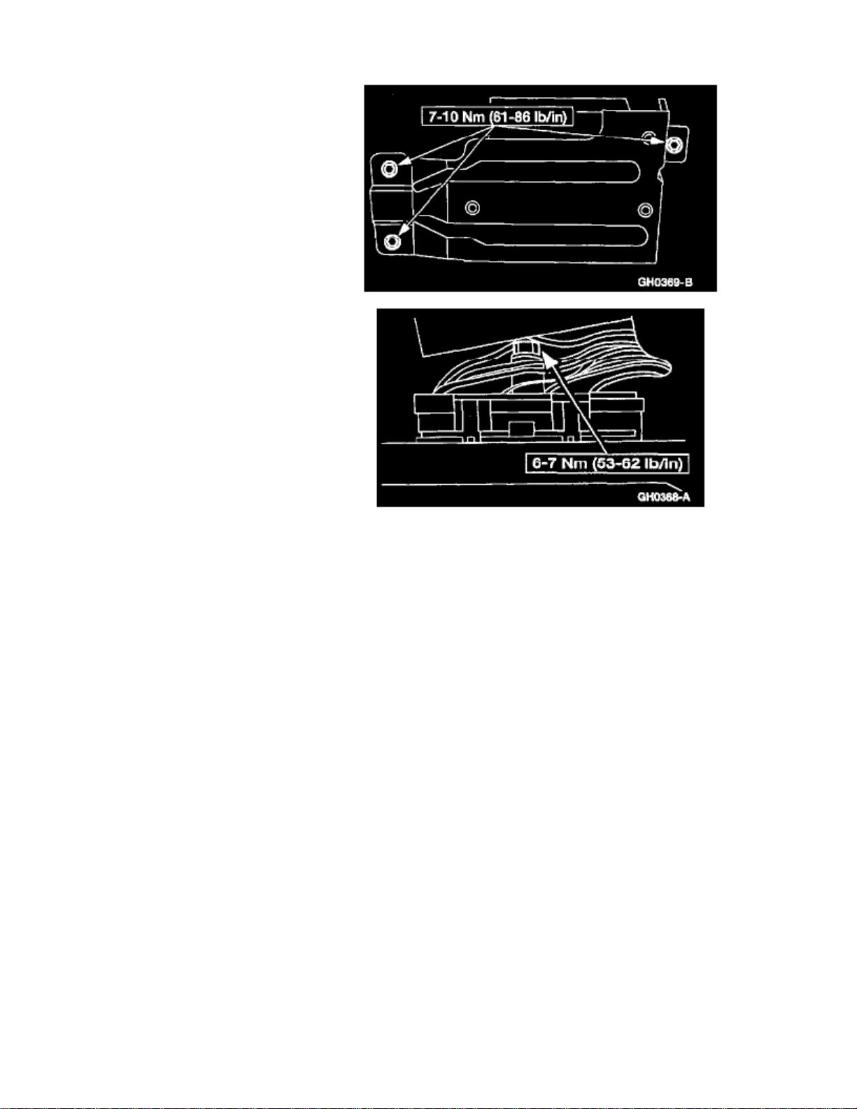
1. To install, reverse the removal procedure.
Page 57

Page 58

> Relays and Modules > Relays and Modules - Cooling System > Radiator Cooling Fan Motor Relay > Component Information > Specifications
Radiator Cooling Fan Motor Relay: Specifications
Constant Control Relay Module Bolts ........................................................................................................................................... 8-11 Nm (71-97 In Lbs).
Page 59

Page 60
> Relays and Modules > Relays and Modules - Cooling System > Radiator Cooling Fan Motor Relay > Component Information > Specifications > Page 61
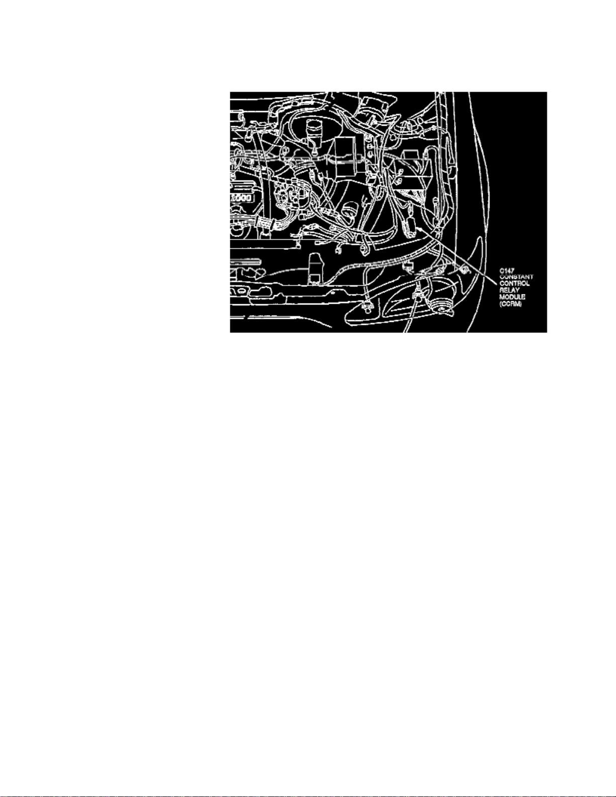
Radiator Cooling Fan Motor Relay: Locations
Constant Control Relay Module (CCRM)
The Constant Control Relay Module is located at the LH front of the engine.
Page 61

Page 62
> Relays and Modules > Relays and Modules - Cooling System > Radiator Cooling Fan Motor Relay > Component Information > Diagrams > Diagram Information and Instructions
Radiator Cooling Fan Motor Relay: Diagram Information and Instructions
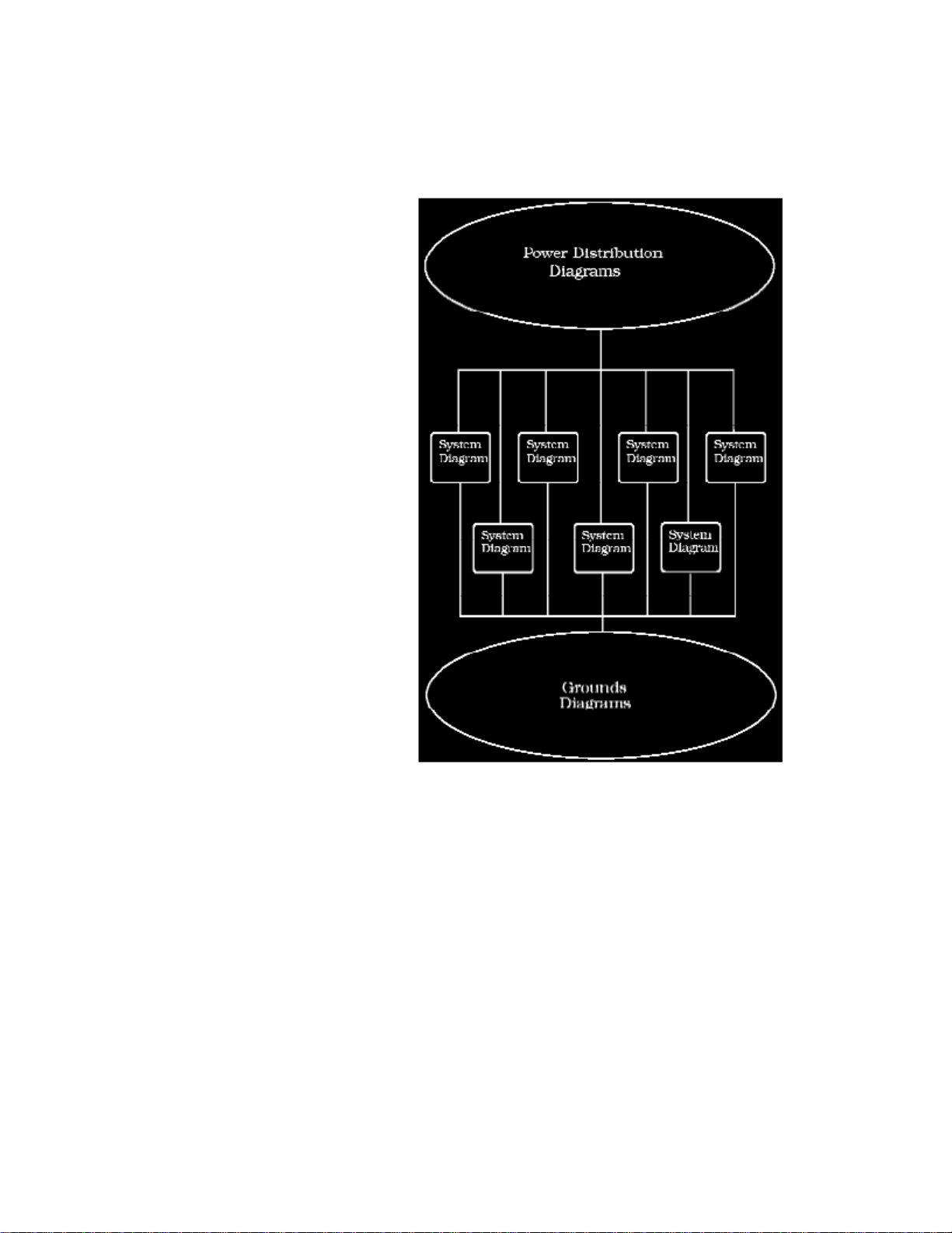
How to Find and Use These Diagrams
Diagrams are presented in three main categories:
- Power Distribution Diagrams
- System Diagrams
- Grounds Diagrams
Page 63

> Relays and Modules > Relays and Modules - Cooling System > Radiator Cooling Fan Motor Relay > Component Information > Diagrams > Diagram Information and
Instructions > Page 64
Escort L4-122 2.0L SOHC VIN P SFI (1999)
Page 64
Page 65

> Relays and Modules > Relays and Modules - Cooling System > Radiator Cooling Fan Motor Relay > Component Information > Diagrams > Diagram Information and
Instructions > Page 65
Escort L4-122 2.0L SOHC VIN P SFI (1999)
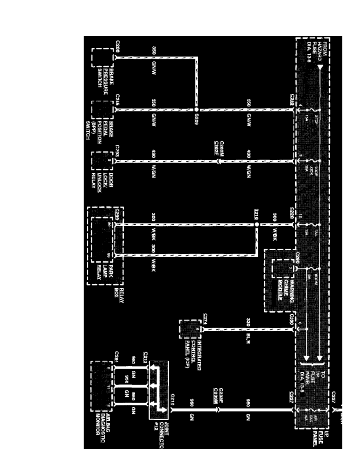
Diagram 13-7 (Sample Power Distribution Diagram Page)
Power Distribution Diagrams
Provide the circuit details of how the system diagrams are powered. The power distribution source is shown at the top of a diagram page. All wires,connectors, and splices are shown in the same manner that the current flows, ending at the component/system being powered near the bottom of adiagram page. Circuits that go from one diagram page to another will be marked with large arrow heads indicating which diagram page the circuit wentto/came from.
The power distribution diagrams can be found at Starting and Charging/Power and Ground Distribution, or by following the hyperlinks at the top of the
Page 66
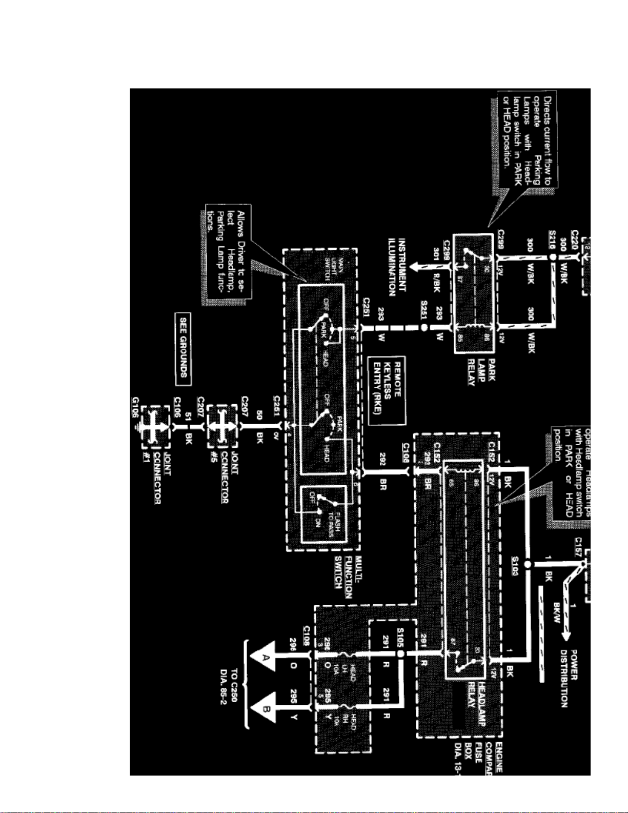
diagram pages within the system diagrams.
Page 67

> Relays and Modules > Relays and Modules - Cooling System > Radiator Cooling Fan Motor Relay > Component Information > Diagrams > Diagram Information and
Instructions > Page 66
Escort L4-122 2.0L SOHC VIN P SFI (1999)
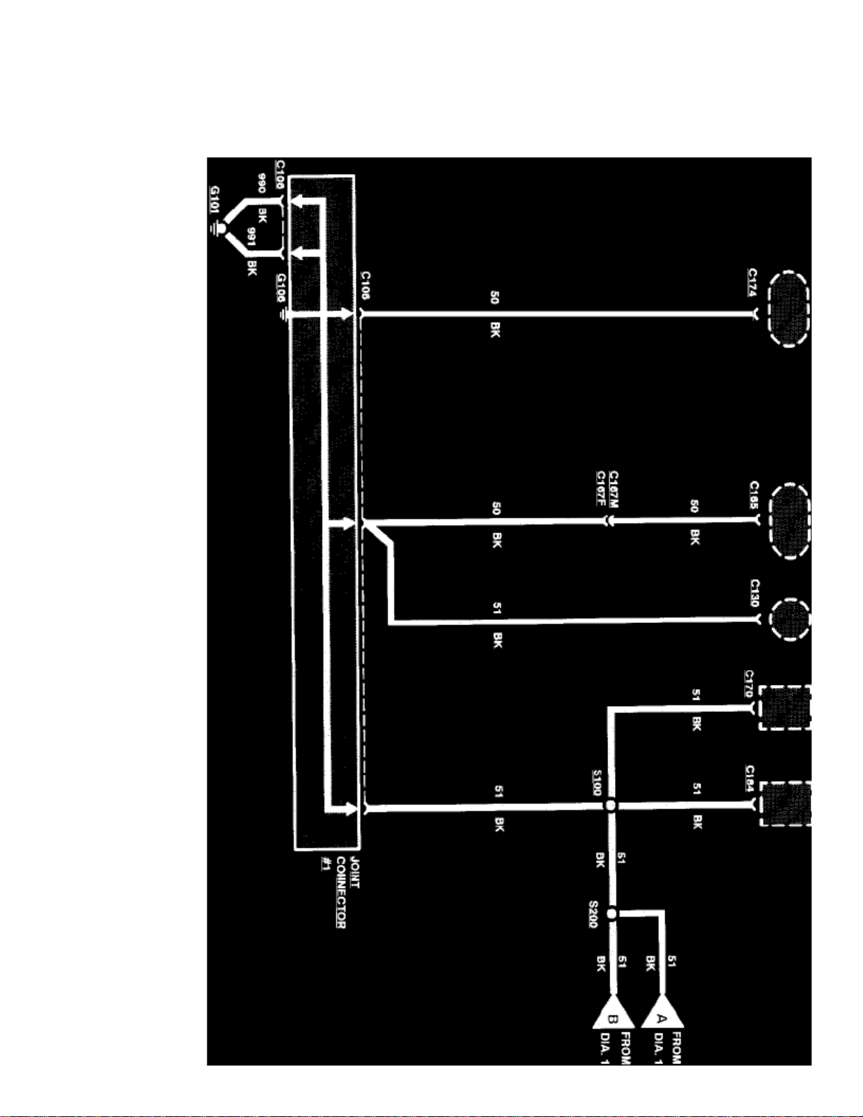
Diagram 85-1 (Sample System Diagram Page)
System Diagrams
Components that work together are shown together in a system/subsystem diagram or set of diagrams. The system feed (circuit breaker, fuse, etc.) isshown at the top of a diagram page. All wires, connectors, components, and splices are shown in the same manner that the current flows, ending at theground at the bottom of a diagram page. Circuits that go from one diagram page to another will be marked with large arrow heads indicating whichdiagram page the circuit went to/came from.
Page 68
Page 69

> Relays and Modules > Relays and Modules - Cooling System > Radiator Cooling Fan Motor Relay > Component Information > Diagrams > Diagram Information and
Instructions > Page 67
Escort L4-122 2.0L SOHC VIN P SFI (1999)
Diagram 10-1 (Sample Grounds Diagram Page)
Grounds Diagrams
Provide the circuit details of how the system diagrams are grounded. This information is useful for checking interconnections of the grounding circuits ofdifferent systems. The components/systems being grounded are shown at the top of a diagram page. All wires, connectors, and splices are shown in thesame manner that the current flows, ending at the ground at the bottom of a diagram page. Circuits that go from one diagram page to another will bemarked with large arrow heads indicating which diagram page the circuit went to/came from.
Page 70
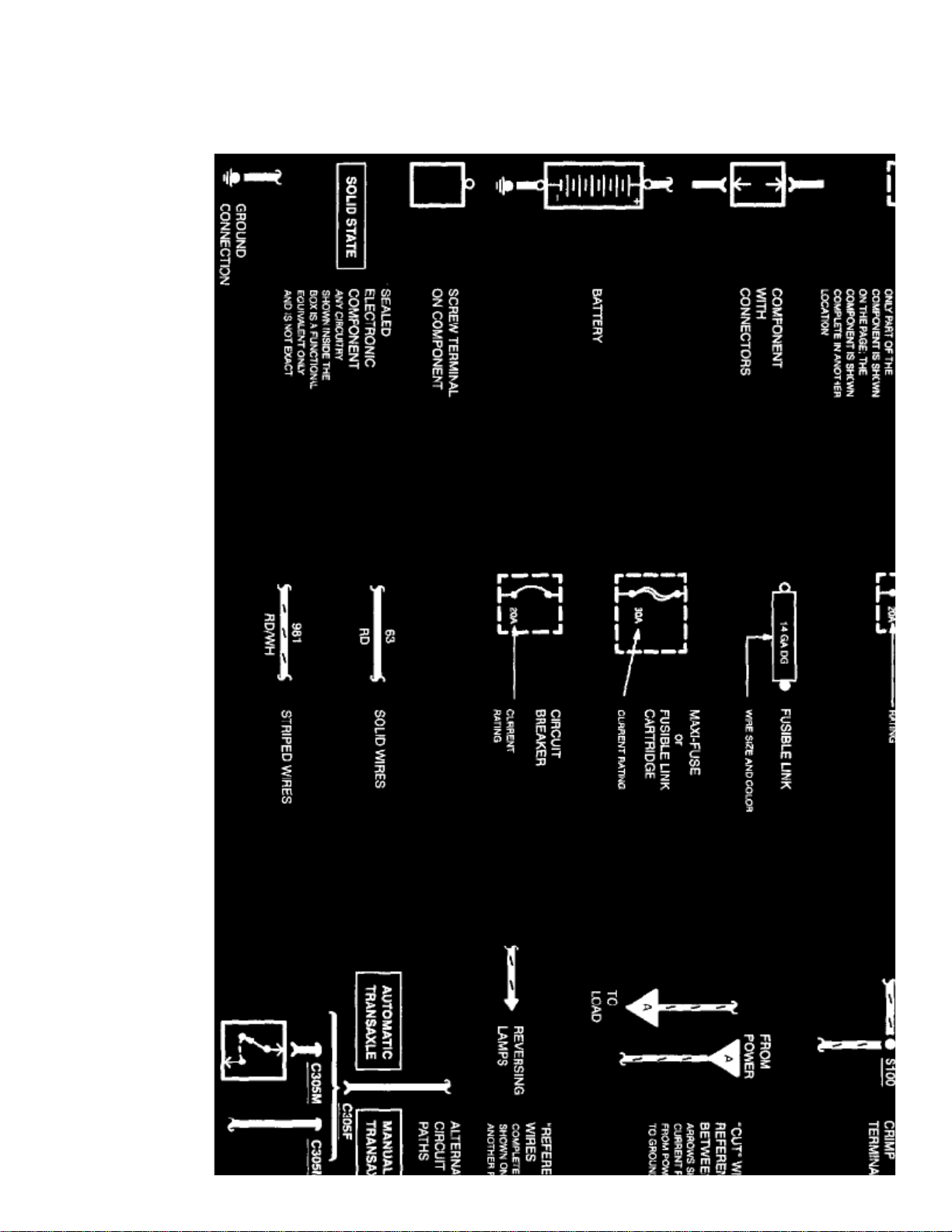
The grounds diagrams can be found at Starting and Charging/Power and Ground Distribution, or by following the hyperlinks at the bottom of thediagram pages within the system diagrams.
Page 71

> Relays and Modules > Relays and Modules - Cooling System > Radiator Cooling Fan Motor Relay > Component Information > Diagrams > Diagram Information and
Instructions > Page 68
Escort L4-122 2.0L SOHC VIN P SFI (1999)
Page 72
Page 73

> Relays and Modules > Relays and Modules - Cooling System > Radiator Cooling Fan Motor Relay > Component Information > Diagrams > Diagram Information and
Instructions > Page 69
Escort L4-122 2.0L SOHC VIN P SFI (1999)
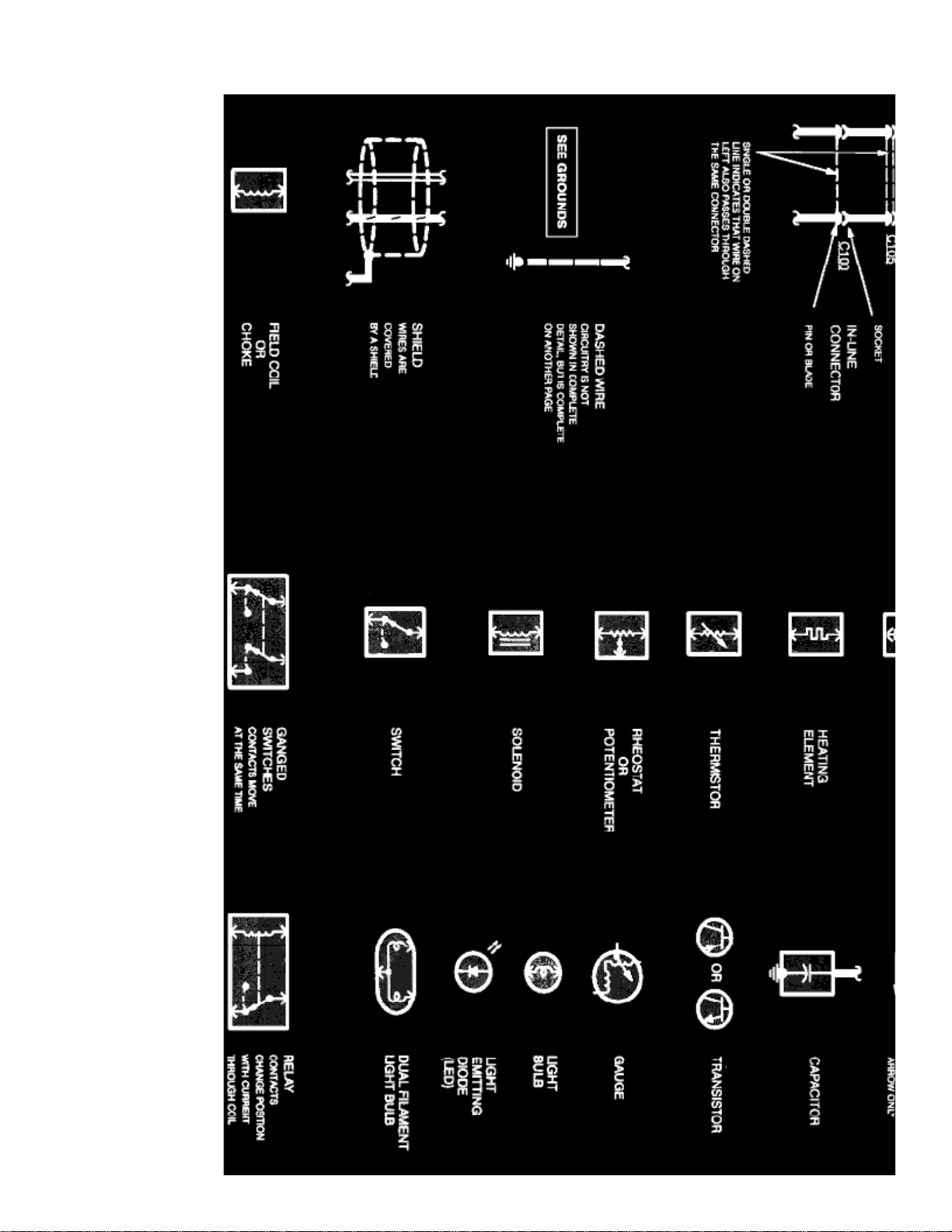
Electrical Symbols
Wire Color Code Identification
Wire and connector colors are listed as follows (standard Ford color abbreviations are used):
BUCOLOR ABBREVIATIONS
Blue NA Natural
BK Black OG Orange
Page 74

BN Brown PK Pink
DB Dark Blue VT Purple
DG Dark Green RD Red
GN Green SR Silver
GY Gray TN Tan
LB Light Blue WH White
LG Light Green YE Yellow
Note:
Whenever a wire is labeled with two colors, the first color listed is the basic color of the wire, and the second color listed is the stripemarking of the wire.
Page 75

Page 76

> Relays and Modules > Relays and Modules - Cooling System > Radiator Cooling Fan Motor Relay > Component Information > Diagrams > Diagram Information and Instructions> Page 70
Radiator Cooling Fan Motor Relay: Diagnostic Aids
HOW TO FIND ELECTRICAL CONCERNS
TROUBLESHOOTING STEPS
These six steps present an orderly method of troubleshooting.
Step 1. Verify the concern.
- Operate the complete system to check the accuracy and completeness of the customer's complaint.
Step 2. Narrow the concern.
- Using the wiring diagrams, narrow down the possible causes and locations of the concern to pinpoint the exact cause.
-
Read the description notes at the components and study the wiring schematic. You should then know enough about the circuit operation todetermine where to check for the trouble.
Step 3. Test the suspected cause.
- Use electrical test procedures to find the specific cause of the symptoms.
-
The component location reference bars and the pictures will help you find components. Component location information for connectors,diodes, resistors, splices and grounds can be found at Vehicle Locations. See: Locations
Step 4. Verify the cause.
-
Confirm that you have found the correct cause by connecting jumper wires and/or temporarily installing a known good component andoperating the circuit.
Step 5. Make the repair.
- Repair or replace the inoperative component.
Step 6. Verify the repair.
- Operate the system as in Step 1 and check that your repair has removed all symptoms without creating any new symptoms.
Some engine circuits may need special test equipment and special procedures. See Testing and Inspection for the specific component, system, orsub-system in question.
NOTE:
Most Ford testing and inspection procedures will be found at the system/sub-system level; only a few component tests are provided byOE.
TROUBLESHOOTING TOOLS
JUMPER WIRE
This is a test lead used to connect two points of a circuit. A Jumper Wire can bypass an open to complete a circuit.
WARNING: Never use a jumper wire across loads (motors,etc.) connected between hot and ground. This direct battery short may causeinjury or fire.
VOLTMETER
A DC Voltmeter measures circuit voltage. Connect negative (- or black) lead to ground, and positive (+ or red) lead to voltage measuring point.
OHMMETER
Page 77

> Relays and Modules > Relays and Modules - Cooling System > Radiator Cooling Fan Motor Relay > Component Information > Diagrams > Diagram Information and
Instructions > Page 71
Escort L4-122 2.0L SOHC VIN P SFI (1999)
An Ohmmeter shows the resistance between two connected points.
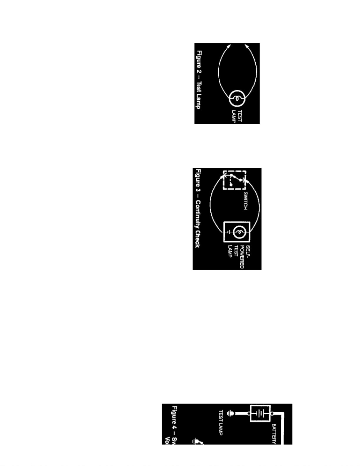
TEST LAMP
Page 78
12-volt
A Test Light is a bulb with two test leads. Voltage Check, Short Check.Uses:
SELF-POWERED TEST LAMP
CAUTION: When using a self -powered test lamp or ohmmeter; be sure power is off in circuit during testing. Hot circuits can causeequipment damage and false readings.
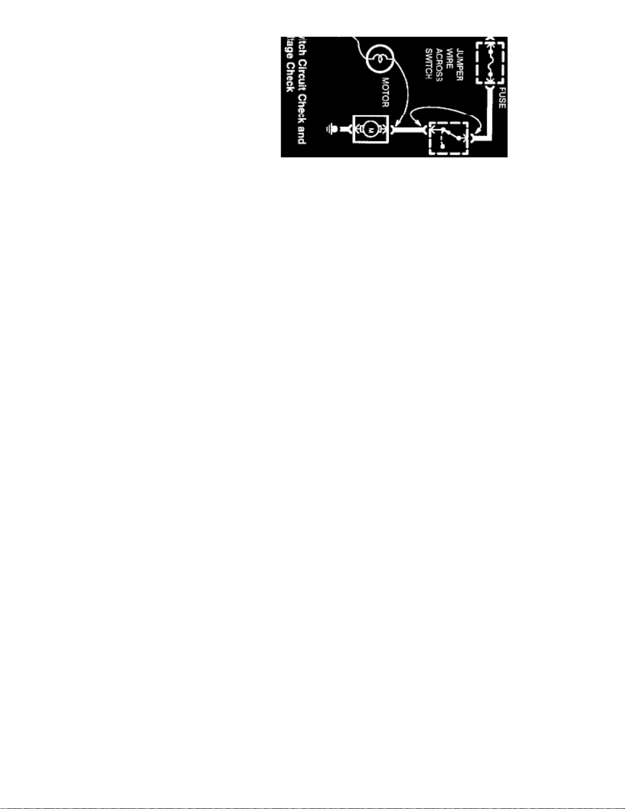
In an inoperative circuit with a switch in series with the load, jumper the terminals of the switch to power the load. If jumpering the terminalspowers the circuit, the switch is inoperative.
CONTINUITY CHECK(Locating open circuits)
Connect one lead of Self-Powered Test Lamp or Ohmmeter to each end of circuit. Lamp will glow if circuit is closed. Switches and fuses can bechecked in the same way.
VOLTAGE CHECK
Page 79
> Relays and Modules > Relays and Modules - Cooling System > Radiator Cooling Fan Motor Relay > Component Information > Diagrams > Diagram Information and
Instructions > Page 72
Escort L4-122 2.0L SOHC VIN P SFI (1999)
The Self-Powered Test Lamp is a bulb, battery and set of test leads wired in series. When connected to two points of a continuous circuit, the bulbglows. Continuity Check, Ground Check.Uses:
Connect one lead of test lamp to a known good ground or the negative (-) battery terminal. Test for voltage by touching the other lead to the test
Page 80
point. Bulb goes on when the test point has voltage.
SHORT CHECK
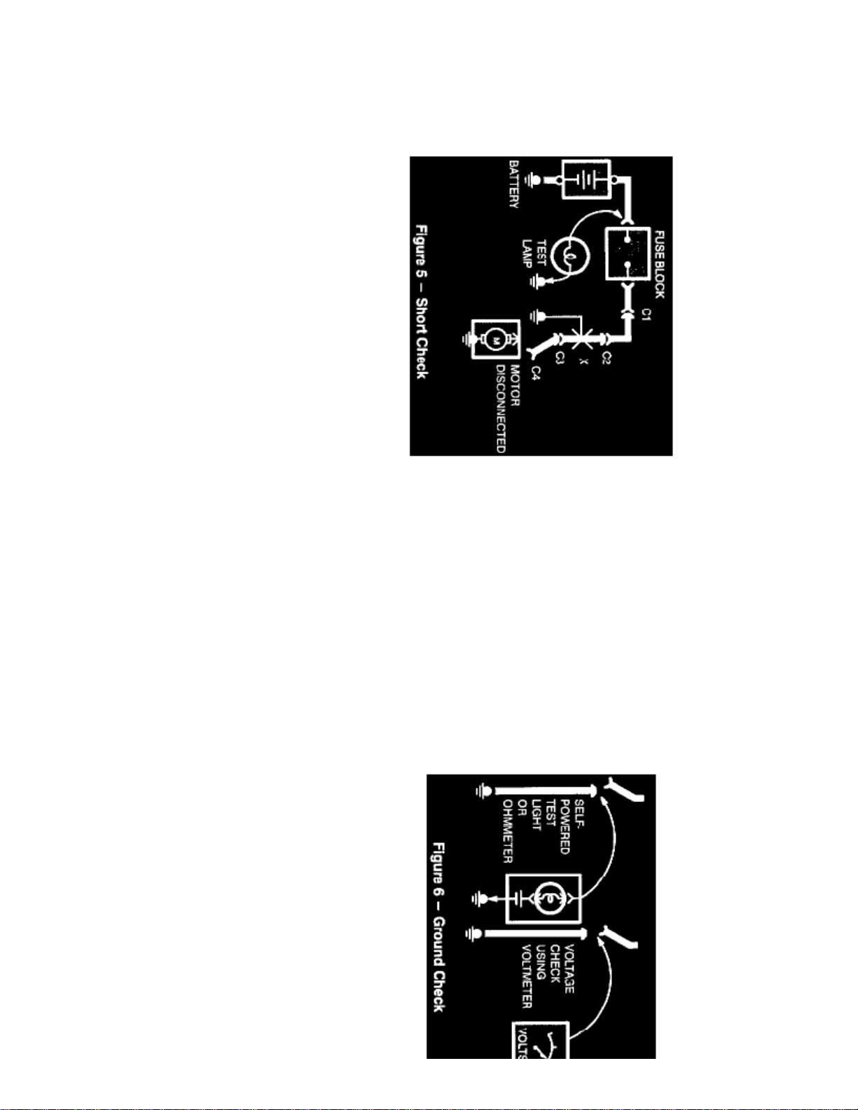
A fuse that repeatedly blows is usually caused by a short to ground. It's important to be able to locate such a short quickly.1. Turn off everything powered through the fuse.2. Disconnect other loads powered through the fuse:
- Motors: disconnect motor connector (Connector C4).
- Lights: remove bulbs.
3. Turn Ignition Switch to RUN (if necessary) to power fuse.4. Connect one Test Lamp lead to hot end of blown fuse. Connect other lead to ground. Bulb should glow, showing power to fuse. This step is
just a check to be sure you have power to the circuit)
5. Disconnect the test lamp lead that is connected to ground, and reconnect it to the load side of the fuse at the connector of the disconnected
component. (Connect the test lamp lead to connector C4).-
If the Test Lamp is off, the short is in the disconnected component.
-
GROUND CHECK
Page 81

> Relays and Modules > Relays and Modules - Cooling System > Radiator Cooling Fan Motor Relay > Component Information > Diagrams > Diagram Information and
Instructions > Page 73
Escort L4-122 2.0L SOHC VIN P SFI (1999)
If the Test Lamp goes on, the short is in the wiring. You must find the short by disconnecting the circuit connectors, one at a time, until theTest Lamp goes out. For example, with a ground at X, the bulb goes out when C1 or C2 is disconnected, but not after disconnecting C3.This means the short is between C2 and C3.
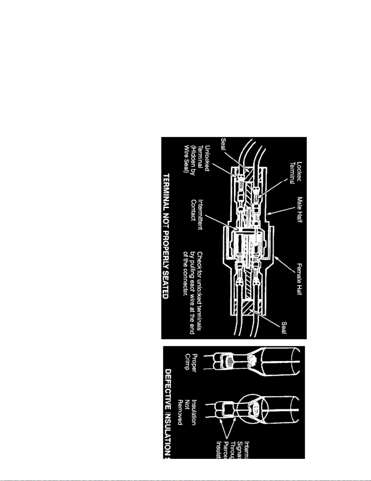
Turn on power to the circuit. Perform a Voltage Check between the suspected inoperative ground and the frame. Any indicated voltage means that theground is inoperative.
Turn off power to the circuit. Connect one lead of a Self-Powered Test Lamp or Ohmmeter to the wire in question and the other lead to a knownground. If the bulb glows, the circuit ground is OK.
DIAGRAMS
These diagrams make it easy to identify common points in circuits. This knowledge can help narrow the concern to a specific area. For example, ifseveral circuits fail at the same time, check for a common power or ground connection (see Power and Ground Distribution Diagrams). If part of a
Page 82
circuit fails, check the connections between the part that works and the part that doesn't work.
For example, if the lo beam headlamps work, but the high beams and the indicator lamp don't work, then power and ground paths must be good. Sincethe dimmer switch is the component that switches this power to the high beam lights and indicator, it is most likely the cause of failure.
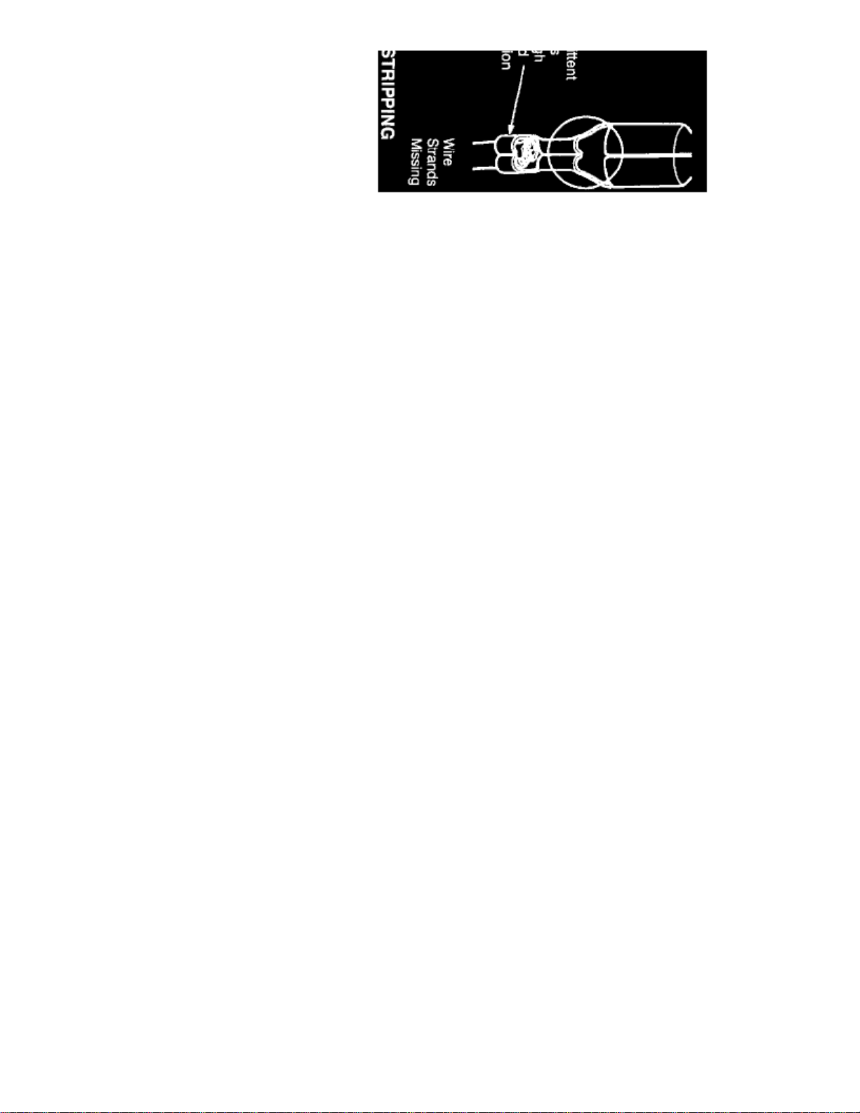
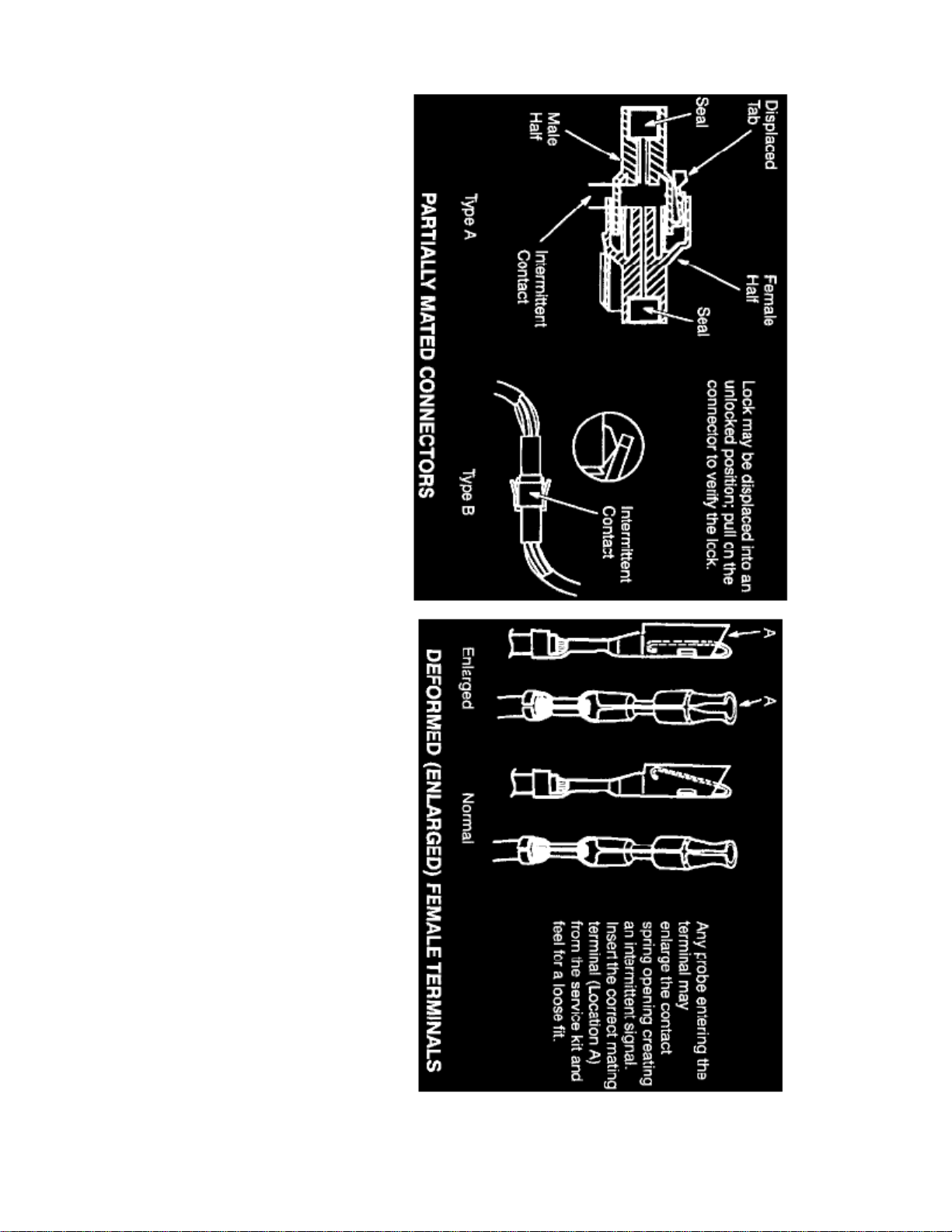
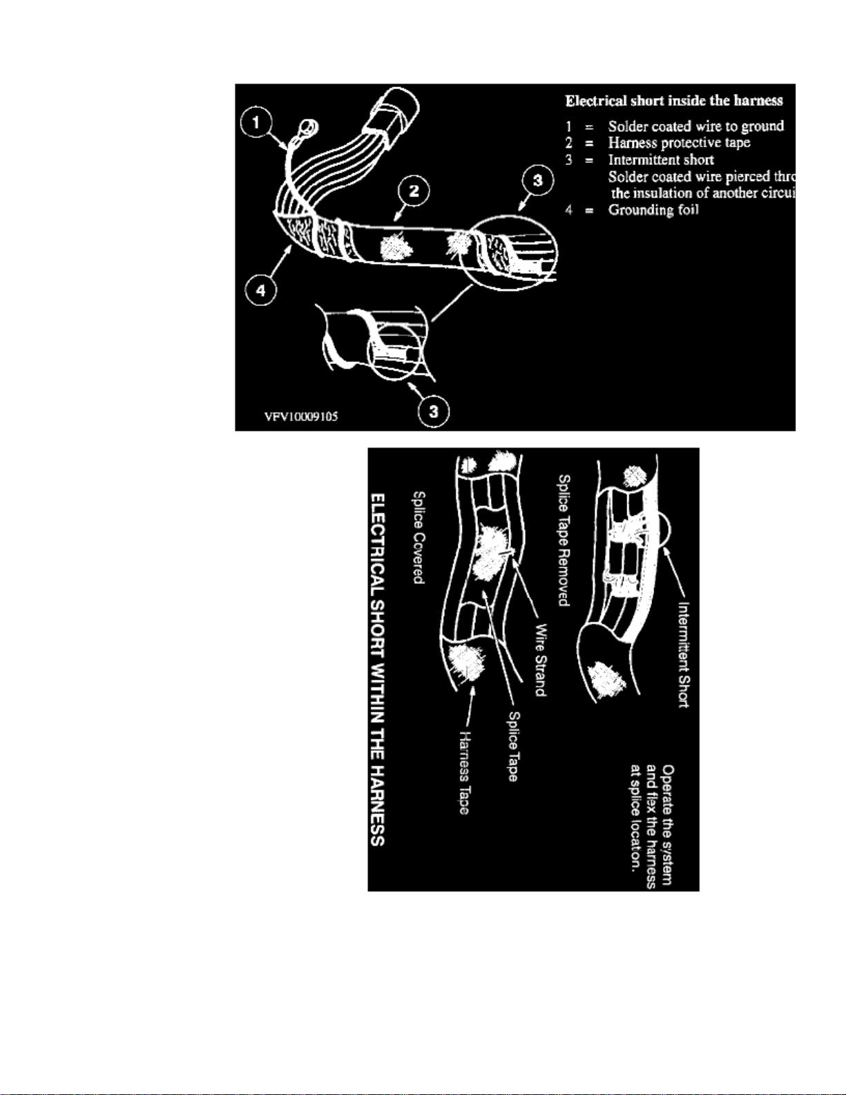
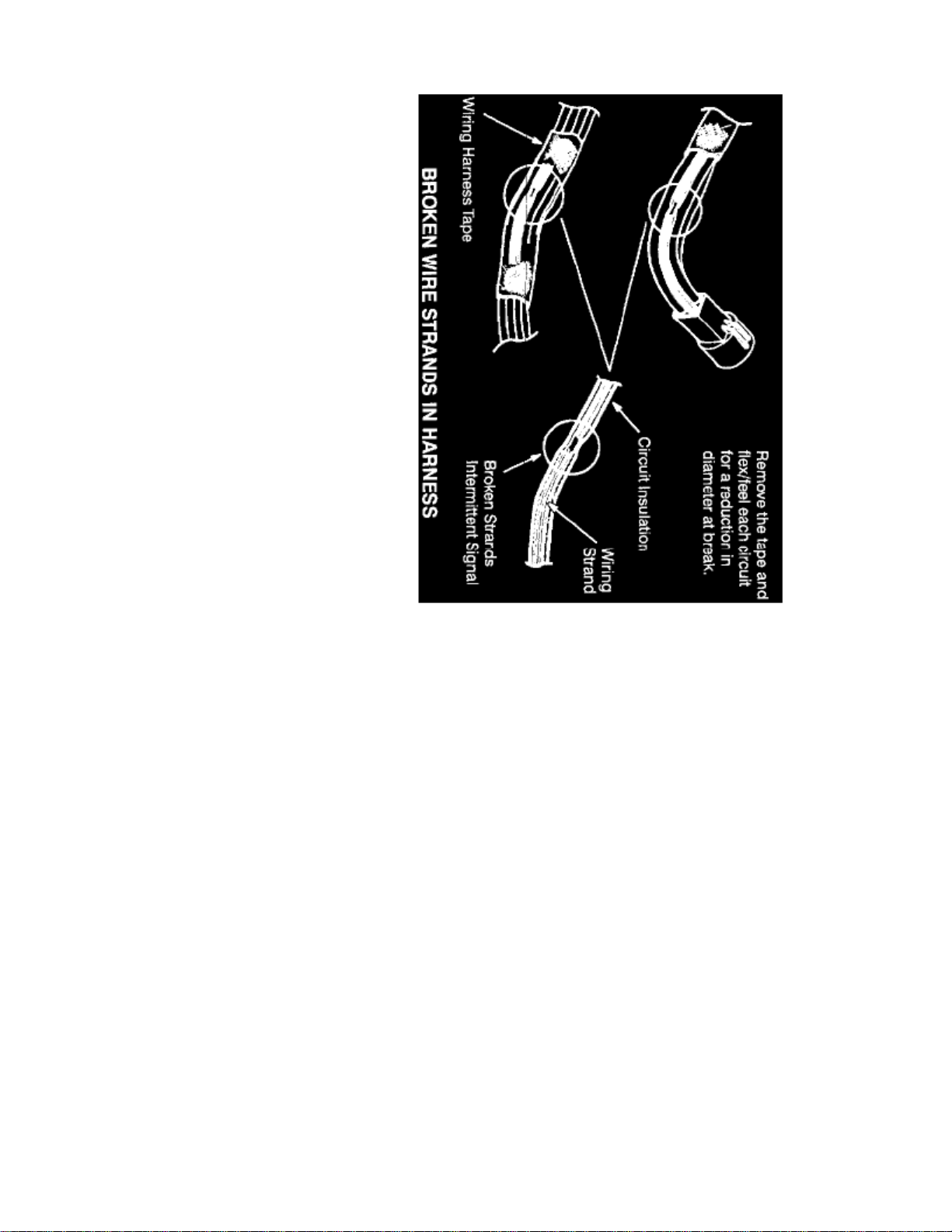
TROUBLESHOOTING WIRING HARNESS AND CONNECTOR HIDDEN CONCERNS
The following illustrations are known examples of wiring harness, splices and connectors that will create intermittent electrical concerns. The concernsare hidden and can only be discovered by a physical evaluation as shown in each illustration.
NOTE:
Several components, such as the PCM, utilize gold plated terminals in their connections to the wiring harness. If those terminals need to bereplaced, they must be replaced with a gold plated terminal.
Page 83
> Relays and Modules > Relays and Modules - Cooling System > Radiator Cooling Fan Motor Relay > Component Information > Diagrams > Diagram Information and
Instructions > Page 74
Escort L4-122 2.0L SOHC VIN P SFI (1999)
Page 84
Page 85

> Relays and Modules > Relays and Modules - Cooling System > Radiator Cooling Fan Motor Relay > Component Information > Diagrams > Diagram Information and
Instructions > Page 75
Escort L4-122 2.0L SOHC VIN P SFI (1999)
Page 86
Page 87

> Relays and Modules > Relays and Modules - Cooling System > Radiator Cooling Fan Motor Relay > Component Information > Diagrams > Diagram Information and
Instructions > Page 76
Escort L4-122 2.0L SOHC VIN P SFI (1999)
Page 88
Page 89

Page 90
> Relays and Modules > Relays and Modules - Cooling System > Radiator Cooling Fan Motor Relay > Component Information > Diagrams > Diagram Information and Instructions > Page 77
Page 91

Page 92
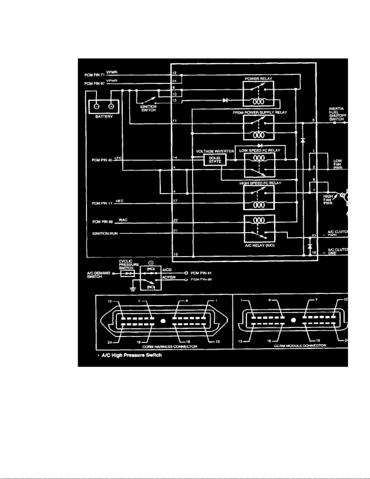
> Relays and Modules > Relays and Modules - Cooling System > Radiator Cooling Fan Motor Relay > Component Information > Diagrams > Diagram Information and Instructions > Page 78
Radiator Cooling Fan Motor Relay: Electrical Diagrams
Wiring Diagram
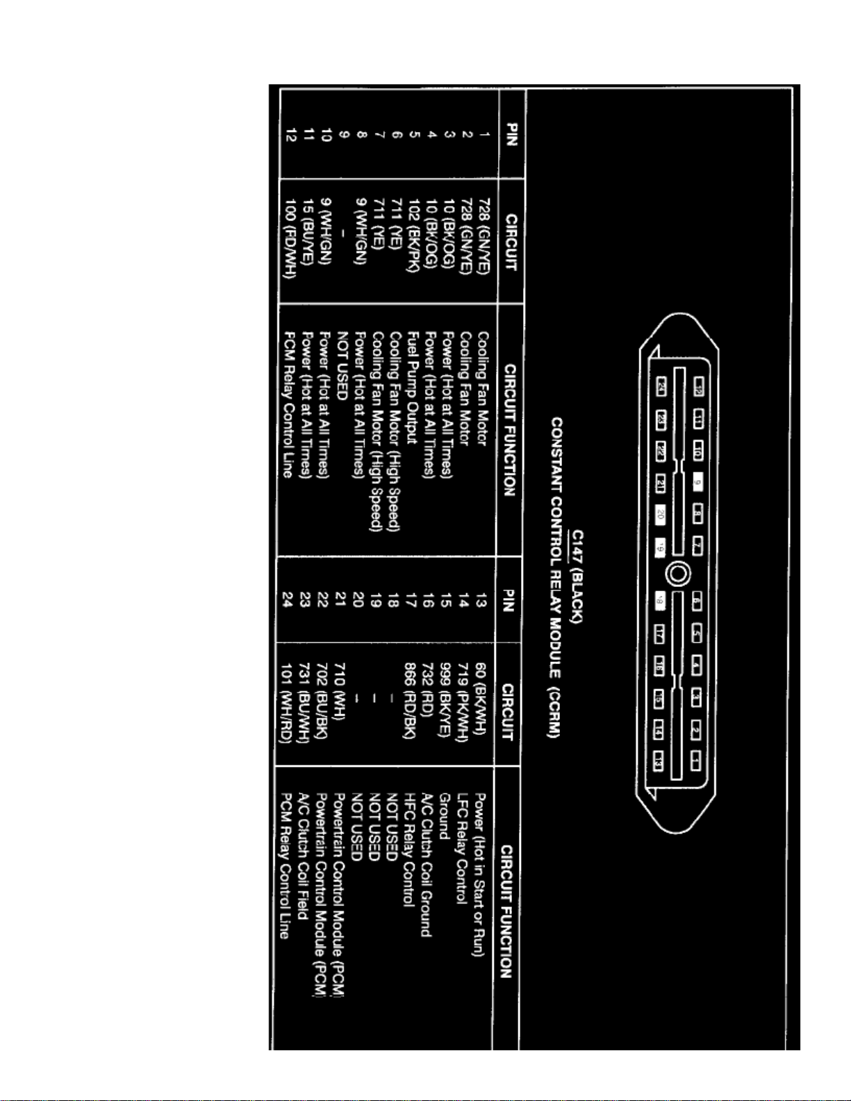
The wiring for the Constant Control Relay Module is included in each system that the module effects, the cooling fan system is included here for yourreference. The Internal Schematic is also available. See: Internal Schematic
Page 93

> Relays and Modules > Relays and Modules - Cooling System > Radiator Cooling Fan Motor Relay > Component Information > Diagrams > Diagram Information and
Instructions > Page 79
Escort L4-122 2.0L SOHC VIN P SFI (1999)
Page 94
Page 95

> Relays and Modules > Relays and Modules - Cooling System > Radiator Cooling Fan Motor Relay > Component Information > Diagrams > Diagram Information and
Instructions > Page 80
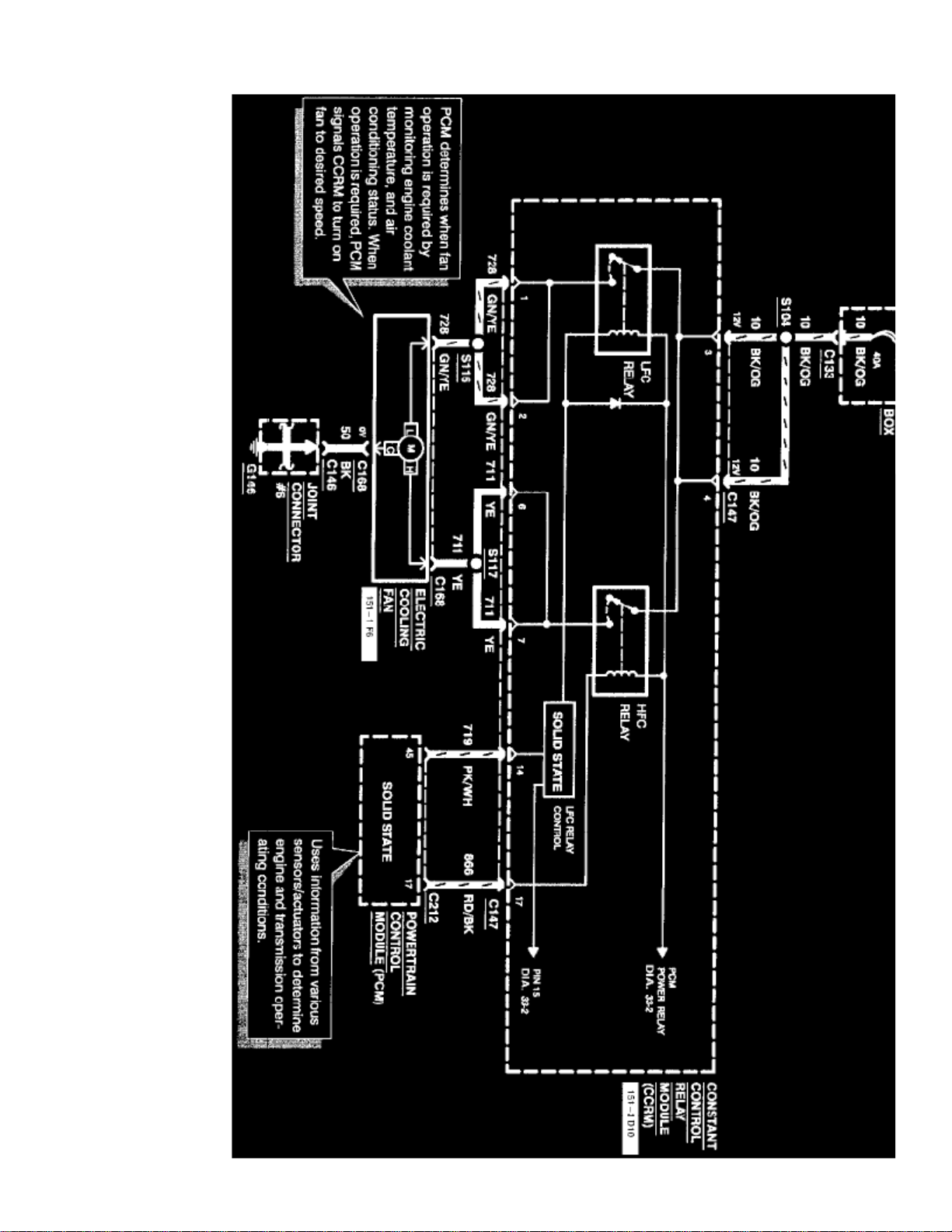
Escort L4-122 2.0L SOHC VIN P SFI (1999)
Diagram 33-1
Page 96
Page 97

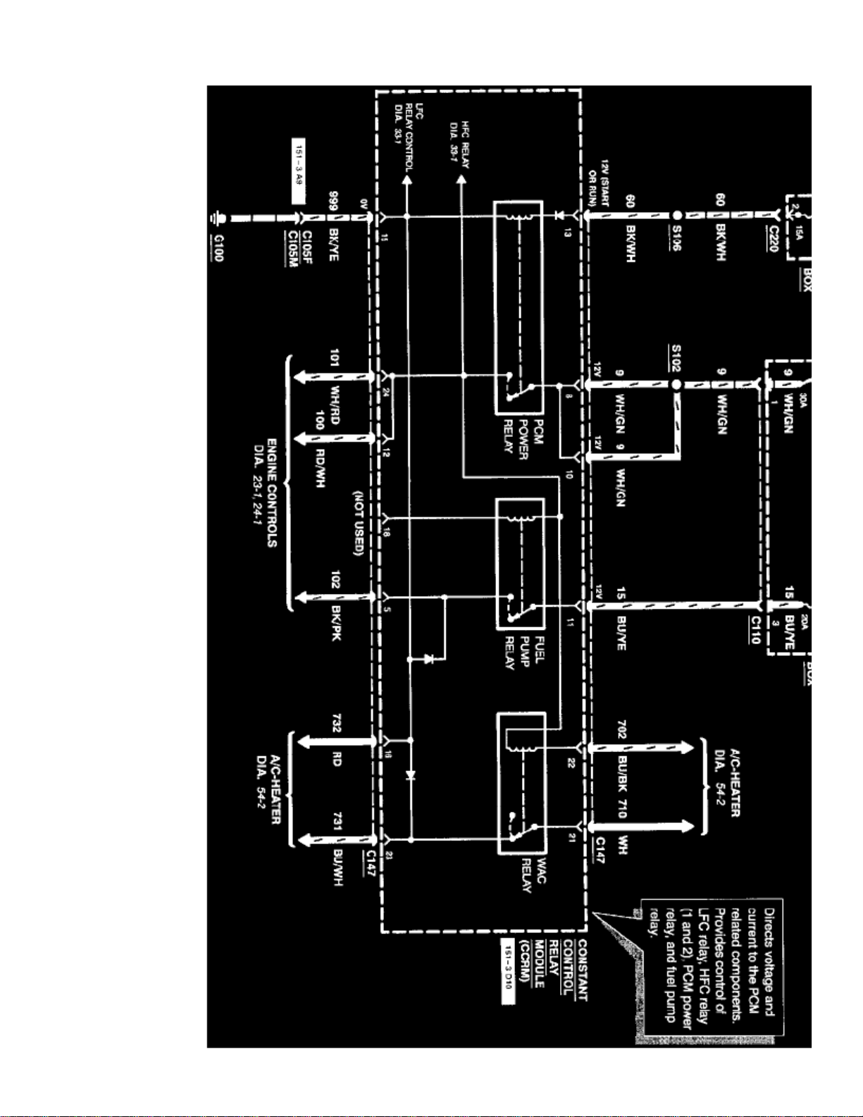
Diagram 33-2
Page 98
> Relays and Modules > Relays and Modules - Cooling System > Radiator Cooling Fan Motor Relay > Component Information > Diagrams > Page 81
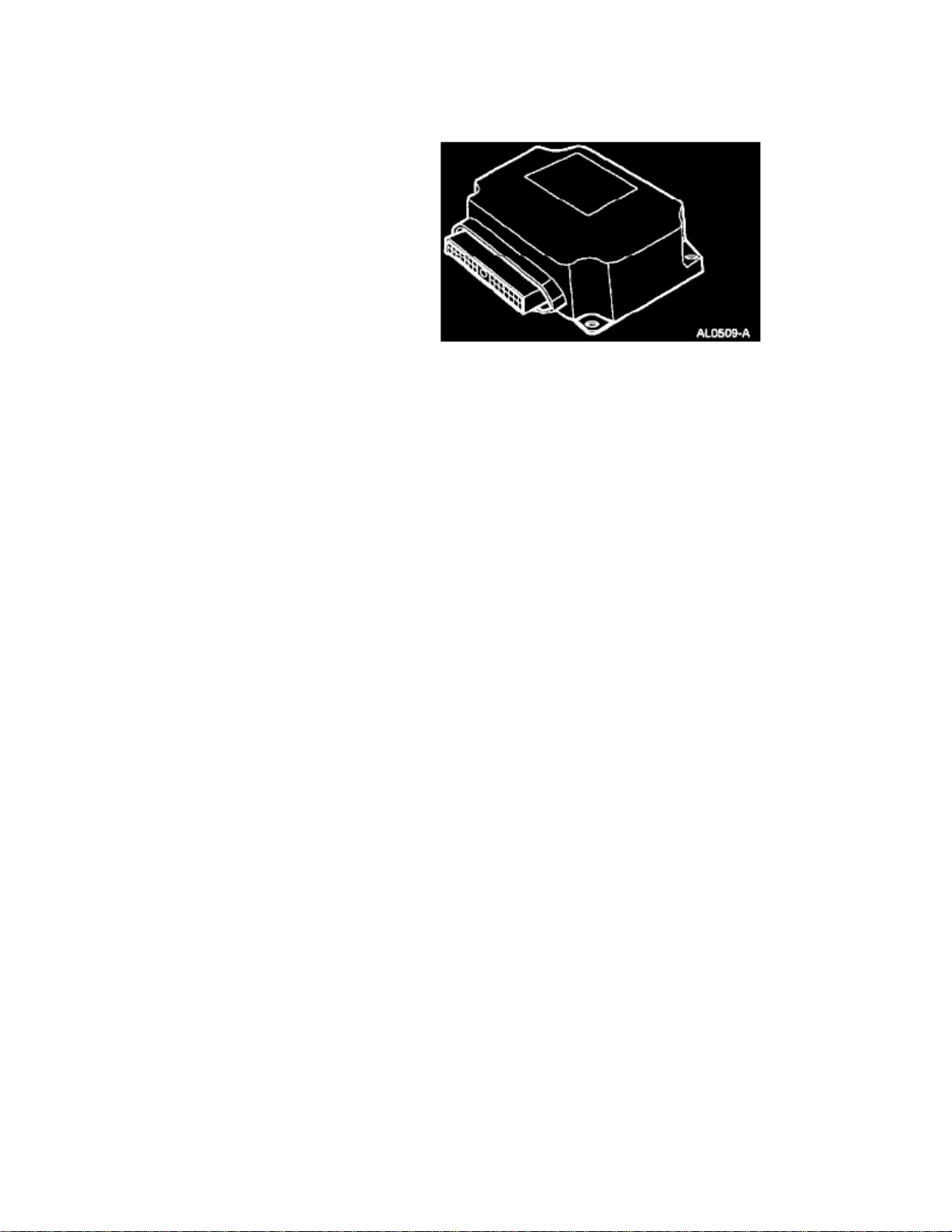
Radiator Cooling Fan Motor Relay: Description and Operation
The constant control relay module uses a combination of relays and solid state switches to control the following systems:
- Engine cooling fan
- A/C clutch
- Fuel pump
- Powertrain control module power
The powertrain control module can interrupt A/C compressor operation through the constant control relay module under the following conditions:
- During engine start-up
-
Wide Open Throttle (WOT)
- Low engine idle conditions
- Excessively high engine temperatures
Page 99

Page 100

> Relays and Modules > Relays and Modules - Cooling System > Radiator Cooling Fan Motor Relay > Component Information > Diagrams > Page 82
Radiator Cooling Fan Motor Relay: Service and Repair
No specific Removal sequence/procedure is given by the OEM, however we do have:
The Description. See: Relays and Modules - Powertrain Management/Relays and Modules - Computers and Control Systems/Integrated ControlRelay Module/Description and OperationThe Location. See: Relays and Modules - Powertrain Management/Relays and Modules - Computers and Control Systems/Integrated Control RelayModule/LocationsThe Torque Specs. See: Relays and Modules - Powertrain Management/Relays and Modules - Computers and Control Systems/Integrated ControlRelay Module/Specifications
 Loading...