

Page 1
Page 2
FOREWORD
This car maintenance manual provides the Service Technician
with complete information for the maintenance operations on all
1967 Ford, Lincoln and Mercury cars, and the Bronco, Econoline, Falcon Club Wagon and Recreational Vehicles.
The maintenance information is grouped in three parts.. maintenance schedule, maintenance operations, and lubrication charts
and specifications. The maintenance operations include in-vehicle
adjustments.
The descriptions and specifications in this manual were in effect
at the time this manual was approved for printing. The Ford
Motor Company reserves theligh.t to discontinue models at any
time, or change specifications or design, without notice and with-
out incurring obligation.
SERVICE PUBLICATIONS
Page 3
Page 4
Page 5
Page 6
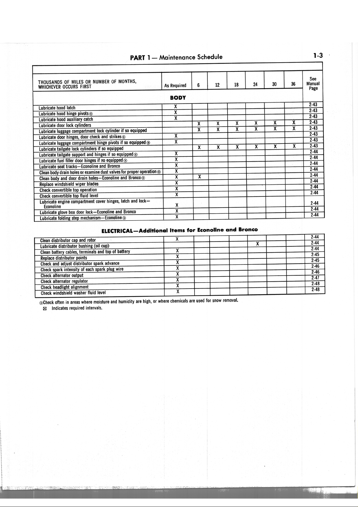
2-1
Secdoa
1 Engine 2 Transmission...
3 Chassis
Sedioa
4 Body .. 5 Electrical . . . . .
~ ..
.,,""",'" .. . . . . . .2-43
:.+;., 2-44
P-ce
2 -1
..2-20
.2-23
hicles cannot be covered in complete
detail here. If a vehicle is found to have
a special component installed that is
not fully covered herein, refer to the
Shop Manual for that vehicle for
complete details.
The maintenance operations described herein are to be considered as
minimum operations on vehicles which
are in operating condition and require
only periodic checkup and service. If,
upon inspection, a component requires
more than adjustment, cleaning or
simple replacement, refer to the applicable Group No. in the appropriate
Shop Manual for complete information.
All variations of all Ford-built ve-
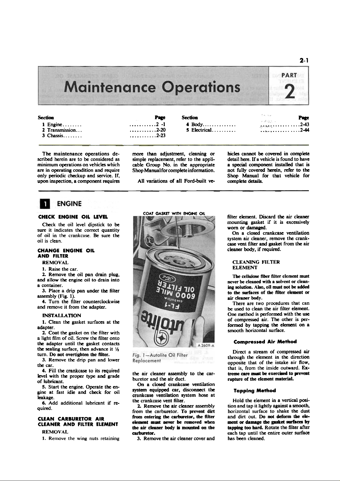
COAT GASKET WITH ENG-..E OIL
filter element. Discard the air cleaner
mounting gasket if it is excessively
worn or damaged-
On a closed crankcase ventilation
system air cleaner, remove the crankcase vent filter aOO gasket from the air
cleaner body, if required.
CLEANING FILTER
ELEMENT
The celluk)Se fiber filter element mlWt
never be cleaned with a solvent or cleaning solution. Also, oil mlWt Dot be added
to the surfaces of the filter element or
air cleaner body.
There are two procedures that can
be used to clean the air filter element.
One method is performed with the use
of compressed air. The other is performed by tapping the element on a
smooth horizontal surface.
Compressed Air Method
Direct a stream of compressed air
through the element in the direction
opposite that of the intake air flow,
that is, from the inside outward. Extreme care m- be exerc8ed to preYeat
rupture of the element material.
Tapping Method
Hold the element in a vertical position and tap it lightly against a smooth,
horizontal surface to shake the dust
and dirt out. Do not deform the element or damage tile gasket surfacs by
tapping too bard. Rotate the filter after
each tap until the entire outer surface
has been cleaned.
the air cleaner assembly to the carburetor and the air duct.
On a closed crank~ ventilation
system equipped car, disconnect the
crankcase ventilation system hose at
the crankcase vent filter.
2.. Remove the air cleaner assembly
from the carburetor. To prevent dirt
from enteriag the carburetor, the filter
element m1Bt never be removed when
the air cleaner body is m(Mlnted on the
carburetor.
3. Remove the air cleaner cover and
CHECK ENGINE OIL LEVa
Check the oil level dipstick to be
sure it indicates the correct quantity
of oil in the crankcase. Be sure the
oil is clean.
CHANGE ENGINE OIL
AND FILTER
REMOVAL
1. Raise the car.
2. Remove the oil pan drain plug,
and allow the engine oil to drain into
a container.
3. Place a drip pan under the filter
assembly (Fig. 1).
4. Turn the filter counterclockwise
and remove it from the adapter.
INSf ALLA nON
1. Clean the gasket surfaces at the
adapter.
2. Coat the gasket on the filter with
a light film of oil. Screw the filter onto
t~ adapter until the gasket contacts
the sealing surface, then advance it II,.
turn. Do not overtighten the filter.
3. Remove the drip pan and lower
the car.
4. Fill the crankCase to its required
level with the proper type and grade
of lubricant.
5. Start the engine. Operate the engine at fast idle and check for oil
leakage.
6. Add additional lubricant if required.
CLEAN CARBURETOR AIR
CLEANER AND FILTER ELEMENT
REMOVAL
1. Remove the wing nuts retaining
Page 7
2.2
PART 2
Maintenance Operations
CLEAN CRANKCASE OIL
FILLER aREA THER CAP
Remove the cap and wash it in a
low-volatility, petroleum-base solvent.
Probe the breather hole(s) to assure
removal of any accumulated deposits.
Shake the cap dry and install it. Do not
dry with compressed air as air pressure
may damage the filter element.
INSPEcriNG FILTER
ELEMENT
Hold the filter in front of a back-up
light and carefully inspect it for any
splits or cracks. If the filter is split or
cracked, replace it.
CLEANING BODY AND COVER
Clean the air cleaner body and cover
with a solvent or compressed air. Wipe
the air cleaner dry if a solvent is used.
Inspect the air cleaner body and cover
for distortion or damage at the gasket
mating surfaces. Replace the cover or
body if they are damaged beyond
repair.
the carburetor so that the word Front
faces the front of the car.
3. Place the air cleaner filter element
in the air cleaner body.
Make sure the filter is prolK!rly
seated. If the word TOP is ilMlicated on
the filter element, make sure the word
TOP faces up.
4. Install the cover and connect the
air in~t duct and valve assembly, if so
equipped, to the air cleaner with the
wing-type retaining screws. Tighten
the screws.
S. On a closed crankcase ventilation
system air cleaner, install the crankcase
vent filter and gasket in tlM: air cleaner
body, if it was previously removed.
Connect the crankcase vent hose to the
crankcase vent filter and tighten the
hose retaining clamp.
CLEAN AND REFILL OIL BATH
AIR CLEANER-ECONOLINE
AND BRONCO
INSfAUADON
1. Install a new air cleaner mount-
ing gasket on t~ carburetor. if nec-
essary .
2. Install the air cleaner body on
t~ carburetor so that t~ word Front
faces t~ front of t~ car.
3. Place the air cleaner filter element
in the air cleaner body. Make sure the
element is ..-opeIty leafed. Install the
cover and connect t~ air duct to the
air cleaner. Tighten the retaining wing
DUts.
On a closed crankcase ventilation
system air cleaner. install t~ crankcase vent filter and gasket in the air
cleaner body. if it was previously removed. Connect the crankcase vent
hose to t~ crankcase vent filter and
tighten t~ hose retaining clamp.
REMOVAL
1. Remove the carburetor to air
cleaner retaining wing nut.
On a cl~ crankcase ventilation
equipped engine, loosen the hose clamp
at the air cleaner body and disconnect
the hose.
On a 240 Six engine, remove the
bolts securing the air cleaner body to
the support brackets.
2. Remove the air cleaner. Use care
to prevent on spillage.
CLEANING AND INSPECflON
1. Drain the air cleaner reservoir.
Wash the air cleaner components and
duct (if so equipped) in cleaning solvent, and dry them with compressed
air.
CHECK AND ADJUST VALVE
LASH-MECHANICAL TAPPETS
It is very important that the valve
lash be held to the correct specifications because:
If the lash is set too close, the valve
will open too early and close too late,
resulting in rough engine idle. Burning
and warping of the valves will occur
also because the valves cannot make
firm contact with the seats long enough
to cool properly. If the lash is excessive,
it will cause the valve to open too late
and close too early causing valve
bounce. In addition, damage to the
crankshaft lobe is likely because the
tappet foot will not follow the pattern
of the camshaft lobe, causing a shock
contact between these two parts.
1. Be sure the engine is at normal
operating temperature before attempting to set the valve lash.
If the engine is cold, start and operate it for a minimum of 30 minutes at
1200 rpm to stabilize engine temperatures.
2. Remove the air cleaner and other
obstructing hardware.
3. Remove the valve rocker arm
cover and gaskets.
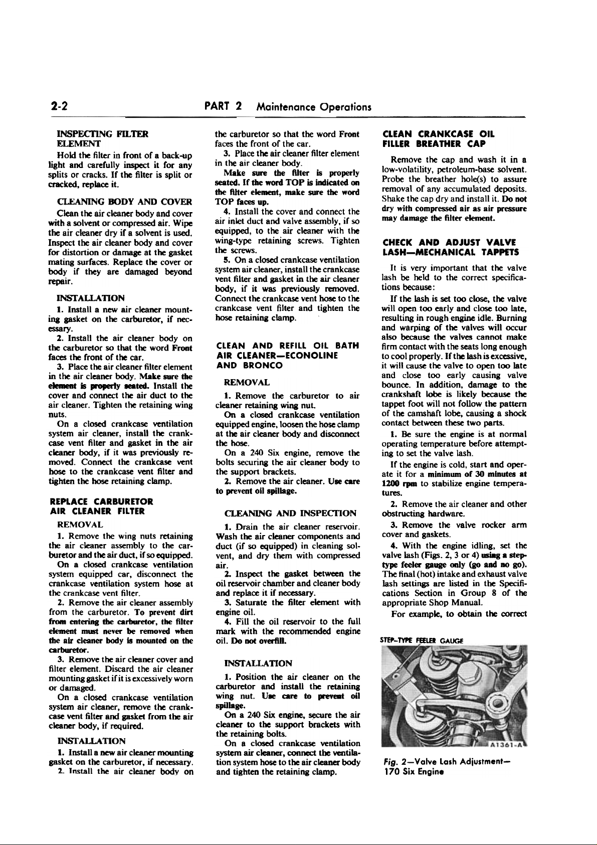
4. With the engine idling, set the
valve lash (Figs. 2, 3 or 4) .-i8g . step.
type feeler: gauge only (go and no go).
The final (hot) intake and exhaust valve
lash settings are listed in the Specifications Section in Group 8 of the
appropriate Shop Manual.
For example, to obtain the correct
2. Inspect the gasket between the
oil reservoir chamber and cleaner body
and replace it if necessary.
3. Saturate the filter element wittl
engine oil.
4. Fill the oil reservoir to the full
mark with the recommended engine
oil. Do not overfill.
STEP-TYPE fEELER GAUGE
REPLACE CARBURnOR
AIR CLEANER FILTER
REMOVAL
1. Remove the wing nuts retaining
the air cleaner assembly to the carburetor and the air duct, if so equipped.
On a closed crankcase ventilation
system equipped car, disconnect the
crankcase ventilation system hose at
the crankcase vent filter.
2. Remove the air cleaner assembly
from the carburetor. To prevent dirt
fnMII enteriDg the cariMlretor, the filter
element mlBt never be removed when
the air cleaner body is mounted on the
carburetor.
3. Remove the air cleaner cover and
filter element. Discard the air cleaner
mounting gasket if it is excessively worn
ordarnaged.
On a closed crankcase ventilation
system air cleaner, remove the crankcase vent filter and gasket from the air
cleaner body, if required.
INSI' ALLA nON
1. Install a new air cleaner mounting
gasket on the carburetor, if necessary.
2.. Install the air cleaner body on
INST ALLA nON
1. Position the air cleaner on the
carburetor and install the retaining
wing nut. UR care to ..-eveat oil
spillage.
On a 240 Six engine, ~re the air
cleaner to the support brackets with
the retaining bolts.
On a closed crankcase ventilation
system air cleaner, connect the ventilation system hose to the air cleaner body
and tighten the retaining clamp.
Fig. 2-Valve lash Adjustment-
170 Six Engine
Page 8
PART 2 - Maintenance Operations
2-3
Use the following procedure to run
in a new drive belt:
When installing new belt(s), first
adjust to new belt SpeclficatiOlW. (Refer
to Part 11-5 of the appropriate Shop
Manual.)
Run the engine for 10 minutes, then
check the tension of tbe belts to make
certain that they are within the reset
spedftca~. Adjust the belts, if required, to used belt spedfications.
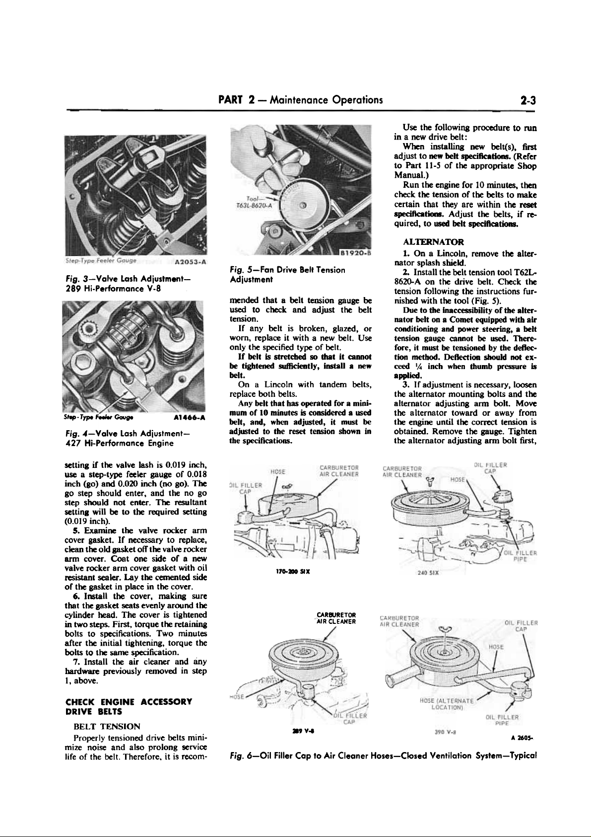
Fig. 5-Fan Drive Belt Tension
Adjustment
Fig. 3-Valve lash Adjustment289 Hi-Performance V-8
ALTERNATOR
1. On a Lincoln, remove the alter-
nator splash shield.
2. Install the belt tension tool T62L8620-A on the drive belt. Check the
tension following the instructions furnished with the tool (Fig. 5).
Due to the inaccessibility of the alternator belt on a Comet equipped with air
conditioning and power steering, a belt
tension gauge cannot be used. Therefore, it must be tensioned by the dellection method. DeOedion should not exceed 14 inch when thumb pressure is
applied.
3. If adjustment is necessary, loosen
the alternator mounting bolts and the
alternator adjusting arm bolt. Move
the alternator toward or away from
the engine until the correct tension is
obtained. Remove the gauge. Tighten
the alternator adjusting arm bolt first,
mended that a belt tension gauge be
used to check and adjust the belt
tension.
If any belt is broken, glazed, or
worn, replace it with a new belt. Use
only the specified type of belt.
If belt is stretched so that it cannot
be tightened sufficiently, install a new
belt.
On a Lincoln with tandem belts,
replace both belts.
Any belt that has operated for a minimum of 10 minutes is considered a ~ed
belt, and, when adjusted, it must be
adjusted to the reset tension sbown in
the specifications.
S/ep- Type Feeler ~ge A1466-A
Fig. 4-Valve lash Adjustment427 Hi-Performance Engine
setting if the valve lash is 0.019 inch,
use a step-type feeler gauge of 0.018
inch (go) and 0.020 inch (no go). The
go step should enter, and the no go
step should not enter. The resultant
setting will be to the rtXIuired setting
(0.019 inch).
5. Examine the valve rocker arm
cover gasket. If necessary to replace,
clean the old gasket off the valve rocker
arm cover. Coat one side of a new
valve rocker arm cover gasket with oil
resistant sealer. Lay the cemented side
of the gasket in place in the cover.
6. Imtall the cover, making sure
that the gasket seats evenly around the
cylinder head. The cover is tightened
in two Steps. First, torque the retaining
bolts to specifications. Two minutes
after the initial tightening, torque the
bolts to the same specification.
7. Install the air cleaner and any
hardware previously removed in step
1, above.
170.- SIX
CARaJRETOR
'AIR CLEANER
»9 V..
CHECK ENGINE ACCESSORY
DRIVE BELTS
BELT TENSION
Properly tensioned drive belts minimize noise and also prolong ~rvice
life of the belt. Therefore, it is recom-
A 2605-
Fig. 6-0il Filler Cap to Air Cleaner Hoses-Closed Ventilation System-Typical
Page 9
\ \
PART 2 - Maintenance Operations
INTAKE MANIFOl.D
C~HECTI<»I
...
1700310 SIX
VIEW.
,HOSE
/
i
rCLAMP
' VEN'
.ATOR VALVE
I
~E
and then the mounting bolts. Install
the tension gauge and check the belt
tension.
4. On a Lincoln, install the alter-
nator splash shield.
POWER STEERING
I. Loosen the mounting bolts incorporated on the front face of the
pump cover plate (hub side) and the
one nut at the rear.
1. Fix a 9/I6-inch open end wrench
on the projecting l/2-inch boss and pry
upward to correct tension. Do DOt pry
against the resenoir to obtain proper
belt load as it can be deformed and
cause a leak.
3. Recheck the belt tension. When
the tension has been correctly adjusted,
tighten the bolts to specifications.
AIR CONDmONING
Adjust the belt by repositioning the
idler pulley if so equipped. Otherwise,
follow this procedure:
I. Loosen the bolts securing the
compressor to the compressor mounting bracket. On a Lincoln. first remove
the bolts securing the compressor to
the support bracket that is attached to
the cylinder head.
1. Install the tension gauge on the
compressor clutch drive belt. Move
the compressor toward or away from
the engine until the specified belt tension is obtained. Remove the gauge.
Tighten the compressor to support
bracket bolts. Install the tension gauge
and check the belt tension.
THERMACTOR AIR PUMP
I. Loosen the air supply pump ad-
justIng arm nut and bolt.
1. Loosen the air supply pump
mounting bracket nut and bolt.
3. Move the air pump toward or
away from the engine until the correct
tension is obtained. UE a suitable bar
and IWY agalDSt the JKIInp rear cover to
hold belt tension while tightening the
mounting bolts. Do not IWY agaiDSt the
pump boI8ing. Remove the gauge.
Tighten the air pump adjusting arm
and mounting bolts. Install the tension
gauge and check the belt tension.
Roc:KER ~
COVER
~~~~~~~(/'
~ OIL FILLER
" CAP
. ~~https://manualmachine.com/
I
"
~,:¥:
--~~
.:\i.
"-
r-t'J}
[ ~ ""~
~
~~ . ..
- --
~ , '. ~.-i1
~"""~'
~:" ~.- ' ~~
j~"\.. ' L'
Ii'-"-~'-"""
~ "rr~ .' --- ='- '.
r;(o'
J {"'- v
')~~;~~ INTAKE MANIFOL~ ,~~" ~" /"
~~', J
NIPPLE '~'" "-/ ( I tJJ--;.P
,:~=... I l
CLEAN POSITIVE CRANKCASE
VENTILATION SYSTEM
COMPONENTS-ALL VEHICLES
EXCEPT LINCOLN
Current production vehicles which
are equipped with positive crankcase
vehtilation systems have the components located at different points on
each type of engine. The following
procedure is a general procedure. Specific procedures will be found in Group
240 SIX
A~A
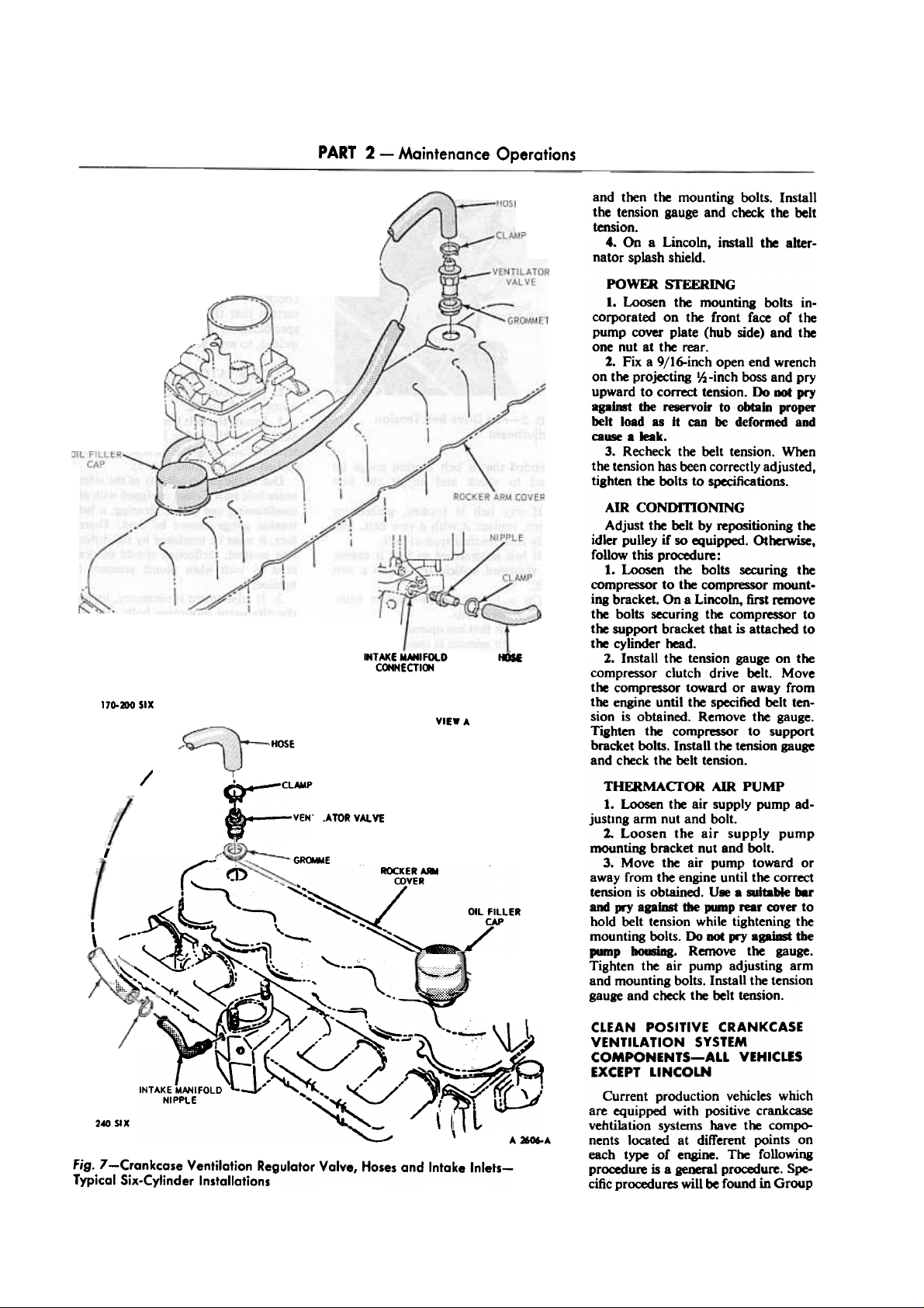
Fig. 7-Crankcase Ventilation Regulator Valve, Hoses and Intake InletsTypical Six-Cylinder Installations
Page 10
2-5PART 2
Maintenance Operations
8 of the Shop Manual for the vehicle
being serviced .
REMOVAL OF COMPONENfS
Closed Ventilation System
Remove the following components
from the crankcase ventilation system.
Figs. 6 through 9 show typical components which should be removed.
Refer to Group 8 of the appropriate
Shop Manual for specific removal
procedures.
1. Remove the oil filler cap and its
connecting hose to the air cleaner.
1.. Remove the air cleaner (and ducts,
if so equipped). Refer to Group 10 of
the appropriate Shop Manual for specific removal procedures.
3. Remove the hose (Figs. 7 or 8) oj'
hose assembly (Fig. 9) from the venti.
lator valve in the rocker arm cover.
Remove the other end of this hose (or
hose assembly) from the intake manifold connection, or carburetor spacer
connection, if so connected.
If a hose aSlembly was removed,
disassemble the hoses from the tee or
hot idle compensator, if so equipped.
4. Pull the ventilator valve from
grommet in the rocker arm cover.
Discard the ventilator valve 8S8eI8JIy.
Open Ventllotlon System
Remove the following components
from the crankcase ventilation system.
Figs. 6 through 9 show typical components which should be removed.
Refer to Group 8 of the appropriate
Shop Manual for specific removal
procedures.
1. Remove the hose (Fias. 7 or 8)
or hose assembly (Fig. 9) from the
ventilator valve in the rocker arm
cover. Remove the other end of this
hose (or hose assembly) from the intake manifold connection, or carburetor spacer connection if so connected.
If a hose assembly was removed,
disassemble the hoses from the tee or
hot idle compensator. if so equipped.
1.. Pull the ventilator valve from the
grommet in the rocker arm cover.
DiIC8rd die ventilator valve 88emb1y.
CLEANING
Closed Ventilation System
1. Wash the crankcase filler cap in
a low-volatility, petroleum-base solvent. Shake the cap dry. Do not dry
with ~pressed air. since air ~
may damage the filter element.
2. Remove the crankcase ventilation
air filter (screen type) from the carburetor air cleaner body and clean it,
using the ~ procedure as in step 1,
and re-install it into the air cleaner
body.
A »O7-A
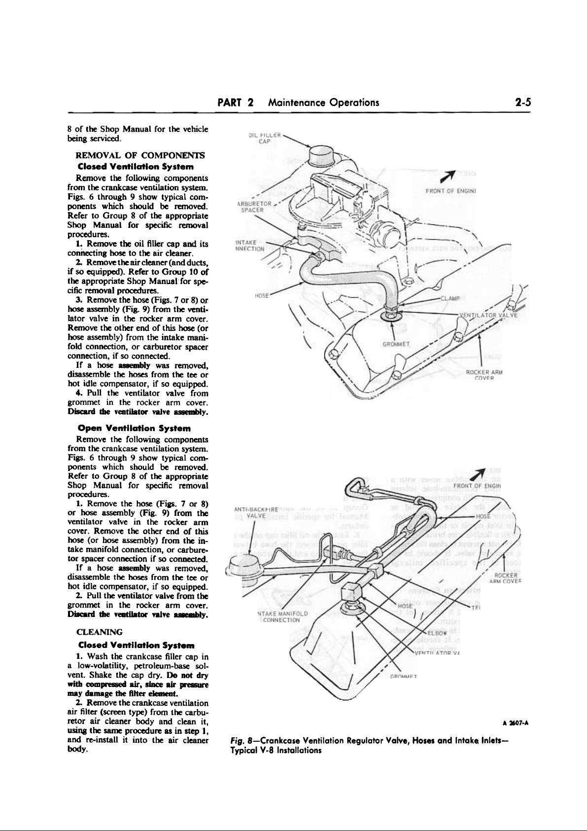
Fig. 8-Crankcase Ventilation Regulator Valve, Hoses and Intake Inlets-
Typical V-8 Installations
Page 11
PART 2 - Maintenance Operations
2-6
HO11DLE C~PENSATOR
CARBURETOR
SPACER
CONNECTING
NIPPLE
Open Ventilation System
Follow the same procedure outlined
in steps 1 thru 4 for the Closed Ventilation System, above.
HOSE
HOSE ~.
-VENTltAJ-9R
'~ - VALVE"
/,-,
:LAMPS
~
', /;;
v
A ROCKER ARM
COVER
HOT IDLE COMPEHSATOR HOSE ASSEMBLY
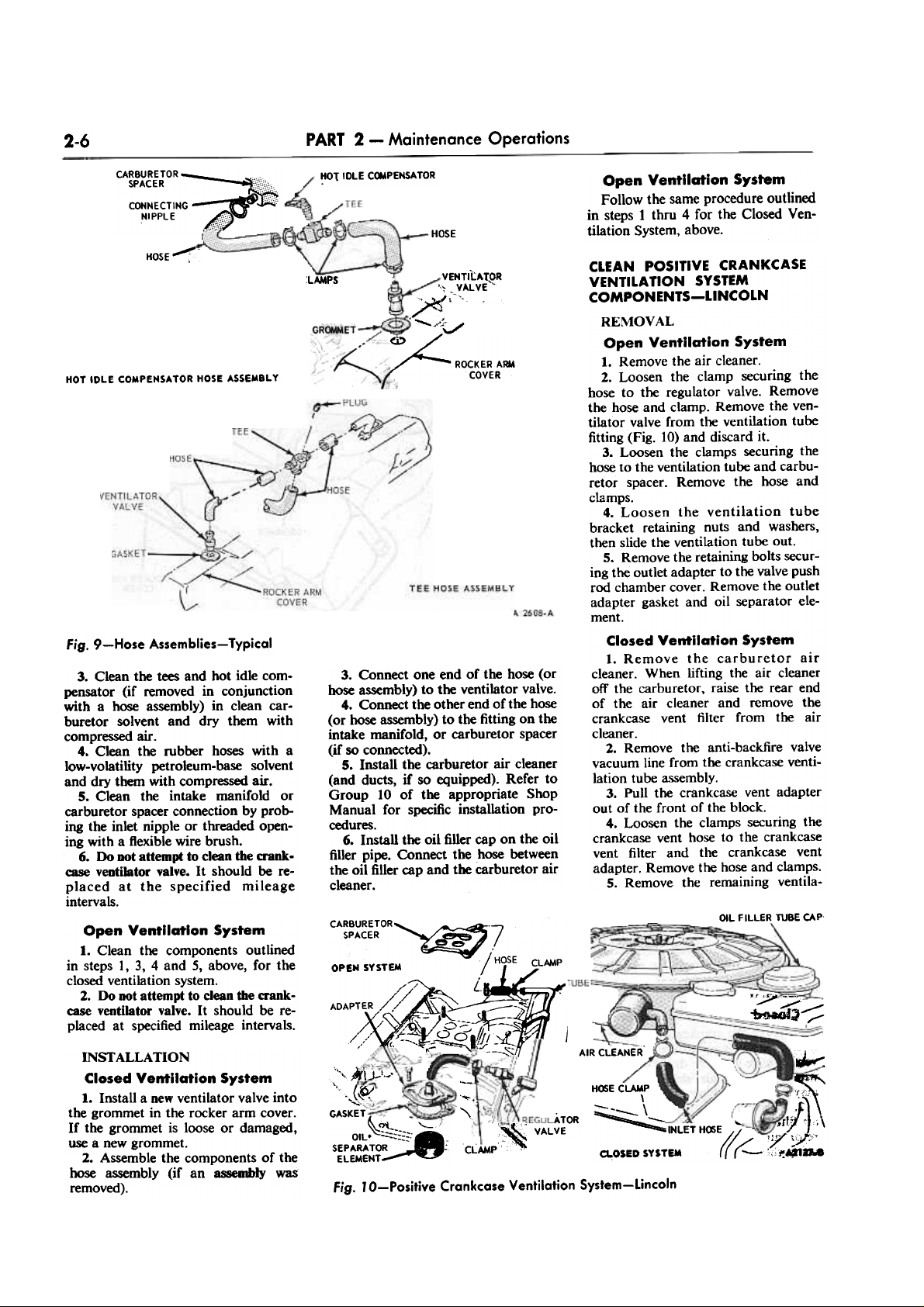
Fig. 9-Hose Assemblies-Typical
CLEAN POSITIVE CRANKCASE
VENTILATION SYSTEM
COMPONENTS-LINCOLN
REMOVAL
Open Ventilation System
1. Remove the air cleaner.
2. Loosen the clamp securing the
hose to the regulator valve. Remove
the hose and clamp. Remove the ventilator valve from the ventilation tube
fitting (Fig. 10) and discard it.
3. Loosen the clamps securing the
hose to the ventilation tube and carburetor spacer. Remove the hose and
clamps.
4. Loosen the ventilation tube
bracket retaining nuts and washers,
then slide the ventilation tube out.
5. Remove the retaining bolts securing the outlet adapter to the valve push
rod chamber cover. Remove the outlet
adapter gasket and oil separator element.
Closed Ventilation System
1. Remove the carburetor air
cleaner. When lifting the air cleaner
off the carburetor, raise the rear end
of the air cleaner and remove the
crankcase vent filter from the air
cleaner.
2. Remove the anti-backfire valve
vacuum line from the crankcase ventilation tube assembly.
3. Pull the crankcase vent adapter
out of the front of the block.
4. Loosen the clamps securing the
crankcase vent hose to the crankcase
vent filter and the crankcase vent
adapter. Remove the hose and clamps.
5. Remove the remaining venti la-
3. Connect one end of the hose (or
hose assembly) to the ventilator valve.
4. Connect the other end of the hose
(or hose assembly) to the fitting on the
intake manifold, or carburetor spacer
(if so connected).
5. Install the carburetor air cleaner
(and ducts, if so equipped). Refer to
Group 10 of the appropriate Shop
Manual for specific installation pro-
cedures.
6. Install the oil filler cap on the oil
filler pipe. Connect the hose between
the oil filler cap and the carburetor air
cleaner.
3. Clean the tees and hot idle compensator (if removed in conjunction
with a hose assembly) in clean carburetor solvent and dry them with
compressed air.
4. Clean the rubber hoses with a
low-volatility petroleum-base solvent
and dry them with compressed air.
5. Clean the intake manifold or
carburetor spacer connection by probing the inlet nipple or threaded opening with a flexible wire brush.
6. Do DOt attempt to clean the crank-
case ventilator valve. It should be replaced at the specified mileage
intervals.
OIL FILLER TU8E CAP
CAR8URETOR,,/~ ~
SPACER ~~7' ,7
OPEN SYSTEM I'HOSE CLAMP
~/ L.
AOAPTER /,~ -It :
/ ,(i\-)O-;;:-~-
/,//' {,~~~I&~ '" !
Open Ventilation System
1. Clean the components outlined
in steps 1, 3, 4 and 5, above, for the
closed ventilation system.
2. Do not attempt to clean the crankcase ventilator valve. It should be re-
placed at specified mileage intervals.
":? ? '/
~~,
AIR CLEANER'
'~
,~
..~J};\
;7t~,;"
:;;~~
~,
""'.
""
ATOR
VALVE
H~EC~
\
'"'-.
\~ -.~~
- '"'
INLET H~E 1/
a,OSED SYSTEM (( r-::::-
'.. ...
" 161:\.)-1_,
\
c.
('tII
~,
'.:.
GASKET
-<-.i"- ,--.
OIL~:-'-:
~~f':::: -
SEPARATOR :;
ELEMENT
~ ~' ,~
CC',
.CLAMP
INSTALLAllON
Closed Ventilation System
1. Install a new ventilator valve into
the grommet in the rocker arm cover.
If the grommet is loose or damaged,
use a new grommet.
2. Assemble the components of the
hose assembly (if an assembly was
removed).
Fig. la-Positive Crankcase Ventilation System-Lincoln
Page 12
PART 2
Maintenance Operations
2-7
tion system parts by following steps 2
through 5 under Open Ventilation
System.
4. Install the hose and clamp on the
outlet adapter and ventilator valve.
Position and tighten the clamp.
5. Install the hose and clamps on
the carburetor and ventilation tube.
6. Install the air cleaner.
ADJUST CARBURETOR
ACCELERATOR PUMP LEVER,
IDLE SPEED, IDLE MIXTURE,
AND FAST (COLD) IDLE SPEED
The following procedures apply to
automatic choke type carburetors only.
Manual choke carburetor adjustment
procedures are given at the end of this
group of procedures.
Closed Ventilation System
1. Follow steps 1 through 5 under
Open Ventilation System.
2. Connect the anti-backfire valve
vacuum line to tre crankcase ventilation tube assembly (Fig. 9).
3. Install the crankcase vent hose
and clamps on the crankcase vent
filter and the crankcase vent adapter.
4. InstaU the air cleaner and connect
the crankcase vent filter to the air
cleaner.
REPLACE THERMACTOR AIR
CLEANER ELEMENT, IF SO
EQUIPPED
1. Remove the wing nut (Fig. 11)
and air horn assembly. Remove the
filter element from the air horn as-
sembly.
2. Wipe the air horn assembly and
air cleaner with a clean, dirt-free cloth
to remove any accumulated dirt or
foreign matter. Under extremely dirty
conditions it may be ~ to wash
both the air horn and body in lowvolatility mineral spirits. Be sure the
parts are dry before installing them.
3. The filter element ~ not cleanable.
Place a new filter element on the air
horn assembly. Position the assembled
air horn and filter element in the air
cleaner body. Be sure the tang ~ fitted
in the sI~ (Fig. 11). Install the wing nut.
4. Start the engine and check for
leaks. Refer to Part 8-1 of the appropriate Shop Manual for procedures for
testing for proper operation.
",c
CLEANING
Closed Ventilation System
1. Wash the crankcase filler cap in a
low-volatility, petroleum-base solvent.
Shake the cap dry. Do not dry with
compressed air. since air pressure may
damage the filter element.
2. Remove the crankcase ventilation
air filter from the carburetor air cleaner
body and clean it, using the same
procedure as in step I, and re-install
it on the air cleaner body.
3. Clean the oil separator element
and long ventilator tube in clean carburetor solvent a~ dry them with
compressed air.
4. Clean the rubber hoses with a
low-volatility, petroleum-base solvent
and dry them with compressed air.
5. Clean the carburetor spacer con-
nection by probing the inlet nipple
with a flexible wire brush.
6. Do DOt attempt to clean tile cruk-
case ventilator valve. It should be replaced at the specified mileage intervals.
INSTALLAllON
Open Ventilation System
1. Install the oil separator element
in the valve push rod chamber cover
(Fig. 10). Make certain the screen is
positioned snugly around the edges of
the opening.
2. Coat a new outlet adapter gasket
with oil-resistant sealer and position it
on the push rod chamber cover. Position the outlet adapter on the cover and
install the retaining bolts.
3. Slide the ventilation tube brackets
under the retaining washers and nuts.
Tighten the nuts. Install a new ventilator valve in the ventilation tube fitting.
F/t.T£R fl-E~N
AIR HMN ~SE~LY
~'.
'.
'.
i "
\~r
~
;/
~
AIRCLEAN£R BOOY
~
...
A"
~
PRELIMINARY PREPARATION
-ALL VEHICLES
The engine idle speed is adjusted to
settings for a hot engine and a cold
engine (fast idle speed during choke
operation). All final idle speed and
mixture adjustments must be made on
a hot, norma~ engine.
Refer to Figs. 12 through 20 for
views of the idle fuel mixture and idle
(hot engine) speed screws for the various carburetor applications.
I, Operate the engine until engine
temperatures are stabilized. On . car
with an air conditioner, operate the
engine for twenty minutes before setting
the engine idle speed. The engine idle
speed is adjusted with the air conditioner
operating.
2. Position the transmission lever in
neutral. Allow the throttle to drop
back to the normal idle speed position.
Attach a tachometer to the engine. Set
the parking brake.
On cars equipped with a vacuum
release parking brake, remove the
vacuum line from the vacuum power
unit of the automatic vacuum release
parking brake assembly, and plug the
vacuum line. Set the parking brake. It
is necegary to Inactivate the 'facuum
power unit to keep the parking brake
engaged when the engine is running during the adj4fitment procedures.
3. Turn on the head lamps. It is
necessary to place the alternator under
a load condition in this manner in order
to obtain the specified engine idle speed
during the ad~ment procedure.
4. On a car with a manual-shift transmission, the engine idle speed is checked
and adjusted with the gear shift lever in
neutral position. On a car with an automatic transmission, the engine idle
speed is checked and adjusted first with
the transmission selector lever in the
neutral position and readjusted with the
transmission selector lever in the drive
range position. Adjust and check the
engine idle speed. Be sure the dash pot
(if so equipped) is not interfering with
the throttle lever or the fast idle screw
is not contacting the fast idle eam.
On a carburetor equipped with a hot
idle compensator, be sure the compensator is seated to ailow for proper idle
adjustment.
'-2298-A
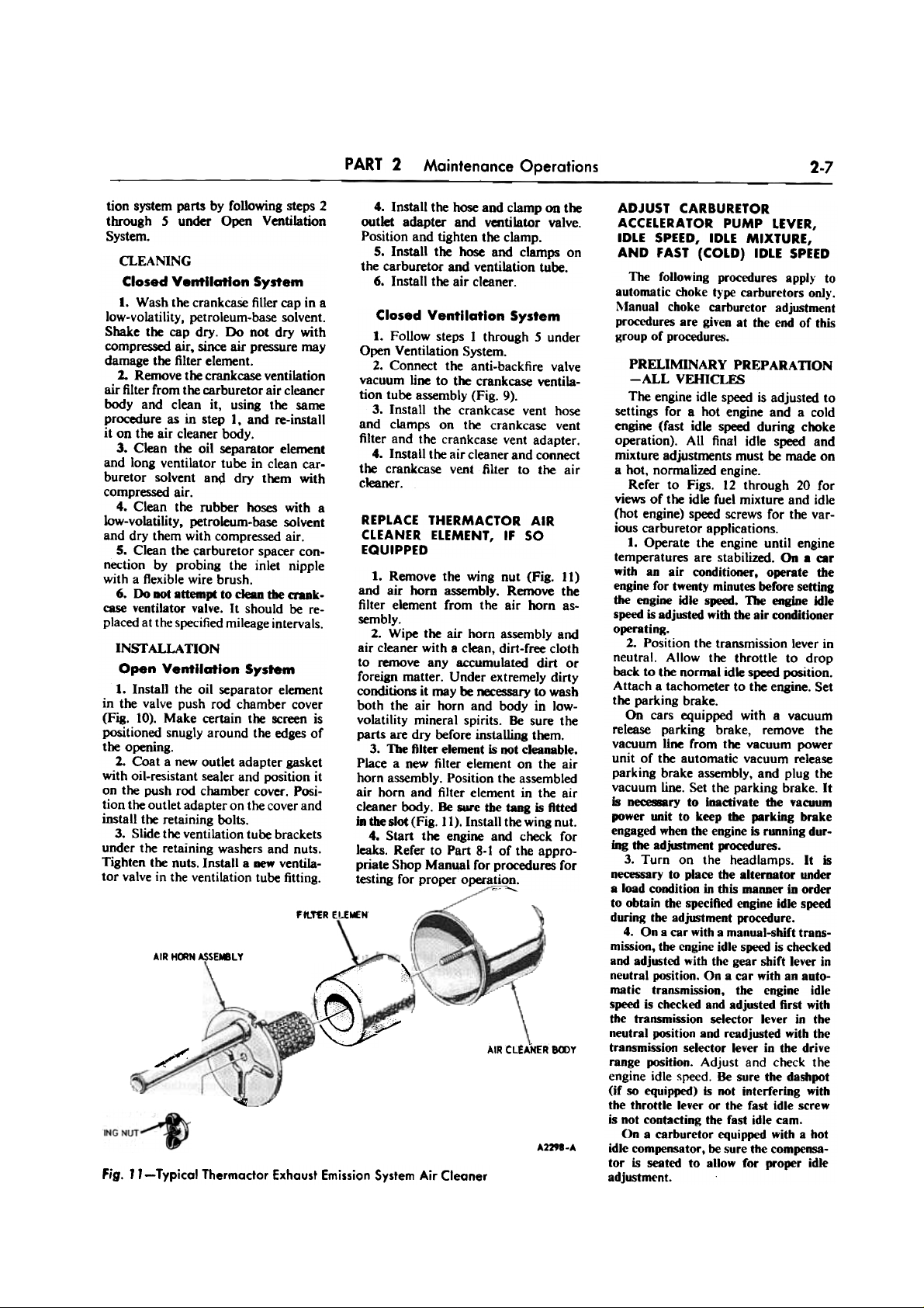
Fig. " -Typical Thermador Exhaust Emission System Air Cleaner
Page 13
2-8
PART 2 - Maintenance Operations
When checking or adjusting idle (hot
engine) speed on any Thecmactor
equipped engine with a thermal sensing
valve in the distributor vacuum line,
die valve m..t be bypassed. Disconnect
the distributor vacuum' hose at the
sensing valve. Plug or pinch~ff the
manifold vacuum hose; t~n cbeckor
adjust the idle speed in the normal
manner. Do not unplug and reconnect
the hose until after the fast idle (cold
engine) speed adjustments havt been
completed.
FORD t-V CARBURETOR
Refer to Preliminary PreparatioD-
All Vehicles, above.
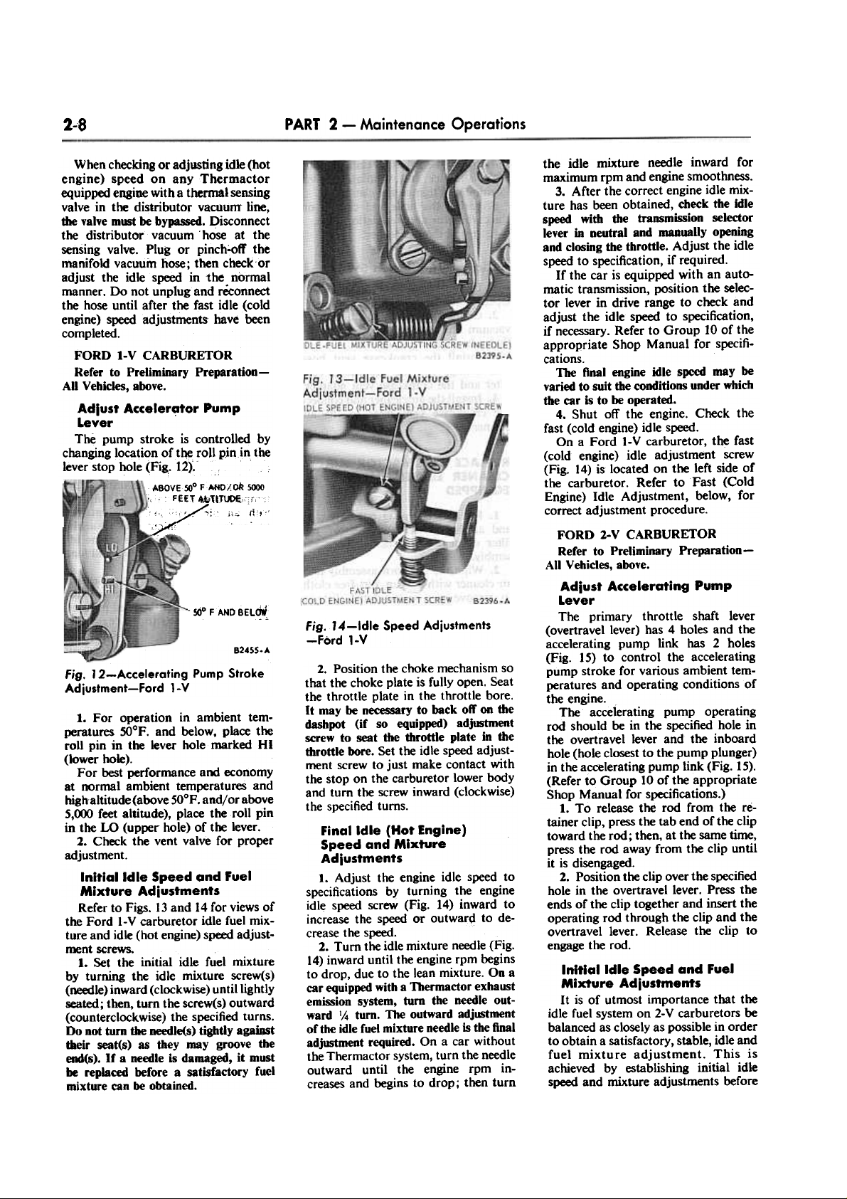
Adiust Accelerator Pump
Lever
The pump stroke is controlled by
changing location oft~ roll p,inin the
lever stop hole (Fig,. 12).
A80VESOO FAHDAoR 5000
" : FEE.'\" ~11~"~r'
:,:~:c i~C;_~!
/
560 FAND BEL~
Fig. J 4-ldle Speed Adjustments
-Ford 1-V
B24SS.A
Fig. 12-Accelerating Pump Stroke
Adjustment-Ford 1-V
2. Position the choke mechanism so
that the choke plate is fully open. Seat
the throttle plate in the throttle bore.
It may be necessary to back oft' on the
dasbpot (if so equipped) adjIWtment
screw to seat the throttle plate in the
throttle bore. Set the idle speed adjustment screw to just make contact with
the stop on the carburetor lower body
and turn the screw inward (clockwise)
the specified turns.
Final Idle (Hot Engine)
Speed and Mixture
Adiustments
1. Adjust the engine idle speed to
specifications by turning the engine
idle speed screw (Fig. 14) inward to
increase the speed or outwar(i to de-
crease the speed.
2. Turn the idle mixture needle (Fig.
14) inward until the engine rpm begins
to drop, due to the lean mixture. On a
car equipped with a Thermactor exhaust
emission system, turn the needle out-
ward 1/4 turn. The outward adj~nt
of the idle fuel mixture needle is the final
adjIWtment required. On a car without
the Thermactor system, turn the needle
outward until the engine rpm increases and begins to drop; then turn
1. For operation in ambient temperatures SOoF. and below, place the
roll pin in the lever hole marked HI
(lower hole).
For best performance and economy
at normal ambient temperatures and
high altitude (above 50oP. and/or above
5,()X) feet altitude), place the roll pin
in the W (upper hole) of the lever.
2. Check the vent valve for proper
adjustment.
Initial Idle Speed and Fuel
Mixture Adiustments
Refer to Figs. 13 and 14 for views of
the Ford I-V carburetor idle fuel mixture and idle (hot engine) speed adjustment screws.
1. Set the initial idle fuel mixture
by turning the idle mixture screw(s)
(needle) inward (clockwise) until lightly
seated; then, turn the screw(s) outward
(counterclockwise) the specified turns.
Do not turn die needle(s) tightly aga~t
their seat(s) as they may groove the
eIMI(s). If a needle is damaged, it must
be replaced before a satisfactory fuel
mixture can be obtained.
the idle mixture needle inward for
maximum rpm and engine smoothness.
3. After the correct engine idle mixture has been obtained, check the idle
speed with the transmission selector
lever in neutral and manually opening
and closing the throttle. Adjust the idle
speed to specification, if required.
If the car is equipped with an automatic transmission, position the selector lever in drive range to check and
adjust the idle speed to specification,
if necessary. Refer to Group 10 of the
appropriate Shop Manual for specifications.
The final engine idle s~ may be
varied to suit the conditions under which
the car is to be operated.
4. Shut off the engine. Check the
fast (cold engine) idle speed.
On a Ford I-V carburetor, the fast
(cold engine) idle adjustment screw
(Fig. 14) is located on the left side of
the carburetor. Refer to Fast (Cold
Engine) Idle Adjustment, below, for
correct adjustment procedure.
FORD 2-V CARBURETOR
Refer to Preliminary Preparation-
All Vehicles, above.
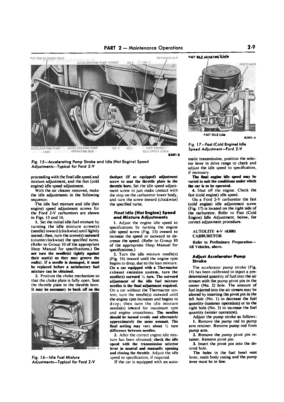
Adiust Accelerating Pump
Lever
The primary throttle shaft lever
(overtravellever) has 4 holes and the
accelerating pump link has 2 holes
(Fig. 15) to control the accelerating
pump stroke for various ambient temperatures and operating conditions of
the engine.
The accelerating pump operating
rod should be in the specified hole in
the overt ravel lever and the inboard
hole (hole closest to the pump plunger)
in the accelerating pump link (Fig. 15).
(Refer to Group 10 of the appropriate
Shop Manual for specifications.)
1. To release the rod from the re-
tainer clip, press the tab end of the clip
toward the rod; then, at the same time,
press the rod away from the clip until
it is disengaged.
2. Position the clip over the specified
hole in the overtravel lever. Press the
ends of the clip together and insert the
operating rod through the clip and the
overtravel lever. Release the clip to
engage the rod.
Initial Idle Speed and Fuel
Mixture Adiustments
It is of utmost importance that the
idle fuel system on 2-V carburetors be
balanced as closely as possible in order
to obtain a satisfactory, stable, idle and
fuel mixture adjustment. This is
achieved by establishing initial idle
speed and mixture adjustments before
Page 14
2-9
PART 2 - Maintenance Operations
FAST ~o~~"I~ '~E'I
FAST I1)LE tAM
82595..
Fig. '7 -Fast (Cold Engine) Idle
Speed Adjustment-Ford 2-V
8~1.8
Fig. 15-Accelerating Pump Stroke and Idle (Hot Engine) Speed
Adjustments-Typical for Ford 2-V
dashpot (if so equipped) adjustment
screw to seat the throttle plate in tile
throttle bore. Set the idle speed adjustment screw to just make contact with
the stop on the carburetor lower body,
and turn the screw inward (clocKwise)
the specified turns.
matic transmission, position the selector lever in drive range to check and
adjust the idle speed to specification,
if necessary.
The hi engine idle speed a.y be
varied to suit the conditions under which
tile car is to be operated.
4. Shut off the engine. Check the
fast (cold engine) idle speed.
On a Ford 2-V carburetor the fast
(cold engine) idle adjustment screw
(Fig. 17) is located on the right side or
t~ carburetor. Refer to Fast (Cold
Enaine) Idle Adjustment, below, for
correct adjustment procedure.
AUTOLITE 4-V (4300)
CARBURETOR
Refer to Preliminary Preparation-
AU Vehicles, above.
proceeding with the final idle speed and
mixture adjustment. and the fast (cold
engine) idle speed adjustment.
With the air cleaner removed, make
the idle adjustments in the following
sequence:
The idle fuel mixture and idle (hot
engine) speed adjustment screws for
the Ford 2-V carburetors are shown
in Figs. IS and 16.
1. Set the initial idle fuel mixture by
turning the idle mixture screw(s)
(needle) inward (clockwise) until lightly
seated; then, turn the screw(s) outward
(counterclockwise) the specified turns.
(Refer to Group 10 of the appropriate
Shop Manual for specifications.) Do
not turn the needle(s) tightly apjmt
tbeir seat(s) as tbey may groove the
end(s). If a needle is damaged, it must
be replaced before a satisfactory fuel
mixture can be obtained.
2. Position the choke mechanism so
that the choke plate is fully open. Seat
the throttle plate in the throttle bore.
It may be necessary to back oft' on the
Adlust Accelerator Pump
Stroke
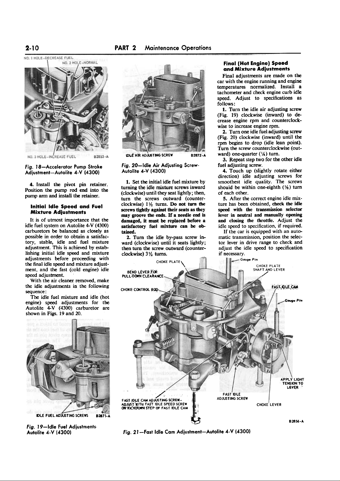
The accelerator pump stroke (Fig.
18) has been calibrated to inject a predetermined quantity of fuel into the air
stream with the pump pivot pin in the
center (No.2) hole. The amount of
fuel injected into the air stream may be
altered by inserting the pivot pin in the
left hole (No. J) to decrease the fuel
quantity (sum~r operation) or to the
right hole (No.3) to increase the fuel
quantity (winter operation).
Adjust the pump stroke as follows:
1. Remove the pump rod to pump
arm retainer. Remove pump rod from
pump arm.
z. Remove the pump pivot pin re-
tainer. Remove pivot pin.
3. Insert the pivot pin into the de-
sired hole.
The holes in the fuel bowl vent
lever. main body casing and the pump
lever must be in line.
Fig. J 6-ldle Fuel Mixture
Adjustments-Typical for Ford 2-V
Final Idle (Hat Engine) Speed
and Mixture Adlustments
1. Adjust the engine idle speed to
specifications by turning the engine
idle speed screw (Fig. 15) inward to
increase the speed or outward to decrease the speed. (Refer to Group 10
of the appropriate Shop Manual for
specifications.)
2. Turn the idle mixture needle(s)
(Fig. 16) inward until the engine rpm
begins to drop, due to the lean mixture.
On a car equipped with a Thermactor
exhaust emission system, turn the
needle(s) outward 14 turn. The outward
adjustment of the idle fuel mixture
needles is the final adjustment required.
On a car without the Therrnactor sys-
tem, turn the needle(s) outward until
the engine rpm increases and begins to
drop; then turn the idle mixture
needle(s) i~ard for maximum rpm
and engine smoothness. The needles
should be turned evenly and alternately
approximately the same amount. The
final setting may vary about 1/2 turn
difference between needles.
3. After the correct engine idle mixture has been obtained, check the idle
speed with the transmission selector
lever in neutral and manually opening
and closing the throttle. Adjust the idle
speed to specification, if required.
If the car is equipped with an auto-
Page 15
2-10
PART 2 Maintenance Operations
IDt.tAIR ADJUSTING SCREW
82872.,A
Fig. 20-ldle Air Adjusting Screw-
Autolite 4-V (4300)
Fig. J 8-Accelerator Pump Stroke
Adjustment-Autolite 4-V (4300)
4. Install the pivot pin retainer.
Position the pump rod end into the
pump arm and install the retainer.
1. Set the initial idle fuel mixture by
turning the idle mixture screws inward
(clockwise) until they seat lightly; then,
turn the screws outward (counter-
clockwise) llh turns. Do not turn die
screws tightly against their seats as they
may groove the ends. If a needle end is
damaged, it must be replaced before a
satisfactory fuel mixture can be obtained.
2. Turn the idle by-pass screw inward (clockwise) until it seats lightly;
then turn the screw outward (counter-
clockwise) 3lh turns.
CHOKE PLATE\
Final (Hat Engine) Speed
and Mixture Adjustments
Final adjustments are made on the
car with the engine running and engine
temperatures normalized. Install a
tachometer and check engine curb idle
speed. Adjust to specifications as
follows :
1. Turn the idle air adjusting screw
(Fig. 19) clockwise (inward) to decrease engine rpm and counterclockwise to increase engine rpm.
2. Turn one idle fuel adjusting screw
(Fig. 20) clockwise (inward) until the
rpm begins to drop (idle lean point).
Turn the screw counterclockwise (outward) one-quarter (II.) turn.
3. Repeat step two for the other idle
fuel adjusting screw.
4. Touch up (slightly rotate either
direction) idle adjusting screws for
smoothest idle quality. The screws
should be within one-eighth (lis) turn
of each other.
5. After the correct engine idle mix-
ture has been obtained, check the idle
speed with the trammission selector
lever in neutral and manually opening
and closing the throttle. Adjust the
idle speed to specification, if required.
If the car is equipped with an automatic transmission, position the selector lever in drive range to check and
adjust the idle speed to specification
if necessary.
Gau~ Pin
CHOKE PLATE
SHAFT AND LEVER
../'
BEND LEVE~f:OO
PuLL-UCJfN tLEARAI-K:E
fA~.i)i9~~~
CHOKE CONTROL R~.
Initial Idle Speed and Fuel
Mixture Adjustments
It is of utmost importance that the
idle fuel system on Autolite 4-V (4300)
carburetors be balanced as closely as
possible in order to obtain a satisfactory, stable, idle and fuel miXture
adjustment. This is achieved by establishing initial idle speed and miXture
adjustments before proceeding with
the final idle speed and miXture adjustment, and the fast (cold engine) idle
speed adjustment.
With the air cleaner removed, make
the idle adjustments in the following
sequence:
The idle fuel mixture and idle (hot
engine) speed adjustments for the
Autolite 4-V (4300) carburetor are
shown in Figs. 19 and 20.
G""fe PIn
APPLY LIGHT
TENSIOOTO
L~VER'
~
/
EA,$~ IDJ;.f' ~ APWSTJNGSC.RE~-
AQ~\JST WITI;\ F~ IDLE SPEED SCREW
cJt'"«tC1<tJowN $YEP OF FAST IDLE CAM
FAST IDLE
ADJ~TING SCREW
CHOKE LEVER
j
;}
~
DLEFfJEL AD"JUSTING SCREWS
82871:-'
82856.A
Fig. 19-1dle Fuel Adjustments.
Autolite 4- V (4300)
Fig. 21 -Fast Idle Cam Adjustment-Autolite 4-V (43001
Page 16
PART 2 2
Maintenance Operations
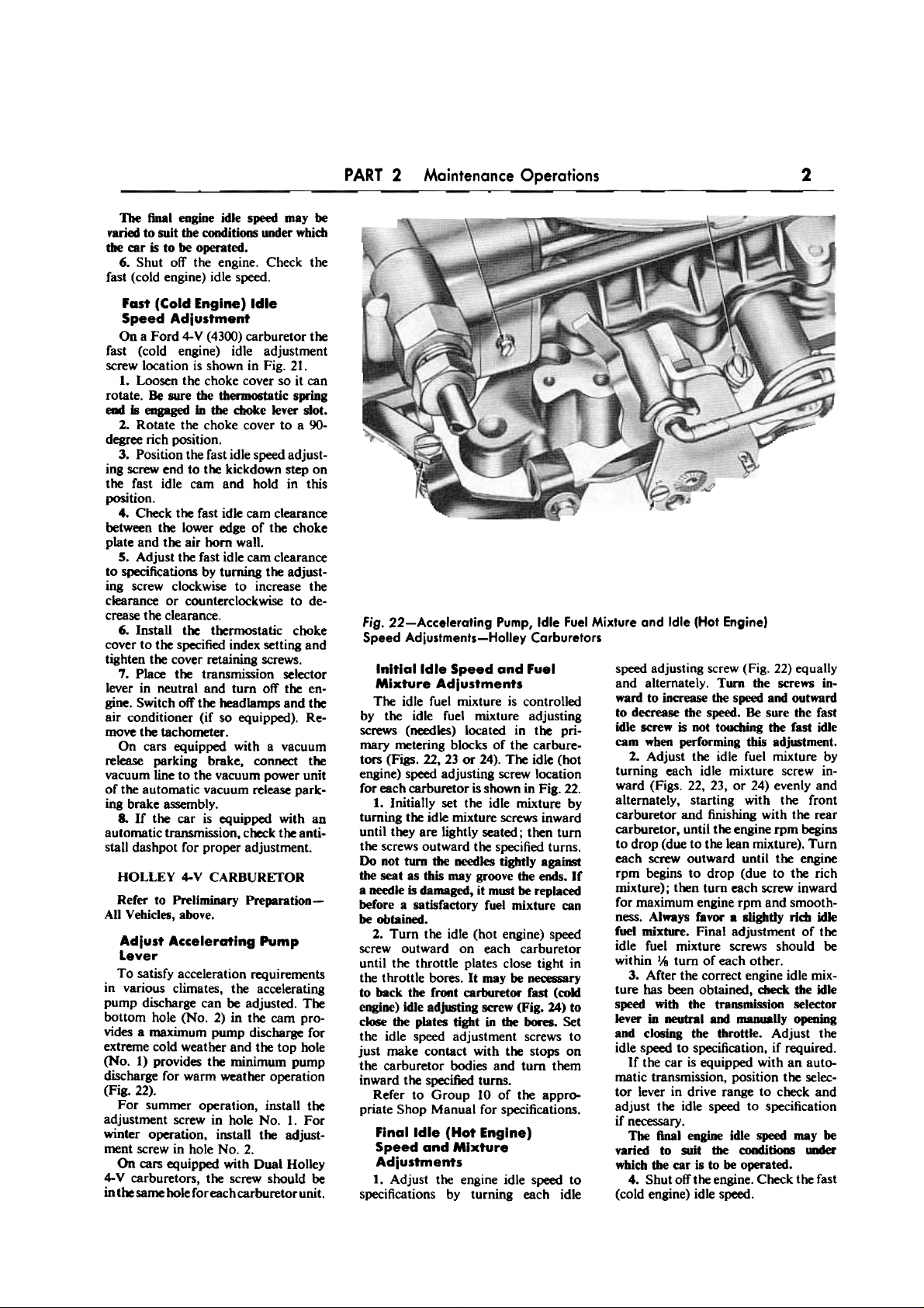
Fig. 22-Accelerating Pump, Idle Fuel Mixture and Idle (Hot Engine)
Speed Adjustments-Holley Carburetors
The final engine idle speed may be
varied to suit the conditions under whim
tbe car is to be operated.
6. Shut off the engine. Check the
fast (cold engine) idle speed.
Fast (Cold Engine) Idle
Speed Adlustment
On a Ford 4-V (4300) carburetor the
fast (cold engine) idle adjustment
screw location is shown in Fig. 21.
I. Loosen the choke cover so it can
rotate. Be sure the thermostatic spring
elM! Is engaged in tbe choke lever slot.
2. Rotate the choke cover to a 90-
degree rich position.
3. Position the fast idle speed adjust-
ing screw end to the kickdown step on
the fast idle cam and hold in this
position.
4. Check the fast idle cam clearance
between the lower edge of the choke
plate and the air horn wall.
S. Adjust the fast idle cam clearance
to specifications by turning the adjusting screw clockwise to increase the
clearance or counterclockwise to decrease the clearance.
6. Install the thermostatic choke
cover to the specified index setting and
tighten the cover retaining screws.
7. Place the transmission selector
lever in neutral and turn off the en-
gine. Switch off the headlarnps and the
air conditioner (if so equipped). Re-
move the tachometer.
On cars equipped with a vacuum
release parking brake, connect the
vacuum line to the vacuum power unit
of the automatic vacuum release parking brake assembly.
8. If the car is equipped with an
automatic transmission, check the antistall dashpot for proper adjustment.
speed adjusting screw (Fig. 22) equally
and alternately. Turn the screws inward to increase the speed and outward
to decrease the speed. Be sure the fast
idle screw is not toudling the fast idle
cam when performing this adj~tment.
2. Adjust the idle fuel mixture by
turning each idle miJcture screw inward (Figs. 22, 23, or 24) evenly and
alternately, starting with the front
carburetor and finishing with the rear
carburetor, until the engine rpm begins
to drop (due to the lean mixture). Turn
each screw outward until t~ engine
rpm begins to drop (due to the rich
mixture); t~n turn each screw inward
for maximum engine rpm and smoothness. Always favor. slightly rid! idle
fuel mixture. Final adjustment of the
idle fuel mixture screws should be
within lis turn of each other.
3. After the correct engine idle mixture has been obtained, dleck the idle
speed with the transmission selector
lever in neutral and manually opening
and cl~ing the throttle. Adjust the
idle speed to specification, if required.
If the car is equipped with an auto-
matic transmission, position the selec-
tor lever in drive range to check and
adjust the idle speed to specification
if necessary.
The final engine idle speed may be
varied to suit the cooditions UIMler
which the car is to be operated.
4. Shut off the engine. Check the fast
(cold engine) idle speed.
HOLLEY ~V CARBURETOR
Refer to Preliminary PrelNlrBtion-
All Vehicles, above.
Adjust Accelerating Pump
Lever
To satisfy acceleration requirements
in various climates, the accelerating
pump discharge can be adjusted. The
bottom hole (No.2) in the cam pro-
vides a maximum pump discharge for
extreme cold weather and the top hole
(No.1) provides the minimum pump
discharge for warm weather operation
(Fig. 22).
For summer operation, install the
adjustment screw in hole No. I. For
winter operation, install the adjust-
ment screw in hole No.2.
On cars equipped with Dual Holley
~ V carburetors, the screw should be
int~same hole for each carburetor unit.
Initial Idle Speed and Fuel
Mixture Adlustments
The idle fuel mixture is controlled
by the idle fuel mixture adjusting
screws (needles) located in the primary metering blocks of the carburetors (Figs. 22, 23 or 24). The idle (hot
engine) speed adjusting screw location
for each carburetor is shown in Fig. 22.
1. Initially set the idle mixture by
turning the idle mixture screws inward
until they are lightly seated; then turn
the screws outward the specified turns.
Do not turn the needles tightly against
the seat as this may groove the ends. If
a needle is damaged, it mmt be replaced
before a satisfactory fuel mixture can
be obtained.
2. Turn the idle (hot engine) speed
screw outward on each carburetor
until the throttle plates close tight in
the throttle bores. It may be necessary
to back the front carburetor fast (cold
engine) idle adjusting screw (Fig. 24) to
close the plates tight in the bores. Set
the idle speed adjustment screws to
just make contact with the stops on
the carburetor bodies and turn them
inward the specified turns.
Refer to Group 10 of the appro-
priate Shop Manual for specifications.
Final Idle (Hot Engine)
Speed and Mixture
Adjustments
1. Adjust the engine idle speed to
specifications by turning each idle
Page 17
2-12
PART 2 - Maintenance Operations
SeCONDARY
CARBURETOR ROO
IDLE MIXTURE SCREW
PRIMARY eARBURETOR
ACCELERATIIK; PlMP
LEVER ADJUSTING SCREW
'SEC(WC)ARY
PRIMARY
: LEVER
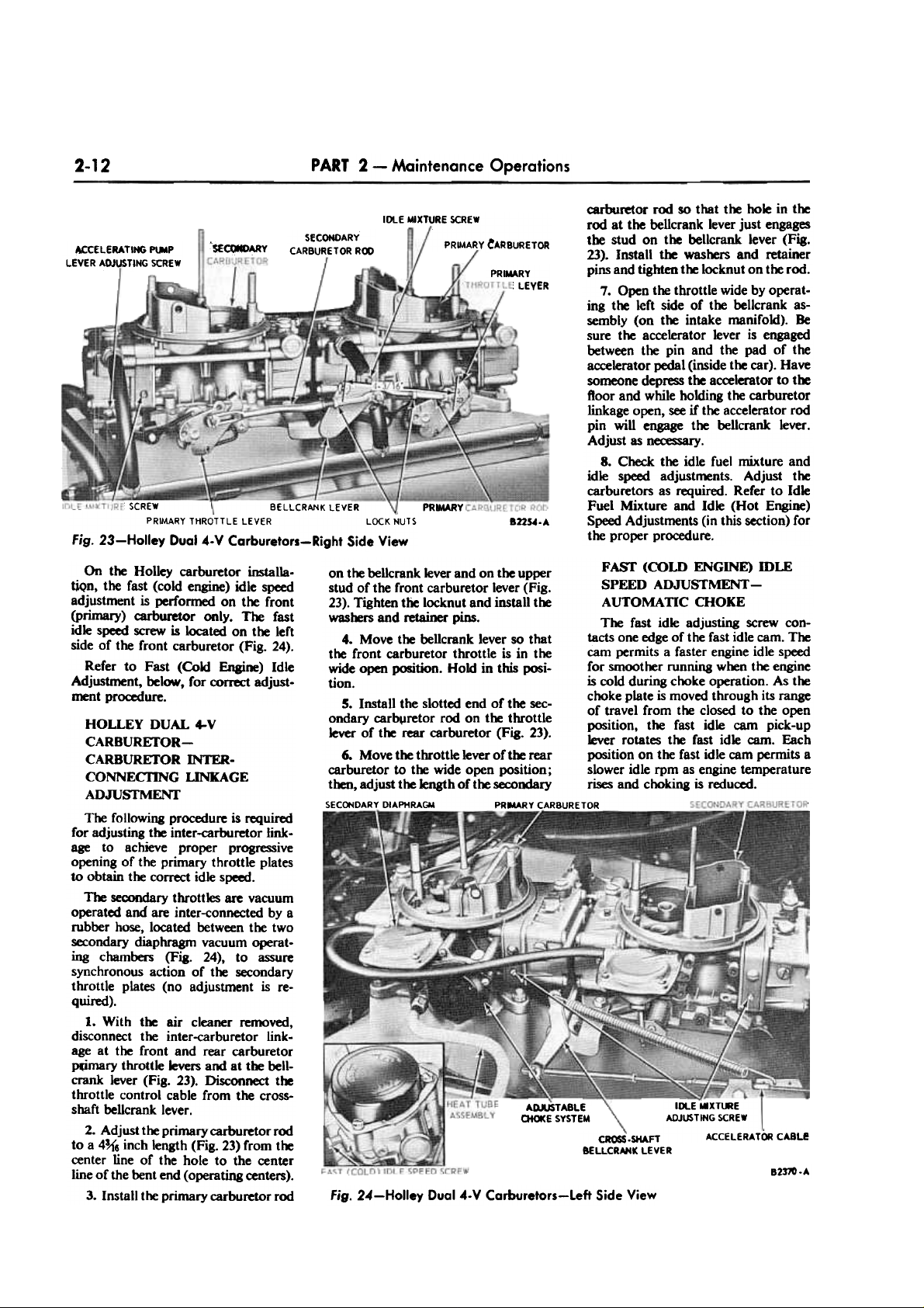
carburetor rod so that the hole in the
rod at the bellcrank lever just engages
the stud on the bellcrank lever (Fig.
23). Install the washers and retainer
pins and tighten the locknut on the rod.
7. Open the throttle wide by operating the left side of the bellcrank assembly (on the intake manifold). Be
sure the accelerator lever is engaged
between the pin and the pad of the
accelerator pedal (inside the car). Have
someone depress the accelerator to the
Roor and while holding the carburetor
linkage open, see if the accelerator rod
pin will engage the bellcrank lever.
Adjust as necessary.
8. Check the idle fuel mixture and
idle speed adjustments. Adjust the
carburetors as required. Refer to Idle
Fuel Mixture and Idle (Hot Engine)
Speed Adjustments (in this section) for
the proper procedure.
PRNARY
SCREW - BELLCRANK LEVER
PRIMARY THROTTLE LEVER LOCK NUTS
Fig. 23-Holley Dual 4-V Carburetors-Right Side View
82254-A
on the bellcrank lever and on the upper FASf (COLD ENGINE) mLE
stud of the front carburetor lever (Fig. SPEED ADJUSTMENT-
23). Tighten the locknut and install t~ AUTOMATIC CHOKE
was~ and retainer pins.
The " .dle d. .
last I a JusUng screw con-
4. Move the bellcrank lever so that tacts one edge of the fast idle cam. The
the front carburetor throttle is in the cam permits a faster engine idle speed
wide open position. Hold in this posi- for smoother running when the engine
tion. is cold during choke operation. As t~
S. Install the slotted end of the sec- choke plate is moved through its range
ondary carb~retor rod on t~ throttle of t.~vel from the c)osed to the. open
lever of the rear carburetor (Fig. 23). posItion, the fast ld~ cam pIck-up
lever rotates t~ fast Idle cam. Each
6. Move the throttle lever of t~ rear position on the fast idle cam permits a
carburetor to t~ wide open position; slower idle rpm as engine temperature
then, adjust the length of t~ secondary rises and choking is reduced.
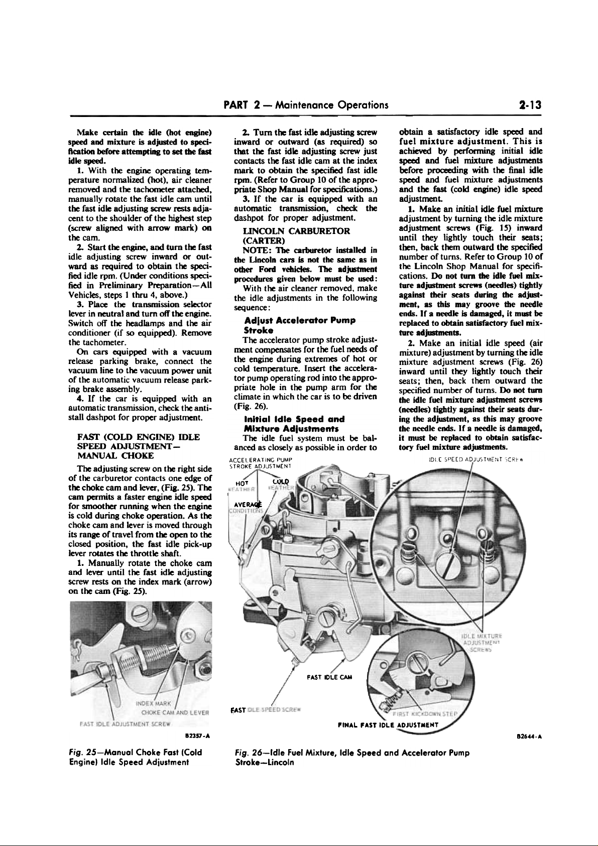
SECONDARY DIAPHRAGM PR~RY CARBURETOR .
On the Holley carburetor instaUatiQn, the fast (cold engine) idle speed
adjustment is performed on the front
(primary) carburetor only. The fast
idle speed screw is located on the left
side of the front carburetor (Fig. 24).
Refer to Fast (CokJ Engine) Idle
Adjustment, below, for correct adjust-
ment procedure.
ADAJSTABLE
OiOICE SYSTEM
HOLLEY DUAL 4-V
CARBUREfOR-
CARBURETOR INTER-
CONNECI1NG UNKAGE
ADJUSTMENf
~ following procedure is required
for adjusting tre inter-carburetor linkage to achieve proper progressive
opening of the primary throttle plates
to obtain the correct idle speed.
~ secondary throttles are vacuum
operated and are inter-connected by a
rubber hose, located between the two
secondary diaphragm vacuum operating chambers (Fig. 24), to assure
synchronous action of tre secondary
throttle plates (no adjustment is re-
q uired).
1. With tre air cleaner removed,
disconnect the inter-carburetor link-
age at the front and rear carburetor
~ry throttle levers and at tre bell-
crank lever (Fig. 23). Disconnect tre
throttle control cable from the crossshaft beUcrank lever.
2. Adjust the primary carburetor rod
to a 4~6 inch length (Fig. 23) from tre
center line of the hole to the center
line of the bent end (operating centers).
3. Install t~ primary carburetor rod
- -.
IDl..E "X~E
ADJUSTING SCREW
ca.SHAFT ACCELERATOR CABLe
8ELLCRMK LEVER
82m-.
Fig. 24-Holley Dua14-V Corburetors-Left Side View
Page 18
2-13
PART 2 - Maintenance Operations
obtain a satisfactory idle speed and
fuel mixture adjustment. This is
achieved by performing initial idle
speed and fuel mixture adjustments
before proceeding with the final idle
speed and fuel mixture adjustments
and the fast (cold engine) idle speed
adjustment.
1. Make an initial idle fuel mixture
adjustment by turning the idle mixture
adjustment screws (Fig. I S) inward
until they lightly touch their seats;
then, back them outward the specified
number of turns. Refer to Group 10 of
the Lincoln Shop Manual for specifications. Do not turn the idle fuel mixture adjtfitment screws (needles) tightly
against their seats during tbe adjust-
ment, as this may groove the needle
ends. If a needle is damaged, it must be
replaced to obtain satisfactory fuel mix-
ture adjustlnellts.
2. Make an initial idle speed (air
mixture) adjustment by turning the idle
mixture adjustment screws (Fig. 26)
inward until they lightly touch their
seats; then, back them outward the
specified number of turns. Do DOt turn
tbe idle fuel mixture adjustment screws
(needles) tightiy agaiMt their seats during the adjustment, as this may groove
the needle euds. If a needle is damaged,
it must be replaced to obtain satisfactory fuel mixture adjustments.
IDlE 5f'EE[} ADJ'JST'~Er~T "CRI-O
Make certain the idle (hot engine)
speed and mixture is adjusted to speciftcatioo before attempting to set the fast
idle speed.
1. With the engine operating temperature normalized (hot), air cleaner
removed and the tachometer attached,
manually rotate the fast idle cam until
the fast idle adjusting screw rests adjacent to the shoulder of the highest step
(screw aligned with arrow mark) 00
the cam.
2. Start the engine. and turn the fast
idle adjusting screw inward or outward as required to obtain the specified idle rpm. (Under conditions specified in Preliminary Preparation-All
Vehicles, steps 1 thru 4, above.)
3. Place the transnrission selector
lever in neutral and turn off the engine.
Switch off the headlamps and the air
conditioner (if so equipped). Remove
the tachometer.
On cars equipped with a vacuum
release parking brake, connect the
vacuum line to the vacuum power unit
of the automatic vacuum release parking brake assembly.
4. If the car is equipped with an
automatic transmission, check the antistall dashpot for proper adjustment.
2.. Turn tlK: fast idle adjusting screw
inward or outward (as required) so
that tlK: fast idle adjusting screw just
contacts tlK: fast idle cam at the index
mark to obtain tlK: specified fast idle
rpm. (Refer to Group 10 of the appropriate Soop Manual for specifications.)
3. If the car is equipped with an
automatic transmission. check the
dashpot for proper adjustment.
LINCOLN CARBURETOR
(CARTER)
NOTE: The carburetor installed in
the Uncoln cars is not the same as in
other Ford vehides. The adjt8tment
procedures given below must be used:
With the air cleaner removed. make
the idle adjustments in the following
sequence:
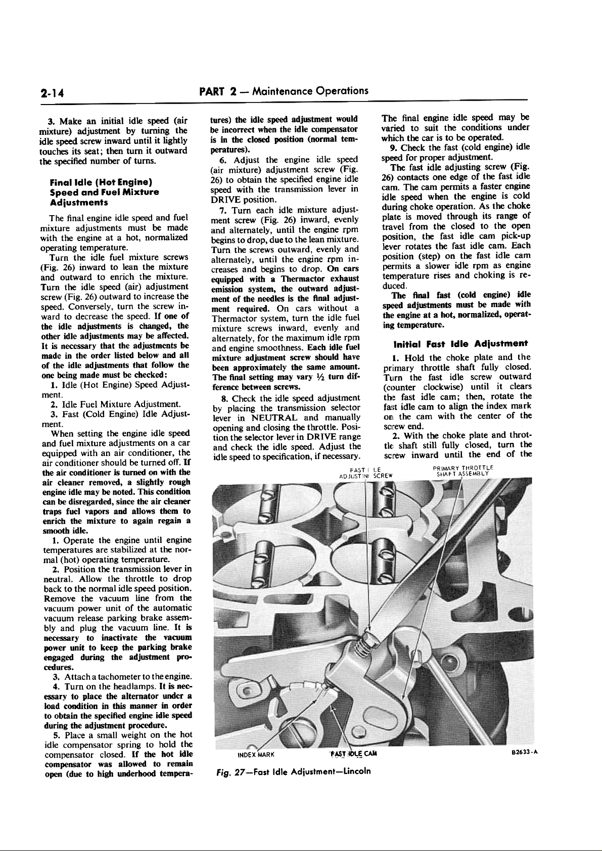
Adlust Accelerator Pump
Stroke
The accelerator pump stroke adjustment compe~tes for the fuel needs of
the engine during extremes of hot or
cold temperature. Insert the accelerator pump operating rod into the appropriate hole in the pump arm for the
climate in which the car is to be driven
(Fig. 26).
Initial Idle Speed and
Mixture Adlustments
The idie fuel system must be balanced as closely as possible in order to
ACCELERATING PUMP
STROKE ADJUS1MENT
FAST (COLD ENGINE) mLE
SPEED AD.JUSTMENTMANUAL CHOKE
The adjusting screw on the right side
of the carburetor contacts one edge of
the choke cam and lever, (Fig. 25). The
cam permits a faster engine idle speed
for smoother running when the engine
is cold during choke operation. As the
choke cam and lever is moved through
its range of travel from the open to the
closed position, the fast idle pick-up
lever rotates the throttle shaft.
1. Manually rotate the choke cam
and le~ until the fast idle adjusting
screw rests on the index mark (arrow)
on the cam (Fig. 25).
(,;~Q
HoT
~veR4
J
FAST IDLE CAM
~ST
PINAL FAST IDLE ADJUSTMENT
82357 .A
Fig. 25-Manual Choke Fast (Cold
Engine) Idle Speed Adjustment
B2644..
fig. 26-ldle fuel Mixture, Idle Speed and Accelerator Pump
Stroke-Lincoln
Page 19
PART 2 - Maintenance Operations
2-14
3. Make an initial idle speed (air
mixture) adjustment by turning the
idle speed screw inward until it lightly
touches its seat; then turn it outward
the specified number of turns.
tures) the idle speed adjustment would
be incorrect when the idle compensator
is in the closed position (normal tem-
peratures).
6. Adjust the engine idle speed
(air mixture) adjustment screw (Fig.
26) to obtain the specified engine idle
speed with the transmission lever in
DRIVE position.
7. Turn each idle mixture adjust-
ment screw (Fig. 26) inward, evenly
and alternately, until the engine rpm
begins to drop, due to the lean mixture.
Turn the screws outward, evenly and
alternately, until the engine rpm increases and begins to drop. On cars
equipped with a Thermactor exhaust
emission system, the outward adjustment of the needles is the final adjustment required. On cars without a
Thermactor system, turn the idle fuel
mixture screws inward, evenly and
alternately, for the maximum idle rpm
and engine smoothness. Each idle fuel
mixture adjustment screw should have
been approximately the same amount.
The final setting may vary 1/2 turn dif-
ference between screws.
8. Check the idle speed adjustment
by placing the transmission selector
lever in NEUTRAL and manually
opening and closing the throttle. Position the selector lever in DRIVE range
and check the idle speed. Adjust the
idle speed to specification, if necessary .
FAST I
ADJUSTIN(
Initial Fast Idle Adiustment
1. Hold the choke plate and the
imary throttle shaft fully closed.
1m the fast idle screw outward
)unter clockwise) until it clears
~ fast idle cam; then, rotate the
;t idle cam to align the index mark
l the cam with the center of the
rew end.
2. With the choke plate and throt: shaft still fully closed, turn the
rew inward until the end of the
PRIMARY THROTTLE
SHAfT ASSEMBLY
Final Idle (Hot Engine)
Speed and Fuel Mixture
Adjustments
The final engine idle speed and fuel
mixture adjustments must be made
with the engine at a hot, normalized
operating temperature.
Turn the idle fuel mixture screws
(Fig. 26) inward to lean the mixture
and outward to enrich the mixture.
Turn the idle speed (air) adjustment
screw (Fig. 26) outward to increase the
speed. Conversely, turn the screw inward to decrease the speed. If one of
the idle adjustments is changed, the
other idle adjustments may be affected.
It is necessary that the adjustments be
made in the order listed below and all
of the idle adjustments that follow the
one being made must be checked:
1. Idle (Hot Engine) Speed Adjust-
ment.
2. Idle Fuel Mixture Adjustment.
3. Fast (Cold Engine) Idle Adjust-
ment.
When setting the engine idle speed
and fuel mixture adjustments on a car
equipped with an air conditioner, the
air conditioner should be turned off. If
the air conditioner is turned on with the
air cleaner removed, a slightly rough
engine idle may be noted. This condition
can be disregarded, since the air cleaner
traps fuel vapors and allows them to
enrich the mixture to again regain a
smooth idle.
1. Operate the engine until engine
temperatures are stabilized at the normal (hot) operating temperature.
2. Position the transmission lever in
neutral. Allow the throttle to drop
back to the normal idle speed position.
Remove the vacuum line from the
vacuum power unit of the automatic
vacuum release parking brake assemblyand plug the vacuum line. It is
necessary to inactivate the vacuum
power unit to keep the parking brake
engaged during the adjustment procedures.
3. Attach a tachometer to the engine.
4. Turn on the head lamps. It is necessary to place the alternator under a
load condition in this manner in order
to obtain the specified engine idle speed
during the adjustment procedure.
5. Place a small weight on the hot
idle compensator spring to hold the
compensator closed. If the hot idle
compensator was allowed to remain
open (due to high underhood tempera-
B2633.A
f~J~~ cAJA
INDEX MARK
Fig. 27 -Fast Idle Adjustment-Lincoln
The final engine idle speed may be
varied to suit the conditions under
which the car is to be operated.
9. Check the fast (cold engine) idle
speed for proper adjustment.
The fast idle adjusting screw (Fig.
26) contacts one edge of the fast idle
cam. The cam permits a faster engine
idle speed when the engine is cold
during choke operation. As the choke
plate is moved through its range of
travel from the closed to the open
position, the fast idle cam pick-up
lever rotates the fast idle cam. Each
position (step) on the fast idle cam
permits a slower idle rpm as engine
temperature rises and choking is re-
duced.
The final fast (cold engine) idle
speed adjmtments must be made with
the engine at a hot, normalized, operat-
ing temperature.
pc
Tl
(c(
tho
fa!
011
SCI
tIe
sc
LE
SCREW
Page 20

PART 2 - Maintenance Operations
2-15
CONDITION
CAUSED BY
Any discoloration other than a frosted slate
grey shall be considered as rorned points.
BURNED
Incorrect alignment.
Incorrect voltage regulator setting.
Radio condenser installed to the distributor
side of the coiL
Ignition condenser of improper capacity.
Extended operation of the engine at speeds
other than normaL
EXCESSIVE MnAL
I TRANSFER OR PInING
81443-8
Fig. 28-Breaker Point Inspection
4. Repeat this procedure until speci-
fied dwell is obtained.
If new points are installed, set
the gap to specifications using a
feeler gauge.
~
CONTACT
AR!A
C8'nERED
~-t
CORRECT
ALIGNMENT
81019-A
Fig- 29-Breaker Point Alignment
Guide
Too/-KO.111 or TK.419.A
screw just touches the cam at the
index mark (Fig. 27). Release the
throttle shaft and turn the fast idle
screw inward one full turn.
Final Fast Idle Adiustment
Make certain the idle (hot engine)
speed alMl mixture is adjmted to
specification before attempting to set
the ftD81 fast idle speed.
1. With the engine at a stabilized
normal operating temperature, tachometer installed, headlamps turned
on, idle compensator closed, P8rkinI
brake on and the transmission selector
lever in NEUTRAL; position the fast
idle screw on the first kickdoWD step
(Fig. 26). located next to the highest
(index marked) step on the fast idle
cam. Adjust the fast idle screw to
obtain the specified fast idle rpm.
2. Turn off the engine. Remove
the tachometer. Remove the weight
from the bot idle compensator. Turn
off the headlamps. Connect the vacuum line to the vacuum power unit of
the vacuum release parking brake
assembly.
3. Check the anti-stall dashpot and
accelerating pump for proper adjustment. Install the air cleaner assembly.
LUBRICATE ACCELERATOR
BALL SOCK"S AND
CARBURETOR LEVER KICKDOWN ACTUATING CAM
-ECONOLINE AND BRONCO
Lubricate the accelerator pedal shaft
and kickdown actuating cam on all
engines. When equipped with auto-
matic transmission, lubricate all friction points in the accelerator to
carburetor linkage with specified lubricant.
CHECK DISTRIBUTOR POINTS
AND ADJUST DWELL
Unsnap the distributor cap retain-
ing clips, lift the distributor cap off
the distributor housing, and position
the cap out of the way (if necessary,
remove the air cleaner and/or the
high tension wire to gain access to
the distributor).
Lift the rotor off the cam. Remove
the dust cover (transistorized ignition).
BREAKER POINT INSPEC110N
Breaker points should be inspected,
cleaned and adjusted as necessary.
Breaker points can be cleaned with
chloroform and a stiff bristle brush.
Caution: Make sure there Is te
ventiJatiCMa. Replace the breaker point
assembly if the contacts are badly
burned or excessive metal transfer
between the points is evident (Fig. 28).
BEND STATIONARY BRACKET B2351.A
Fig. 30-Aligning Breaker PointsTypical
Metal transfer is considered excessive
when it equals or exceeds the gap
setting.
BREAKER POINT AUGNMENT
The vented-type breaker points
used in Ford distributors must be
accurately aligned in order to realize
the full advantages provided by this
design, and to assure normal breaker
point life. Any misalignment of the
breaker point surfaces will cause pre-
mature wear, overheating, and pitting.
1. Turn the distributor cam so
that the breaker points are closed and
check the alignment of the points
(Fig. 29).
1. Align the breaker points to make
full face contact by bending the
stationary breaker point bracket (Fig.
30). Do not bend the breaker arm.
3. After the breaker points have
been properly aligned, adjust the
breaker point gap or dwell.
DWELL ANGLE ADJUSTMENT
Use a dwell meter to check the
contact dwell. It is not advisable to
use a feeler gauge to adjust or to
check the gap of used breaker points
because the roughness of the points
makes an accurate gap reading or
setting impossible.
If the I8ed points are serviceable, set
the gap using a dwell meter as follows:
1. Connect the dwell meter following the manufacturer's instructions.
In a car equipped with transistor ignition, make sure that the dwell meter is
connected to the tadlOmeter block
rather than the coil.
1. 0 perate the engine at idle speed
and note the reading on the dwell
meter.
3, Stop the engine and adjust the
gap (decreasing the gap increases the
dwell). Now check the dwell again.
Page 21

2-16
PART 2 - Maintenance Operations
5. Install the dust cover (transis-
torized ignition).
6. Install the ro tor. Install the distributor cap on the distributor housing
and snap the retaining clips in place.
INSPECT, CUAN, ADJUST
AND TEST SPARK PLUGS
REMOVAL
1. Remove the wire from each
spark plug by grasping, twisting and
then pulling the moulded cap of the
wire only. Do not pull on the wire
because the wire connection inside the
cap may become separated or the
weather Ral may be damaged.
1.. Clean the area around each spark
plug port with compressed air, then
remove t~ spark plugs.
CLEANING AND JNSPEcrION
1. Examine t~ firing ends of t~
spark plugs, noting the type of deposits and t~ degree of electrode
erosion. Refer to Fig. 31 for the various types of spark plug fouling and
their causes.
2. Clean t~ plugs on a sand blast
cleaner, following t~ manufacturer's
instructions. Do not prolong the use
of the abrasive blast as it will erode
the iJISuIator. Remove carbon and
other deposits from the threads with
a stiff wire brush. Any deposits will
retard t~ heat flow from the plug
to the cY linder ~ad causing spark
plug overheating and pre-ignition.
3. Oean the electrode surfaces with
a small file (Fig. 32). Dress t~
electrodes to secure flat parallel surfaces on both the center and side
electrode.
4. After cleaning, examine the plug
carefully for cracked or broken insulators. badly pitted electrodes, and
~1.A
Fig. 32-Cleaning Spark Plug
Electrode
Fig. 3 J -Spark Plug Inspection Guide
Page 22

PART 2 - Maintenance Operations
2-17
Fig. 33-Checking Spark Plug Gap
other signs of failure. Replace as
required.
Fig. 36-Typical V-8 Engine Timing
Marks-Except 289
ADJUSTMENT
Set the spark plug gap to specifications by bending the ground electrode.
(Fig. 33). Never bend the center
electrode. (Refer to Group 9 Specifications in the appropriate Shop Manual
for gap settings.)
81474-8
Fig. 34- Typical Six-Cylinder Engine
Timing Marks
TESTING
After the proper gap is obtained,
check the plugs on a testing machine.
Compare the sparking efficiency of
the cleaned and gapped plug with a
new plug. Replace the plug if it fails
to pass the test as outlined in the
tester instruction manual.
Test the plugs for compression
leakage at the insulator seal. Apply
a coating of oil to the shoulder of
the plug where the insulator projects
through the shell, and to the top of
the plug, where the center electrode
and terminal project from the insu-
lator. Place the spark plug under
pressure with the tester's high tension wire removed from the spark
plug. Leakage is indicated by air
bubbling through the oil. If the test
indicates compression leakage, replace the plug. If the plug is satisfactory, wipe it clean.
(BTDC). The crankshaft puUey or
damper has a timing notch.
V -8 Eagines. The crankshaft damper
for the 289 V-8 engine (Fig. 35) has
five timing marks ranging from top
dead center (fDC to 12° before top
dead center (BTDC).
The crankshaft damper for all V-8
engines except the 289 has 15 timing
marks ranging from top dead center
(TDC) to 300 before top dead center
(BTDC) (Fig. 36). Refer to specifications for the correct ignition timing.
INSfALLATlON
1. Install the spark plugs and torque
each plug to 15-20 ft-lbs.
When a new spark plug is installed
in a new replacement cylinder head,
torque the plug to 20-30 ft-lbs.
1. Connect the spark plug wires.
Push all weather seals into position.
CHECK AND ADJUST
IGNlnON TIMING
TL\.fiNG MARK LOCATIONS
Six Cylinder Engines. The timing
pointer (Fig. 34), has five timing
marks ranging from top dead center
(fDC) to 14° before top dead center
Fig. 35-289 V-8 Engine Timing
Marks
DMING PROCEDURE
To check and adjust the timing
with a Rotunda 13-07 power timing
light, proceed as follows:
I. Remove the plug wire from the
number 1 spark plug.
2. Install the spark plug adaptor on
the spark plug.
3. Connect the plug wire to the
spark plug adaptor.
4. Clamp t~ timing light spark
plug lead to the spark plug adaptor.
5. Connect the timing light battery
leads to the battery terminals.
6. Disconnect the distributor vac-
uum line (if so equipped).
7. If necessary, clean and mark the
timing marks.
8. Connect a tachometer to the
engine.
NOTE: When connecting a tachometer to a car equipped with a transistorized ignition, connect the leads
to the tachometer block (positive lead to
red tenninal, negative to black).
9. Start the engine and adjust the
speed to the specified rpm for initial
timing adjustment. Allow the engine
to warm up and point the timing light
at the timing pointer.
10. If the timing is incorrect, loosen
the distributor hold down bolt and
rotate the distributor until the desired
initial advance is obtained.
11. Tighten the distributor hold
down bolt and check the timing again.
12. Turn off the engine.
13. Remove the timing light and
connect the vacuum line.
Page 23

2-18
PART 2 - Maintenance Operations
~.'
~
,...
:nn,
'"
':, ~
i
;:.t
£'.1
'k:i\J:
~
~'
rC;!,;if~", ji ~f --- t 7"f c~ iii ,J ~:-:o:::::::--- ~
"':;~ ~
; !~--~ ~ -"'""F; X
,"CYLINDER ENGINE WITH AUTDMATfC CHOKE
/","
J r II '):::::::J
~~:::; r )~ ,. /
,.,
~::::=J
-::~
/j"'/
-:t:::
"" '
f;' c'
1;:~::.:::::;~~~~:~~:"; -;;.-. ---
/1--
~
~
'Sifj
~/
/
"~
~
~
/
~
~
KI649.A
To drain the radiator, open the
drain cock located at the bottom of
the radiator and remove the cylinder
block drain plug(s). The 6-cylinder
engine block has one drain plug
located at the right rear of the cylinder
block ahead of the starter (Fig. 39).
The V -8 engines have a drain plug on
each side of the cylinder block (Fig.
40).
To fill the cooling system, close the
drain cock. Install the block drain
plug(s). Disconnect the heater outlet
hfJSe at the water pump to bleed or
release trapped air in the system. When
the coolant begins to escape, connect
the heater outlet hose.
DRAIN PLUG
CHECK EXHAUST CONTROL
VALVE FOR FREE OPERATION,
IF SO EQUIPPED
The exhaust control valve, if the
car is so equipped, should be checked
to make certain it is operating properly. A valve that is stuck in the open
position will result in poor engine
performance during initial warm-up,
because the heat passing through the
intake manifold heat riser is insufficient
for proper fuel atomization.
On V-8 engines, if the valve is
stuck in the closed position, the intake manifold will be supplied with
excessive heat after the initial warmup period. This will cause poor acceleration, a lack of power, and will
cause poor high speed performance
in general.
Check the thermostatic spring of
the valve (Fig. 37) to make sure it is
hooked on the stop pin. The spring
stop is at the top of the valve housing
when the valve is properly installed.
To check the exhaust control valve
on the vehicle, make sure the spring
holds the valve closed. Actuate the
counterweight by hand to make sure
it moves freely through approximately
90° of rotation without binding.
The valve is closed when the en-
gine is cold. However, a properly
operating valve will open when very
light finger pressure is applied to
the counterweight. Rapidly acceler-
ate the engine to make sure the valve
momentarily opens. The valve is de-
signed to open when the engine is at
normal operating temperature and is
operated at high rpm.
Lubricate the valve widl Rotunda
Exbamt Control Valve Solvent (COAA-
19A5OI-A.)
CHECK RADIATOR
COOLANT LEVEL
The coolant level should be kept
one inch below the bottom of the
radiator filler neck.
Use care when removing the radio
ator cap to avoid injury from escaping
steam or hot water.
INSPECT COOLING
SYSTEM HOSES AND LINES
-ECONOLINE AND BRONCO
Inspect the cooling system hoses for
evidence of cracking, checking or extreme weathering. Replace cracked
hoses. Check for leaking or porous
hoses and tighten or replace.
Make sure all supporting brackets
for hoses are in place and that the
hoses are properly installed in the
support.
Inspect the radiator core and tanks
for seepage or leaks.
Check all fittings to see that they
are tight and in good condition.
Examine the hoses at the fittings for
cuts or weakness.
REPLACE ENGINE COOLANT
IMPORT ANT: On all 'Vehicles, the
hose connecting the heater water 'Val'Ve
to the intake manifold (this is the hose
that feeds hot water to the heater,
Fig. 38) must be replaced each time
the engine coolant is replaced.
81511-A
Fig. 39- Typical Cylinder Block
Drain Plug-Six
Fig. 37 -Six-Cylinder Engine
Exhaust Control Valve-Typical
Fig. 38-Heater Hose Routings- Typical Six and Eight Cylinder Engines
Page 24

PART 2 - Maintenance Operations
2-19
FUEL FILTER ELEMENT-
42.7 V-8
~ PWG ."H-A
Fig. 40-Typical Cylinder Block
Drain Plug-V-a
The in-line fuel filter for the 427
V -8 engine (Fig. 42) contains a re-
placeable filter element.
I. Unscrew the filter housing from
the fuel filter cover (Fig. 42). Remove
and discard the filter element and
gasket.
1. Clean the filter housing in solvent.
3. Coat a new gasket with light
engine oil and position the gasket on
the filter housing. Position a new filter
clement over the spout on the cover.
Only a filter element displaying installation instructions should be used. Install
the filter element according to the
printed instructions on the element.
4. Screw the filter housing onto the
cover (Fig. 42). Hand tighten the filter
housing until the gasket makes contact with cover; then, advance it lis
turn.
5. Start the engine and check for
fuel leaks.
FUEL FILTER-LINCOLN
A replaceable fuel filter is located
between t~ fuel pump and the carburetor fuel inlet line (Fig. 43).
3. Unscrew the fuel filter from the
carburetor and discard the gasket.
Disconnect the fuel filter from the
hose and discard the retaining clamp.
4. Install a new clamp on the inlet
hose and connect the hose to the
filter. Place a new gasket on the new
fuel filter and screw the filter into the
carburetor inlet port. Tighten the filter.
5. Position the fuel line hose clamp
and crimp the clamp securely.
6. Start the engine and check for
fuel leaks.
7. Install the air cleaner.
FIL
,GASKET-~
Fig- 43-Fuel Filter-Lincoln
- !.TER
ELEMENT-
9635
All coolant added should be a 50-50
mixture of Rotunda permanent antif~ and water.
To avoid possible overheating in
very hot weather, do not use mixtures
with more than 50% anti-f~ except
in areas where anti-freeze protection
below - 35° is required. In this case,
refer to the coolant mixture chart on
the Rotunda permanent anti-f~
container.
Whenever the system is completely
refilled, add a can of Rotunda Radiator Rust Inhibitor.
A standard ethylene glycol hydrometer can be used to check the protection
level of the long-life coolant.
Operate the engine until normal
operating temperature is reached, and
add more coolant, if necessary, to fill
the radiator to the proper level, one
inch below bottom of the radiator
filler neck.
After the initial fill the coolant level
may drop approximately one quart
after the engine has been operated
about 20 minutes at 2(XX) rpm. This
is due to the displacement of entrapped air. Refill to the proper level.
REPLACE FUEL FILTER
OR ELEMENT
FUEL FILTERS-ALL EXCEPT
427 V.8 AND UNCOLN
The in-line fuel filter used on all
engines except the 427 V -8 is of onepiece construction and cannot be
cleaned. Replace the Wter if it becomes
dogged or restricted.
1. Remove the air cleaner.
2. Loosen the retaining clamp securing the fuel inlet hose to the fuel filter
(Fig. 41).
FILTER itooSlNG
1. Disconnect the fuel line from
the filter. Unscrew the filter from the
fuel pump.
2. Screw the new filter ioto the fuel
pump. Do not overtjghten it. Con-
nect the fuel line to the fuel filter. Use
a Wfendl on the fiJter COIIDectiOII to
prevent distorting or damaging the
ftlter case.
3. Operate the engine and check
the fuel line and filter connections for
leaks.
B 2940..
Fig. 42-ln-Line Fuel Filter-427 V-8
Page 25

2-20
PART 2
Maintenance Operations
~ TRANSMISSION
ADJUST AUTOMATIC
TRANSMISSION BAND(S)
Automatic transmissions used in
current production vehicles are varia.
tions of three basic transmissions:
Cruise-O-Matic, or Merc-O-Matic
(referred to as MX-FX in the follow-
ing paragraphs) C6, or C4. As a
guide to band adjustment. Table 1
lists the combination of bands used
in each transmission. For a complete
diagnosis chart of automatic transmission troubles for any vehicle,
refer to Group 7 of the Shop
Manual for that vehicle.
T ABl.E I. Band Arrangement of
Automatic Transmissions.
Fig. 45-Front and Rear Band
Adjusting Tools-FX-MX
Fig. 44-Typical Front Band
Adjustment-MX-FX
MX-FX
justing screw stationary and tighten
the locknut to specifications.
5. Install the transmission fluid
screen. Install the pan, using a new
gasket.
6. Connect the transmission fluid
filler tube to the oil pan.
7. Refill the transmission to the
FULL mark on the dipstick.
8. Stan the engine and engage the
transmission in each drive range to
fill all fluid passages. then place the
selector in the "p" position. Check
the fluid level and add enough fluid
to bring the level up to the FULL
mark on the dipstick.
5. Install the socket handle on the
~6-inch socket.
6. Insert the T -handle extension
through the socket handle and socket. and install the screwdriver socket
on the T -handle extension.
7. Place the tool on the adjusting
screw so that the screwdriver socket
engages the screw and the o/io-inch
socket engages the lo::k nut.
8. With a torque wrench on the
T -handle extension, torque the adjusting screw to 10 in-ibs. Remove
the gauge block. Tighten the adjusting screw an additional ¥4 turn.
9. Hold the adjusting screw stationary, and torque the lock nut to
specification.
10. Place a new gasket on the oil
pan, and install the screen and pan
on the transmission.
11. Connect the filler tube to the
oil pan and tighten the fitting se-
curely.
11. Add 3 quarts of transmission
fluid. Run the engine for 2 minutes.
Place selector lever in P position.
Check the fluid level and add enough
fluid to bring the level up to the
FULL mark on the dipstick.
Rear Band Adlustment
1. Fold back the floor mat to expose the right side of the floor pan.
2. Remove the access hole cover
from the floor pan. Remove all dirt
from the adjusting screw threads,
then oil the threads.
3. Loosen the rear band adjusting
screw lock nut with the tool shown
in Fig. 46. Using the T -handle portion of the tool, tighten the adjusting
screw until the wrench overruns.
If the screw is found to be dghter
than wrench capacity (10 ft-ibs
Alternate Front Band
Adjustment
I. Disconnect the fluid filler tube
from the oil pan, and drain the fluid
from the transmission. If the same
fluid is to be used again in the transmission after the band adjustment,
filter the fluid through a tOO-mesh
screen as it drains from the transmission. Re-use the fluid only if it is in
good condition.
2. Remove and thoroughly clean
the oil pan and screen. Discard the
oil pan gasket.
3. Loosen the front servo adjusting screw locknut two full turns with
a o/ts-inch wrench. Check. the ad.
justing screw for free rotation in the
actuating lever after the lock nut is
loosened, and free the screw if necessary .
4. Pull the adjusting screw end of
the actuating lever away from the
servo body. and insert the 1/4 ff adjust-
ing tool gauge block (Fig. 45) between the servo piston stem and the
adjusting screw.
MX-FX
TRANSMISSION
Front land Adlustment
I. Disconnect the fluid filler tube
from the oil pan, and drain the fluid
from the transmission. If the same
fluid is to be used again in the trans-
mission after the band adjustment,
filter the fluid throu~h a tOO-mesh
screen as it drains from the transmission. Make sure that the container is
clean. Re-use the fluid only if It is in
good condition,
2. Remove and thoroughly clean
the oil pan, then remove the fluid
screen and clip from the transmis-
sion. Clean the inside of the oil pan.
Do not attempt to clean the filter. If
dirty instaJl a new one. Discard the
oil pan gasket. Remove all gasket material from oil pan and pan mounting face of case.
3. Loosen the front servo adjusting screw locknut two full turns.
4. Pull back on the actuating lever,
then insert the Gauge Block, Tool
7225-C13-B, of front band adjusting
Tool 7225-C, (Fig. 44) between the
servo piston stem and adjusting
screw.
Tighten the adjusting screw until
the wrench overruns (this should be
exactly 10 in-lbs). Remove the gauge
block. Tighten the adjusting screw
an additional ¥4 turn. Hold the ad-
Page 26

2-21
PART 2
Maintenance Operations
OW""
- --1001-7195-( 01329-A
fig. 46-Adjusting Rear BandFX-MX
r
torque), loosen the screw and tighten
until the wrench overruns.
4. Back off the adjusting screw
11/2 turns. Hold the adjusting screw
stationary. and tighten the adjusting
screw lock nut to specifications.
Severe damage may result If the
adjustinK screw is not backed off exactly 11/2 turns.
01575-.
Fig. 47 -Console Component Parts-MX-FX
~
Alternate Rear Band
Adlu5tment
The tool shown in Fig. 45 may be
used to adjust the rear band.
I. Place the socket holder on the
¥4 -inch socket (Fig. 45). Insert the
T -handle extension through the handle and socket.
1. Place the "fiG-inch 8-point socket on the extension. Place a torque
wrench on the T -handle extension.
3. Insert the assembled tool in the
access hole so that it engages the adjusting screw and the lock nut.
4. Loosen the adjusting screw lock
nut.
S. Torque the adjusting screw to
10 ft-lbs.
6. Remove the torque wrench
from the T-handle extension and
back off the adjusting screw exactly
1 1/2 turns. Severe damage may re-
sult to the transmission if the adjust-
ing screw is not backed off exactly
II/}. turns.
7. Hold the, : screw sta-
3. Remove and discard the adjustment screw lock nut. Install a new
lock nut on the adjustment screw,
and leave it loose.
4. Tighten the band adjustment
screw as shown in Fig. 48 until the
wrench overruns (this should be ex-
actly 10 ft-Ibs), then back it oil 1
tom.
5. Hold the adjusting screw sta-
tionary and torque the lock nut to
specifications.
6. Lower the car.
C-4 TRANSMISSION
Front (Intermediate) Band
Adjustment
1. Clean all the dirt from the band
adjusting screw area. Remove and
attach the console finish panel casting to the console panel, and remove
the casting (Fig. 47).
4. Remove the four bolts that se-
cure the gear shift indicator to the
support assembly.
5. Remove the twelve screws that
attach the console panel mouldings
to the console panel and remove the
mouldings (Fig. 47).
6. Remove the eight screws that
attach the console panel to the console support assembly.
7. Position the console panel out
of the way and adjust the transmission rear band. Refer to Rear Band
Adjustment, or Alternate Rear Band
Adjustment, above.
8. Install the console panel and
secure to the support assembly with
eight screws.
.9
d the
ldjustinr
OAn thA 1
Rear Band Adlustment
With Cansale
Part of the console assemb
WIll
the
C6 TRANSMISSION
INTERMEDIATE BAND
ADJUSTMENT
1. Raise the car on a hoist
have to be removed to adjust
rear band.
1. Loosen the two forward scn
that attach the glove compartmenl
the console panel.
2. Remove the gear shift Ie
knob.
stands
2. (
Fig. 48-lntermediate Bond
Adjustment-C6 Transmissior
:lean the threads of the inter
te band adjustment screw.
Rem
Page 27

2-22
PART 2 Maintenance Operations
TooI-T59P.77370.8 or 7345.
Econoline and Bronco
Clean dirt and grease from the
breather air vent opening and see
that the opening is clear.
justing screw reaches 10 ft-lbs.
3. Back off the adjusting screw ex-
actly 3 full turns.
4. Hold the adjusting screw from
turning and torque the lock nut to
specification.
LUBRICATE MANUAL
TRANSMISSION SHIFT
CONTROL AND LINKAGE
Clean and lubricate the shift linkage, trunnions and external shift
mechanism (floor shift) as necessary.
Use Lithium base grease. Do not use
Polyethylene Grease for this applica-
tion.
D1460-A
Fig. 49-Front (Intermediate) Band
Adjustment-C4 Transmission
LUBRICATE AUTOMATIC
TRANSMISSION KICKDOWN
LINKAGE
Lubricate all pivot points in the
kickdown linkage with the specified
engine oil.
discard the adjustment screw lock
nut. Install a new lock nut on the adjustment screw, and leave it loose.
2. With the tool shown in Fig. 49,
tighten the adjusting screw until the
tool handle clicks. The tool is a pre-
set torque wrench which clicks and
overruns when the torque on the adjusting screw reaches 10 ft-lbs.
3. Back oft the adjusting screw ex-
acOy 13/4 turns.
4. Hold the adjusting screw from
turning and torque the lock nut to
specification.
Rear (Low-Reverse) Band
Adjustment
1. Clean all the dirt from the band
adjusting screw area. Remove and
discard the adjustment screw lock
nut. Install a new lock nut on the adjustment screw and leave it loose.
2. With the tools shown in Fig. 50,
tighten the adjusting screw until the
tool handle clicks. The tool is a preset torque wrench which clicks and
overruns when the torque on the ad-
CHECK AUTOMATIC
TRANSMISSION FLUID LEVEL
1. Make sure that the car is stand-
ing level. Then firmly apply the park-
ing brake.
2. Run the engine at normal idle
speed. If the transmission fluid is
cold, run the engine at fast idle speed
(about 1200 rpm) until the fluid
reaches its normal operating temperature. When the fluid is warm,
slow the engine down to normal idle
speed.
3. On a car equipped with a vacuum brake release, disconnect the
release line and plug the end of the
line; otherwise the parking brake will
not hold the transmission in any drive
position.
4. Shift the selector lever through
all positions, and place the lever at
P. Do not turn off the engine during
the fluid level checks.
5. Clean all dirt from the transmission fluid dipstick cap before removing the dipstick from the filler
tube.
6. Pull the dipstick out of the tube,
wipe it clean, and push it all the way
back into the tube. Be sure it is prop-
erly seated.
7. Pull the dipstick out of the tube
again, and check the fluid level. If
necessary, add enough fluid to the
transmission through the filler tube
to raise the fluid level to the F (full)
mark on the dipstick. Do not over-
fill the transmission. Install the dip-
stick, making sure it is fully seated in
the tube.
8. Connect the vacuum brake re-
lease line if so equipped, and test it
for proper operation.
CHECK AND ADJUST
TRANSMISSION SHin
CONTROLS-ECONOLINE
AND BRONCO
If the transmission shifts hard, or
if it will not engage, the gear shift
levers may need adjustment at the
cross-over. Move the selector lever
through all shift positions to see if
cross-over operation is smooth. If
cross-over operation is not smooth,
adjust the gear shift levers.
1. Loosen the trunnion nuts at the
transmission shift levers. Loosen the
nuts sufficiently to allow the shift
rods to slide freely in their trunnion.
2. Insert a 1/4 -inch rod through
the pilot hole in the shift tube floor-
mounted bracket until it enters all
the adjustment holes of the shift
levers.
3. Place the transmission shift lev-
ers in the neutral position, and tight-
en the trunnion nuts.
4. Remove the 1/4 -inch rod from
the pilot hole, and check the operation of the selector lever in all shift
positions.
CHECK TRANSFER CASE
FLUID LEVEL-BRONCO
4-WHEEL DRIVE
1. Clean dirt and grease from the
area around the filler plug, and remove the filler plug from the side of
the case.
1. If lubricant does not flow from
the filler hole, fill the case with the
specified lubricant until it is level
with the bottom of the filler hole.
3. Install the filler plug.
CHECK MANUAL
TRANSMISSION LUBRICANT
LEVEL AND 'CLEAN BREATHER
All Vehicles with
Manual Shift Transmissions
1. Clean dirt and grease from the
area around the filler plug, and remove the filler plug from the side of
the case.
2. If lubricant does not flow from
the filler hole, fill the case with the
specified lubricant until it is level
with the bottom of the filler hole.
3. Install the filler plug.
Page 28

2-23
PART 2 - Maintenance Operations
with the fill plug hole. Install the fill
plug.
1. Inspect the cable for kinks or
frayed strands. Replace it if damaged.
3. Lubricate the cable with Ro-
tunda Speedometer Cable Lubricant,
B5A-19581-A (do not over lubricate),
insert it all the way into the housing,
and twist it slightly to make sure that
the squared drive is engaged in the
speedometer driven gear.
DRAIN AND REFILL
TRANSFER CASE
-BRONCO 4.WHEEL DRIVE
Clean dirt and grease from the
area around the fill plug, remove the
transfer case drain and fill plugs and
allow the lubricant to drain com-
pletely. Install the drain plug and re-
fill the transmission with the specified
lubricant until the lubricant is level
LUBRICA n
SPEEDOMETER CABLE
1. To lubricate the speedometer
drive cable, disconnect the cable
housing from the speedometer, and
pull the cable out of the housing.
Wipe off aU of the old lubricant.
CHASSIS
area around the filler plug, and re-
move the filler plug at the locations
shown on the Lubrication Charts in
this manual. The level should be
maintained at the bottom of the filler
plug. If additional lubricant is re-
quired, use only the specified type.
Refer to Group 21, Lubricant Specifications.
When checking lubricant level, the
axle must be in running position (normal curb attitude). If checked on a
frame contact hoist, use safety stands
to hold the axle in normal curb attitude.
CHECK POWER STEERING
RESERVOIR FLUID LEVEL
Run the engine until the fluid is at
normal operating temperature. Then
turn the steering wheel all the way to
the left and right several times, and
shut off the engine.
1. Check the fluid level in the
power steering reservoir. The level
must be at the full mark on the dipstick.
2. If the level is low, add enough
automatic transmission fluid CIAZ-
19582-A to raise the level to the F
mark on the dipstick. Do not overfill
the reservoir.
CHECK FRONT
AXLE LUBRICANT LEVELBRONCO 4-WHEEL DRIVE
Follow the same procedure de-
scribed for Rear Axle, above.
CHECK BRAKE MASTER
CYLINDER FLUID LEVEL
1. Remove the filler cap from the
master cylinder (Fig. 51). The diaphragm which seals the master cylinder should come off with the cap.
1. Fill the reservoir to 1/4 to 1r7.inch from the top.
3. Install the filler cap, making
sure that the diaphragm is properly
seated in the cap.
CHECK REAR AXLE
LUBRICANT LEVEL
C1can dirt and grease from the
fill plug, and draw out all the old
lubricant through the fill plug hole
with a suction pump.
1. Fill the axle with specified lubricant until the lubricant is level
with the bottom of the fill plug hole.
The axle must be In running position
(nomaal curb attitude). If on a
frame contact hoist, use safety stands
to hold the axle in normal curb attitude.
3. Install the fill plug.
LUBRICATE KING PIN
BEARINGS-BRONCO
2-WHEEL DRIVE
When the vehicle is operated in
water, the front king pin bearings
should be lubricated daily, preferably
at the end of each day's operation.
Two fittings are located at each
king pin; one at the top, for lubricating the king pin and upper pivot
point. and the other at the bottom,
for lubricating the king pin and spindle assembly lower pivot point. The
king pin is held with a tapered pin at
the axle to prevent it from turning
and does not require lubrication. Before and after lubricating wipe off aU
fittings with a dean rag to prevent road grit from beinc forced in
through the fitting. Use enough lubricant to force out the old lubricant at
the axle face. Wipe away any old
lubricant around the axle to prevent
road grit from entering at the axle
bearing face.
LUBRICATE FRONT
SUSPENSION BALL JOINTS
If the vehicle has been parked in a
temperature below 20°F, park it in a
heated garage for 30 minutes, or until the joints wUI accept lubricant.
Wipe any accumulated dirt from
around the lubrication plugs.
Remove the plugs and instaillubrication fittings. Lubricate the ball
joints and remove the lubrication fittings. Install the plugs.
DRAIN AND REFILL FRONT
AND REAR AXLE LUBRICANT
-BRONCO
The front and rear axles should be
drained and refilled only when the
car has been operated in water, and
then it should be done daily.
FRONT AXLE
1. Clean dirt and grease from the
area around the fill plug, remove the
fill plug and the cover lower bolt. and
let the lubricant drain out at the bottom of the cover.
1. After all the old lubricant has
drained out. install the cover lower
bolt
3. Fill the axle with specified lubricant until the lubricant is level with
the bottom of the fill plug hole. The
axle must be in running position
(normal curb attitude). If on a
frame contact hoist, use safety stands
to hold the axle in normal curb attitude. Install the fill plug.
REAR AXLE
1. Clean dirt and grease from the
area around the fill plug. remove the
Fig. 51-Master Cylinder-Typical
Page 29

2-24
PART 2 - Maintenance Operations
spindle pin; one at the top, for lubricating the spindle pin and upper
pivot point, and the other at the bot-
tom, for lubricating the spindle pin
and spindle assembly lower pivot
point. The spindle pin is held with a
tapered pin at the axle to prevent it
from turning and does not require
lubrication. Before and after lubri-
cating wipe off aD fittings with a clean
rag to prevent road grit from being
fon:ed in through the fitting. Use
enough lubricant to force out the old
lubricant at the axle face. Wipe away
any old lubricant around the axle to
prevent road grit from entering at the
axle bearing face.
LUBRICATE POWER STEERING
ACTUATOR VALVE BALL STUD
Wipe the lubrication fitting clean
and apply the specified lubricant.
On some models it will be necessary to remove the lubrication plug
and install a fitting in its place. Remove the fitting and replace the plug
after lubrication.
CAUTION: Care should be exercised to stop the addition of lubricant
when the boot seal begins to inflate
or bulge.
CHANGE POWER STEERING
FLUID FILTER-LINCOLN
Remove the power steering pump
reservoir cover, spring, and washer.
Remove all fluid from the reservoir
with a suction gun. Lift the filter
from the reservoir. Wipe the reservoir clean with a lint-free cloth.
Place a new filter on the seat. Position the washer and spring on the
cover stud. Install a new gasket in
the cover. Install the cover on the
reservoir and add fluid.
LUBRICATE STEERING
COMET,COUGAR,
FAIRLANE, FALCON
AND MUSTANG
These cars are equipped with per-
manent-type rubber linkage joints
which do not require lubricatiQn.
CHECK WHEEL NUT TORQUE
The wheel nut torque should be
checked within 500 miles of new car
delivery or whenever a wheel and
tire have been removed, to determine
that all hub bolts and nuts are secure
and capable of maintaining torque
specifications. Tighten each nut until
a torque value between 55-85 ft-lbs
is obtained. Replace any nut that is
worn or does not meet the above
torque specifications.
CHECK CLUTCH LINKAGE
AND ADJUST
CLUTCH PEDAL TRAVEL
Adjust the clutch pedal free travel
whenever the clutch does not disen-
gage properly, or when new clutch
parts are installed. ImprDpeI" adj'-meat of die clutch pedal free travel
Is one of the most frequent causes of
clutch failure and can be a contributing factor in some transmaon
failures.
COMET, COUGAR,
F AIRLANE, FALCON
AND MUSTANG
Manual Shift Transmission
1. Measure the total travel of the
PIVOT PEDAL MOUNTING
ASSEMBLY BOLT
LUBRICATE CLUTCH PIYOTS,
LINKAGE AND CLEYISES
-ECONOLINE AND BRONCO
Lubricate the clutch pivot points
on Econoline models (Fig. 52) with
a pressure gun, using the specified
lubricant. Lubricate clevises with
lOW motor oil, applied sparingly.
Wipe off any excess oil.
Apply lubricant to the clutch
pedal pivot (Fig. 53) with a pressure
gun.
FORD, MERCURY,
THUN D ERR IRD
AND LINCOLN
If the car has been parked in a
temperature below 20°F, park It in a
heated garage for 30 minutes, or until die joints will accept lubricant.
1. Wipe any accumulated dirt from
around the lubrication plugs.
2. Remove plugs and install fit-
tings.
3. Apply the recommended lubricant to each steering linkage fitting
with a pressure gun.
4. Remove the fittings and replace
the plugs.
ECONOLINE AND BRONCO
If die vehicle has been parked in a
temperature below 20°F, park it in a
heated garage for 20 minutes, or until the joints will accept lubricant.
I_ubricate all fittings on the steering linkage with Rotunda Long Life
Ball Joint and Chassis Lubricant
CIAZ-19590-B, R-156-A.
Steering linkage fittings are located
at the foUowing points:
1. At the drag line where it joins
the steering knuckle arm.
1. At the drag line where it joins
the pitman arm.
3. One at each end of the tie rod.
LUBRICATE UNIVERSAL
JOINTS AND SLIP YOKEECONOLINE AND BRONCO
If the vehicle has been parked in a
temperature below 20°F, park it in a
heated garage for 30 minutes, or until the joints will accept lubricant.
LUBRICATE FRONT AXLE
SPINDLE PINS-ECONOLINE
AND BRONCO
If the vehicle has been parked in a
temperature below 20°F, park it in a
heated garage for 30 minutes, or until the joints will accept lubricant.
Two fittings are located at each
C1211-A
fig. 53-Clutch Pedal PivatEconaline
Page 30

PART 2 - Maintenance Operations
2-25
LOW-AND-REVERSE
CONNECT~G ROD
SHIfT LEVERS flEXIBLE JO~T PEDAL. TO-EQUALIZER ROD
- -
C1466-A
Fig. 54-Typical Clutch Pedal Free-
Travel Measurement
- -
HIGH.AND.INTERMEDIA TE - -
CONNECTING ROD PIVOT EQUALIZER BAR CI3~9.B
fig. 55-Typical Clutch Pedal Travel Adjustment-Comet, Cougar, Fairlane,
Falcon and Mustang
en the two pawl attaching screws.
5. Adjust the length of the interlock rod so that it can be connected
to the interlock lever while being
held in the forward position. Connect the rod to the lever.
6. Shift the transmission into low
and into neutral to check operation
of the interlock.. Readjust the interlock pawl for snug fit if necessary.
7. Use COAZ-19584-A lubricant
as required for the interlock linkage.
the interlock mechanism (Fig. 56).
I. Place the gearshift lever in
neutral position.
%. Loosen the adjustment lock nut
on the interlock rod.
J. Disconnect the rod from the
interlock lever.
4. Loosen the interlock pawl attaching screws. Move the interlock
lever forward as far as possible to
seat the interlock pawl on the first
and reverse-speed shift lever. Tight-
pedal (Fig. 54). If the total travel is
less than 6% inches or more than
6'/8 inches, move the clutch pedal
bumper and bracket up or down until the travel is within these limits.
Always check ad adjust total
travel before checking free travel.
2. With the clutch pedal against
its bumper (pedal release), measure
the overall length of the spring. The
overall length should be as specified
in Group 5 of the appropriate Shop
Manual.
3. With the engine idling, depress
the pedal just enough to take up the
free travel and note the reading on
the tape (Fig. 54). The difference
between this reading and the reading where the pedal is released is
the clutch pedal free travel. If the
free travel is not within specification,
adjust the clutch pedal to equalizer
rod (Fig. 55). To increase the free
travel loosen the rearward adjusting
nut and tighten the forward nut. To
reduce the free travel, loosen the forward nut and tighten the rearward
nut. Both nuts must be tightened
against the trunnion after making
the adjustment.
4. As a final check, measure the
pedal free travel with the transmission in neutral and the engine run-
ning at about 3000 rpm. If the free
travel at this speed is not 11'1. inch, re-
adjust the clutch pedal to equalizer
rod to obtain the specified free
travel. Otherwise, the release fingers
may contact the release bearing continuously, resulting in premature
bearing and clutch failure. Free
travel must be exactly to specification.
Interlock (Overdrive
Models Only)
Be sure that the clutch linkage is
correctly adjusted before adjusting
Fig. 56-Interlock Mechanism-Overdrive Transmission
Page 31

2-26
PART 2
Maintenance Operations
correctly adjusted before adjusting
the interlock (Fig. 56).
1. Place the gearshift lever in the
neutral position.
2. Loosen the adjustment lock nut
on the interlock rod.
3. Disconnect the rod from the
interlock lever.
4. Loosen the interlock plate at.
taching screws. Move the interlock
lever forward as far as possible to
seat the interlock plate on the first
and reverse-speed shift lever pawl.
Tighten the two attaching screws.
5. Adjust the length of the interlock rod so that it can be connected
to the interlock lever while being
held in the forward position. Connect the rod to the lever.
6. Shift the transmission into low
and into neutral to check operation
of the interlock. Readjust the interlock plate for snug fit if necessary.
7. Use COAZ-19584-A lubricant
as required for the interlock linkage.
ECONOLINE
The clutch pedai-to-clutch release
lever Iiokaae is so constructed that
-~---
, 8l*PER . 7~3
::../
FORD AND MERCURY sleeve while holding the rod with a
wrench.
Ford (Monuol and 9. Install the clutch return
Overdrive) spring.
Mercury (Manual Only) 10. Check the free travel at the
1. Disconnect the clutch return pedal for conformance to specmca-
spring from the release lever. tion. Re-adjust if necessary. As a
1. Loosen the release lever rod final check. measure the free travel
locknut (Fig. 57) approximately three with the engine idling. This dimenor four turns. sion should not be less than Ih. inch.
3. If there is no free travel. short- 11. Without disturbing the assist
en the -rod (by turning at square spring, lubricate each spring seat
wrench area) until it is free of the with C3VY-19586-A grease.
clutch release lever. 12. As a final check. measure the
4. Move the clutch release lever pedal free travel with the traosmis-
rearward until the release bearing sian in neutral and the engine runlightly contacts the clutch pressure ning at about 3000 rpm. If the free
plate release fingers. travel at this speed is not a minimum
5. Adjust the rod length until the of Ih. inch, readjust the clutch pedal
rod just contacts its seat in the re- free travel. Otherwise, the release
lease lever. fingers may contact the release bear-
6. Using a feeler gauge, adjust the ing continuously, resulting in prelocknut to obtain approximately mature bearing and clutch failure.
0.206 inch clearance between the nut Free travel must be exactly to
and the rod sleeve end. specification.
7. Turn the rod at the square
wrench area until the nut just con- Interlock (Ford Overdrive
tacts the rod sleeve end. Models Only)
8. Tighten the locknut against the Be sure that the clutch linkage Is
COTTER PIN BUSHINl.22108 CLUTCH PEDAL BRAKE CYLINDER L""'"
J~99 . 52 '" 2 R QO. ASSY. . 7519 ASSY - 2140 ~
STUD-J77I02-S2 ~ COTTERPIN
~2 REQD. ""' .. --- S2 ,..
-~-.~ " "'-
SPACER - 2A89 ...' "'"7--: "'"""-
4 REQD. "
- ,
~ '
, ...
---
BWE PEDAl
PUSH ROO
~
CL~CH PEDAL
TO EQUALIZER ROD
..-
"".
:.~~
i FLUID LEVEL IN BRAKE
. MASTER CYLINDER MUST
r
BE FRC* III TO 1/2
~.. II..:HES FR<* T~
ASSIST SPRING
OVERCENTERAO.AJSTMENT
RELEASE "-
LEVER ROO :
..
L\
RELEASE
BEARING ASSY
STUD. 377103 . S 2
2 REQD.
S~ARI
WRENCH
AREA
7~~
SLEEVE
78543
y-
~~
DlSC-~
---, -
/
~ELEASE --
. 1!.Z16 ItOi GAP 7541 REF
--I
CLUTOi RETURN CLUTCH PEDAL
SPRI«O-7S23 FREE TRAVEL
ADJUSTMENT -
~
OT BEARING
1600
PRESSURE PLATE
AND COVER
7343
J
~
INNER BRACKET-7A531
\
. FLAT WASHER-3SIS38.S
CLIP 7BS4S
SNAP AII~9747U
~ BUSHlHG-7S17 2 REQO.
I
,. (kITER BRACKE
7SO7
~
7A516 RZ ~
7A6A1 Y
B
78539
USE WITH 427
7528 A5SY. ENGINE C»IL Y
.8RACKET7542
SPR"G 7523
FELT WASHER ---
33743 2 REQD. /
BUSHI~7S4:
EQUALIZER BAR-7Sn t
7jo
VIEW FOR 427 ENGINE
C1s-.C
Fig. 57-Typical Clutch linkage-Ford and Mercury
BRAKE PEDAL .
ASSY.-USS CLUTo! PEDAL
.. ~OVERceNTER ASSY.-7S19
ASSIST SPRING
ASSY 78572
. ASSIST SPRING OYERCENTER ADJUSTMENT GAP
Page 32

2-27
PART 2 - Maintenance Operations
only the one free travel adjustment
is required; therefore, if the free
travel is within specification, the total
travel will also be correct.
To check and adjust the pedal free
travel measure and note the distance
from the floor pan to the top of the
pedal; then depress the pedal slowly
until the clutch release fingers contact the clutch release bearing. Note
the reading on the tape. The difference between the reading with the
pedal in the depressed position and
the reading with the pedal in the
fully released position is the pedal
free b"avel (Fig. 58). If the free
travel is not within specification,
loosen the nut at the turnbuckle on
the clutch release rod (Fig. 59).
Adjust the turnbuckle until the free
travel is within specification, and then
tighten the nut at the turnbuckle.
BRONCO
Six Cylinder Engines
1. ~easure the total travel of the
pedal (Fig. 54). If the total travel
is less than 6% inches or more than
6'Vs inches, move the clutch pedal
bumper and bracket up or down until
the travel is within these limits. Always check 8Dd adjust total travel
before checking free travel.
2. To check and adjust the pedal
free travel, measure and note the distance from the floor pan to the top
of the pedal; then depress the pedal
slowly until the clutch release fingers
contact the clutch release bearing.
Note the reading. The difference between the reading with the pedal in
the depressed position and the read-
ing with the pedal in the fully released
position is the pedal free travel (Fig.
54). The free travel should be 10/161:va inches. If not within these limits,
loosen the nut at the turnbuckle on
the clutch release rod. Adjust the
turn buckle (Fig. 59) until the free
travel is within the specified limits,
and then tighten the nut at the turn-
buckle.
v-a Engines
Using Fig. 60 as a guide. use the
same clutch linkage adjustment procedure given for the Ford and Mer-
cury. in this section.
PEDAL ~EE TRAVEl C1209-A
fig. 58-Clutch Pedal Travel
Measurement-Econoline
CHECK STEERING SYSTEM
FOR LOOSENESS
(INCLUDES PRE-LOAD)
-ECONOLINE AND BRONCO
Refer to Check Steering Gear Pre-
load (in this section), steps 4. 15 and
20. If looseness is beyond the speci-
fied limits, make a complete Steering Gear Preload Adjustment.
CHECK STEERING GEAR
PRELOAD-MANUAL STEERING
ALL VEmCL~ (IF SO
EQUIPPED) EXCEPT BRONCO
The ball nut assembly and the
sector gear must be adjusted properly to maintain minimum steering
shaft end play (a factor of preload
adjustment) and minimum backlash
between sector gear and ball nut.
There are only two possible adjustments within the recirculating balltype steering gear, and these should
be made in the foDowing order to
avoid damage or: gear failure.
1. On an Econoline, fold the floor
mat out of the way, pull up the rub-
ber seal, and remove the steering
column floor pan cover (six retain-
ing screws).
On other vehicles the floor mat
need not be disturbed.
1.. Raise the front of the vehicle
and install safety stands under the
front axle. Do not use a bumper jack
to raise the vebicle.
3. On a Comet, Cougar, Fairlane,
Falcon or Mustang, disconnect the
Pitman arm from the sector shaft.
Use tool 3950-FCA or 3600-A-A if
required (Fig. 61).
On a Ford, Mercury or Econo-
line, disconnect the Pitman arm from
the drag link.
4. Remove the horn button or
ring, spring assembly, centering cone
and other hardware necessary to expose the steering shaft nut.
S. Check the alignment of the
shaft to the bearing. If the shaft is
not centered in the bearing, make
the check described in steps 6, 7
and 8. If the shaft is centered, proceed with step 9.
6. Attach a 30 to 50 Ib capacity
spring scale to the end of the shaft.
7. Center the shaft by pulling on
the spring scale. Note the reading.
8. If more than 20 Ibs pull is required to center the shaft, the steering column should be aligned. Refer
to Group 3 of the appropriate Shop
Manual for the proper procedure. If
less than 20 lbs pull will center the
shaft, it need not be adjusted. Pro-
ceed to step 9.
9. Loosen the nut which locks
the sector adjusting screw (Fig. 62),
and turn the adjusting screw counterclockwise. (On the Econoline this
is done from inside the cab.)
10. Measure the worm bearing
preload by attaching an in.-Ib. torque
wrench to the steering wheel nut
(Figs. 63 and 64). With the steering
wheel off center, read the pull required to rotate the input shaft approximately 11/2 turns either side
of center. If the torque or preload is
not within specification (refer to
Group 3 of the appropriate Shop
Manual), adjust as explained in the
next step.
11. Loosen the steering shaft bear-
ing adjuster lock nut, and tighten
or back off the bearing adjuster
(Figs. 63 and 64) to bring the preload within the specified limits.
11. Tighten the steering shaft
bearing adjuster lock nut, and recheck the preload.
13. Turn the steering wheel slowly
to either stop. Turn gendy against
the stop to avoid possible damage
Fig. 59-Clutch Adjustment-
Econoline and Bronco Six
Page 33

2-28
PART 2 - Maintenance Operations
Q.UTOt PEDAL WPPORT
CLUTOt PEDAL 7S19--1
,~i~
~"
}~ c
'\
EQUALIZER PIVOT
BRACKET 7507
CI~A
Fig. 60-Clutch Linkage-Bronco V-8 Engine
18. Check, and tighten where required, the instrument panel-tosteering column bracket bolts.
19. Check the steering shaft for
correct alignment (steps 6, 7 and 8).
20. Install horn button, ring,
springs and other hardware removed
in step 4.
21. On an Econoline, install the
steering column floor pan cover (six
retaining screws), position the rub-
ADJUSTER LOCK NUT AllER PlUG
on center and the sector shaft retained to prevent rotation, apply a
IS-in. lb. torque on the steering gear
input shaft, in both right and left
tUrD directions. The total angular
travel of the input shaft cannot exceed 81h. degrees with 8-in. lb. net
meshload.
16. While holding the sector adjusting screw, tighten the locknut to
specification and recheck the backlash adjustment
17. Connect the Pitman arm and
verify secureness of associated steer-
ing linkage.
to the baD return guides. Then rotate the wheel 21/4 turns (23/4 turns
for Ford or Mercury cars) to center
the bal1 nut.
14. Turn the sector adjusting screw
clockwise until the specified pun is
necessary to rotate the worm past its
center (high spot).
15. Check the steering wheel mesh
backlash. No perceptible backlash is
pennlgible at 300 on either side of
center.
Check the steering wheel center
mesh backlash using the fol1owing
procedure:
With the steering gear positioned
Tool-
Tor_W.-ch('"" Lb.) ~
Fig- 62-Checking Pre-Load-
Manual Steering-Typical
SECTOR SHAFT
ADJUSTING SCREW 61071-8
Fig. 63-Typical Steering Gear
Adjustments-Comet and Fairlane
PitMAN ARM GI07~O
Fig. 6 J -Removing Pitman ArmTypical
Page 34

2-29
PART 2 - Maintenance Operations
SECTOR SHAfT
ADJUSTING sc.w
BEARING
ADJUSTER
flEX-
JOINT
AllER PlUG lOCK NUT 01039-D
Fig. 64-Steering Gear Adjustments
-Ford and Mercury
determine the torque required to r0tate the shaft slowly through an approximate 1/8 turn from the 45°
position.
6. Turn the steering gear back to
center. then determine the torque required to rotate the shaft back and
forth across the center position.
Loosen the adjuster nut. and turn
the adjuster screw in (Fig. 66) until
the reading is 8-9 in-lb greater than
the torque 45° from the stOp (max.
14 in-lb).
Tighten the lock nut while holding
the screw in place.
7. Recheck the readings and replace the Pitman arm and steering
wheel hub cover.
8. Connect the fluid return line to
the reservoir and fill the reservoir
with the specified lubricant to the
proper level.
her seal, and lay the Boor mat in
proper position.
travel
2. To adjust the mesh, loosen the
adjusting screw lock nut (Fig. 65),
and adjust the worm and roller mesh
by turning the adjusting screw inward (clockwise) to tighten the mesh,
or by turning it outward (counterclockwise) to loosen the mesh.
3. After adjusting the mesh, hold
the adjusting screw stationary with
a screwdriver and tighten the lock
nut.
4. Check the mesh backlash ad-
justment. (Refer to step IS, above.)
If the mesh is still not correct, re-
peat the adjustment procedure.
S. Install the horn button and
spring. Connect the wire socket at
the horn relay.
6. Install the Pitman arm on the
sector shaft and torque to specifica-
tions.
7. Check the steering gear lubri-
cant level and add lubricant as necessary.
BRONCO
Check the worm bearing preload
before checking and adjusting the
worm and roller mesh. Be sure to
check the worm and roller mesh
after checking and adjusting the
worm bearing preload.
CHECK STEERING
STOP ADJUSTMENT
The steering stops (Fig. 67)
should be adjusted so that neither the
right nor left front wheel turns out
more than 33° from the straigbtahead position.
Turning the stop-bolt clockwise
increases the outward angle of that
spindle. Turning the stop bolt coun-
ter-clockwise decreases the outward
angle. Tighten the lock nuts after
adjusting the stops.
Worm Bearing
Preload Adjustment
1. Disconnect the Pitman arm
from the sector shaft with Tool
3600-AA (Fig. 61).
2. Disconnect the wire socket at
the horn relay. Remove the horn button and spring.
J. Turn the steering wheel to the
end of its travel in either direction.
4. Place an in.-lb torque wrench
on the steering wheel attaching nut
(Fig. 62) and measure the torque required to keep the wheel moving at
a constant rate for approximately
21/2 turns. If the torque, or preload
is not within specifications, remove
or add gasket shims between the
worm shaft bearing retainer cover
and the steering gear housing (Fig.
65) to adjust the worm bearing preload to specification. Install the
cover and torque the attaching bolts
to specification.
CHECK OYER-CENTER MESH
LOAD-POWER STEERING
1. Disconnect the Pitman arm
from the sector shaft.
2. Disconnect the fluid return line
at the reservoir. At the same time,
cap the reservoir return line pipe.
3. Place the end of the return line
in a clean container and cycle the
steering wheel in both directions as
required to discharge the fluid from
the gear.
4. Remove the ornamental cover
from the steering wheel hub and turn
the steering wheel to 45° from the
left stop.
S. Using an inch-pound torque
wrench on the steering wheel nut,
w~ BEARING PRELOAD SHIMS
Worm and Roller
Mesh Adjustment
1. Install an in.-lb torque wrench
on the steering wheel nut, and meas-
ure the torque required to turn the
wheel through the straight - ahead
(high-point) position. The high point
is the point of least clearance between the worm and roUer, and is at
the mid-point of the worm and roUer
Fig. 65-Steering Gear Adjustments
-Bronco
Page 35

2-30 PART 2 - Maintenance Operations
-
Equipment Installation
Equipment used for front wheel
alignment inspection must be accurate. Whenever possible, front wheel
alignment checks should be performed on stationary wheel aligning
equipment. In the absence of such
equipment, portable equipment may
be used and the work may be per-
formed on a level floor. The floor
area should be level within 1/4 inch
from front to rear of the car and
within 1/8 inch from side to side. It
might be well, if portable equipment
is used frequently, to mark off a
known level area on the shop floor.
Fig. 67 -left and Right Spindles-Econoline
absorbers. If the shock absorbers are
not in good condition, the car may
not settle in a normal, level position,
and front wheel alignment may be
affected.
LINCOLN, THUNDERBIRD,
FORD AND MERCURY
Alignment height spacers (Figs.
68 thru 73) are used to check caster,
camber and toe-in. If the car is operated under abnormal load conditions,
the spacers should be omitted when
checking toe-in.
1. Check the runout of each front
wheel and tire using a dial indicator
Wheel Inspection
Wheel hub nuts should be inspected and tightened to specification at pre-delivery. Loose wheel
hub nuts may cause shimmy and
vibration. Elongated stud holes in
the wheels may also result from
loose hub nuts.
Keep the wheels and hubs clean.
Stones wedged between the wheel
and rotor or rear drum and Jumps
of mud or grease can unbalance a
wheel and tire.
Check for damage that would
affect the runout of the wheels.
Wobble or shimmy caused by a
damaged wheel will eventually damage the wheel bearings. Inspect the
wheel rims for dents that could per-
mit air to leak frOm the tires.
Notes:
1. Check all the factors of front
wheel alignment except the turning
angle before making any adjustments. The turning angle should be
checked only after caster, camber
and toe-in have been adjusted to
specifications,
%. The front wheel alignment
specifications given in Group 3 of
the appropriate Shop Manual are
correct only when the car is at
"curb height", Before checking or
adjusting the alignment factors, the
suspension alignment spacers (except Econoline and Bronco) must
be installed to obtain the curb
height,
Fig. 69-Alignment Spacer
Installation-Rear (Lincoln)
ALL VEHICLES-
PRELIMINARY
Do not check and adjust front
~'heel alignment without first making
the foUowing inspection for front-
end maladjustment, damage, or
wear.
1. Check for specified air pres-
sures in all four tires.
2. Raise the front of the vehicle
off thc floor.
CAUTION: Do not raise the
vehicle by means of the lower suspension arms. This win re~ the
tension on the lower baD joints.
3. Check for looseness at the tierod ends. Looseness can affect the
toe-in readings and adjustment.
4. Shake each front wheel grasping the upper and lower surfaces
of the tire. Check the (ront suspension ball joints and mountings
for looseness, wear and damage.
Check the brake caliper attaching
bolts. Torque all loose nuts and bolts
to specifications. Replace all worn
parts as outlined in Group 3 of the
appropriate Shop Man ual.
5. Check the steering gear mountings and all steering linkage connections for looseness. Torque all
mountings to specifications. If any
o( the linkage is worn or bent, replace the parts as outlined in Group
3 of the appropriate Shop Manual.
6. Check the front wheel bearings. If any in-aDd-out (ree play is
noticed, adjust the bearings to specification. Replace worn or danIaged
bearings as outlined in Group 3 of
the appropriate Shop Manual.
7. Spin each front wheel with a
wheel spinner, and check and balance each wheel as required.
8. Check the action of the shock
Page 36

2-31
PART 2 - Maintenance Operations
CHALK MARK IN THIS POSITION
WHEN CHECKING TOE-IN AND TOf-OUT
ON _TURNS
Tool-T6S1"-~8 or.C
t-
Fig. la-Alignment Spacer
Installation-Front (Thunderbird)
~
CHAlK MARK IN THIS POSITION
~ CHECKNG CASTB AND CAM8B
LOCATION OF POINT OF GREATEST
LATERAL RUN-OUT ON FRONT
WHEB.S WHEN O£CKING
ALIGNMENT FACTORS
Fig. 72-Alignment Spacer Installation-Front (Ford and Mercury)
against the rim outer band. If the
runout exceeds Ilk inch, correction
may be made by rotating the wheel
on the drum. When the minimum
runout has been obtained, mark the
point of greatest runout so the wheels
can be positioned as shown in Fig.
74 when checking the front end
alignment Hold a piece of chalk
against the wheel rim or the tire
sidewall while spinning the wheel.
The chalk wi\l mark the rim or tire
at the point of greatest runout.
Z. Drive the car in a straight line
far enough to establish the straightahead position of the front wheels,
and then mark the steering wheel
hub and the steering column co\lar
(Fig. 75). Do not adjust the steerIng wheel spoke position at this
dOle. If the front wheels are turned
at any time during the inspection,
align the marks to bring the wheels
back to the straight-ahead position.
3. With the car in position for the
front end alignment inspection and
adjustment, install the suspension
alignment spacers as follows to establish the curb height.
Lift the front of the car and position the suspension alignment spacers between the suspension lower
arm and the frame spring pocket as
shown in Fig. 68, 70 or 73. Be sure
the spacer pin is placed in die correct bole for the car being checked.
The lower end of the alignment
spacers should be placed over the
head of the strut front attaching
bolt. Remove the bumper from the
right and left rear side rails. Position the rear alignment spacers between the rear axle and the frame
side rail as shown in Figs. 69, 71 or
73. Lower the rear of the car so
that the weight of the body will
hold the alignment spacers in place.
4. Install the wheel alignment
equipment on the car. Whichever
type of equipment is used, follow
the installation and inspection in-
TooI-
n215-A
Fig- 74-Front Wheel Position for
Checking Alignment
structions provided by the equipment
manufacturer.
COMET, COUGAR,
FAIRLANE, FALCON AND
MUSTANG
Check the wheel runout and the
straight-ahead position of the wheels
as outlined in Lincoln. Thunderbird,
Ford and Mercury procedure, steps
I and 2, above.
l. With the car in position for the
front end alignment inspection and
adjustment, install the alignment
spacers as follows to establish the
curb height:
Insert the pin in the spacer hole
marked for the model being checked
(Mustang and Cougar rear does not
use the pin).
Raise the front of the car and
position the alignment spacers between the suspension upper arm and
ALIGNMENT MARKS F1267.8
Fig. 75-Typical Straight Ahead
Position Marks
, 1~-A
Fig. 7J -Alignment Spacer
Installation-Rear (Thunderbird)
Fig. 73-Alignment Spacer Installation-Rear (Ford and Mercury)
Page 37

Maintenance OperationsPART 2
2-32
T_I' ., T6SP JOOO.A or B
POSITIVE
CAMBER
'-J NEGATlVE~ I f..-POSITIVE
, CASTER ~ ~$~
. OF TIRE
"""
-.
- FRONT OF
CAMBER CAR
ANGLE F1216-A
Fig. l8-Caster and Camber Angles
Fig. 76-Alignment Spacer
Installation-front (Comet, Cougar,
fairlane, falcon and Mustang)
the spring tower as shown in Fig.
76. The lower end of the spacer
should be placed over the head of
the ball joint front outside attaching
rivet. Position the alignment spacers
for the rear of the car between the
rear axle and the side rail as shown
in Fig. 77.
2. Install the wheel alignment
equipment on the car. Whichever
type of equipment is used, follow
the installation and inspection in-
structions provided by the equipment manufacturer.
ECONOLINE AND BRONCO
Check the wheel runout and the
straight-ahead position of the wheels
as outlined for Lincoln, Thunderbird,
Ford and Mercury, steps 1 and 2.
1. Install the wheel alignment
equipment on the vehicle. Which-
Tool. T 6S p. 3000 B or C
checked when the camber angle is
not within the specified limits. Check
the king pin inclination at both front
wheels.
Caster. Adjust the gauge on the
front wheels, and check the caster
angle.
The caster angle reading on the
gauge is true only when the vehicle
frame is horizontal from front to
rear. If sagging springs on the front,
or large tires on the rear, cause the
frame not to be level, the caster angle
reading must be modified to take this
into consideration. Setting the front
wheels on blocks of appropriate
height, or letting air out of the rear
tires to level the frame are other
methods of compensation.
BRONCO CASTER AND
CAMBER
The caster and camber angles are
designed into the front axle and
cannot be adjusted.
CHECK TOE-IN-LINCOLN
Alignment height spacers are used
on all cars to check and adjust toe-
in, except on those operated under
abnormal conditions. Toe-in should
only be checked and adjusted after
the caster and camber have been
adjusted to specifications.
Check the toe-in with the front
wheels in the straight-ahead position. Measure the distance between
the extreme front and also between
the extreme rear of both front
wheels. The difference between these
two distances is the toe-in.
Correct toe-in, or inward pointing of both front wheels at the front,
is specified in Group 3 of the ap-
propriate Shop Manual.
CHECK TOE-IN-ALL
VEHICL~ EXCEPl'
LINCOLN, ECONOLINE
AND BRONCO
Before attempting to check toe-
in, remove all the alignment spacers.
Toe-in should only be checked and
adjusted after the caster and camber
have been adjusted to specifications:
Check the toe-in with the front
wheels in the straight-ahead posi-
tion. Run the engine so that the
power steering control valve will be
in the center (neutral) position if so
equipped. Measure the distance between the extreme front and also be-
tween the extreme rear of both
front wheels. The difference between
these two distances is the toe-in.
Specifications are in Group 3 of the
appropriate Shop Manual.
Fig- 77 -Alignment Spacer
Installation-Rear (Comet, Cougar,
Fairlane, Falcon and Mustang)
ever type of equipment is used, follow the installation and inspection
instructions provided by the equipment manufacturer.
CHECK CASTER-ALL
VEmCLES EXCEPT
ECONOLINE AND BRONCO
Check the caster angle at each
front wheel. Caster is the forward
or rearward tilt at the top of the
wheel spindle (Fig. 78). If the
spindle tilts to the rear, caster is
positive. If the spindle tilts to the
front, caster is negative. The correct
caster angle, or tilt is specified in
Group 3 of the appropriate Shop
Manual.
The maximum difference between
both front wheel caster ang.les
should not exceed 1/2°. However, a
difference of not more than 1/4 ° is
preferred.
CHECK CAMBER-ALL
VEmCLES EXCEPT
ECONOLINE AND BRONCO
Check the camber angle at each
front wheel. The camber angle is the
amount the front wheels are tilted at
the top (Fig. 78). If a wheel tilts outward, camber is positive. If a wheel
tilts inward, camber is negative. The
correct camber angle, or outward tilt,
is specified in Group 3 of the ap-
propriate Shop Manual. The maxi-
mum difference between both front
wheel camber angles should not ex-
ceed 1/2 °. However, a difference of
not more than 1/4 ° is preferred.
CHECK CASTER AND
CAMBER-ECONOLINE
Camber. With the normal, un-
loaded vehicle weight on the front
wheels, check the camber angle of
each wheel with a suitable gauge. If
the camber angle is within the specified limits, omit the king pin inclina-
tion check.
King Pin Inclination. The king
pin inclination should always be
Page 38

2-33
PART 2
Maintenance Operations
CHECK TOE-IN-
ECONOLINE AND BRONCO
Push the vehicle backwards for
about 6 feet, and then pull it
forward about 3 feet. Place a suitable toe gauge between the front
wheels, and check the toe-in. Toe-in
is measured between the extreme
front of both front wheels and be.
tween the extreme rear of both front
wheels, and is the difference between
the two distances.
enough to hold the shaft in position
without preventing its being moved
with the pry bar.
Caster
1. With the aid of a pry bar,
move the shaft in or out, as required,
10 meet specifications. A movement
of approximately %2 inch at either
the front or rear bolt location will
change the caster 1/1. °. Inboard
movement of the front bolt, or outboard movement of the rear bolt,
will change caster in the negative
direction. Outboard movement of
the front bolt, or inboard movement of the rear bolt, will change
caster in the positive direction.
2. When the caster is correct,
torque the shaft retaining bolt to specification and recheck the caster and
camber to insure that the readings
have not changed.
Too/- T6SP-3000-A
Fig. 79-Adjusting Caster and
Camber-Ford and Mercury
caster angle. Then, tighten the bolt
to retain the adjustment.
Camber
1. With the aid of a pry bar.
move the shaft in or out. as required,
to meet specifications. A movement
of approximately :j(14 inch of the
entire shaft will change the camber V4 °. Inboard movement will
change the camber in the negative
direction (Fig. 78). Outboard movement will change the camber in the
positive direction.
1. When the camber is correct.
torque the shaft retaining bolts to
specification and recheck the camber
and caster to insure that the readings have not changed. Remove all
alignment equipment and alignment
spacers and install the right and left
side rail bumpers.
To adjust the camber, loosen both
upper arm inner shaft retaining
bolts as required, and move both
the front and rear ends of the shaft
inboard or outboard as necessary
with TooI- T65P-3000-A to increase
or decrease the camber angle.
Tighten the bolts and again check
the caster and re-adjust if necessary. Then, remove the alignment
spacers.
CHECK FRONT WHEEL
TURNING ANGLEALL VEmCL~
When the inside wheel is turned
20°, the turning angle of the outside wheel should be as specified
in Group 3 of the appropriate Shop
Manual. The turning angle cannot be adjusted directly because it
is a result of the combination of
caster, camber, and toe-in adjustments and should therefore, be
measured only after these adjust-
ments have been made. If the turn-
ing angle does not measure to specifications, check the spindle or other
suspension parts for a bent condition.
After front wheel alignment fac-
tors have been checked, make the
necessary adjustments.
ADJUST FRONT WHEEL
ALIGNMENT AND LINKAGE
If the front wheels were found
misaligned in the preceding checks,
use the following procedures for
correct realignment:
Do not attempt to adjust front
wheel alignment by bendinx the sosp~nsion or "1eering parts (except
Econoline).
ADJUST CAMBER AND
CASTER-FORD. MERCURY
AND THUNDERBIRD
Caster and camber can be ad-
justed by loosening the bolts that
attach the upper suspension arm
inner shaft to the frame side rail,
and movine the arm assembly in
or out in the elongated bolt holes.
Since any movement of the arm
affects both caster and camber, both
factors should be balanced against
one another when making the ad-
justment.
ADJUST CAMBER AND
CASTER-COMET, COUGAR,
FAIRLANE, FALCON AND
MUSTANG
Caster
Caster is controlled by the froot
suspension strut (Fig. 80). To obtain positive caster, loosen the strut
front nut and tighten the strut rear
nut against the bushing. To obtain
negative caster, loosen the strut rear
nut and tighten the strut front out
against the bushing.
Caster
To adjust caster, install the adjusting tool as shown in Fig. 79.
Loosen both upper arm inner shaft
retaining bolts, as required. and
move either the front or rear of the
shaft inboard or outboard as necessary to increase or decrease the
ADJUST CAMBER AND
CASTER-LINCOLN
Preliminary Steps
1. With the car properly posi-
tioned and wheel alignment measur-
ing equipment properly installed,
raise the hood and scribe chalk
marks around the bolts and lock
washers that secure the upper arm
shaft to the frame member.
2.. Loosen the arm shaft retaining
bolts, raise the front end of the car,
and lower it again. This will break
the arm shaft loose from the frame
member.
J. With a pry bar, move the arm
shaft back into alignment with the
chalk marks made in Step I, and
tighten the shaft retaining bolts. The
bolts should be tightened just
Camber
Camber is controlled by the eccentric cam located at the lower
arm attachment to the side rail
Page 39

PART 2 - Maintenance Operations
2-34
STRYA,CA$TfR~JUS~
spindle bolt (caster angle). This will
prevent fore and aft bends from
occurring in the axle beam. Use a
combination of blocks or shims
that holds the tool in the best
position.
Caster
The caster angle is controlled by
the angle of the front spring pads,
and changes as the load on the front
axle increases or as the springs sag.
The spring pads must be parallel to
each other. Any change in the caster
angle results from a twisted axle or
spring sag.
If the springs have sagged, the
caster angle can be adjusted by replacing the springs or by installing
tapered wedges between the springs
and the spring pads. An equal number of wedges should be installed on
both sides. Position the thick edge of
the wedges toward the rear of the
truck to increase the caster, or to-
ward the front to decrease the caster.
When installing wedges, be sure
that the front spring tie bolts extend through the wedges and into
the axle pilot hole.
CAMBER AND CASTER
-BRONCO
The caster and camber angles
are designed into the front axle and
cannot be adjusted.
ADJUST TOE-IN-AII
VEHICLES EXCEPT LINCOLN,
ECONOLINE AND BRONCO
Check the steering wheel spoke
position when the front wheels are
in the straight-ahead position. If the
spokes are not in their normal posi-
tion, they can be properly adjusted
while toe-in is being adjusted.
Toe-in is adjusted by means of
the sleeve (Fig. 83) at the outer
end of each spindle connecting rod.
The toe-in specification is specified
in Group 3 of the appropriate Shop
Manual.
1. Set the front wheels in the
straight-ahead position. To be sure
the wheels are straight-ahead, push
the car backward about six feet;
then, pull it forward about three
(Fig. 80). To adjust the camber,
loosen the eccentric bolt nut and
rotate the bolt and eccentric clockwise from the high position to in-
crease camber or counterclockwise
to decrease camber.
After the caster and camber have
been adjusted to specification,
torque the lower arm eceentric bolt
nut and the strut front nut to spe-
cification.
ADJUST CAMBER AND
CASTER-ECONOLINE
Be sure that the vehicle is un-
loaded when making adjustments.
Fig. 8 J -Typical Tool Installation
for Camber Increase (Econolinel
SLEEVE
Camber
Camber can be adjusted by bending or straightening the front axle
beam. Figure 81 shows a typical tool
installation for increasing the camber angle. Figure 82 shows a tool instal1ation for decreasing the camber
angle.
In all cases, the bend should be
made between the front spring pad
and the spindle, Otherwise, the
spring pads will be thrown out of
parallel with each other.
When making camber adjustments
with this type of tool, pul1 the bot-
tom of the jack forward as the pressure is applied, so that the tool
hangs at about the same angle as the
~-
---
'1002-A
BOLTS '1083-8
Fig. 83-Spindle Connecting Rod
Sleeve-Typical
Fig. 82-Typical Tool Installation
for Camber Decrease (Econoline)
Page 40

2-35
PART 2 - Maintenance Operations
feet. The last movement of the car
must be forward to position the
wheels properly.
Z. To adjust toe-in, loosen the two
clamps' on each spindle connecting
rod sleeve (Fig. 83). Lengthen or
shorten both spindle connecting rods
an equal amount to obtain the cor-
TURN DOWNWARD TO
INCREASE ROD lENGTH TURN UPWARD
TO DECREASE
ROD L!NGTH
rect toe-in. Lengthening both rods
increases toe-in. Shortening both rods
decreases toe-in (Fig. 84).
3. If the steering wheel spokes
are not in their normal position,
make the necessary rod adjustments
to obtain correct toe-in and steering wheel spoke alignment.
TURN TURN UPWARD TO
DOWNWARD INCREASE ROO L!NGTH
TO DECREASE
ROO LENGTH
aDVI RIGHT-HAND SL&VI
Fig. 84-Spindle Connecting Rod Adjustment (All Cars)
WltE" TOE-I" IS CORRECT
TURN BOTH CONNECTING ROD
SLEEVES UPWARD TO ADJUST
SPOKE POSITIC»I
F1037.1
4. Recheck toe-in and the steering wheel spoke position. If toe-in is
correct and the steering wheel
spokes are still not in their normal
position, turn both connecting rod
sleeves upward or downward the
same number of turns to move the
steering wheel spokes (Figs. 85 and
86).
s. When toe-in and the steering
wheel spoke position are both cor-
rect, torque the clamp bolts on both
connecting rod sleeves to specifica-
tion.
The final sleeve posidoD for each
model group should be as Indicated
in the following paragraphs:
Sleeve Position-Ford,
Mercury and Thunderbird
The sleeve position should not be
changed when the clamp bolts are
tightened.
TtMN BOTH C<»8IECTII«; ROO
SLEEVES DO~WARO TO
lUST SPOKE POSITI~
WHEN TOE-IN IS
NOT CORRECT
_ENGTHEN LEFT ROD TC
INCREASE TOE-IN
SHORTEN RIGHT ROD
TO DECREASE TOE-IN
SHORTEN LEFT ROO
TO DECREASE TOE.IN
LENGHTEN RIGHT ROO
TO IIfCREASE TOE .IN
ADJUST BOTH Rom EGJALL Y TO MAINT AIN NORMAL SPQKE POSITION
F12SA-A
Fig. 85- Toe-in and Steering Wheel Spoke Adjustments- Two-Spoke
Steering Wheels
w.-N TOI-IN IS COHECI: TURN BOTH
TURN BOTH CONN£CT1NG COt-NCTING ROD
ROD SLEEVES UPWARD SLeVES DOWNWARD
TO ADJUST S~KE TO ADJUST S~E
~SITJON POSITION
~
Sleeve Position-Comet,
Cougar, Fairlane, Falcon
and Mustang
The sleeve position should be as
shown in Fig. 87 when the clamp
bolts are tightened.
ADJUST TOE-IN-LINCOLN
Toe-in is adjusted by means of the
sleeve at the outer end of each
spindle connecting rod. The toe-in
specification is specified in Group
3 of the appropriate Shop Manual.
1. Set the front wheels in the
straight-ahead position. To be sure
the wheels are straight-ahead, push
the car backward about six feet;
then, pull it forward about three
feet. The last movement of the car
must be forward to position the
wheels properly.
2. Remove the cap from the steering wheel hub by pressing downward and turning the cap to the left.
Make sure the alignment mark on
the hub of the steering wheel is
lined up with the mark on the end
of the steering shaft. The mark on
the end of the shaft indicates the
high-point of the steering gear. With
the front wheels straight-ahead, the
alignment marks should be vertical
and the steering wheel spokes should
be in their nonnal position. If re-
positioning is required, the spokes
can be repositioned without chang-
ing the toe-in setting (Fig. 86).
3. To adjust toe-in, 10000n the two
clamps on each spindle connecting
rod sleeve. Lengthen or shorten both
spindle connecting rods an equal
amount to obtain the correct toe-in.
Lenithening both rods increases toe-
~
~
~~
WHEN TOE-IN IS
NOT CORRECTI
LENGTHEN LEFT ROD TO
INCREASE TOE-IN
SHORTEN RIGHT ROD TO
DECREASE TOE-IN
~~
SHORTENlEFTlODTO
DECREASE TOE-IN
LfNGTH~ RIGHT ROD
' """"/ TO INCREASE TOE-IN
ADJUST BOTH RODS EQUALly TO MAINTAIN NORMAL SPOKE POSmON
~
"038-8
Fig. 86-Toe-in and Steering Wheel Spoke Adiustments-Three-Spoke
Steering Wheels
Page 41

2.36
PART 2 - Maintenance Operations
~
~
toW..'A.RLANi
:::1
~
fig. 87 -Spindle Connecting Rod Sleeve Clamp Positions-Comet, Cougar
fairlane, Falcon and Mustang
J!
in. Shortening both rods decreases
toe-in (Fig. 84).
4. Torque the adjusting sleeve
clamp bolts to specification. To prevent intelference, ooth bolts should
be in a vertical position on the rear
side of the sleeve and the clamps
should not project beyond the ends
of the sleeve (Fig. 88).
5. Install the hub on the steering
wheel and remove any grease or
fingermarks.
ened. The clamps should be positioned %6 inch from the end of the
rod with the clamp bolt at right
angles and adjacent to the slot in
the rod (Fig. 67).
Steering Wheel Spoke Position
Adjustment. When the steering gear
is on the high point. the front wheels
should be in the straight-ahead position and the steering wheel spokes
should be in their normal position
with the sector shaft arm (Pitman
ann) pointing downward. If the
spokes are not in their nomtal position, they can be adjusted without
disturbing the toe-in adjustment by
removing and repositioning the steering wheel, which is splined to the
steering shaft.
CLEAN AND PACK
FRONT WHEEL BEARINGS
DISC BRAKES
1. Raise the car until the wheel
and tire clear the floor.
Z. Remove the wheel cover or hub
cap from the wheel.
3. Remove the wheel and tire
from the hub and rotor.
4. Remove 2 bolts and washers
retaining the caliper to the spindle.
Remove the caliper from the rotor
and wire it to the underbody to prevent damage to the brake hose.
S. Remove the grease cap from
the hub. Remove the cotler pin, nut
lock, adjusting nut. and Oat washer
from the spindle. Remove the outer
bearing cone and roller assembly.
6. Pull the hub and rotor assem-
bly off the wheel spindle.
7. Remove the grease retainer
(Fig. 89) and the inner bearing cone
and roller assembly from the hub.
8. Clean the lubricant off the
Fig. 89-Removing Grease Retainer
ADJUST TOE-IN-ECONOLINE
AND BRONCO
Toe-in. Push the vehicle back-
wards for about 6 feet, and then pull
it forward about 3 feet. Loosen the
clamp bolts at each end of the
spindle connecting rod tube (Fig.
67). Rotate the tube until the correct toe-in is obtained, and torque
the clamp bolts to specifications.
(Refer to Group 3 of the appropriate Shop Manual.) Recheck the toein to make sure that no changes
occurred when the bolts were tight-
LEEVE
SPINDLE
)NNECTING R'
inner and outer bearing cups with
solvent and inspect the cups for
scratches, pits, excessive wear, and
other damages. If the cups are worn
or damaged, remove them with the
tools shown in Fig. 90.
9. Soak a new grease retainer in
light engine oil at least 30 minutes
before installation. Thoroughly clean
the inner and outer bearing cones
and rollers with solvent, and dry
them thoroughly. Do not spin the
bearings dry with compressed air.
Inspect the cones and rollers for
wear or damage, and replace them
if necessary. The cone and roller as-
semblies and the bearing cups should
be replaced as a set if damage to
either is encountered.
10. Thoroughly clean the spindle
and the inside of the hub with solvent to remove all old lubricant.
Cover the spindle with a clean
cloth, and brush all loose dust and
dirt from the splash shield. To prevent getting dirt on the spindle,
carefully remove the cloth from
the spindle.
F1117-A
~ARM
Fig. 88-Spindle Connecting Sleeve
Clamp Position-Lincoln
Page 42

2-37
PART 2 - Maintenance Operations
fig. 90-Front Wheel Beoring Cup Removal
cups. AU old grease should be completely cleaned from the bearings
before repacking with new grease.
13. Pack the bearing cone and
roller assemblies (Fig. 92) with
wheel bearing grease. A bearing
packer is desirable for this operation. If a packer is not available,
work as much lubricant as possible
between the rollers and cages. Lubricate the cone surfaces with grease.
11. If the inner and/or outer
bearing cup(s) were removed, install the replacement cup (s) in the
hub with the tools shown in Fig.
91. Be SUR to seat die cups properly
in the hub.
12. Pack the inside of the hub
with the specified wheel bearing
grease. Add lubricant to the hub
only until the grease is flush with the
inside diameter of both bearing
Fig. 93-Grease Retainer Installation
14. Place the inner bearing cone
and roller assembly in the inner cup.
and install the new grease retainer
with the tool shown in Fig. 93. Be
sure the retainer Is property seated.
15. Install the hub and rotor assembly on the wheel spindle. Kee)
the hub centered on the spindle to
prevent damage to the pe8Se retainer or the spindle threads.
16. Install the outer bearing cone
and roller assembly and the flat
washer on the spindle. then install
the adjusting nut.
17. While rotating the wheel, hub,
and drum assembly, torque the adjusting nut to 17-25 ft-lbs to seat the
bearings (Fig. 94).
18. Locate the nut lock on the
adjusting nuts so that the castellations on the lock are aligned with
the cotter pin hole in the spindle.
19. Back oft both the adjusting
nut and the nut lock together until
the next castellation on the nut lock
aligns with the cotter pin hole in
the spindle.
ZOo Measure the bearing end play.
It should be between .0005 and .006S
inch. If beyond these limits, back oft
the nut and nut lock, disengage the
nut from the nut lock, and insert the
nut one notch forward (if end play
is more than .0065 in), or one notch
back (if end play is less than .0005
in). Repeat steps 11, 18 and 19. If
adjustment is still not correct, repeat
steps 11 thru 20 until the end play
is within the specified limits.
Zl. Install a new cotter pin. Bend
the ends of the cotter pin around the
castellations of the nut lock to pre-
vent interference with the radio static
collector in the grease cap. Install
the grease cap.
ZZ. Install the caliper to the spindle and tighten the retaining bolts to
specifications. Check for the correct
flexible hose routing.
Page 43

2-38
PART 2
Maintenance Operations
TORQJE THE AD.kJST1fG
NUT TO 10 . 15" . Las
LOOSEN NuT 1/2 TURN
ItSTALL LOCK (It MlT SO
THA 1"CASTELLATIQ4$: ARE
ALIGNED WITH COtT~
P-. HOLE
INSTAl
~E. COTnR PIN
F 1260-8
INNER BfARt-iG
CONE AND
ROLLER
F1056-C
23. Install the wheel and tire on
the hub.
24. Install the wheel cover.
CLEAN AND PACK FRONT
WHEEL BEARINGS-
and rollers with solvent, and dry
them thoroughly. Do not spin the
bearings dry with compressed air.
7. Inspect the cone and roller
assemblies for wear or damage, and
replace them if necessary. The cone
and roller assemblies and the bearing
cups should be replaced as a unit if
damage to either Is encountered.
8. Thoroughly clean the spindle
and the inside of the hub with sol-
vent to remove all old lubricant.
Cover the spindle with a clean
cloth, and brush all loose dust and
dirt from the brake assembly. To
prevent getting dirt on the spindle,
carefully remove the cloth from the
spindle.
9. If the inner and/or outer bearing cup(s) were removed, install the
replacement cup(s) in the hub with
the tool shown in Fig. 97. Be SUJ'e to
seat the cups properly in the hub.
10. Pack the inside of the hub
with specified wheel bearing grease.
Add lubricant to the hub only until
the grease is flush with the inside
diameter of both bearing cups.
11. All old grease should be com-
pletely cleaned from the bearings
before repacking them with new
grease. Pack the bearing cone and
roller assemblies with wheel bearing
grease. A bearing packer is desirable
for this operation. If a packer is
not available, work as much lubricant as possible between the rollers
and cages. Lubricate the cone surfaces with grease.
12. Place the inner bearing cone
and roller assembly in the inner cup,
and install the new grease retainer
as shown in Fig. 98. The opposite
end of the tool T60K-t217-A shown
4. Remove the grease retainer and
the inner bearing cone and roller
assembly from the hub with a drift.
S. Clean the lubricant off the inner and outer bearing cups with solvent and inspect the cups for
scratches, pits, excessive wear, and
other damage. If the cups are worn
or damaged, remove them with a
drift.
6. Soak a new grease retainer in
light engine oil at least 30 minutes
before installation. Thoroughly clean
the inner and outer bearing cones
DRUM BRAKES
1. Raise the car until the wheel
and tire clear the floor.
2. Remove the wheel cover or
hub cap. Remove the grease cap
from the hub (Fig. 95). Remove the
cotter pin, nut lock, adjusting nut,
and flat washer from the spindle.
Remove the outer bearing cone and
roller assembly.
3. Pull the wheel, hub, and drum
assembly off the wheel spindle.
If the wheel does not come off
easily, insert a narrow screwdriver
through the brake adjusting hole at
the inner side of the brake backing
plate, and disengage the adjusting
lever from the adjusting screw. While
holding the adjusting lever away
from the screw, back off the adjusting screw with the brake adjusting tool (Fig. 96). Be very careful not to burr, chip, or damage the
notches in the adjustinK screw;
otherwise the self adjustinK mechanism will not function properly.
Fig. 97 -Installing Front Wheel
Bearing Cup
Fig. 96-Backing Off Brake
Adjustment
Page 44

2-39
PART 2 - Maintenance Operations
100/- 16!E.JJ90-8
static collector in the grease cap
Install the grease cap.
21. Install the wheel cover.
CHECK BRAKE LINES
AND LINING
DRUM BRAKES
1. Raise all four wheels
Fig. 98-lnstalling Front Wheel
Grease Retainer
Hoisting Instructions
Damage to suspension and/or
steering linkage components may occur if care is not exercised when p0sitioning the hoist adapters of 1-post
hoists prior to lifting the car.
If a 2-post hoist is used to lift the
car, place the adapters under the
front suspension lower arms. Do not
allow die adapters to contact the
steering linkage.
2. Remove one of the front brake
drums. (Refer to Clean and Pack
Front Wheel Bearings, Drum Brakes,
steps 2 and 3.)
3. Inspect the drum and the lin-
ings (the wheel bearings should be
inspected at this time and repacked
if necessary). Do not let 00 or
grease touch the drum or die linings. If the linings are worn to within l!i2 inch of the rivet heads, replace
or reline both sets (primary and
secondary) on the front or rear
whce.ls. Under no circumstances replace one lining only, or one wheel
set. Both front wheel se~ or both
rear wheel se~ should be replaced
whenever a respective lining or shoe
is worn or damaged. If the drum
braking surface is excessively scored,
refinish it. The condition of the remaining front linings is usually about
the same as that of the one in~ted. The rear brake linings may
also need replacement at the same
time.
FRONT WHEEL
DISC BRAKES
1. Raise all four wheels. (If a
2-post hoist Is used, be sure to obsen-e hoisting Instructions, above.)
2. Remove one front hub assembly. (Refer to Clean and Pack Front
Wheel Bearings, Disc Brakes, steps
2 through 6.)
3. Carefully inspect the rotor,
caliper, and linings (the wheel bearings should be inspected at this time
and repacked if necessary). Do not
let 00 or grease touch the drum or
the linings.
4. Make three thickness measurements with a micrometer across the
middle section of the shoe and lining. Take one reading at each side
in Fig. 97 can also be used to install
the retainer. Be sure that the re-
tainer is properly seated.
13. Adjust the brake shoes as
outlined in Group 2 of the appropriate Shop Manual.
14. Install the wheel, hub, and
drum assembly on the wheel spin-
dle. Keep the hub centered on the
spindle to prevent damage to the
grease retainer or the spindle
threads.
15. Install the outer bearing cone
and roller assembly and the flat
washer on the spindle, then install
the adjusting nut (Fig. 95).
16. While rotating the wheel, hub,
and drum assembly, torque the adjusting nut to 17-25 ft-1bs to seat the
bearings (Fig. 94).
17. Locate the nut lock on the adjusting nut so that the castellations
on the lock are aligned with the
cotter pin h01e in the spindle.
18. Back oft' both the adjusting
nut and the nut lock together until
the next castellation on the nut lock
aligns with the cotter pin hole in the
spindle.
19. Measure the bearing end play.
It should be between .0005 and
.0065 inch. If beyond these limits,
back off the nut and nut lock, disengage the nut from the nut lock,
and insert the nut one notch forward (if end play is more than .0065
in), or one notch back (if end play
is less than .0005 in). Repeat steps
16, 17 and 18. If adjustment is still
not correct, repeat steps 16, 17, 18
and 19 until the end play is within
the specified limits.
20. Install a new cotter pin. Bend
the ends of the cotter pin around
the castellations of the nut lock to
prevent interference with the radio
and one in the center. If the assembly has worn to a thickness of 0.195
inch (shoe and lining together) or
0.030 inch (lining material only) at
anyone of the three measuring locations, replace all four shoe and lining assemblies on both front wheels.
S. With the shoe and lining assemblies installed, insert a feeler
gauge between the lining and rotor.
If the clearance is not within 0.002-
0.010 inch, check for shoe and lining assemblies not being properly
seated on the caliper bridges, for a
piston pushed back in the cylinder
bore, for a seized piston, or for malfunction of a piston seal.
Ordinarily, the clearance should be
0.002-0.0 I 0 inch. However, if the
vehicle was stopped by a brake ap-
plication just prior to check.ing the
clearance, the brakes may drag
slightly.
6. To check rotor runout, first
eliminate the wheel bearing end
play by tightening the adjusting nut.
After tightening the nut check to see
that the rotor can still be rotated.
7. Clamp a dial indicator to the
caliper housing so that the stylus
contacts the rotor at a point approximately 1 inch from the outer edge.
Rotate the rotor and take an indi-
cator reading. If the reading exceeds
0.002 inch total indicator runout,
replace the rotor. Do not attempt
to refini'" a rotor that Indkates run-
out in ex~ of specification.
When the runout check is finished
be sure to adjust the bearings as
outlined in Clean and Pack Front
Wheel Bearings-Disc Brakes, step
17, above, in order to prevent bearing failure.
8. Check the rotor for scoring.
Minor scores can be removed with
a fine emery cloth. If the rotor braking surface is excessively scored,
distorted, warped, worn. or shows
runout over .00 13 inch, it should
be replaced.
9. Visually check the caliper. If
it is cracked or if excess leakage is
evident, it should be replaced. Slight
leakage or seized pistons indicate re-
moval and disassembly.
10. If upon disassembly the caliper is found to be distorted or damaged, or if the cylinder bores are
scored or excessively worn. replace
the asscmbly.
The two halves of the caliper
assembly should never be separated.
Damage or failure of one requires
replacement of both as a unit.
11. Reassemble the brakes, ob-
serving all specified tolerances and
Page 45

2-40
PART 2
Maintenance Operations
REAR -.EE
CABLE
~ALIZER
ROO
ADJUSTMENT
~ *IT
,LOCK f«JT
~
E~4UZER
lEVER
~
\" ~RE~I"p'NG
FRONT CABLE
H 1511..
Fig. 99-Parking Brake linkage
Adjustment-Mustang and Cougar
%. Depress the parking brake
pedal one notch from its normal
released position.
3. Raise the car.
4. Loosen the equalizer locknut
and turn the adjusting nut forward
againSt the equalizer until a moderate drag is felt when turning the
rear wheels. 11gbten the locknut.
On a Comet, turn the adjusting
nut forward against the equalizer
until a pull of 22-27 Ibs is exerted
on the cable. Tighten the locknut.
S. Release the parking brake,
and make sure that the brake shoes
return to the fully released position.
nut in front of the equalizer several
turns forward.
4. Depress the parking brake
pedal 11/4 inch from its normal released position.
5. Turn the adjustins nut forward
against the equalizer until a moderate drag is felt when turning the
rear wheels (approximately 100 Ibs.
of force at the outside diameter of
the tire is required to turn the rear
wheels).
6. When the cables are properly
adjusted, tighten the lock nut against
the equalizer.
7. Release the parking brake, and
check to make sure that the brake
shoes return to the fully released
position.
Check the brake cables. The cable
adjustment should be just tight
enough to remove the slack. Excessive tightening may pull the brake
shoes off their anchors.
8. Depress the parking brake
pedal 11n inches. Under normal conditions, this will satisfactorily hold
the car.
9. Release the parking brake
again, and check as in step 7.
10. Depress the pedal !/z. inch.
The brakes should not drag.
11. If the rear brakes do not fully
release, check the cables for kinks
or binds. Free the cables as required.
FORD, MERCURY, COMET,
F AIRLANE AND FALCON
With the parking brakes in the
fully released position, check the
brake cables. The cable adjustment
should be just tight enough to remove the slack. Excessive tightening
may pull the brake shoes 011 their
ancbon. If the cables are loose, adjust them as follows:
1. Fully release the parking brake
pedal.
EQUAUZER LEVER BRAKE HANDlE
RETURN SPu-.G CABlE loa NUT
COUGAR AND MUSTANG
With the parking brakes in the
fully released position. check the
brake cables. The cable adjustment
should be just tight enough to remove the slack. Excessive dgbten.
lag may pun the brake shoes off theb-
anchors.
If the cables are loose, adjust them
as follows:
EQUAUZER LEVER
EQUAUZER ROO EQUAuuR ADJUSTING NUT BRAKE SHOE CABlES
Fig. J OO-Parking Brake Linkage Adjustment-Econoline
clearances. Refer to Group 2 of the
appropriate Shop Manual for speci-
fications.
U. Check all brake lines for leakage or physical damage and replace
or repair as required.
13. Install the wheel and hub as-
sembly.
LUBRICA TE STEERING
ARM STOPS
Clean all friction points and lub-
ricate with CIAZ-19590B, Rotunda
Ball Joint and Chassis Lube.
LUBRICATE PARKING BRAKE
LINKAGE, PIYOTS, AND
CLEYISES-ECONOLINE AND
BRONCO
Lubricate the parking brake clevises with the type specified in the
Lubrication Chart. Apply lubricant
at the pulley clevis and at the lever
clevis which is attached at the frame
cross member.
LUBRICATE BRAKE LINKAGE
PIYOTS-ECONOLIN E
Lubricate the brake pivot points
with a pressure gun, using the specified lubricant. Lubricate clevises
with lOW motor oil, applied sparingly. Wipe off any excess oil.
Apply lubricant to the clutch
pedal pivot with a pressure gun.
LUBRICATE ACCELERATOR
LINKAGE-ECONOLINE AND
BRONCO
Lubricate the accelerator pedal
shaft on all engines. When equipped with automatic transmission,
lubricate all friction points in the
accelerator to carburctor linkage.
CHECK PARKING BRAKE
LINKAGE AND ADJUST
IF REQUIRED
The procedure for checking the
parking brake linkagc is different for
each modcl group. It is important
to follow the exact procedure -
outlined in the followinK paragraphs
for each model group.
LINCOLN
Check the parking brake cables
when the brakes are fully released.
If the cables are loose, adjust them
as follows:
1. Fully release the parking brake
pedal by pushing down on the manual release lever.
2. Raise the car.
3. Loosen the adjusting nut on
the equalizer rod, then turn the lock
H116O-8
Page 46

Page 47

2-42
PART 2 - Maintenance Operations
Check the parking brake cables
when the brakes are fully released.
If the cables are loose, adjust them
as follows:
1. Fully release the parking brake
by turning the handle counter clockwise and pushing it inward.
2. Pull the parking brake handle
outward to the third notch from
its normal released position.
3. Raise the car.
4. Turn the locking adjustment
nut forward against the equalizer
(Fig. 99) until a moderate drag is
felt when turning the rear wheels
in the direction of forward rotation.
S. Release the parking brake, and
make sure that the brake shoes return to the fully released position
and DO drag is felt when turning
the rear wheels.
inspection and repair or replacement.
Check the tire valve for air leaks.
and replace the valve if necessary.
Replace any missing valve caps.
The tires should be checked fre-
quently to be sure that the air pres-
sures agree with those specified for
the tires and vehicle model.
INSPECT AND CROSS-
SWITCH WHEELS AND TIRES
For longer tire life, all five tires
should be cross-switched as shown in
Fig. 102.
Tighten the wheel nuts to speci-
fied torque.
r E:I_4E 3
I~
t_~J 04 ~
f1019-A
Fig. JO2-Tire Cross-Switching
Diagram
CHECK BATTERY
ELECTROLYTE LEVEL
The battery is mounted under the
hood at the right front side of the
engine compartment.
In the Econoline, the battery is
located under and behind the driver's
seat. The metal battery cover is
retained in position with a handoperated latch. Move the seat as necessary to gain access to the battery.
Keep the fluid in each battery cell
up to the level of the ring in the
bottom of the filler well. Generally,
tap water may be added unless it
has a high mineral content or has
been stored in a metal container. If
the tap water is unsuitable for the
reasons stated above, then distilled
water should be used.
Hydrogen and oxygen gases are
produced during normal battery
operation. This gas mixture can explode if ftames or sparks are brought
near the vent openings of the battery. The sulphuric acid in the battery electrolyte can cause a serious
bum if spilled on the skin or spattered in the eyes. It should be ftushed
away with large quantities of clear
water.
ECONOLINE
With the parking brakes in the
fully released position, check the
brake cables. The cable adjustment
should be just tight enough to remove the slack. Excessive dghtening
many pull the brake shoes off their
anchors.
If the cables are loose, adjust them
as follows:
1. Fully release the parking brake
by turning the handle counterclockwise and pushing it down.
2. Pull the parking brake handle
up one notch from its normal released position.
3. Raise the vehicle.
4. Turn the lock nut in front of
the equalizer (Fig. 100) several turns
forward.
s. Turn the adjusting nut forward
against the equalizer until a moderate drag is felt when turning the rear
wheels in the direction of forward
rotation.
6. When the cables are properly
adjusted, tighten the lock nut.
7. Release the parking brake, and
make sure that the brake shoes re-
turn to the fully released position
and no drag is felt when turning the
rear wheels.
2. Raise the vehicle on a suitable
hoist or jack.
3. Refer to Fig. 101 and install
a cable tension gauge to each cable
in turn, in the area indicated in Fig.
101.
4. Loosen the locknut in front of
the equalizer, and tighten the adjusting nut until a cable tension of 80-90
Ibs is registered on the gauge.
s. If a tension gauge is not available, tighten the adjusting nut until a
medium drag is felt on each rear
brake. Release the control pedal and
make sure the brakes are free of the
drum, so that the shoes are not
pulled off their anchors.
6. Lock the adjustment with the
locknut, and lower the vehicle.
INSPECT LEAF SPRINGS
AND TIGHTEN CLIPS
-ECONOLINE, BRONCO
Place vehicle on hoist and inspect
springs for sag or rust. Inspect spring
leaves to determine that they are not
broken and that all clamps are secure. Determine that front clips or
V-bolts are capable of being torqued
to 50 to 60 ft-ibs and rear to 30 to
40 ft-ibs. Road test the vehicle to determine that pulling or side-to-side
sway is not present.
CHECK EXHAUST SYSTEM
-ECONOLINE AND BRONCO
Torque the exhaust manifold bolts
to specifications, beginning at the
center of the manifold and working
toward either end. Inspect the entire
system for signs of leaking or burn-
ing through.
Inspect the inlet pipe(s), outlet
pipe(s), resonator(s) and mumer(s)
for cracked joints, broken welds and
corrosion damage (holes) that would
result in a leaking exhaust system.
Inspect the clamps, brackets and insulators for cracks and stripped or
badly corroded bolt theads.
Eliminate all points of interference between the pipes and chassis
or body that would cause rattles or
vibration.
INSPECT TIRES AND
CHECK AIR PRESSURES
Inspect the tire treads, and remove
all stones, nails, glass, or other objects that may be wedged in the
tread. Check for holes or cuts that
may permit air leakage from the
tire, and make the necessary repairs.
Inspect the tire side walls for cuts,
bruises, and other damage. If internal damage is suspected, demount
the tire from the wheel for further
BRONCO
With the parking brakes in the
fully released position, check the
brake cables. The cable adjustment
should be just tight enough to re-
move the slack. Excessive tightening may pull the brake shoes oft'
CIIeir anchors.
1. Apply the parking brake con-
trol pedal until the first notch of the
ratchet is engaged.
CHECK AIR CONDITIONING
SYSTEM
A quick test of the refrigerant sup-
ply can be made by observing the
Page 48

2-43
PART 2 - Maintenance Operations
flow of refrigerant through the sight
glass (Fig. 103 or 104).
To check. the refrigerant supply,
place a large fan in front of the radiator to aid in cooling the engine. Set
the servo control for maximum cooling and the blower on high. Operate
the engine at 1300 rpm and observe
the sight glass while the compressor
is operating. There should be no
bubbles in the sight glass after the
start of the compressor. Bubbles wi1\
appear when the compressor starts
but should clear after a few
moments. Foam in the sight glass
indicates an undercharge of refrigerant No foam in the sight glass will
indicate either a full charge or a
complete loss of refrigerant. Clean
the sight glass. If the system is fully
K 1603-4
TFMPFRATIIRF SENS~ 8lA.8
Fig. J 03-Air Conditioning Sight
Glass-All Vehicles Except Lincoln
K16~
Fig. 104-Expansion Valve and
Uquid Sight Glass-Uncoln
charged, the sight glass will be perfectly clear. If the system is completely empty of refrigerant, the sight
glass will look oily and will not
be as clear as when refrigerant is
flowing through iL
BODY
LUBRICATE TAILGATE LOCK
CYLINDER
Use Rotunda Lock Lubricant
(B4A-19587-A) sparingly through
the key slot. Insert the key and
operate the lock several times to be
sure that the lubricant has effectively worked in.
LURICA TE LUGGAGE
COMPARTMENT HINGE
PIVOTS
Spray Rotunda Polyethylene
Grease on the hinge pivot points as
required. Open and close the luggage compartment several times to
be sure that the hinge pivots do not
bind.
1M 10 U-.lCATE , 1 J
8~LATOtANDHIGEPIYOTS ,I
8HOOO AUXILIARY CATCH
OOOR PUSH BUTTa.S AND STRIKER PLATES
.. DOOR LOCK CYLIIOERS
DOOR HINGE AND HINGE CHECK
8 UJGGAGE COAPAR~T LOCK CYL~R
. Ut;GAGE ~PAR1MEt4T HME PlYOfS
8 TAILGATE LOCK CYLINDER
8 TAILGATE SUf'PORT AND H~ES
. FU~ FILLER t)OOR HINGES
8 SEAT TRACKS
8 MANUAL YEN T W~OOW GEAR BOX
8 MANUAL...D<M REGULATOA ASSi8LY
LUBRICATE HOOD LATCH
Spray Rotunda Polyethylene
Grease (C4AZ-19584-B) (Fig. 105)
on all pivot points and on the striker
plate as required to eliminate any
binding condition. Operate the latch
mechanism several times to be sure
that the lubricant has effectively
worked in.
LUBRICATE HOOD HINGE
PIVOTS
Spray Rotunda Polyethylene
Grease on the hinge pivot points as
required. Open and close the hood
several times to be sure that the hinge
pivots do not bind.
LUBRICATE HOOD
AUXILIARY CATCH
Spray Rotunda Polyethylene
Grease on all pivOt points as required to eliminate any binding
conditions. Operate the catch several times to be sure that the lubricant has effectively worked in.
LURICATE LOCK CYLINDERS
Apply Rotunda Lock Lubricant
(B4A-19587-A) sparingly through
the key slot. Insert the key and 0perate the lock several times to be
sure that the lubricant has effectively
worked in.
LURICATE DOOR HINGE
AND HINGE CHECK
Spray Rotunda Polyethylene
Grease on the hinge pivot points as
required to eliminate any binding
condition. Open and close the door
several times to be sure that the lubricant has effectively worked in. Fig. J 05-Polyethylene Grease Dispenser for Body Lubrication
Page 49

2-44
PART 2
Maintenance Operations
LUBRICATE TAILGATE
SUPPORT AND HINGES
Spray Rotunda Polyethylene
Grease on all pivot and friction
points to eliminate any binding conditions. Operate the tailgate several
times to be sure that the lubricant
has effectively worked in.
Generally, if the wiper pattern
across the glass is still uneven and
streaked after these tests, replace the
blades.
transmission fluid CIAZ-19582-A or
Type A, Suffix A, as necessary.
6. Re-install the filler plug, remove the cloths and wipe up any
spilled fluid.
7. Re-install the luggage compart-
ment liner.
CHECK CONVERnBLE TOP
OPERAnON
If convertible top operation be-
comes sluggish or slow, check the
hydraulic reservoir fluid level.
LUBRICATE FUEL FILLER
DOOR HINGES
Spray Rotunda Polyethylene
Grease on the hinge pivot points as
required to eliminate any binding
condition. Open and close the door
several times to be sure that the
lubricant has effectively worked in.
LUBRICATE SEAT TRACKECONOLINE ONLY
Using the plastic spray extension,
spray Rotunda Polyethylene Grease
(C4AZ-19584-B) on the seat track
slides, as required, for ease of oper-
ation.,
THUNDERBIRD
1. Raise the luggage compartment
lid and remove the spare tire.
2. Place absorbent cloths below
the filler plug.
3. Remove the filler plug, and
check the fluid level. It should be
level with the bottom edge of the
hole.
4. If the level is low, check the
system for leaks, adding automatic
transmission fluid ClAZ-19582-A, or
Type A, Suffix A, as necessary.
5. Re-install the filler plug, re-
move the cloths and wipe up any
spilled fluid.
6. Re-install the spare tire.
CHECK CONVERTIBLE TOP
FLUID LEVEL
ALL CARS EXCEPT
LINCOLN AND
THUNDERBIRD
1. Remove the rear seat and raise
the top.
2. Place absorbent cloths below
the filler plug.
3. Remove the filler plug, and
check the fluid level. It should be
level with the bottom edge of the
hole.
4. If the level is low, check the
system for leaks, adding automatic
transmission fluid CIAZ-19582-A, or
Type A, Suffix A, as necessary.
s. Re-install the filler plug, re-
move the cloths and wipe up any
spilled fluid.
6. Re-install the rear seat.
LUBRICATE ENGINE
COMPARTMENT COVERECONOLINE
Apply Rotunda Polyethylene
Grease (C4AZ-19584-B) to the hinge
pivot points and other friction points
as required. Open and close the engine compartment a few times to be
sure the lubricant has effectively
worked in.
CLEAN BODY DRAIN HOLES
OR EXAMINE DUST VALVES
FOR PROPER OPERA nON
Make sure the drain holes in the
doors, rocker panels, and quarter
panels are free from obstruction.
Visually check the dust valves for
proper sealing and draining opera-
tion.
REPLACE WINDSHIELD
WIPER BLADES
Wiper blade replacement inter-
vals will vary with the amount of
use, type of weather, chemical re-
action from road tars or salts and
the age of the blades. Be sure that
the windshield glass surface is not
contaminated with oil, tree sap or
other foreign substance which cannot be easily rubbed off.
LUBRICATE SIDE DOOR
STEP SLIDE MECHANISM
-ECONOLINE
Apply Rotunda Polyethylene
Grease (C4AZ-19584-B) liberally to
the hinges and other friction points.
Operate the step several times to be
sure the lubricant has effectively
worked in. If binding is excessive,
straighten any bent parts, or replace
damaged parts.
LINCOLN
1. Open the deck lid and raise the
top.
2. Remove the right side luggage
compartment liner.
3. Place absorbent cloths below
the filler plug.
4. Remove the filler plug, and
check the fluid level. It should be
level with the bottom edge of the
hole.
5. If the level is low, check the
system for leaks, adding automatic
mineral spirits. Dry the rotor with
compressed air. Inspect the rotor for
cracks or burning. Replace the rotor
if it is defective.
CLEAN BATTERY CABLES,
TERMINALS AND TOP
OF BAnERY
Remove corrosion from the cables
and terminals with a solution of
baking soda or ammonia and water.
After cleaning, flush the top of the
battery with clean water, and satu-
rate the felt washer on the positive
terminal with engine oil to retard
further corrosion.
LUBRICA TE DISTRIBUTOR
BUSHING (OIL CUP)
On all six-cylinder engines without a Thermactor crankcase ventilation system, apply 3 drops of SAE
J 0 or SAE 20 motor oil at the in-
terval specified in Group 19.
CLEAN DISTRIBUTOR CAP
AND ROTOR
Clean the distributor cap with a
soft bristle brush and mild cleaning
solvent or mineral spirits. Dry the
cap with compressed air. Inspect the
cap for cracks, burned contacts, permanent carbon tracks or dirt or corrosion in the sockets. Replace the cap
if it is defective.
Clean the rotor with a soft bristle
brush and mild cleaning solvent or
Page 50

2-45
Maintenance Operations
PART 2
82010-8
Sctewd,j..,
Fig. 107 -Centrifugal Advance
Adjustment-Dual Advance
REPLACE DISTRIBUTOR
POINTS
The breaker point assembly can
be replaced without removing the
distributor from the engine.
1. Remove the distributor cap and
rotor.
2. Disconnect the primary and
condenser wires.
3. Remove the screws that secure
the distributor point assembly to the
breaker plate. Remove the distnDutor point assembly.
4. Place the primary and condenser leads on the point assembly
primary tenninal. Install the lock-
washer and nut. Tighten the nut
securely.
S. Position the point assembly on
the breaker plate. Install the hold
down screws. Make sure the ground
wire terminal is on the screw nearest the adjustment slot.
6. AdjUst the point gap or dwell.
CHECK AND ADJUST
DISTRIBUTOR SPARK
ADVANCE
The spark advance is checked to
determine if the ignition timing ad-
vances in proper relation to engine
speed and load.
vacuum, the secondary spring adjustment is at fault.
To adjust the spark advance, release the tension on the retard
springs by turning the adjusting
posts as required (Fig. 106). Adjust
the primary spring (spring farthest
from the vacuum chamber) first, for
the low vacuum settings. Adjust the
secondary spring last, for the high
vacuum settings. As a final check,
check the advance throughout the
entire range.
If it is impossible to adjust both
springs to give the correct spark advance throughout the range. one or
both springs should be replaced and
the spark advance readjusted. If the
advance characteristics still cannot
be brought within specifications. replace the diaphragm a~mbly.
V.8 ENGI~ AND
SIX-CYLINDER ENGIN~
WITH THERMACI'OR
CRANKCASE VENTILATION
SYSTEMS
All V-8 engines. and six-cylinder
engines equipped with a Thermactor
crankcase ventilation system use a
dual advance distributor.
Remove the distributor from the
vehicle and mount it in a test set.
Calibrate the test set in accordance
with the instructions of its manufac-
turer.
justed separately. Adjust the centrifugal advance before adjusting the
vacuum advance.
Centrifugal Advance
1. Operate the distributor in the
direction of rotation and adjust the
speed to the initial rpm setting listed
in the specifications.
2. Slowly increase the rpm to the
setting specified for the first advance
reading listed in the specifications.
If the correct advance is not indi-
cated at this rpm, stop the distribu-
tor and bend one spring adjustment
bracket to change its tension (Fig.
107). Bend the adjustment bracket
away from the distributor shaft to
decrease advance (increase spring
tension) and toward the shaft to in-
crease advance (decrease spring ten-
sion). After the adjustment is made,
identify the bracket.
3. After an adjustment has been
made to one spring, check the minimum advance point again.
4. Operate the distributor at the
specified rpm to give an advance
just below the maximum. If this advance is not to specifications, stop
the distributOr and bend the other
spring bracket to give the correct
advance.
s. Check the advance at all rpm
settings listed in the specifications.
Operate the distributor both up and
down the rpm range.
Vacuum Advance
1. Connect the test set vacuum
line to the fitting on the diaphragm.
2. Set the test set at 0° advance,
O-inch vacuum, and at 1000 rpm.
3. Check the advance at the first
vacuum setting given in the specifications.
Preliminary Checks
1. Check the contact dwell. If the
contact dwell is not within specifications, adjust the breaker points.
2. Check the breaker arm spring
tension and adjust it, if necessary.
The dual advance distributor has
two independently operated spark
advance systems. Each system is ad-
SIX-CYLINDER ENGINFS
WITHOUT A THERMACTOR
CRANKCASE VENTILA nON
SYSTEM
A six-cylinder engine without a
Thermactor ventilation system uses
a Loadomatic distributor. Adjust the
spark advance as follows:
1. Mount the distributor on a test
set, and calibrate the test set follow-
ing the instructions of its manufac-
turer.
2. Check the breaker point contact dwell. If the contact dwell is
not between 37°-42°, or the breaker
point gap is not within 0.024-0.026
inch, adjust the breaker points.
3. Check the breaker arm spring
tension (17-20 ounces). Adjust it if
necessary.
4. Adjust the test set to 0° advance, O-inch vacuum, and the initial rpm setting listed in the specifications.
5. Check the operation of the vac-
uum advance at the lowest and
highest vacuum and rpm settings
given in the specifications.
6. If the spark advance is not
within the limits under low vacuum, the primary spring adjustment
is at fault. If the spark advance is
not within the limits under high
Page 51

2-46
PART 2 - Maintenance Operations
2. Make the connections as shown
in Fig. 109. Be sure that the field
resistance control is at the OFF
position at the start of this test.
3. Close the battery adapter
switch. Start the engine, then (;Ipen
the battery adapter switch.
4. Increase the engine speed to
approximately 2000 rpm. Turn off
all lights and electrical accessories.
5. Turn the field rheostat clockwise until 15 volts is indicated on
the voltmeter. Turn the master control clockwise until the voltmeter
indicates between 11 and 12 volts.
Holding the master control in this
position turn the field rheostat clockwise to its maximum rotation. Turn
the master control counterclockwise
until the voltmeter indicates 15 volts.
6. Observe the ammeter reading.
Add 2 amperes to this reading when
the vehicle is equipped with standard ignition or 6 amperes with the
transistor ignition system, to obtain
total alternator output. If rated output cannot be obtained, increase the
engine speed to 2900 rpm and re-
peat this step.
SPACING WASHERS
82011-8
the terminal of the wire to be
checked. Hold the adapter approximately 0/16 inch from the cylinder
head and crank the engine, using a
remote starter switch. The spark
should jump the gap regularly.
3. If the spark intensity of all
leads is satisfactory, the coil, condenser, rotor, distributor cap, and
the secondary wires are probably
satisfactory.
If the spark is good at only some
wires, perform a high resistance test
of the faulty leads.
If the spark is equal at all wires,
but weak or intermittent, make a
high resistance check of the coil,
distributor cap, and the coil to distributor high tension lead. Follow
the instructions of the test set manufacturer when making the tests.
TEST ALTERNATOR OUTPUT
-ON ENGINE
To test the output of the alternator
on the vehicle, proceed as follows:
1. Place the transmission in neutral or park and apply the parking
brake.
~~
Ve//o¥
INSERT SPADE
LUGS IN THE A
AND F
~
+:
...
Fig. JOB-Vacuum Advance
Adjustment-Dual Advance
4. If the advance is incorrect,
change the calibration washers between the vacuum chamber spring
and nut (Fig. 108). After installing
or removing the washers, position
the gasket in place and tighten the
nut. The addition of a washer win
decrease advance and the removal
of a washer win increase advance.
S. After one vacuum setting has
been adjusted, the others should be
checked. Do not change the original
rpm setting when going to a dift'erent vacuum setting. If the other settings are not within limits, there is
incorrect spring tension, leakage in
the vacuum chamber and/or line, or
the wrong fibre stop has been installed in the vacuum chamber of
the diaphragm housing.
To check the diaphragm for leak-
age:
Remove the vacuum line from the
distributor. Adjust the vacuum pressure of a distributor tester to its
max.imum position. Hold your hand
over the end of the tester's vacuum
hose and note the max.imum reading
obtained. Do not exceed 1S inches
vacuum reading.
If the maximum reading is 25
inches or less, connect the tester's
vacuum line to the vacuum fitting
on the diaphragm widtout changing
any of the adjustments. The maxi-
mum gauge reading should not be
less than it was above. If it is less,
the diaphragm is leaking and should
be replaced.
CHECK SPARK INTENSITY
OF EACH SPARK PLUG WIRE
To check the spark intensity at
the spark plugs, proceed as follows:
1. Disconnect all the spark plug
wires. Check the spark intensity of
one wire at a time.
When removing the wires from
the spark plugs, grasp and twist the
moulded cap, then poD the cap 011
the spark plug. Do not poD on the
wire because the wire connection in.
side the cap may become separated
or the insulator may be damaged.
1. Install a terminal adapter in
BATTERY
JI220.D
Fig. lO9-Alternator Output Test
Page 52

PART 2 - Maintenance Operations
2-47
the voltmeter. Read the thermometer,
and compare the voltmeter reading
with the voltage given in Table 2 for
the ambient temperature indicated
on the thermometer. If the regulated
voltage is not within specifications,
remove the regulator to an alternator/regulator test stand and make a
voltage limiter adjustment. After
each adjustment, be sure to cycle
the regulator before each reading.
The readings must be made Mjh
the cover in place.
TABLE 2-VOLTAGE LIMITER
SETTING VERSUS AMBIENT
AIR TEMP.ERATURE
Voltage
Limiter
Setting (Volts)
I Ambient Air
Temperature of
be at least 1.225. If the battery is
low in charge, either charge it to
1.225 specific gravity or substitute a
fully charged battery, before mamg
a voltage limiter test.
To test the voltage regulator on
the car, make the test connections to
the battery as shown in Fig. 110.
Turn all accessories off, including
door operated dome lights. Close the
battery adapter switch, start the engine, then open the adapter switch.
Attach a voltage regulator thermom-
eter to the regulator cover. Operate
the engine at approximately 2000
rpm for 5 minutes.
When the battery is charged, and
the voltage regulator has been
temperature stabilized, the ammeter
should indicate less than 10 amperes
with the master control set at the
V4 -OHM position.
Cycle the regulator as follows:
Turn the ignition key to OFF to stop
the engine, close the adapter switch,
start the engine, and open the adapter switch. Allow the battery to normalize for a few seconds, then read
50
75
100
'125
14.3-1~J
14.1-14;.9
13.9-14.7
13.8-14.6
7. Return the field resistance control to the maximum counterclockwise position, release the master control, and stop the engine. Disconnect
the test equipment, if no further tests
are to be made.
An output of 2 to 8 amperes below speci~cations usually indicates an
open diode rectifier. An output of
approximately 10 to 15 amperes below specifications usually indicates
a shorted diode rectifier. An alter-
nator with a shorted diode will
usually whine, which will be most
noticeable at idle speed.
CHECK ALTERNATOR
REGULATOR
VOLTAGE LIMrrER TFSf
Voltage limiter calibration tests
must be made with the regulator
cover in place and the regulator at
normal operating temperature (equivalent to the temperature after 20
minutes of operation OD the car with
the hood down).
For accurate voltage limiter testing, the battery specific gravity must
Green
1/
(."ow
~
~
. .,
REGULATOR
~.
~~-
'~
R-'
+,.,
~ {'19'
~I
~
J1216.0
J1215.D
Fig. J J J -Field Relay Test
STARTER RELAY ---
Page 53

Maintenance Operations
2-48
PART 2
ESTABUSH VERTICAL CENTERLINE ON WALL
/ POINTS. ARRIVED AT BY SIGHTING OVER 20.
UPRIGHTS. REPRESENT THE 20H HEIGHT
REGARDLESS OF ACTUAL
DISTANCE FROM FLOOR
- I~-::-:: ~ CENTERUNE OF FRONT
V?""~-- -~ SURFACE OF ~EADUGHT BULB
-
ESTABLISIi 20H
HORIZONTAL
UNE ON
WALL
j
20" HIGH.
AND BOTH
EXACTlY
WHEEL
CENTER
---
25~
~c;'f'-;
~
PLACE WHERE CENTERUNE OF FRONT AXLE
WOULD BE. WITH V&lICLE IN l -
- HORIZONTAl HEADLIGHT RETAINING
ADJUSTING SCREW SCREWS K1264-A
--
PlACE WHERE CENTERLINE Of REAR AXLE/
WOULD BE. WITH VeilCLE IN POSITION
K1086.C
Fig. J J 4-Headlight Adjustment.
Single Headlights
Fig. J J 2-Fioor and Wall Layout for Headlight Alignment
HEADLIGHTS 25 FEET
FROM WAll -.t: DIMENSION "A" ~ I
K1191-C
Fig. 1 13-Headlight Wall Screen-Single Headlights
FIELD RELA Y ~T
Remove the regulator from the
car, and remove the regulator cover.
Make the connections as shown in
Fig. Ill. Slowly rotate the field
rheostat control clockwise from the
maximum counterclockwise position
until the field relay contacts close.
Observe the voltmeter reading at the
moment that the relay contacts close.
This is the relay closing voltage. If
the relay closes immediately. even
with the field rheostat close to the
maximum counterclockwise position,
push the red button between the two
meters. and repeat the test. If the
closing voltage is not to specifications, adjust the relay. (Refer to
Part 13-3 of the appropriate Shop
Manual for correct procedure.)
CHECK HEADLIGHT ALIGNMENT
All headlight adjustments are to
be made with a full fuel tank, an
empty vehicle and recommended
pressure in all tires.
The headlights are adjusted using
the low beam.
To align the headlights by means
of a wall screen, select a level portion of the shop floor. Layout the
floor and wall as shown in Fig. 112.
Establish the headlight horizontal
centerline by subtracting 20 inches
from the actual measured height of
the headlight lens center from the
floor and adding this dimension (dimension "B," Fig. 113) to the 20inch reference line obtained by
sighting over the uprights. Then
draw the headlight vertical center-
lines on the screen (dimension "A."
Fig. 113). Draw two lines tWo inches
to the right of each vertical center-
line. Place the vehicle in position
and turn the headlights on low beam.
Each headlight is adjusted by
means of two screws located under
the headlight trim ring as shown in
Fig. 114. Adjust each headlight beam
as shown in Fig. 113.
Always bring eech beam into
final position by turning the ad-
justing screws clockwise so that
the headlight will be held against
the tension springs when the oper-
ation is completed.
CHECK WINDSHIELD
WASHER FLUID LEVEL
A plastic container attached .at the
fender apron is used as a reservoir
for the windshield washer fl.uid. An
all-weather solution, Rotunda ClAA-
19550-A, is recommended for best
cleaning results. During freezing
conditions the windshield defroster
should be in operation before the
washer is operated. Keep the fl.uid
..level in the reservoir at approxi-
mately two-thirds full. Three pints
will bring the reservoir up to the tWo-
thirds full condition. For all-weather
operation, the following procedure
is recommended:
Wiater Operation: Use not more
than one part of Rotunda ClAA-
19550-A with 2 parts water.
Summer Operation: Use one part
Rotunda CIAA-19550-A with 10
parts of water.
Page 54

Page 55

Page 56

Page 57

Page 58

Page 59

Page 60

Page 61

 Loading...