

Page 1

molbox™ RFM™
Reference
Flow Monitor
(Ver 1.20 and Higher)
Operation and Maintenance Manual
© 2010 Fluke Calibration
Page 2

Warning
High pressure liquids and gases are potentially hazardous. Energy stored in these
liquids and gases can be released unexpectedly and with extreme force. High
pressure systems should be assembled and operated only by personnel who have
© 2010 Fluke Calibration All rights reserved.
Information in this document i s subject to change without not i ce. No part of this docum ent may be reproduced or transmit ted in any
form or by any means, elect ronic or mechanical, for any purpose, without the express writt en permission of Fluke Calibration,
4765 East Beautiful Lane, Phoenix, Arizona 85044-5318 USA.
Fluke Calibration makes sincere efforts to ensure the accuracy and quality of its published materials; however, no warranty,
expressed or implied, is provided. Fl uke Calibration disclaims any respons ibility or liability for any direct or indirect damages
resulting from the use of the inform ation in this manual or products described in it. Mention of any product or brand does not
constitute an endorsem ent by Fluke Calibration of that product or brand. This manual was original ly composed in English and
was subsequently translated into ot her languages. The fi delit y of the t ransl ation c annot be guarant eed. I n cas e of confl ict between
the English version and other language versions, the English version predom i nates.
Products described in thi s manual are manufactured under int ernational patents and one or more of the f ollowing U.S. patents:
5,142,483, 5,257,640, 5,331,838, 5,445,035. Other U.S. and international patents pending.
been instructed in proper safety practices.
Fluke Calibration, FCAL, DH, DHI, molbox, molbox RFM , molbox1, molbox1+, molbloc, molbloc-L, molbloc-S, molstic,
COMPASS, CalTool are tradem ark s, registered and otherwise, of Fluke Corporation.
LabVIEW is registered trademark of National Ins truments Corporation.
Swagelok is a regis t ered trademark of the Swagelok Com pany.
Document No. 3152156
101115
Printed in the USA.
© 2010 Fluke Calibration Page II
Page 3

Table Of Contents
Table Of Contents ................................................................ III
Tables ................................................................................ VII
Figures ................................................................................ IX
About This Manual ................................................................ XI
1. Introduction ..................................................................... 1
1.1 Product Overview ................................................................................................................................... 1
1.1.1 molbloc Flow Elements ........................................................................................................................... 1
1.1.1.1 molbloc-L Flow Element ......................................................................................................................... 1
1.1.1.2 molbloc-S Flow Element ........................................................................................................................ 2
1.2 Specifications ......................................................................................................................................... 2
1.2.1 General Specifications ............................................................................................................................ 2
1.2.2 Reference Pressure Transducer (RPT) Specifications .......................................................................... 3
1.2.2.1 Upstream and Downstream RPT s .......................................................................................................... 3
1.2.2.2 Differential RPT (Microrange Option) ..................................................................................................... 3
1.2.3 Temperature Measurement Speci fi cations ............................................................................................. 4
1.2.4 Flow Measurement Specifications .......................................................................................................... 4
1.2.4.1 molbloc-L Flow Measurement Spec i fications, Model Ranges 1E1-L t hru 3E 4-L .................................... 4
1.2.4.1.1 molbloc-L FLOW MEASUREMENT SPECIFICATIONS, MICRORANGE OPTION ............................ 5
1.2.4.1.2 molbloc-L Pressure Dependent Cali bration Types .............................................................................. 6
1.2.4.1.3 molbloc-L Ranges with Low Pressure Calibrati ons ............................................................................. 7
1.2.4.1.4 molbloc-L Ranges with High Press ure Cali brations ............................................................................ 8
1.2.4.1.5 molbloc-L DIMENSI ONS .................................................................................................................... 9
1.2.4.2 molbloc-S ............................................................................................................................................. 10
1.2.4.2.1 molbloc-S Pressure Dependent Calibration Types ........................................................................... 10
1.2.4.2.2 molbloc-S Ranges ............................................................................................................................ 11
1.2.4.2.3 molbloc-S Dimens i ons ..................................................................................................................... 22
1.2.5 Front and Rear Panels ........................................................................................................................... 24
1.2.5.1 Front Panel .......................................................................................................................................... 24
1.2.5.2 Rear Panel ........................................................................................................................................... 24
2. Installation ..................................................................... 25
2.1 UNPACKING AND INSPECTION .......................................................................................................... 25
2.1.1 Removing From Packaging ................................................................................................................... 25
2.1.2 Inspecting Contents ............................................................................................................................... 25
2.2 Site Requirements ................................................................................................................................ 25
2.3 Initial setup ........................................................................................................................................... 26
2.3.1 Preparing for Operation ......................................................................................................................... 26
2.3.2 Power Connection ................................................................................................................................. 26
2.3.3 molbox RFM to molbloc Connection .................................................................................................... 27
2.3.4 GAS Supply And Flowpath Connections .............................................................................................. 27
2.3.5 Vacuum Supply (molbloc-S only) .......................................................................................................... 28
2.3.6 Communications Connections.............................................................................................................. 28
2.4 Power UP and Verification ................................................................................................................... 29
2.4.1 Power UP ................................................................................................................................................ 29
2.4.2 Check Proper Pressure Measurem en t Op er ati o n ................................................................................ 29
2.4.3 Check Proper Temperature Measurem ent O peration .......................................................................... 29
2.4.4 Leak Check ............................................................................................................................................. 30
2.4.5 Check/Set Security Level ....................................................................................................................... 30
2.5 Additional Precautions to Take Before Making Flow Measurements .............................................. 30
2.6 Short Term Storage .............................................................................................................................. 31
Page III © 2010 Fluke Calibration
Page 4

molbox™ RFM™ OPERATION AND MAINTENANCE MANUAL
3. Operation ....................................................................... 33
3.1 General Operating Principles .............................................................................................................. 33
3.1.1 molbloc-L and molbloc-S operation ..................................................................................................... 33
3.1.2 molbloc-S BPR Limits............................................................................................................................ 33
3.1.3 Flow Ready/Not Ready Indication ......................................................................................................... 34
3.1.3.1 molbloc-L Operation ............................................................................................................................. 35
3.1.3.2 molbloc-S Operation ............................................................................................................................ 35
3.1.4 Soft [On/Off] Key .................................................................................................................................... 35
3.1.5 Microrange option (Optional) ................................................................................................................ 36
3.1.6 Reference pressure transducer (RPT) overpressure ........................................................................... 37
3.1.6.1 Upstream and Downstream Abs ol ut e RP T S ........................................................................................ 37
3.1.6.2 Differential RPT, Microrange Opt i on ..................................................................................................... 37
3.2 Main Run Screen .................................................................................................................................. 37
3.2.1 molbloc-L Operation .............................................................................................................................. 38
3.2.2 molbloc-S Operation .............................................................................................................................. 39
3.3 Manual Operation ................................................................................................................................. 40
3.3.1 Keypad Layout and Protocol ................................................................................................................. 40
3.3.2 Sounds.................................................................................................................................................... 41
3.3.3 Soft [On/Off] Key .................................................................................................................................... 41
3.3.4 Direct Function Keys Summary ............................................................................................................ 41
3.4 Direct Function Keys ............................................................................................................................ 42
3.4.1 [K] ............................................................................................................................................................ 42
3.4.2 [GAS] ....................................................................................................................................................... 44
3.4.2.1 molbloc-L Operation ............................................................................................................................. 45
3.4.2.2 molbloc-S Operation ............................................................................................................................ 46
3.4.3 [UNIT] ...................................................................................................................................................... 48
3.4.3.1 Mass Flow vs. Volume Flow ................................................................................................................. 49
3.4.3.2 Volumetrically B ased Mass Flow Units ................................................................................................. 50
3.4.3.3 Volumetrically Based Mass Flow Units at Various Reference Temperatures (UXXX) ........................... 51
3.4.3.4 Volume Flow Units (vlm) ...................................................................................................................... 51
3.4.3.5 Customizing FLOW Units Available Under The UNIT Function ............................................................ 52
3.4.4 [TARE] ..................................................................................................................................................... 53
3.4.4.1 <1Tare> ............................................................................................................................................... 54
3.4.4.1.1 molbloc-L OPERATION ................................................................................................................... 54
3.4.4.1.2 molbloc-S Operation ........................................................................................................................ 57
3.4.4.2 <2Purge> ............................................................................................................................................. 58
3.4.4.3 <3Leak Check> .................................................................................................................................... 60
3.4.4.3.1 Leak Check molbox .......................................................................................................................... 61
3.4.4.3.2 Leak Check System ......................................................................................................................... 63
3.4.4.4 <4AutoZ> ............................................................................................................................................. 67
3.4.4.4.1 Edit AutoZ ........................................................................................................................................ 69
3.4.4.4.2 Run AutoZ ........................................................................................................................................ 70
3.4.4.5 <5BPR> (molbloc-S Operati on onl y) .................................................................................................... 72
3.4.5 [P&T] (Pressure and Temperature) ....................................................................................................... 73
3.4.6 [DISPLAY] ............................................................................................................................................... 75
3.4.6.1 <1Rate> ............................................................................................................................................... 76
3.4.6.2 <2AVG> (AVERAGE) ........................................................................................................................... 77
3.4.6.3 <3 Hi/Lo> ............................................................................................................................................. 78
3.4.6.4 <4TOTAL> (TOTALIZER) .................................................................................................................... 78
3.4.6.5 <5UNIT> .............................................................................................................................................. 80
3.4.6.6 <6DEV> ............................................................................................................................................... 81
3.4.6.7 <7FREEZE>......................................................................................................................................... 82
3.4.6.8 <8CLEAN> ........................................................................................................................................... 82
3.4.7 [MICRO] (Optional) ................................................................................................................................. 83
3.4.8 [molbloc] ................................................................................................................................................. 84
3.4.8.1 molbloc-L and molbloc-S size and Range Designations ....................................................................... 85
3.4.9 [RES] ....................................................................................................................................................... 86
3.5 [SETUP] ................................................................................................................................................. 86
3.5.1 <1FLOWU> ............................................................................................................................................. 87
3.5.2 <2PRESU> .............................................................................................................................................. 87
3.5.3 <3TEMPU> .............................................................................................................................................. 88
3.5.4 <4molbloc> ............................................................................................................................................. 88
3.5.5 <5stab> ................................................................................................................................................... 89
3.5.6 <6ADJ> .................................................................................................................................................... 90
© 2010 Fluke Calibration Page IV
Page 5

TABLE OF CONTENTS
3.6 [SPECIAL] ............................................................................................................................................. 91
3.6.1 <1reset> .................................................................................................................................................. 92
3.6.1.1 <1sets> ................................................................................................................................................ 92
3.6.1.2 <2units> ............................................................................................................................................... 93
3.6.1.3 <3com> ................................................................................................................................................ 93
3.6.1.4 <4cal> .................................................................................................................................................. 93
3.6.1.5 <5all> ................................................................................................................................................... 94
3.6.2 <2level> ................................................................................................................................................... 94
3.6.2.1 Security Levels ..................................................................................................................................... 95
3.6.3 <3UL> ...................................................................................................................................................... 98
3.6.3.1 Upper Limit Alarm and S equence......................................................................................................... 99
3.6.4 <4cal>...................................................................................................................................................... 99
3.6.5 <5prefs> .................................................................................................................................................. 99
3.6.5.1 <1ScrSVR> .........................................................................................................................................100
3.6.5.2 <2Sound> ...........................................................................................................................................100
3.6.5.3 <3Time> ..............................................................................................................................................100
3.6.5.4 <4ID> ..................................................................................................................................................101
3.6.5.5 <5log> .................................................................................................................................................102
3.6.6 <6remote> ..............................................................................................................................................102
3.6.6.1 COM1 and COM2 ...............................................................................................................................103
3.6.6.2 IEEE-488 ............................................................................................................................................103
3.6.6.3 RS232 Self-Test ..................................................................................................................................103
3.6.7 <7Micro> ................................................................................................................................................104
3.6.8 <8Head> .................................................................................................................................................105
3.6.9 <9BPR> ..................................................................................................................................................106
4. Remote Operation ......................................................... 111
4.1 Overview ............................................................................................................................................. 111
4.2 Interfacing ........................................................................................................................................... 111
4.2.1 RS232 Interface .....................................................................................................................................111
4.2.1.1 COM1 .................................................................................................................................................112
4.2.1.2 COM2 .................................................................................................................................................112
4.2.2 IEEE-488 (GPIB) ....................................................................................................................................113
4.3 Commands .......................................................................................................................................... 113
4.3.1 Command Syntax ..................................................................................................................................113
4.3.2 COMMAND summary ............................................................................................................................114
4.3.3 Error Messages .....................................................................................................................................116
4.3.4 Command Descriptions ........................................................................................................................117
4.3.4.1 IEEE Std. 488.2 Common and Status Commands ..............................................................................117
4.3.4.2 MOLBOX rfm commands ....................................................................................................................121
4.4 Status System ..................................................................................................................................... 147
4.4.1 Status Reporting System ......................................................................................................................147
4.4.1.1 Status Byte Register ...........................................................................................................................147
4.4.1.2 Standard Event Register .....................................................................................................................149
5. Maintenance, Adjustments And Calibration ..................... 151
5.1 Product Overview ............................................................................................................................... 151
5.2 Calibration of Reference Pressure Transducers (RPTs) ................................................................ 152
5.2.1 Principle.................................................................................................................................................152
5.2.1.1 PA and PM Coefficients ......................................................................................................................153
5.2.2 Equipment Required .............................................................................................................................153
5.2.2.1 upstream and downstream AB solute RPTs .........................................................................................153
5.2.2.2 Differential (microrange) RP T ..............................................................................................................154
5.2.3 Set-Up and Preparation ........................................................................................................................154
5.2.3.1 UPSTREAM AND DOWNSTREAm Absolute RPTS ...........................................................................154
5.2.3.2 MICRORANGE Differential RP T .........................................................................................................155
5.2.4 Viewing and editing RPT READINGS AND Calibration Information...................................................155
5.2.4.1 Viewing RPT outputs ...........................................................................................................................156
5.2.4.2 Viewing and Editing rpt PA, PM and Calibration dat e ..........................................................................158
5.2.5 RPT Calibration/Adjustment Procedure Without Using CALTOOL for RPTS Software ....................159
5.3 OHMIC Measurement System Verification ....................................................................................... 160
5.3.1 OHMIC Measurement S ystem Calibration /Adjustment Procedure .....................................................162
Page V © 2010 Fluke Calibration
Page 6

molbox™ RFM™ OPERATION AND MAINTENANCE MANUAL
5.4 Reloading Embedded Software Into molbox RFM Flash Memory ................................................. 163
5.5 RELOADING MOLBLOC EEPROM FILE ............................................................................................ 163
5.6 Overhaul .............................................................................................................................................. 163
5.6.1 Internal View ..........................................................................................................................................164
5.6.1.1 Upstream absolute RPT ......................................................................................................................165
5.6.1.2 Downstream absolute RPT .................................................................................................................165
5.6.1.3 Differential mic rorange RPT (opt i onal ) ................................................................................................165
5.6.1.4 Display ................................................................................................................................................165
5.6.1.5 Power Supply ......................................................................................................................................165
5.6.1.6 Micro Board .........................................................................................................................................165
5.6.1.7 Valving Module....................................................................................................................................165
5.6.1.8 Main Board ..........................................................................................................................................166
5.6.1.9 Cooling fan ..........................................................................................................................................166
6. Troubleshooting ........................................................... 167
6.1 OVERVIEW .......................................................................................................................................... 167
7. Appendix ...................................................................... 173
7.1 CONVERSION OF NUMERICAL VALUES.......................................................................................... 173
7.1.1 PRESSURE ............................................................................................................................................173
7.1.2 Temperature ..........................................................................................................................................173
7.1.3 Flow .......................................................................................................................................................174
7.2 Limited Warranty and Limitation of Liability .................................................................................... 177
8. Glossary ...................................................................... 179
© 2010 Fluke Calibration Page VI
Page 7

Tables
Table 1. molbloc-L Pressure Dependent Calibration Types ......................................................................... 6
Table 2. molbloc-L Ranges with Low Pressure and Downstream Calibrations ............................................ 7
Table 3. molbloc-L Ranges with High Pressure Calibrations ....................................................................... 8
Table 4: molbloc-S Calibration Types ......................................................................................................... 11
Table 5: N2. molbloc-S Flow in Nitrogen at Various molbloc Upstream Pressures ................................... 12
Table 6: Ar. molbloc-S Flow in Argon at Various molbloc Upstream Pressures ........................................ 12
Table 7: He. molbloc-S Flow in Helium at Various molbloc Upstream Pressures ..................................... 13
Table 8: SF6. molbloc-S Flow in Sulfur Hexafluoride at Various molbloc Upstream Pressures ................ 13
Table 9: Xe. molbloc-S Flow in Xenon at Various molbloc Upstream Pressures ...................................... 14
Table 10: C4H10. molbloc-S Flow in Butane at Various molbloc Upstream Pressures ............................. 14
Table 11: C2H6. molbloc-S Flow in Ethane at Various molbloc Upstream Pressures ............................... 15
Table 12: C2H4. molbloc-S Flow in Ethylene at Various molbloc Upstream Pressures ............................ 15
Table 13: H2. molbloc-S Flow in Hydrogen at Various molbloc Upstream Pressures ............................... 16
Table 14: CH4. molbloc-S Flow in Methane at Various molbloc Upstream Pressures .............................. 16
Table 15: C3H8. molbloc-S Flow in Propane at Various molbloc Upstream Pressures ............................ 17
Table 16: CF4. molbloc-S Flow in Carbon Tetrafluoride at Various molbloc Upstream Pressures ........... 17
Table 17: C2F6. molbloc-S Flow in Hexafluoroethene at Various molbloc Upstream Pressures .............. 18
Table 18: CHF3. molbloc-S Flow in Trifluoromethane at Various molbloc Upstream Pressures .............. 18
Table 19: Air. molbloc-S Flow in Air at Various molbloc Upstream Pressures .......................................... 19
Table 20: CO2. molbloc-S Flow in Carbon Dioxide at Various molbloc Upstream Pressures ................... 19
Table 21: CO. molbloc-S Flow in Carbon Monoxide at Various molbloc Upstream Pressures ................. 20
Table 22: N2O. molbloc-S Flow in Nitrous Oxide at Various molbloc Upstream Pressures ...................... 20
Table 23: C4F8. molbloc-S Flow in Octafluorocyclobutane1 at Various molbloc Upstream Pressures ..... 21
Table 24: O2. molbloc-S Flow in Oxygen at Various molbloc Upstream Pressures .................................. 21
Table 25. molbox RFM Parts List ............................................................................................................... 25
Table 26: Minimum molbloc-S Critical Flow (slm) in Nitrogen at Various
molbloc-S Downstream Pressures .......................................................................................... 34
Table 27. Summary of molbox RFM Direct Function Key Operations ....................................................... 42
Table 28. Available molbloc-L Gases ......................................................................................................... 45
Table 29. Available Flow Units ................................................................................................................... 52
Table 30. Flow Units and Corresponding Total Mass or Volume Units ...................................................... 80
Table 31. molbloc-L Size and Nominal Range Designations ..................................................................... 85
Table 32. molbloc-S Size Designation and Pressure to Flow Conversion Ratio (KF) ................................. 86
Table 33. Pressure Units of Measure Available ......................................................................................... 88
Table 34. Security Levels - Functions NOT Executed Per Function/Level ................................................ 96
Table 35. Security Levels - Functions NOT Executed Per Function/Level (Continued) ............................. 97
Table 36. COM1 and COM2 Available Settings ....................................................................................... 103
Table 37. COM1 DB-9F Pin Designation ................................................................................................. 112
Table 38. COM2 DB-9M Pin Designation ................................................................................................. 113
Table 39. Command Summary ................................................................................................................ 114
Table 40. Error Messages ........................................................................................................................ 116
Table 41. Status Byte Register ................................................................................................................. 147
Table 42. Standard Event Register .......................................................................................................... 149
Table 43. Troubleshooting Checklist ........................................................................................................ 167
Page VII © 2010 Fluke Calibration
Page 8

ABOUT THIS MANUAL
Table 44. Pressure Unit Conversions ...................................................................................................... 173
Table 45. Temperature Unit Conversion .................................................................................................. 173
Table 46. Conversions From kg/s To sccm At 0 °C For Various Gases .................................................. 174
Table 47. Conversions From sccm At 0 °C To Other Volumetrically Based Flow Units .......................... 174
Table 48. Conversions From Volumetrically Based Flow Units At 0 °C To Corresponding Units
At Another Temperature (uxxx) ............................................................................................. 175
Table 49. Conversions From kg/s To mole/s For Various Gases ............................................................ 175
Table 50. Conversion From mole/s To pccm ........................................................................................... 176
Table 51. Conversion From sccm At 0 °C to Volume Flow Units At Another Pressure
And Temperature ................................................................................................................... 176
Table 52. Fluke Calibration Authorized Service Providers ....................................................................... 178
© 2010 Fluke Calibration Page VIII
Page 9

Figures
Figure 1. molbloc-L Upstream End Flange with Integrated Filter ................................................................. 2
Figure 2. molbox RFM Front Panel ............................................................................................................ 24
Figure 3. molbox RFM Rear Panel ............................................................................................................. 24
Figure 4. molbox RFM Internal Pneumatic Schematic – ............................................................................ 36
Figure 5. Keypad Layout ............................................................................................................................ 40
Figure 6. molbox RFM Internal Pneumatic Schematic – TARING,
UPSTREAM molbloc-L OPERATION ...................................................................................... 55
Figure 7. molbox RFM Internal Pneumatic Schematic – TARING molbloc-S OPERATION ...................... 58
Figure 8. molbox RFM Internal Pneumatic Schematic – PURGING .......................................................... 59
Figure 9. molbox RFM Internal Pneumatic Schematic – LEAK CHECK molbox ....................................... 62
Figure 10. molbox RFM Internal Pneumatic Schematic – SYSTEM LEAK CHECK –
CHECKING OFFSET AND STABILITY molbloc-L operation .................................................. 64
Figure 11. molbox RFM Internal Pneumatic Schematic – SYSTEM LEAK CHECK –
CHECKING OFFSET AND STABILITY molbloc-S operation .................................................. 66
Figure 12. molbox RFM Internal Pneumatic Schematic – molbloc-S OPERATION, BPR ON ................ 107
Figure 13. molbox RFM Internal Pneumatic Schematic – molbloc-S OPERATION, BPR OFF ............... 107
Figure 14. Status Byte Register ............................................................................................................... 148
Figure 15. molbox RFM Internal Pneumatic Schematic – RUN UPSTREAM OR DOWNSTREAM
ABSOLUTE RPT CALIBRATION .......................................................................................... 157
Figure 16. molbox RFM Internal Pneumatic Schematic – RUN MICRORANGE DIFFERENTIAL
RPT CALIBRATION............................................................................................................... 158
Figure 17. molbox RFM Internal View ...................................................................................................... 164
Figure 18. molbox RFM Valving Assembly Schematic ............................................................................ 166
Page IX © 2010 Fluke Calibration
Page 10

ABOUT THIS MANUAL
Notes
© 2010 Fluke Calibration Page X
Page 11

About This Manual
This manual provides the user with the infor mation necessary to operate a molbox RFM, Referenc e Flow
Monitor. It also includes a great deal of additional information provided to help you optimize molbox RFM use
and take full advantage of its many features and functions.
Before using the m anual, tak e a m om ent to f am iliarize yourself with the Table of Contents str ucture: All f irst
time molbox RFM user s should read Section 2. Section 3 provides a comprehensive description of gener al
molbox RFM operating principles. Section 4 is for remote operation from an ex ternal computer. Section 5
provides maintenance and calibration information. Section 6 is a quick troubleshooting guide. Use it to
troubleshoot unexpected molbox RFM behavior based on the symptoms of that behavior.
Certain words and expres s ions have s pecif ic meaning as they pertain to molbox RFM. Section 8 is useful as
a quick reference for exact definition of specific words and expressions as they are used in this manual.
Note
For those of you who “don’t read manuals”, go directly to section 2.3, initial setup,
to set up your molbox RFM. Then go to section 2.4, power up and verification.
This will get you running quickly with minimal risk of causing damage to yourself
or your molbox RFM. THEN… when you have questions or start to wonder about
all the great features you might be missing, get into the manual!
Manual Conventions
Caution
“Caution” is used in throughout the manual to identify conditions or actions that
could cause harm to the molbox RFM or to the devices that are connected to the
molbox RFM.
Warning
“Warning” is used in throughout the manual to identify actions that could pose a
hazard to the user of the molbox RFM.
Note
“Note” is used throughout the manual to identify operating and applications advice
[ ] Indicates direct function keys (e.g., [RANGE]).
< > Indicates molbox1+ screen displays (e.g., <1yes>).
and additional explanations.
Page XI © 2010 Fluke Cali brat i on
Page 12

ABOUT THIS MANUAL
Notes
© 2010 Fluke Calibration Page XII
Page 13

1. Introduction
1.1 Product Overview
molbox RFM is a support unit for making low mass flow measurements using molbloc mass
flow elements. molbox RFM reads calibration data off the molbloc EEPROM and measures molbloc
upstream and downstream pressure using built-in high accuracy Reference Pressure
Transducers (RPTs). An ohmic measurement system reads the resistance of the molbloc platinum
resistance thermometers from which molbloc temperature is calculated. Using the molbloc calibration
data, pressures, temperature and gas properties stored in memory, the flow rate of the gas flowing
through the molbloc is calculated. For molbloc-L laminar flow element model ranges 1E1-L to 3E4-L a
microrange option is available to increa se resoluti on and accuracy be low 10 % FS of the flow ra nge. For
the molbloc-L model range 1E5-L the microrange option is required to achieve the stated uncertainty due
to the very low differential pressure of this range. The microrange option has no function in relation to
the molbloc-S sonic flow elements.
Internal molbox RFM valving supports on-boar d PRESSURE TRANSDUCER TARING , LEAK TESTING
and SELF PROTECTION functions as well as a gas purge routine.
molbox RFM provides a loc al user interface via a fr ont panel key pad and display and includes advanced
on-board functions. Remote communication capability is supported with RS232 and IEEE-488 interfaces.
molbox RFM is intended for applications in which a highly compact presentation, high range ability and
lower cost are the prim ary considerations. A second m odel, m olbox 1+, is available for applications where
higher accuracy is the most important requirement.
1.1.1 molbloc Flow Elements
Two different types of molblocs may be used with molbox RFM; molbloc-L (laminar) and
molbloc-S (sonic). The molbox RFM version 1.20 or later maintains support for older
molblocs but also supports operation with new or upgraded molblocs that have the updated
data structure to take advantage of molbox1+ features.
1.1.1.1 molbloc-L Flow Eleme nt
molbloc-L is the original molbloc laminar flow element. molbloc-L covers the
lower portion of the molbloc/molbox system flow range. The key molbloc-L
measurement is the differential pressure across the element, which is roughly
proportional to the m ass flow rate through it. molbloc -L elements are calibrated
to be used at an absolute pressure that remains nearly constant, while the
differential pressure varies with flow rate. Different operating pressure options
and their effect on molbloc flow range are described in Section 1.2.4.1.2.
Page 1 © 2010 Fluke Cal i brat i on
Page 14
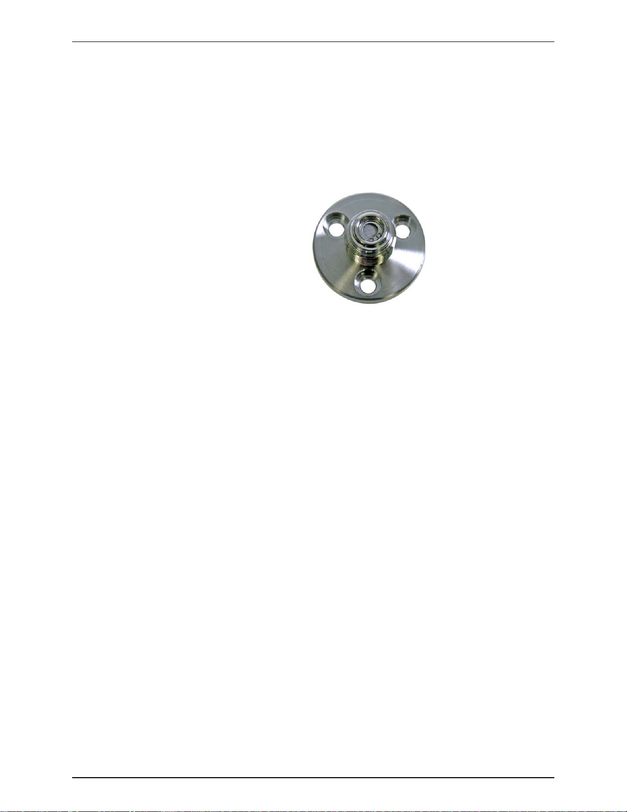
molbox™ RFM™ OPERATION AND MAINTENANCE MANUAL
In addition to the new data structure and modelization methods that became
available for molblocs with the introduction of molbox1+, all molbloc-L elements
of range 1E1-L to 3E4-L produced or upgraded af ter the r elease of m olbox1+ are
equipped standard with an upstream ¼” VCR flange, or f lowpath connection, that
has an integrated sintered metal filter. T his filter is intended to be a last defense
against particulate contamination of the molbloc-L internal flowpath which can
affect molbloc-L m easurem ents. Every eff ort should still be m ade to supply clean
dry gas to the molbloc to ensure its measurement performance and long-term
stability. molblocs that have the integrated upstream filter are recognizable by the
visible filter element as shown below.
Figure 1. molbloc-L Upstream End Flange with Integrated Filter
New molbloc-L elements produced with molbox1+ calibration data structure,
premium calibration options, and integrated filter hardware can be identified by
having a serial number of 6000 or higher. Most older molbloc-L elements are
eligible for upgrade to this hardware/version by Fluke Calibration.
1.1.1.2 molbloc-S Flow Eleme nt
molbloc-S elements us e critical (s onic) f low venturi nozzle technology to measure
flows, which overlap with the higher molbloc-L ranges and ex tend the high end of
the molbloc/molbox RFM system flow range. The mass flow rate through a
molbloc-S element is roughly proportional to the upstream absolute pressure
when the flow is “choked”, so the molbloc-S operating pres sure can vary widely
as the mass flow rate is changed throughout the flow range. The limits of
molbloc-S operating pressure and flow ranges are defined by the molbloc-S
calibration type, described in Section 1.2.4.2.2.
New calibration data structure and premium calibration options for molbloc-S
were also introduced along with molbox1+. molbloc-S elements produced with
this support will have serial num ber of 4000 or higher. O lder molbloc-S elem ents
are eligible for upgrade to this version format by Fluke Calibration.
1.2 Specifications
1.2.1 General Specifications
Power Requirements
Fuse
Operating Temperature Range
Storage Temperature Range
Vibration
Weight
Dimensions
© 2010 Fluke Calibration Page 2
85 to 264 VAC, 47 to 440 Hz, 18 VA m ax. c onsumption
1A/250V, slow blow, 5x20mm, NSN: 5920008930491
15 to 35 °C
-20 to 70 °C
Meets MIL-T-28800D
2.55 kg (5.6 lb) max.
8 cm H x 22.5 cm W x 20 cm D
(3.1 in. x 8.9 in. x 7.9 in.) approx.
Page 15

1. INTRODUCTION
Microprocessor
Communication Ports
Reference Pressure Transducers
(RPTs)
Ohmic Measurement System
Gases Supported
Pressure Connections
Pressure Limits
Flow Ranges
CE Conformance
Motorola 68302, 16 MHz
RS232 (COM1), RS232 (COM2), IEEE-488
Standard: 2 x 600 kPa (87 psia) calibrated range piezores i s tive silicon
Microrange option: 12.5 kPa (1.8 psi d) pi ezores i stive silicon
Resolution: 0.004 Ω
Accuracy: ± 0.04 Ω
Accuracy of 100 and 110 Ω ref erence resistors: ± 0.01 %
Stability of 100 and 110 Ω reference resistors: ± 0.005 % per three years
molbloc-L and molbloc -S
Nitrogen (N2), dry Air, humid Air (molbloc-S only) , Argon (Ar), B utane
(Butn), Carbon Monoxide (CO), Helium (He), Oxygen (O2), Carbon
Dioxide (CO2), Carbon Tetrafluoride (CF4), Octofluorocyclobutane
(C4F8), Ethane (C2H6), Ethylene (C2H4), Fluoroform (CHF3),
Hexafluoroethane (C2F6), Hydrogen (H2), Methane (CH4), Nitrous
Oxide (N2O), Propane (C3H8), Sulfur Hexafluoride (SF6), Xenon (Xe)
Quick connectors equivalent to Swagelok QM Series (-QM2-B200)
Maximum working pressure 600 kPa absolute (87 psi a)
Maximum pressure without damage 800 kPa absolute (115 psia)
NOTE: The microrange option includes a 12. 5 kPa (1.8 psi) differenti al
RPT which may be damaged by differenti al pressure greater than 100
kPa (15 psi).
See Sections 1.2.4. 1. 3, 1.2.4.1.4and 1.2.4.2. 1
Available. Must be specif i ed.
1.2.2 Reference Pressure Transducer (RPT) Specifications
1.2.2.1 Upstream and Downstream RPTs
Piezoresistive silicon
Type
Range
Resolution
Repeatability
Accuracy
1.2.2.2 Differential RPT (Microrange Option)
Range
Resolution
Repeatability
Accuracy
0 to 600 kPa absolute (0 to 87 psia)
6.0 Pa (0.0009 psi)
± 0.01 % FS
Absolute measurements: ± 0.06 % FS f or one year
Differential measurements: ± (20 Pa + 0.05 % ∆Ρ). T ari ng sequence eliminates zero
error on measurement of dif ference between the two RPTs.
Piezoresistive silicon
Type
0 to 12.5 kPa differenti al (0 t o 1.8 psid)
0.14 Pa (0.00002 psi)
± 0.01 % FS
± (0.14% of reading + 0.01% F.S .) for one year.
Taring sequence eliminates zero error.
Page 3 © 2010 Fluke Calibration
Page 16

molbox™ RFM™ OPERATION AND MAINTENANCE MANUAL
1.2.3 Temperature Measurement Specifications
Specifications are for m olbloc mounted Platinum Resistance T hermom eters (PRT ) combined
with molbox RFM resistance measurement system and temperature calculation.
Range
Accuracy
Resolution
0 to 40 °C
± 0.05 °C
0.01 °C
The molbox RFM internal res istance measurement system is autom atically calibrated using
reference 100 and 110 Ω (± 0.01 %) resistors (see Section 5.3).
1.2.4 Flow Measurement Specif i cations
molbox RFM meas ures the f low through molbloc flow elements. Ther e are two different types
of molblocs, molbloc-L (laminar) (see Section 1.1.1.1) and molbloc-S (sonic) (see Section
1.1.1.2). Flow measurement specifications, calibration types, ranges and dimensions are
detailed separately for each molbloc type in Section 1.2.4.1 and 1.2.4.2.
All flow measurem ent uncertainties are valid only for measurem ents in a gas for which the
molbloc is calibrated, and within the range of pressures for which the calibration is specified.
1.2.4.1 molbloc-L Flow Measurement Specifications, Model Ranges 1E1-L thru 3E4-L
The flow range, useable operating pressure and absolute and differential
pressure associated with molbloc -L operation depend on the molbloc used and its
pressure-dependent calibration options (s ee Section 1.2.4.1.2). Use of mobloc-L
model range 1E5-L is only recomm ended for us e with the mic rorange option (s ee
Section 1.2.4.1.1).
Measurement Update Rate
Range
Resolution
Linearity
Repeatability
Precision
Stability
(1 year)
Measurement Uncertainty
(1 year, N2 and any molbox RFM
supported gas for which the molbl oc
1 Precision: Combined linearity, hysteresis, repeatability.
2 Stability: Maximum change in zero and span over specified time period for typical molbox RFM and molbloc used
under typical conditions. As stability can only be predicted, stability for a specific molbox RFM should be
established from experience.
3 Measurement Uncertainty: Maximum deviation of the molbox RFM flow indication from the true value of the flow
through the molbloc including precision, stability and Fluke calibration standard uncertainty. Measurement
uncertainty specifications for molblocs are valid only for gases with which the molbloc has been calibrated. All
molblocs are calibrated for N
maintained at all times for all gases on all molbloc designations. Check for availability before ordering.
in use is calibrated)
2. Calibrations with other gases are optional. Fluke calibration capability is not
1 second
0 to molbloc full s cale depending on gas and molbloc
pressure dependent calibration type
(see Section 1.2.4.1.2).
0.01 % FS
± 0.23 % of reading from 10 t o 100 % F S,
± 0.023 % FS under 10 % FS
± 0.1 of reading from 10 to 100 % F S,
± 0.01 % FS under 10 % FS
1
± 0.25 % of reading from 10 t o 100 % FS,
± 0.025 % FS under 10 % FS
2
± 0.15 % of reading from 10 t o 100 % F S,
± 0.015 % FS under 10 % FS
3
± 0.5 % of reading from 10 t o 100 % F S,
± 0.05 % FS under 10 % FS
© 2010 Fluke Calibration Page 4
Page 17

1. INTRODUCTION
1.2.4.1.1 molbloc-L FLOW MEASUREMENT
SPECIFICATIONS, MICRORANGE OPTION
The microrange option (see Section 1.2.2.2) improves molbloc-L flow
measurement s pecifications below 10 % FS of the molbloc model ranges 1E1-L
thru 3E4-L, and is required to achieve the measurement specification of molbloc
model range 1E5-L. With the microrange option, the affected measurement
specifications become:
Molbloc-L (Ranges 1E1-L Thru 3E4-L)
Update Rate
Range
Resolution
Linearity
Repeatability
Precision
Stability
(1 year)
Measurement Uncertainty
molbloc-L (Ranges 1E5-L Only)
Update Rate
Range
Resolution
Linearity
Repeatability
Precision
Stability
(1 year)
Measurement Uncertainty
1 Precision: Combined linearity, hysteresis, repeatability.
2 Stability: Maximum change in zero and span over specified time period for typical molbox RFM and molbloc used
under typical conditions. As stability can only be predicted, stability for a specific molbox RFM should be
established from experience.
3 Measurement Uncertainty: Maximum deviation of the molbox RFM flow indication from the true value of the
flow through the molbloc including precision, stability and Fluke calibration standard uncertainty. Measurement
uncertainty specifications for molblocs are valid only for gases with which the molbloc has been calibrated. All
molblocs are calibrated for N
maintained at all times for all gases on all molbloc designations. Check for availability before ordering.
2. Calibrations with other gases are optional. Fluke calibration capability is not
1 second
0 to molbloc full s cale depending on gas and molbloc
pressure dependent calibration type (s ee molbloc-L tables)
0.01% FS, 0.001% FS under 10% FS
±0.23% of reading from 1 to 100% FS,
±0.0023% FS under 1% FS
±0.1% of reading from 1 to 100% FS,
±0.001% FS under 1% FS
1
±0.25% of reading from 1 to 100% FS,
±0.0025% FS under 1% FS
2
±0.15% of reading from 1 to 100% FS,
±0.0015% FS under 1% FS
3
±0.5% of reading from 1 to 100% FS,
±0.005% FS under 1% FS
1 second
0 to molbloc full scale depending on gas and molbloc
pressure dependent calibration type (s ee molbloc-L tables)
0.01% FS
± 0.25% of reading from 5 to 100% FS,
± 0.0125% FS under 5% FS
± 0.2% of reading from 5 t o 100% F S,
± 0.01% FS under 5% FS
1
± 0.32% of reading from 5 to 100% FS,
± 0.016% FS under 5% FS
2
± 0.2% of reading from 5 to 100% FS,
± 0.01% FS under 5% FS
3
± 0.5% of reading from 5 to 100% FS,
± 0.025% FS under 5% FS
Page 5 © 2010 Fluke Calibration
Page 18
molbox™ RFM™ OPERATION AND MAINTENANCE MANUAL
PRESSURE AT MAX. FLOW
MOLBLOC
MOLBLOCS
1.2.4.1.2 molbloc-L Pressure Dependent Calibration Types
See your molbloc’s Calibration Report to determine the
calibration type of the molbloc you are using.
Different pressure dependent calibration options for molbloc-L elements determine
the range of operating pressures over which a molbloc can be used within its
mass flow measurement specifications. The calibration option also affects the
molbloc flow range and the differential pressure associated with the flow range.
Measurement uncertainty (accuracy) specifications for molbloc-L are valid only for
gases with which the molbloc has been calibrated. All m olbloc-L elements are
calibrated for N2. Calibrations with other gases are optional. Fluke calibration
capability is not maintained at all times for all gases on all molbloc designations.
Check for availability before ordering calibrations.
The molbloc-L pressure dependent calibration types are summarized in Table 1.
Table 1. molbloc-L Pressure Dependent Calibration Types
Note
CALIBRATION TYPE
(CALIBRATION NAME)
Low pressure
(LOP)
High pressure
(HIP)
Downstream
(DOWN)
OPERATING PRESSURE
200 to 325 kPa absolute
(29 to 48 psia)
upstream of molbloc
325 to 525 kPa absolute
(48 to 76 psia)
upstream of molbloc
Atmospheric pressure
downstream of m ol bl oc. 85 to
105 kPa (12 to15 psia).
NOMINAL DIFFERENTIAL
1E5
5 kPa
(.725 psi)
Not available 50 kPa
12.5 kPa
(1.8 psi)
ALL OTHER
50 kPa
(7.5 psi)
(7.5 psi)
80 kPa (12 psi)
Note
Differential pressure values are nominal and may vary by up to
15 % with the actual molbloc used.
© 2010 Fluke Calibration Page 6
Page 19

1. INTRODUCTION
2
CARBONS
1.2.4.1.3 molbloc-L Ranges with Low Pressure Calibrations
Table 2. molbloc-L Ranges with Low Pressure and Downstream Calibrations
SIZE
Nitrogen
GASES
N
SIZE
1E1
5E1
10 50 100 200 500 1,000 5,000 10,000 30,000 100,000
Argon Ar 10 50 100 200 500 1,000 5,000 10,000 30,000 80,000
Helium He 10 50 100 200 500 1,000 5,000 10,000 30,000 100,000
Sulfur Hexafluoride
INERT
SF
10 50 100 200 500 1,000 2,000
6
Xenon XE 10 40 80 150 400 800 3,500
Butane
Ethane
Ethylene
Hydrogen
FLAMMABLE
Methane
Propane
Carbon
Tetrafluoride
Hexafluorethene
Trifluoromethane
FLUORO-
C
4H1
0
C
2H6
C
2H4
H
2
CH
C
3H8
CF
C
2F6
CHF
20 100 130
20 100 200 400 1,000 2,000 6,000
16 80 160 320 800 1 600 7,000
20 100 200 400 1,000 2,000 10,000 20,000 60,000 200,000
16 80 160 320 800 1 600 8,000 16,000 40,000
4
20 100 200 400 1,000 2,000 3,000
10 50 100 200 500 1,000 4,000
4
10 50 100 200 500 1,000 2,000
10 50 100 200 500 1,000 4,000
3
Air Air 10 50 100 200 500 1,000 5,000 10,000 30,000 100,000
Carbon Dioxide
CO
10 50 100 200 500 1,000 5,000 10,000 20,000
2
Carbon Monoxide CO 10 50 100 200 500 1,000 5,000 10,000 30,000 100,000
Nitrous Oxide
N
2
10 50 100 200 500 1,000 5,000 10,000 20,000
O
OTHER
C
Octafluorocyclobutane1
Oxygen
15 60 9 65
4F8
O
2
10 50 100 200 500 1,000 5,000 10,000 30,000 80,000
See Table 3 for footnotes.
molbloc-L SIZE AND FULL SCALE FLOW (sccm @ 0 ºC)
SIZE
1E2
SIZE
2E2
SIZE
5E2
SIZE
1E3
SIZE
5E3
500
500
270
30
50
670
140
2,300 2,200
1,400
18,000
1,000
16,000 20,000
1,000
10,000
1,000
10,000 12,000
600
600
10,000 12,000
600
130
17
34
330
85
1,100
175
1,050
840
SIZE
1E4
6,000
1,000
SIZE
3E4
6,000
4,000
8,000 11,000
3,000
7,000
3,000
---
---
18,000
2,000
6,000
5,000
5,000
10,000
2,000
7,000
3,000
6,000
1,200
6,000
4,000
4,000
4,000
4,000
3,400
--- ---
1,700
SIZE
1E5
---
---
30,000
20,000
---
---
60,000
50,000
70,000
40,000
120,000
40,000
---
---
36,000
25,000
---
---
38,000
30,000
60,000
30,000
60,000
30,000
Page 7 © 2010 Fluke Calibration
Page 20

molbox™ RFM™ OPERATION AND MAINTENANCE MANUAL
CARBONS
1.2.4.1.4 molbloc-L Ranges with High Pressure Calibrations
Table 3. molbloc-L Ranges with High Pressure Calibrations
GASES
Nitrogen
SIZE
SIZE
1E1
5E1
N
2
20 100 200 400 1,000 2,000 10,000 20,000 40,000
molbloc-L SIZE AND FULL SCALE FLOW (sccm @ 0 ºC)
SIZE
SIZE
1E2
2E2
SIZE
5E2
SIZE
1E3
SIZE
5E3
SIZE
1E4
SIZE
3E4
7,500
Argon Ar 20 100 200 400 1,000 2,000 10,000 17,000 35,000
6,000
Helium He 20 100 200 400 1,000 2,000 10,000 20,000 65,000 N/A
INERT
Sulfur Hexafluoride
SF
6
Xenon XE 20 100 150 350 650 1,700 3,350
Butane
Ethane
Ethylene
Hydrogen
Methane
FLAMMABLE
Propane
Carbon
Tetrafluoride
Hexafluorethene
FLUORO-
Trifluoromethane
C
4H10
C
2H6
C
2H4
H
2
CH
C
3H8
CF
C
2F6
CHF
4
25 100
15
120
30
250
50
600
150
2,000
300
2,000
1,400
6,200
2,800
11,000
950
1,900
N/A N/A N/A N/A N/A N/A N/A N/A N/A N/A
40 200 350
40 200 350 700 2,000 4,000 7,000
50
700
100
1,800
200
4,000 6,000
2 300
2,000
20,000
4,500
22,000
4,000
40 200 400 900 2,000 4,500 22,000 45,000 130,000 N/A
35 175 350 700 1,700 3,500 13,000
4
50 200
20 100 200 400 1,000 2,000 3,700
25 100
25 125 240
3
25
15
200
50
120
30
30
400
100
250
50
450
60
1,000
250
600
150
1,200
150
2,000
3,500
500
3,500
2,600
1,200
2,000
300
1,800
1,500
2,500 4,000
1,500
33,000 42,000
11,000
5,400
12,000
2,400
6,000
3,000
12,000
3,000
--
--
11,000
5,700
20,000
13,000
22,000
12,700
12,000
--
--
12,000
7,300
--
--
12,000
8,800
Air Air 20 100 200 400 1,000 2,000 10,000 20,000 40,000
7,200
Carbon Dioxide
CO
25 125 250 500 1,250 2,500 6,600
2
1,400
20,000
2,500
20,000
8,800
Carbon Monoxide CO 20 100 200 400 1,000 2,000 10,000 20,000 40,000
7,500
Nitrous Oxide
OTHER
Octafluorocyclobutane2
Oxygen
N
O
2
C
4F8
O
2
25 125 250 500 1,250 2,500 11,000
1,500
20,000
3,000
20,000
9,000
N/A N/A N/A N/A N/A N/A N/A N/A N/A N/A
20 100 200 400 1,000 2,000 10,000 20,000 40,000
6,500
SIZE
1E5
N/A
N/A
N/A
N/A
N/A
N/A
N/A
N/A
N/A
N/A
N/A
N/A
N/A
N/A
N/A
N/A
A bold value indicates that the maximum flow is li mited by the maximum Reynolds number value of 1 200 which is reached
before the normal differenti al pressure range is reached. In that c ase, the second value gives the minimum flow for which
measurement uncert ai nt y (ac curacy) is equal to the nominal uncertainty specific at i on. Divide the second value by 10 when
using molbox RFM microrange option.
Where there is no value in t he field (–), this indicates that the maximum Reynolds number is reached before the di fferential
pressure reaches 5 kPa (1 kPa i n the case of the 1E5 molbl oc), therefore calibration with that gas is not useful.
1
Due to low vapor pressure, only downstream calibrati on type is available.
2
The operating pressure range is greater than t he vapor pressure value for this gas.
© 2010 Fluke Calibration Page 8
Page 21

1. INTRODUCTION
1.2.4.1.5 molbloc-L DIMENSIONS
5E3 AND LOWER 1E4, 3E4 1E5
58.50 (2.303) 74.50 (2.933) 74.50 (2.933)
A
16.00 (0.630) 24.00 (0.945) 24.00 (0.945)
B
32.00 (1.260) SQ 48.00 (1.890) SQ 48.00 (1.890) SQ
C
68.84 (2.750) 80.00 (3.150) 80.00 (3.150)
D
19.06 (0.750) 28.00 (1.102) 28.00 (1.102)
E
124.00 (4.881) 157.00 (6.181) 164.00 (6.458)
F
1/4 in. VCR M 1/4 in. VCR M 1/2 in. VCR M
G
molbloc-L SIZES [mm(in.)]
Page 9 © 2010 Fluke Calibration
Page 22

molbox™ RFM™ OPERATION AND MAINTENANCE MANUAL
calibration
1.2.4.2 molbloc-S
The flow range and operating pressure associated with molbloc-S operation
depend on the molbloc used and its calibration options (see Section 1.2.4.2.2)
Measurement Update
Range
Resolution
Linearity
Repeatability
Precision
Predicted Stability
(1 year)
Measurement
Uncertainty
With SP molbloc-S
calibration
Measurement
Uncertainty
With LP molbloc-S
calibration
Measurement
Uncertainty
With HP molbloc-S
1 Precision: Combined linearity, hysteresis, repeatability.
2. Stability: Maximum change in zero and span over specified time period for typical molbox RFM and molbloc
used under typical conditions. As stability can only be predicted, stability for a specific molbloc and molbox
RFM should be established from experience.
3. Measurement uncertainty (accuracy): Maximum deviation of the molbox RFM flow indication from the true value
of the flow through the molbloc including precision, stability and Fluke calibration standard measurement
uncertainty.
1 second
Rate
Depends on molbloc-S pressure dependent calibration type
(see Section 1.2.4.2. 2)
0.01 % of FS
± 0.25 % of reading
± 0.10 % of reading
1
± 0.30 % of reading
2
± 0.2 % of reading
± 0.5 % of reading from 50 to 500 kPa
3
± 0.5 % of reading from 50 t o 200 kPa
3
± 0.5 % of 50 kPa flow from 20 to 50 kPa
± 0.5 % of reading from 200 to 600 kPa
3
1.2.4.2.1 molbloc-S Pressure Dependent Calibration Types
See your molbloc’s Calibration Report to determine the
calibration type of the molbloc you are using.
Measurement uncertainty (accuracy) specificat ions for molbloc s are valid only for
gases with which the m olbloc has been calibrated. All molbloc-S elements are
calibrated in one standard gas, either air or N2, and m ay be calibrated in other
gases. Calibrations with other gases are optional. The list of gases which can be
measured by molbloc-S is the sam e as molbloc-L. FLUKE calibration capability
is not maintained at all times for all gases on all molbloc designations. Check for
availability before ordering calibrations.
molbloc-S calibrations are performed over flow ranges corres ponding to one of
three pressure ranges, summarized in Table 4.
© 2010 Fluke Calibration Page 10
Note
Page 23

Table 4: molbloc-S Calibration Types
1. INTRODUCTION
CALIBRATION TYPE
(CALIBRATION NAME)
Low pressure
(LP)
Standard pressure
(SP)
High pressure
(HP)
OPERATING PRESSURE
20 to 200 kPa absolute
(3 to 30 psia)
upstream of molbloc
50 to 500 kPa absolute
(7 to 70 psia)
upstream of molbloc
200 to 2000 kPa absolute
(29 to 290 psia)
upstream of molbloc
Note
molbloc-S flow measurements are valid only when the ratio of
pressure downstream to the pressur e ups tre am of th e nozzle is low
enough to assure a critical (choked) flow (see Section 3.1.5).
1.2.4.2.2 molbloc-S Ranges
molbloc-S flow ranges are defined by the molbloc’s Pres sure to Flow Conversion
Ratio, K
molbloc-S, the downstream pr ess ur e and the acceptable back pressure ratio (see
Section 3.1.5). K
between mass f low in nitrogen and the absolute upstream press ure delivered to
the molbloc-S. molbloc-S s izes are defined by the nominal K
nozzle, using scientific notation, for example a 1E3 molbloc -S has a K
sccm/k Pa. To differentiate from molbloc-L size designations, this molbloc s ize is
designated 1E3-S.
, the gas used, the absolute pressure that can be delivered upstream of
F
is expressed in units of s ccm/k Pa and defines the relationship
F
of the molbloc-S
F
of 1,000
F
The molbox RFM pressure range, the molbloc-S calibration type (see Section
1.2.5.2.2) and the back pressure ratio (BPR) requirements limit the pressures, and
flows, over which a molbloc-S can be used within known measurement
uncertainty limits. In practice, the usable range of a molbloc-S in a given
application also may depend on the available gas supply pressure, the presence and
flow capacity of a vacuum pump downstream or the allowable back pres sure on an
upstream DUT.
The mass f low range of a m olbloc-S element is dependent on the properties of the gas
used, so the range of a molbloc-S is diff erent f or each support ed gas. The f low ranges
for each molbloc-S size at various typical operating pressures are summarized
separately for each molbloc-S supported gas in the Tables below. For the common
application of using a molbloc-S with its downstream pressure at or near atmospher ic
pressure, it is helpful to know what minimum flow can be measured before violating back
pressure ratio requirements (see Section 3.1.5). In the tables below, this minimum flow
value is given in the “Minimum without vacuum” column.
FLUKE calibration capability may not be available for som e of the gas es listed, or
may be limited to less than the maxim um flow rate listed. Check for availability
before ordering calibrations.
The following notes apply to the ra nge table s below:
Ratio = Inverse square root density ratio of the current gas to Nitrogen
KF = Pressure to Flow Conversion Ratio, sccm/kPa
To estimate a f low in a given gas at a given pres s ure: F low(slm) = KF * Pressure
in kPa absolute / 1000 * Gas Ratio
Page 11 © 2010 Fluke Cali brat i on
Page 24

molbox™ RFM™ OPERATION AND MAINTENANCE MANUAL
Ratio = 1
DESIGNATOR
[sccm/ kPa]
(3 psia)
(7 psia)
(15 psia)
vacuum
(30 psia)
(70 psia)
(100 psia)
(174 psia)
(290 psia)
DESIGNATOR
[sccm/ kPa]
(3 psia)
(7 psia)
(15 psia)
vacuum
(30 psia)
(70 psia)
(100 psia)
(174 psia)
(290 psia)
Table 5: N2. molbloc-S Flow in Nitrogen at Various molbloc Upstream Pressures
Nitrogen
N2
KF
molbloc-S MASS FLOW RATE (slm @ 0 °C) WHEN molbloc-S UPSTREAM PRESSURE IS:[1][2]
20 kPa
50 kPa
100 kPa
Minimum
witout
(3)
200 kPa
500 kPa
700 kPa
1.2 MPa
2 MPa
1E1-S
2E1-S
5E1-S
1E2-S
2E2-S
5E2-S
1E3-S
2E3-S
5E3-S
1E4-S
Argon
Ratio = 0.837 Ar
100 2 5 10 15 20 50
200 4 10 20 28 40 100
500 10 25 50 67 100 250
1,000 20 50 100 129 200 500
2,000 40 100 200 248 400 1,000
5,000 100 250 500 596 1,000 2500
10,000 200 500 1,000 1,173 2,000 5,000
KF
10 0.2 0.5 1 2.0 2 5
20 0.4 1 2 3.5 4 10
50 1 2.5 5 7.7 10 25
[1] Flow values in table are valid only when critical flow is established.
[2] When volumetrically based mass flow units with reference temperatures other than 0°C are used, flow values will
generally be higher; the flow values for a given molbloc and upstream pressure are approximately 7% higher
when expressed in slm at 20°C. Flow values at a given pressure may vary by up to ± 2% due to flowpath
machining tolerances.
[3] Minimum upstream pressure to achieve critical flow with atmospheric pressure (approximately 100 kPa)
downstream of molbloc-S (no vacuum).
7
14
35
70
140
350
700
1,400
3,500
7,000
12 20
24 40
60 100
120 200
240 400
600 1,000
1,200 2,000
2,400 4,000
6,000 10,000
12,000 20,000
Table 6: Ar. molbloc-S Flow in Argon at Various molbloc Upstream Pressures
molbloc-S MASS FLOW RATE (slm @ 0 °C) WHEN molbloc-S UPSTREAM PRESSURE IS:[1][2]
20 kPa
50 kPa
100 kPa
Minimum
witout
(3)
200 kPa
500 kPa
700 kPa
1.2 MPa
2 MPa
1E1-S
2E1-S
5E1-S
1E2-S
2E2-S
5E2-S
1E3-S
2E3-S
5E3-S
10 0.2 0.4 0.8 1.7 1.7 4.2 5.9 10.0 16.7
20 0.3 0.8 1.7 3.0 3.3 8.4 11.7 20.1 33.5
50 0.8 2.1 4.2 6.5 8.4 20.9 29.3 50.2 83.7
100 1.7 4.2 8.4 12.9 16.7 41.9 58.6 100.5 167.4
200 3.3 8.4 16.7 23.3 33.5 83.7 117.2 200.9 334.9
500 8.4 20.9 41.9 57.1 83.7 209.3 293.0 502.3 837.2
1,000 16.7 41.9 83.7 107.8 167.4 418.6 586.0 1,004.6 1,674.4
2,000 33.5 83.7 167.4 207.6 334.9 837.2 1,172.1 2,009.3 3,348.8
5,000 83.7 209.3 418.6 498.2 837.2 2,093.0 2,930.2 5,023.2 8,372.0
10,046.4 16,744.
1E4-S
10,000 167.4 418.6 837.2 996.2 1,674.4 4,186.0 5,860.4
[1] Flow values in table are valid only when critical flow is established.
[2] When volumetrically based mass flow units with reference temperatures other than 0°C are used, flow values will
generally be higher; the flow values for a given molbloc and upstream pressure are approximately 7% higher
when expressed in slm at 20°C. Flow values at a given pressure may vary by up to ± 2% due to flowpath
machining tolerances.
[3] Minimum upstream pressure to achieve critical flow with atmospheric pressure (approximately 100 kPa)
downstream of molbloc-S (no vacuum).
0
© 2010 Fluke Calibration Page 12
Page 25

1. INTRODUCTION
DESIGNATOR
[sccm/ kPa]
(3 psia)
(7 psia)
(15 psia)
vacuum
(30 psia)
(70 psia)
(100 psia)
(174 psia)
(290 psia)
DESIGNATOR
[sccm/ kPa]
(3 psia)
(7 psia)
(15 psia)
vacuum
(30 psia)
(70 psia)
(100 psia)
(174 psia)
(290 psia)
Table 7: He. molbloc-S Flow in Helium at Various molbloc Upstream Pressures
Helium
Ratio = 2.647 He
KF
1E1-S
2E1-S
5E1-S
1E2-S
2E2-S
5E2-S
1E3-S
2E3-S
5E3-S
1E4-S
10 0.5 1.3 2.6 9.4 5.3 13.2 18.5 31.8
20 1.1 2.6 5.3 13.1 10.6 26.5 37.1 63.5 105.9
50 2.6 6.6 13.2 25.7 26.5 66.2 92.6 158.8
100 5.3 13.2 26.5 51.4 52.9 132.3 185.3 317.6 529.4
200 10.6 26.5 52.9 91.5 105.9 264.7 370.6 635.2
500 26.5 66.2 132.3 199.4 264.7 661.7 926.4 1,588.1 2,646.8
1000 52.9 132.3 264.7 398.7 529.4 1,323.4 1,852.8 3,176.2
2000 105.9 264.7 529.4 695.1 1,058.7 2,646.8 3,705.5 6,352.3 10,587.2
5000 264.7 661.7 1,323.4 1,737.8 2,646.8 6,617.0 9,263.8 15,880.9
10,000 529.4 1,323.4 2,646.8 3,281.0 5,293.6 13,234.0 18,527.7 31,761.7 52,936.2
molbloc-S MASS FLOW RATE (slm @ 0 °C) WHEN molbloc-S UPSTREAM PRESSURE IS:[1][2]
20 kPa
50 kPa
100 kPa
Minimum
witout
(3)
200 kPa
500 kPa
700 kPa
1.2 MPa
2 MPa
52.9
264.7
1,058.7
5,293.6
26,468.1
[1] Flow values in table are valid only when critical flow is established.
[2] When volumetrically based mass flow units with reference temperatures other than 0°C are used, flow values will
generally be higher; the flow values for a given molbloc and upstream pressure are approximately 7% higher
when expressed in slm at 20°C. Flow values at a given pressure may vary by up to ± 2% due to flowpath
machining tolerances.
[3] Minimum upstream pressure to achieve critical flow with atmospheric pressure (approximately 100 kPa)
downstream of molbloc-S (no vacuum).
Table 8: SF6. molbloc-S Flow in Sulfur Hexafluoride at Various molbloc Upstream Pressures
Sulfur Hexafluoride
Ratio = 0.435 SF6
KF
1E1-S
2E1-S
5E1-S
1E2-S
2E2-S
5E2-S
1E3-S
2E3-S
5E3-S
1E4-S
10 0.1 0.2 0.4 0.8 0.9 2.2 3.0 n/a
20 0.2 0.4 0.9 1.4 1.7 4.3 6.1 n/a
50 0.4 1.1 2.2 3.1 4.3 10.9 15.2 n/a
100 0.9 2.2 4.3 5.9 8.7 21.7 30.4 n/a
200 1.7 4.3 8.7 11.4 17.4 43.5 60.9 n/a
500 4.3 10.9 21.7 26.9 43.5 108.7 152.2 n/a
1,000 8.7 21.7 43.5 53.8 87.0 217.4 304.3 n/a
2,000 17.4 43.5 87.0 100.0 173.9 434.8 608.7 n/a
5,000 43.5 108.7 217.4 249.9 434.8 1,086.9 1,521.7 n/a
10,000 87.0 217.4 434.8 499.7 869.5 2,173.8 3,043.4 n/a
molbloc-S MASS FLOW RATE (slm @ 0 °C) WHEN molbloc-S UPSTREAM PRESSURE IS:[1][2]
20 kPa
[1] Flow values in table are valid only when critical flow is established.
[2] When volumetrically based mass flow units with reference temperatures other than 0°C are used, flow values will
[3] Minimum upstream pressure to achieve critical flow with atmospheric pressure (approximately 100 kPa)
[4] Operation in this gas is limited to lower pressures due to the gas vapor pressure.
50 kPa
generally be higher; the flow values for a given molbloc and upstream pressure are approximately 7% higher
when expressed in slm at 20°C. Flow values at a given pressure may vary by up to ± 2% due to flowpath
machining tolerances.
downstream of molbloc-S (no vacuum).
100 kPa
Minimum
witout
200 kPa
(3)
500 kPa
700 kPa
1.2 MPa
[4]
n/a
[4]
n/a
[4]
n/a
[4]
n/a
[4]
n/a
[4]
n/a
[4]
n/a
[4]
n/a
[4]
n/a
[4]
n/a
2 MPa
[4]
[4]
[4]
[4]
[4]
[4]
[4]
[4]
[4]
[4]
Page 13 © 2010 Fluke Cali brat i on
Page 26

molbox™ RFM™ OPERATION AND MAINTENANCE MANUAL
DESIGNATOR
[sccm/ kPa]
(3 psia)
(7 psia)
(15 psia)
vacuum
(30 psia)
(70 psia)
(100 psia)
(174 psia)
(290 psia)
DESIGNATOR
[sccm/ kPa]
(3 psia)
(7 psia)
(15 psia)
vacuum
(30 psia)
(70 psia)
(100 psia)
(174 psia)
(290 psia)
Table 9: Xe. molbloc-S Flow in Xenon at Various molbloc Upstream Pressures
Xenon
Ratio = 0.460 Xe
KF
1E1-S
2E1-S
5E1-S
1E2-S
2E2-S
5E2-S
1E3-S
2E3-S
5E3-S
1E4-S
10 0.1 0.2 0.4 0.8 0.7 1.8 3.2 n/a
20 0.1 0.4 0.7 1.4 1.5 3.6 6.4 n/a
50 0.4 0.9 1.8 3.6 3.6 9.1 16.1 n/a
100 0.7 1.8 3.6 6.5 7.3 18.2 32.2 n/a
200 1.5 3.6 7.3 12.9 14.6 36.4 64.5 n/a
500 3.6 9.1 18.2 29.7 36.4 91.0 161.2 n/a
1,000 7.3 18.2 36.4 59.3 72.8 182.0 322.3 n/a
2,000 14.6 36.4 72.8 109.6 145.6 364.0 644.6 n/a
5,000 36.4 91.0 182.0 267.2 364.0 910.0 1,611.5 n/a
10,000 72.8 182.0 364.0 529.2 728.0 1,819.9 3,223.1 n/a
molbloc-S MASS FLOW RATE (slm @ 0 °C) WHEN molbloc-S UPSTREAM PRESSURE IS:[1][2]
20 kPa
[1] Flow values in table are valid only when critical flow is established.
[2] When volumetrically based mass flow units with reference temperatures other than 0°C are used, flow values will
[3] Minimum upstream pressure to achieve critical flow with atmospheric pressure (approximately 100 kPa)
[4] Operation in this gas is limited to lower pressures due to the gas vapor pressure.
50 kPa
generally be higher; the flow values for a given molbloc and upstream pressure are approximately 7% higher
when expressed in slm at 20°C. Flow values at a given pressure may vary by up to ± 2% due to flowpath
machining tolerances.
downstream of molbloc-S (no vacuum).
100 kPa
Minimum
witout
200 kPa
(3)
500 kPa
700 kPa
1.2 MPa
[4]
n/a
[4]
n/a
[4]
n/a
[4]
n/a
[4]
n/a
[4]
n/a
[4]
n/a
[4]
n/a
[4]
n/a
[4]
n/a
2 MPa
[4]
[4]
[4]
[4]
[4]
[4]
[4]
[4]
[4]
[4]
Butane
Ratio = 0.680 C4H10
KF
1E1-S
2E1-S
5E1-S
1E2-S
2E2-S
5E2-S
1E3-S
2E3-S
5E3-S
1E4-S
10 0.1 0.3 0.7 1.0 1.4 n/a
20 0.3 0.7 1.4 1.9 2.7 n/a
50 0.7 1.7 3.4 4.8 6.8 n/a
100 1.4 3.4 6.8 9.0 13.6 n/a
200 2.7 6.8 13.6 18.0 27.2 n/a
500 6.8 17.0 34.0 42.2 68.0 n/a
1,000 13.6 34.0 68.0 84.4 136.0 n/a
2,000 27.2 68.0 136.0 157.0 272.0 n/a
5,000 68.0 170.0 340.0 392.4 679.9 n/a
10,000 136.0 340.0 679.9 784.9 1,359.8 n/a
Table 10: C4H10. molbloc-S Flow in Butane at Various molbloc Upstream Pressures
molbloc-S MASS FLOW RATE (slm @ 0 °C) WHEN molbloc-S UPSTREAM PRESSURE IS:[1][2]
20 kPa
[1] Flow values in table are valid only when critical flow is established.
[2] When volumetrically based mass flow units with reference temperatures other than 0°C are used, flow values will
[3] Minimum upstream pressure to achieve critical flow with atmospheric pressure (approximately 100 kPa)
[4] Operation in this gas is limited to lower pressures due to the gas vapor pressure.
50 kPa
generally be higher; the flow values for a given molbloc and upstream pressure are approximately 7% higher
when expressed in slm at 20°C. Flow values at a given pressure may vary by up to ± 2% due to flowpath
machining tolerances.
downstream of molbloc-S (no vacuum).
100 kPa
Minimum
witout
200 kPa
(3)
500 kPa
[4]
n/a
[4]
n/a
[4]
n/a
[4]
n/a
[4]
n/a
[4]
n/a
[4]
n/a
[4]
n/a
[4]
n/a
[4]
n/a
700 kPa
[4]
n/a
[4]
n/a
[4]
n/a
[4]
n/a
[4]
n/a
[4]
n/a
[4]
n/a
[4]
n/a
[4]
n/a
[4]
n/a
1.2 MPa
[4]
n/a
[4]
n/a
[4]
n/a
[4]
n/a
[4]
n/a
[4]
n/a
[4]
n/a
[4]
n/a
[4]
n/a
[4]
n/a
2 MPa
[4]
[4]
[4]
[4]
[4]
[4]
[4]
[4]
[4]
[4]
© 2010 Fluke Calibration Page 14
Page 27

1. INTRODUCTION
DESIGNATOR
[sccm/ kPa]
(3 psia)
(7 psia)
(15 psia)
vacuum
(30 psia)
(70 psia)
(100 psia)
(174 psia)
(290 psia)
DESIGNATOR
[sccm/ kPa]
(3 psia)
(7 psia)
(15 psia)
vacuum
(30 psia)
(70 psia)
(100 psia)
(174 psia)
(290 psia)
Table 11: C2H6. molbloc-S Flow in Ethane at Various molbloc Upstream Pressures
Ethane
Ratio = 0.960 C2H6
KF
1E1-S
2E1-S
5E1-S
1E2-S
2E2-S
5E2-S
1E3-S
2E3-S
5E3-S
1E4-S
10 0.2 0.5 1.0 1.5 1.9 4.8 6.7 n/a
20 0.4 1.0 1.9 3.0 3.8 9.6 13.4 n/a
50 1.0 2.4 4.8 6.7 9.6 24.0 33.6 n/a
100 1.9 4.8 9.6 13.4 19.2 48.0 67.2 n/a
200 3.8 9.6 19.2 25.2 38.4 96.0 134.5 n/a
500 9.6 24.0 48.0 61.9 96.0 240.1 336.1 n/a
1,000 19.2 48.0 96.0 118.7 192.1 480.2 672.3 n/a
2,000 38.4 96.0 192.1 228.6 384.2 960.4 1,344.6 n/a
5,000 96.0 240.1 480.2 551.9 960.4 2,401.0 3,361.4 n/a
10,000 192.1 480.2 960.4 1,103.8 1,920.8 4,802.0 6,722.8 n/a
molbloc-S MASS FLOW RATE (slm @ 0 °C) WHEN molbloc-S UPSTREAM PRESSURE IS:[1][2]
20 kPa
[1] Flow values in table are valid only when critical flow is established.
[2] When volumetrically based mass flow units with reference temperatures other than 0°C are used, flow values will
[3] Minimum upstream pressure to achieve critical flow with atmospheric pressure (approximately 100 kPa)
[4] Operation in this gas is limited to lower pressures due to the gas vapor pressure.
50 kPa
generally be higher; the flow values for a given molbloc and upstream pressure are approximately 7% higher
when expressed in slm at 20°C. Flow values at a given pressure may vary by up to ± 2% due to flowpath
machining tolerances.
downstream of molbloc-S (no vacuum).
100 kPa
Minimum
witout
200 kPa
(3)
500 kPa
700 kPa
1.2 MPa
[4]
n/a
[4]
n/a
[4]
n/a
[4]
n/a
[4]
n/a
[4]
n/a
[4]
n/a
[4]
n/a
[4]
n/a
[4]
n/a
2 MPa
[4]
[4]
[4]
[4]
[4]
[4]
[4]
[4]
[4]
[4]
Ethylene
Ratio = 0.996 C2H4
KF
1E1-S
2E1-S
5E1-S
1E2-S
2E2-S
5E2-S
1E3-S
2E3-S
5E3-S
1E4-S
10 0.2 0.5 1.0 1.7 2.0 5.0 7.0 n/a
20 0.4 1.0 2.0 3.1 4.0 10.0 13.9 n/a
50 1.0 2.5 5.0 7.5 10.0 24.9 34.9 n/a
100 2.0 5.0 10.0 13.9 19.9 49.8 69.7 n/a
200 4.0 10.0 19.9 27.7 39.8 99.6 139.4 n/a
500 10.0 24.9 49.8 64.2 99.6 248.9 348.5 n/a
1,000 19.9 49.8 99.6 128.2 199.2 497.9 697.0 n/a
2,000 39.8 99.6 199.2 237.0 398.3 995.8 1394.1 n/a
5,000 99.6 248.9 497.9 572.2 995.8 2,489.5 3485.2 n/a
10,000 199.2 497.9 995.8 1,144.4 1,991.6 4,978.9 6970.5 n/a
Table 12: C2H4. molbloc-S Flow in Ethylene at Various molbloc Upstream Pressures
molbloc-S MASS FLOW RATE (slm @ 0 °C) WHEN molbloc-S UPSTREAM PRESSURE IS:[1][2]
20 kPa
[1] Flow values in table are valid only when critical flow is established.
[2] When volumetrically based mass flow units with reference temperatures other than 0°C are used, flow values will
[3] Minimum upstream pressure to achieve critical flow with atmospheric pressure (approximately 100 kPa)
[4] Operation in this gas is limited to lower pressures due to the gas vapor pressure.
50 kPa
generally be higher; the flow values for a given molbloc and upstream pressure are approximately 7% higher
when expressed in slm at 20°C. Flow values at a given pressure may vary by up to ± 2% due to flowpath
machining tolerances.
downstream of molbloc-S (no vacuum).
100 kPa
Minimum
witout
200 kPa
(3)
500 kPa
700 kPa
1.2 MPa
[4]
n/a
[4]
n/a
[4]
n/a
[4]
n/a
[4]
n/a
[4]
n/a
[4]
n/a
[4]
n/a
[4]
n/a
[4]
n/a
2 MPa
[4]
[4]
[4]
[4]
[4]
[4]
[4]
[4]
[4]
[4]
Page 15 © 2010 Fluke Cali brat i on
Page 28

molbox™ RFM™ OPERATION AND MAINTENANCE MANUAL
DESIGNATOR
[sccm/ kPa]
(3 psia)
(7 psia)
(15 psia)
vacuum
(30 psia)
(70 psia)
(100 psia)
(174 psia)
(290 psia)
DESIGNATOR
[sccm/ kPa]
(3 psia)
(7 psia)
(15 psia)
vacuum
(30 psia)
(70 psia)
(100 psia)
(174 psia)
(290 psia)
Table 13: H2. molbloc-S Flow in Hydrogen at Various molbloc Upstream Pressures
Hydrogen
Ratio = 3.730 H2
1E1-S
2E1-S
5E1-S
1E2-S
2E2-S
5E2-S
1E3-S
2E3-S
5E3-S
1E4-S
10 0.7 1.9 3.7 8.3 7.5 18.6 26.1 44.8 74.6
20 1.5 3.7 7.5 14.5 14.9 37.3 52.2 89.5 149.2
50 3.7 9.3 18.6 36.2 37.3 93.2 130.5 223.8 373.0
100 7.5 18.6 37.3 62.5 74.6 186.5 261.1 447.6 746.0
200 14.9 37.3 74.6 114.5 149.2 373.0 522.2 895.2 1,491.9
500 37.3 93.2 186.5 280.9 373.0 932.4 1,305.4 2,237.9 3,729.8
1,000 74.6 186.5 373.0 508.7 746.0 1,864.9 2,610.9 4,475.8 7,459.6
2,000 149.2 373.0 746.0 979.6 1,491.9 3,729.8 5,221.7 8,951.5 14,919.2
5,000 373.0 932.4 1,864.9 2,311.7 3,729.8 9,324.5 13,054.3 22,378.8 37,297.9
10,000 746.0
molbloc-S MASS FLOW RATE (slm @ 0 °C) WHEN molbloc-S UPSTREAM PRESSURE IS:[1][2]
KF
20 kPa
50 kPa
100 kPa
1,864.
9 3,729.8 4,623.4 7,459.6
[1] Flow values in table are valid only when critical flow is established.
[2] When volumetrically based mass flow units with reference temperatures other than 0°C are used, flow values will
generally be higher; the flow values for a given molbloc and upstream pressure are approximately 7% higher
when expressed in slm at 20°C. Flow values at a given pressure may vary by up to ± 2% due to flowpath
machining tolerances.
[3] Minimum upstream pressure to achieve critical flow with atmospheric pressure (approximately 100 kPa)
downstream of molbloc-S (no vacuum).
Minimum
witout
(3)
200 kPa
500 kPa
700 kPa
1.2 MPa
18,649.
0 26,108.6 44,757.5 74,595.9
2 MPa
Methane
Ratio = 1.320 CH4
KF
1E1-S
2E1-S
5E1-S
1E2-S
2E2-S
5E2-S
1E3-S
2E3-S
5E3-S
1E4-S
10 0.3 0.7 1.3 2.6 2.6 6.6 9.2 15.8 26.4
20 0.5 1.3 2.6 4.4 5.3 13.2 18.5 31.7 52.8
50 1.3 3.3 6.6 10.2 13.2 33.0 46.2 79.2 132.0
100 2.6 6.6 13.2 20.1 26.4 66.0 92.4 158.4 264.0
200 5.3 13.2 26.4 36.7 52.8 132.0 184.8 316.8 528.1
500 13.2 33.0 66.0 88.2 132.0 330.0 462.1 792.1 1,320.2
1,000 26.4 66.0 132.0 170.0 264.0 660.1 924.1 1,584.2 2,640.3
2,000 52.8 132.0 264.0 327.3 528.1 1,320.2 1,848.2 3,168.4 5,280.6
5,000 132.0 330.0 660.1 785.5 1,320.2 3,300.4 4,620.5 7,920.9 13,201.5
10,000 264.0 660.1 1,320.2 1,517.2 2,640.3 6,600.8 9,241.1 15,841.8 26,403.0
Table 14: CH4. molbloc-S Flow in Methane at Various molbloc Upstream Pressures
molbloc-S MASS FLOW RATE (slm @ 0 °C) WHEN molbloc-S UPSTREAM PRESSURE IS:[1][2]
20 kPa
[1] Flow values in table are valid only when critical flow is established.
[2] When volumetrically based mass flow units with reference temperatures other than 0°C are used, flow values will
[3] Minimum upstream pressure to achieve critical flow with atmospheric pressure (approximately 100 kPa)
50 kPa
generally be higher; the flow values for a given molbloc and upstream pressure are approximately 7% higher
when expressed in slm at 20°C. Flow values at a given pressure may vary by up to ± 2% due to flowpath
machining tolerances.
downstream of molbloc-S (no vacuum).
100 kPa
Minimum
witout
200 kPa
(3)
500 kPa
700 kPa
1.2 MPa
2 MPa
© 2010 Fluke Calibration Page 16
Page 29

1. INTRODUCTION
DESIGNATOR
[sccm/ kPa]
(3 psia)
(7 psia)
(15 psia)
vacuum
(30 psia)
(70 psia)
(100 psia)
(174 psia)
(290 psia)
DESIGNATOR
[sccm/ kPa]
(3 psia)
(7 psia)
(15 psia)
vacuum
(30 psia)
(70 psia)
(100 psia)
(174 psia)
(290 psia)
Table 15: C3H8. molbloc-S Flow in Propane at Various molbloc Upstream Pressures
Propane
Ratio = 0.789 C3H8
KF
1E1-S
2E1-S
5E1-S
1E2-S
2E2-S
5E2-S
1E3-S
2E3-S
5E3-S
1E4-S
10 0.2 0.4 0.8 1.3 1.6 3.9 5.5 n/a
20 0.3 0.8 1.6 2.3 3.2 7.9 11.0 n/a
50 0.8 2.0 3.9 5.5 7.9 19.7 27.6 n/a
100 1.6 3.9 7.9 10.5 15.8 39.4 55.2 n/a
200 3.2 7.9 15.8 20.8 31.5 78.9 110.4 n/a
500 7.9 19.7 39.4 48.8 78.9 197.2 276.1 n/a
1,000 15.8 39.4 78.9 97.5 157.7 394.4 552.1 n/a
2,000 31.5 78.9 157.7 181.4 315.5 788.7 1,104.2 n/a
5,000 78.9 197.2 394.4 453.2 788.7 1,971.8 2,760.5 n/a
10,000 157.7 394.4 788.7 906.5 1,577.4 3,943.6 5,521.0 n/a
molbloc-S MASS FLOW RATE (slm @ 0 °C) WHEN molbloc-S UPSTREAM PRESSURE IS:[1][2]
20 kPa
[1] Flow values in table are valid only when critical flow is established.
[2] When volumetrically based mass flow units with reference temperatures other than 0°C are used, flow values will
[3] Minimum upstream pressure to achieve critical flow with atmospheric pressure (approximately 100 kPa)
[4] Operation in this gas is limited to lower pressures due to the gas vapor pressure.
50 kPa
generally be higher; the flow values for a given molbloc and upstream pressure are approximately 7% higher
when expressed in slm at 20°C. Flow values at a given pressure may vary by up to ± 2% due to flowpath
machining tolerances.
downstream of molbloc-S (no vacuum).
100 kPa
Minimum
witout
200 kPa
(3)
500 kPa
700 kPa
1.2 MPa
[4]
n/a
[4]
n/a
[4]
n/a
[4]
n/a
[4]
n/a
[4]
n/a
[4]
n/a
[4]
n/a
[4]
n/a
[4]
n/a
2 MPa
[4]
[4]
[4]
[4]
[4]
[4]
[4]
[4]
[4]
[4]
Table 16: CF4. molbloc-S Flow in Carbon Tetrafluoride at Various molbloc Upstream Pressures
Carbon Tetrafluoride
Ratio = 0.563 CF4
KF
1E1-S
2E1-S
5E1-S
1E2-S
2E2-S
5E2-S
1E3-S
2E3-S
5E3-S
1E4-S
10 0.1 0.3 0.6 0.9 1.1 2.8 3.9 n/a
20 0.2 0.6 1.1 1.8 2.3 5.6 7.9 n/a
50 0.6 1.4 2.8 4.1 5.6 14.1 19.7 n/a
100 1.1 2.8 5.6 7.9 11.3 28.1 39.4 n/a
200 2.3 5.6 11.3 15.7 22.5 56.3 78.8 n/a
500 5.6 14.1 28.1 36.3 56.3 140.7 197.0 n/a
1,000 11.3 28.1 56.3 69.9 112.6 281.4 394.0 n/a
2,000 22.5 56.3 112.6 134.1 225.1 562.9 788.0 n/a
5,000 56.3 140.7 281.4 323.4 562.9 1,407.2 1,970.0 n/a
10,000 112.6 281.4 562.9 646.9 1,125.7 2,814.3 3,940.1 n/a
molbloc-S MASS FLOW RATE (slm @ 0 °C) WHEN molbloc-S UPSTREAM PRESSURE IS:[1][2]
20 kPa
[1] Flow values in table are valid only when critical flow is established.
[2] When volumetrically based mass flow units with reference temperatures other than 0°C are used, flow values will
[3] Minimum upstream pressure to achieve critical flow with atmospheric pressure (approximately 100 kPa)
[4] Operation in this gas is limited to lower pressures due to the gas vapor pressure.
50 kPa
generally be higher; the flow values for a given molbloc and upstream pressure are approximately 7% higher
when expressed in slm at 20°C. Flow values at a given pressure may vary by up to ± 2% due to flowpath
machining tolerances.
downstream of molbloc-S (no vacuum).
100 kPa
Minimum
witout
200 kPa
(3)
500 kPa
700 kPa
1.2 MPa
[4]
n/a
[4]
n/a
[4]
n/a
[4]
n/a
[4]
n/a
[4]
n/a
[4]
n/a
[4]
n/a
[4]
n/a
[4]
n/a
2 MPa
[4]
[4]
[4]
[4]
[4]
[4]
[4]
[4]
[4]
[4]
Page 17 © 2010 Fluke Cali brat i on
Page 30

molbox™ RFM™ OPERATION AND MAINTENANCE MANUAL
DESIGNATOR
[sccm/ kPa]
(3 psia)
(7 psia)
(15 psia)
vacuum
(30 psia)
(70 psia)
(100 psia)
(174 psia)
(290 psia)
DESIGNATOR
[sccm/ kPa]
(3 psia)
(7 psia)
(15 psia)
vacuum
(30 psia)
(70 psia)
(100 psia)
(174 psia)
(290 psia)
Table 17: C2F6. molbloc-S Flow in Hexafluoroethene at Various molbloc Upstream Pressures
Hexafluoroethene
Ratio = 0.447 C2F6
KF
1E1-S
2E1-S
5E1-S
1E2-S
2E2-S
5E2-S
1E3-S
2E3-S
5E3-S
1E4-S
10 0.1 0.2 0.4 0.8 0.9 2.2 3.1 n/a
20 0.2 0.4 0.9 1.3 1.8 4.5 6.3 n/a
50 0.4 1.1 2.2 3.2 4.5 11.2 15.7 n/a
100 0.9 2.2 4.5 5.9 8.9 22.4 31.3 n/a
200 1.8 4.5 8.9 11.8 17.9 44.7 62.6 n/a
500 4.5 11.2 22.4 27.6 44.7 111.8 156.6 n/a
1,000 8.9 22.4 44.7 55.3 89.5 223.7 313.1 n/a
2,000 17.9 44.7 89.5 102.9 178.9 447.3 626.3 n/a
5,000 44.7 111.8 223.7 257.1 447.3 1,118.3 1,565.7 n/a
10,000 89.5 223.7 447.3 514.1 894.7 2,236.7 3,131.3 n/a
molbloc-S MASS FLOW RATE (slm @ 0 °C) WHEN molbloc-S UPSTREAM PRESSURE IS:[1][2]
20 kPa
[1] Flow values in table are valid only when critical flow is established.
[2] When volumetrically based mass flow units with reference temperatures other than 0°C are used, flow values will
[3] Minimum upstream pressure to achieve critical flow with atmospheric pressure (approximately 100 kPa)
[4] Operation in this gas is limited to lower pressures due to the gas vapor pressure.
50 kPa
generally be higher; the flow values for a given molbloc and upstream pressure are approximately 7% higher
when expressed in slm at 20°C. Flow values at a given pressure may vary by up to ± 2% due to flowpath
machining tolerances.
downstream of molbloc-S (no vacuum).
100 kPa
Minimum
witout
200 kPa
(3)
500 kPa
700 kPa
1.2 MPa
[4]
n/a
[4]
n/a
[4]
n/a
[4]
n/a
[4]
n/a
[4]
n/a
[4]
n/a
[4]
n/a
[4]
n/a
[4]
n/a
2 MPa
[4]
[4]
[4]
[4]
[4]
[4]
[4]
[4]
[4]
[4]
Table 18: CHF3. molbloc-S Flow in Trifluoromethane at Various molbloc Upstream Pressures
Trifluoromethane
Ratio = 0.629 CHF3
KF
1E1-S
2E1-S
5E1-S
1E2-S
2E2-S
5E2-S
1E3-S
2E3-S
5E3-S
1E4-S
10 0.1 0.3 0.6 1.0 1.3 3.1 4.4 n/a
20 0.3 0.6 1.3 2.0 2.5 6.3 8.8 n/a
50 0.6 1.6 3.1 4.4 6.3 15.7 22.0 n/a
100 1.3 3.1 6.3 8.8 12.6 31.5 44.1 n/a
200 2.5 6.3 12.6 17.2 25.2 62.9 88.1 n/a
500 6.3 15.7 31.5 40.6 62.9 157.3 220.3 n/a
1,000 12.6 31.5 62.9 77.9 125.9 314.7 440.6 n/a
2,000 25.2 62.9 125.9 149.9 251.8 629.4 881.1 n/a
5,000 62.9 157.3 314.7 361.7 629.4 1,573.4 2202.8 n/a
10,000 125.9 314.7 629.4 723.3 1,258.8 3,146.9 4405.6 n/a
molbloc-S MASS FLOW RATE (slm @ 0 °C) WHEN molbloc-S UPSTREAM PRESSURE IS:[1][2]
20 kPa
[1] Flow values in table are valid only when critical flow is established.
[2] When volumetrically based mass flow units with reference temperatures other than 0°C are used, flow values will
[3] Minimum upstream pressure to achieve critical flow with atmospheric pressure (approximately 100 kPa)
[4] Operation in this gas is limited to lower pressures due to the gas vapor pressure.
50 kPa
generally be higher; the flow values for a given molbloc and upstream pressure are approximately 7% higher
when expressed in slm at 20°C. Flow values at a given pressure may vary by up to ± 2% due to flowpath
machining tolerances.
downstream of molbloc-S (no vacuum).
100 kPa
Minimum
witout
200 kPa
(3)
500 kPa
700 kPa
1.2 MPa
[4]
n/a
[4]
n/a
[4]
n/a
[4]
n/a
[4]
n/a
[4]
n/a
[4]
n/a
[4]
n/a
[4]
n/a
[4]
n/a
2 MPa
[4]
[4]
[4]
[4]
[4]
[4]
[4]
[4]
[4]
[4]
© 2010 Fluke Calibration Page 18
Page 31

1. INTRODUCTION
DESIGNATOR
[sccm/ kPa]
(3 psia)
(7 psia)
(15 psia)
vacuum
(30 psia)
(70 psia)
(100 psia)
(174 psia)
(290 psia)
DESIGNATOR
[sccm/ kPa]
(3 psia)
(7 psia)
(15 psia)
vacuum
(30 psia)
(70 psia)
(100 psia)
(174 psia)
(290 psia)
Table 19: Air. molbloc-S Flow in Air at Various molbloc Upstream Pressures
Air
Ratio = 0.983 Air
1E1-S
2E1-S
5E1-S
1E2-S
2E2-S
5E2-S
1E3-S
2E3-S
5E3-S
1E4-S
10 0.2 0.5 1.0 2.0 2.0 4.9 6.9 11.8 19.7
20 0.4 1.0 2.0 3.4 3.9 9.8 13.8 23.6 39.3
50 1.0 2.5 4.9 7.6 9.8 24.6 34.4 59.0 98.3
100 2.0 4.9 9.8 15.2 19.7 49.2 68.8 118.0 196.7
200 3.9 9.8 19.7 27.4 39.3 98.3 137.7 236.0 393.4
500 9.8 24.6 49.2 67.1 98.3 245.9 344.2 590.1 983.5
1,000 19.7 49.2 98.3 126.7 196.7 491.7 688.4 1,180.2 1,967.0
2,000 39.3 98.3 196.7 243.9 393.4 983.5 1,376.9 2,360.4 3,933.9
5,000 98.3 245.9 491.7 585.2 983.5 2,458.7 3,442.2 5,900.9 9,834.8
10,000 196.7 491.7 983.5 1,170.3 1,967.0 4,917.4 6,884.4 11,801.8 19,669.7
molbloc-S MASS FLOW RATE (slm @ 0 °C) WHEN molbloc-S UPSTREAM PRESSURE IS:[1][2]
KF
20 kPa
[1] Flow values in table are valid only when critical flow is established.
[2] When volumetrically based mass flow units with reference temperatures other than 0°C are used, flow values will
[3] Minimum upstream pressure to achieve critical flow with atmospheric pressure (approximately 100 kPa)
50 kPa
generally be higher; the flow values for a given molbloc and upstream pressure are approximately 7% higher
when expressed in slm at 20°C. Flow values at a given pressure may vary by up to ± 2% due to flowpath
machining tolerances.
downstream of molbloc-S (no vacuum).
100 kPa
Minimum
witout
200 kPa
(3)
500 kPa
700 kPa
1.2 MPa
2 MPa
Carbon Dioxide
Ratio = 0.795 CO2
KF
1E1-S
2E1-S
5E1-S
1E2-S
2E2-S
5E2-S
1E3-S
2E3-S
5E3-S
1E4-S
10 0.2 0.4 0.8 1.4 1.6 4.0 5.6 n/a
20 0.3 0.8 1.6 2.5 3.2 8.0 11.1 n/a
50 0.8 2.0 4.0 6.2 8.0 19.9 27.8 n/a
100 1.6 4.0 8.0 11.1 15.9 39.8 55.7 n/a
200 3.2 8.0 15.9 22.1 31.8 79.5 111.3 n/a
500 8.0 19.9 39.8 51.2 79.5 198.8 278.4 n/a
1,000 15.9 39.8 79.5 102.4 159.1 397.7 556.7 n/a
2,000 31.8 79.5 159.1 189.3 318.1 795.3 1,113.4 n/a
5,000 79.5 198.8 397.7 473.2 795.3 1,988.3 2,783.6 n/a
10,000 159.1 397.7 795.3 914.1 1,590.6 3,976.6 5,567.2 n/a
Table 20: CO2. molbloc-S Flow in Carbon Dioxide at Various molbloc Upstream Pressures
molbloc-S MASS FLOW RATE (slm @ 0 °C) WHEN molbloc-S UPSTREAM PRESSURE IS:[1][2]
20 kPa
[1] Flow values in table are valid only when critical flow is established.
[2] When volumetrically based mass flow units with reference temperatures other than 0°C are used, flow values will
[3] Minimum upstream pressure to achieve critical flow with atmospheric pressure (approximately 100 kPa)
[4] Operation in this gas is limited to lower pressures due to the gas vapor pressure.
50 kPa
generally be higher; the flow values for a given molbloc and upstream pressure are approximately 7% higher
when expressed in slm at 20°C. Flow values at a given pressure may vary by up to ± 2% due to flowpath
machining tolerances.
downstream of molbloc-S (no vacuum).
100 kPa
Minimum
witout
200 kPa
(3)
500 kPa
700 kPa
1.2 MPa
[4]
n/a
[4]
n/a
[4]
n/a
[4]
n/a
[4]
n/a
[4]
n/a
[4]
n/a
[4]
n/a
[4]
n/a
[4]
n/a
2 MPa
[4]
[4]
[4]
[4]
[4]
[4]
[4]
[4]
[4]
[4]
Page 19 © 2010 Fluke Cali brat i on
Page 32

molbox™ RFM™ OPERATION AND MAINTENANCE MANUAL
DESIGNATOR
[sccm/ kPa]
(3 psia)
(7 psia)
(15 psia)
vacuum
(30 psia)
(70 psia)
(100 psia)
(174 psia)
(290 psia)
DESIGNATOR
[sccm/ kPa]
(3 psia)
(7 psia)
(15 psia)
vacuum
(30 psia)
(70 psia)
(100 psia)
(174 psia)
(290 psia)
Table 21: CO. molbloc-S Flow in Carbon Monoxide at Various molbloc Upstream Pressures
Carbon Monoxide
Ratio = 1.000 CO
KF
1E1-S
2E1-S
5E1-S
1E2-S
2E2-S
5E2-S
1E3-S
2E3-S
5E3-S
1E4-S
10 0.2 0.5 1.0 2.0 2.0 5.0 7.0 12.0 20.0
20 0.4 1.0 2.0 3.5 4.0 10.0 14.0 24.0 40.0
50 1.0 2.5 5.0 7.7 10.0 25.0 35.0 60.0 100.0
100 2.0 5.0 10.0 15.4 20.0 50.0 70.0 120.0 200.0
200 4.0 10.0 20.0 27.8 40.0 100.0 140.0 240.0 400.0
500 10.0 25.0 50.0 68.3 100.0 250.0 350.0 600.0 1,000.0
1,000 20.0 50.0 100.0 128.7 200.0 500.0 700.0 1,200.0 1,999.9
2,000 40.0 100.0 200.0 247.9 400.0 1,000.0 1,399.9 2,399.9 3,999.9
5,000 100.0 250.0 500.0 595.0 1,000.0 2,499.9 3,499.9 5,999.8 9,999.6
10,000 200.0 500.0 1,000.0 1,190.0 1,999.9 4,999.8 6,999.7 11,999.6 19,999.3
molbloc-S MASS FLOW RATE (slm @ 0 °C) WHEN molbloc-S UPSTREAM PRESSURE IS:[1][2]
20 kPa
[1] Flow values in table are valid only when critical flow is established.
[2] When volumetrically based mass flow units with reference temperatures other than 0°C are used, flow values will
[3] Minimum upstream pressure to achieve critical flow with atmospheric pressure (approximately 100 kPa)
50 kPa
generally be higher; the flow values for a given molbloc and upstream pressure are approximately 7% higher
when expressed in slm at 20°C. Flow values at a given pressure may vary by up to ± 2% due to flowpath
machining tolerances.
downstream of molbloc-S (no vacuum).
100 kPa
Minimum
witout
200 kPa
(3)
500 kPa
700 kPa
1.2 MPa
2 MPa
Nitrous Oxide
Ratio = 0.795 N20
KF
1E1-S
2E1-S
5E1-S
1E2-S
2E2-S
5E2-S
1E3-S
2E3-S
5E3-S
1E4-S
10 0.2 0.4 0.8 1.4 1.6 4.0 5.6 n/a
20 0.3 0.8 1.6 2.5 3.2 8.0 11.1 n/a
50 0.8 2.0 4.0 6.2 8.0 19.9 27.8 n/a
100 1.6 4.0 8.0 11.1 15.9 39.8 55.7 n/a
200 3.2 8.0 15.9 22.1 31.8 79.5 111.3 n/a
500 8.0 19.9 39.8 51.2 79.5 198.8 278.3 n/a
1,000 15.9 39.8 79.5 102.4 159.0 397.6 556.6 n/a
2,000 31.8 79.5 159.0 189.3 318.0 795.1 1,113.2 n/a
5,000 79.5 198.8 397.6 473.1 795.1 1,987.8 2,782.9 n/a
10,000 159.0 397.6 795.1 913.7 1,590.2 3,975.6 5,565.8 n/a
Table 22: N2O. molbloc-S Flow in Nitrous Oxide at Various molbloc Upstream Pressures
molbloc-S MASS FLOW RATE (slm @ 0 °C) WHEN molbloc-S UPSTREAM PRESSURE IS:[1][2]
20 kPa
[1] Flow values in table are valid only when critical flow is established.
[2] When volumetrically based mass flow units with reference temperatures other than 0°C are used, flow values will
[3] Minimum upstream pressure to achieve critical flow with atmospheric pressure (approximately 100 kPa)
[4] Operation in this gas is limited to lower pressures due to the gas vapor pressure.
50 kPa
generally be higher; the flow values for a given molbloc and upstream pressure are approximately 7% higher
when expressed in slm at 20°C. Flow values at a given pressure may vary by up to ± 2% due to flowpath
machining tolerances.
downstream of molbloc-S (no vacuum).
100 kPa
Minimum
witout
200 kPa
(3)
500 kPa
700 kPa
1.2 MPa
[4]
n/a
[4]
n/a
[4]
n/a
[4]
n/a
[4]
n/a
[4]
n/a
[4]
n/a
[4]
n/a
[4]
n/a
[4]
n/a
2 MPa
[4]
[4]
[4]
[4]
[4]
[4]
[4]
[4]
[4]
[4]
© 2010 Fluke Calibration Page 20
Page 33

1. INTRODUCTION
DESIGNATOR
[sccm/ kPa]
(3 psia)
(7 psia)
(15 psia)
vacuum
(30 psia)
(70 psia)
(100 psia)
(174 psia)
(290 psia)
DESIGNATOR
[sccm/ kPa]
(3 psia)
(7 psia)
(15 psia)
vacuum
(30 psia)
(70 psia)
(100 psia)
(174 psia)
(290 psia)
Table 23: C4F8. molbloc-S Flow in Octafluorocyclobutane1 at Various molbloc Upstream Pressures
Octafluorocyclobutane1
Ratio = 0.367 C4F8
KF
1E1-S
2E1-S
5E1-S
1E2-S
2E2-S
5E2-S
1E3-S
2E3-S
5E3-S
1E4-S
10 0.1 0.2 0.4 0.6 0.7 n/a
20 0.1 0.4 0.7 1.1 1.5 n/a
50 0.4 0.9 1.8 2.4 3.7 n/a
100 0.7 1.8 3.7 4.8 7.3 n/a
200 1.5 3.7 7.3 9.2 14.7 n/a
500 3.7 9.2 18.3 22.7 36.7 n/a
1,000 7.3 18.3 36.7 43.8 73.3 n/a
2,000 14.7 36.7 73.3 84.3 146.7 n/a
5,000 36.7 91.7 183.3 210.7 366.7 n/a
10,000 73.3 183.3 366.7 421.4 733.3 n/a
molbloc-S MASS FLOW RATE (slm @ 0 °C) WHEN molbloc-S UPSTREAM PRESSURE IS:[1][2]
20 kPa
[1] Flow values in table are valid only when critical flow is established.
[2] When volumetrically based mass flow units with reference temperatures other than 0°C are used, flow values will
[3] Minimum upstream pressure to achieve critical flow with atmospheric pressure (approximately 100 kPa)
[4] Operation in this gas is limited to lower pressures due to the gas vapor pressure.
50 kPa
generally be higher; the flow values for a given molbloc and upstream pressure are approximately 7% higher
when expressed in slm at 20°C. Flow values at a given pressure may vary by up to ± 2% due to flowpath
machining tolerances.
downstream of molbloc-S (no vacuum).
100 kPa
Minimum
witout
200 kPa
(3)
500 kPa
[4]
n/a
[4]
n/a
[4]
n/a
[4]
n/a
[4]
n/a
[4]
n/a
[4]
n/a
[4]
n/a
[4]
n/a
[4]
n/a
700 kPa
[4]
n/a
[4]
n/a
[4]
n/a
[4]
n/a
[4]
n/a
[4]
n/a
[4]
n/a
[4]
n/a
[4]
n/a
[4]
n/a
1.2 MPa
[4]
n/a
[4]
n/a
[4]
n/a
[4]
n/a
[4]
n/a
[4]
n/a
[4]
n/a
[4]
n/a
[4]
n/a
[4]
n/a
2 MPa
[4]
[4]
[4]
[4]
[4]
[4]
[4]
[4]
[4]
[4]
Oxygen
Ratio = 0.935 O2
1E1-S
2E1-S
5E1-S
1E2-S
2E2-S
5E2-S
1E3-S
2E3-S
5E3-S
1E4-S
10 0.2 0.5 0.9 1.9 1.9 4.7 6.5 11.2 18.7
20 0.4 0.9 1.9 3.4 3.7 9.4 13.1 22.5 37.4
50 0.9 2.3 4.7 7.3 9.4 23.4 32.7 56.1 93.5
100 1.9 4.7 9.4 14.4 18.7 46.8 65.5 112.3 187.1
200 3.7 9.4 18.7 26.4 37.4 93.5 131.0 224.5 374.2
500 9.4 23.4 46.8 63.8 93.5 233.9 327.4 561.3 935.4
1,000 18.7 46.8 93.5 120.4 187.1 467.7 654.8 1,122.5 1,870.8
2,000 37.4 93.5 187.1 231.9 374.2 935.4 1,309.6 2,245.0 3,741.7
5,000 93.5 233.9 467.7 556.6 935.4 2,338.5 3,274.0 5,612.5 9,354.2
10,000 187.1 467.7 935.4 1,113.1 1,870.8 4,677.1 6,547.9 11,225.0 18,708.3
Table 24: O2. molbloc-S Flow in Oxygen at Various molbloc Upstream Pressures
molbloc-S MASS FLOW RATE (slm @ 0 °C) WHEN molbloc-S UPSTREAM PRESSURE IS:[1][2]
KF
20 kPa
[1] Flow values in table are valid only when critical flow is established.
[2] When volumetrically based mass flow units with reference temperatures other than 0°C are used, flow values will
[3] Minimum upstream pressure to achieve critical flow with atmospheric pressure (approximately 100 kPa)
50 kPa
generally be higher; the flow values for a given molbloc and upstream pressure are approximately 7% higher
when expressed in slm at 20°C. Flow values at a given pressure may vary by up to ± 2% due to flowpath
machining tolerances.
downstream of molbloc-S (no vacuum).
100 kPa
Minimum
witout
200 kPa
(3)
500 kPa
700 kPa
1.2 MPa
2 MPa
Page 21 © 2010 Fluke Cali brat i on
Page 34

molbox™ RFM™ OPERATION AND MAINTENANCE MANUAL
1.2.4.2.3 molbloc-S Dimensions
molbloc-S SIZE [mm(in.)]
A
B
C
D
E
F
G
H
I
J
K
L
1E2-S
AND LOWER
48.0
(1.89) SQ
24.0
(0.94)
48.0
(1.89) SQ
80.0
(3.15)
28.0
(1.10)
167.5 (6.59) 171.0 (6.73) 175.0 (6.89) [1] 299.7 (11.80) [1] 331.0 (13.03) [1]
KF16 FLANGE KF16 FLANGE KF16 FLANGE KF40 FLANGE KF40 FLANGE
100.0 (3.94)
128.0 (5.04) 128.0 (5.35) 128.0 (5.35) 236. 0 (9.29) 236.0 (9.29)
73.0
(2.87)
167.5 (6.59) 171.0 (6.73) 171.0 (6.73)
¼” VCR Male[2] ½” VCR M[2] ½” VCR M[2]
2E2-S THRU
1E3-S
48.0
(1.89) SQ
24.0
(0.94)
48.0
(1.89) SQ
80.0
(3.15)
28.0
(1.10)
84.0
(3.31)
73.0
(2.87)
48.0
(1.89) SQ
24.0
(0.94)
48.0
(1.89) SQ
80.0
(3.15)
28.0
(1.10)
84.0
(3.31)
73.0
(2.87)
2E3-S 5E3-S 1E4-S
80.0 (3.15) SQ
40.0 (1.57)
80.0 (3.15) SQ
176.0 (6.93) 176.0 (6.93)
44.0 (1.73)
154.0 (6.06) 154.0 (6.06)
106.0 (4.17) 106.0 (4.17)
290.0
(11.42)
KF25
FLANGE[2]
80.0
(3.15) SQ
40.0
(1.57)
80.0
(3.15) SQ
44.0
(1.73)
290.0
(11.42)
KF25
FLANGE[2]
© 2010 Fluke Calibration Page 22
Page 35

1. INTRODUCTION
[1] On some molbloc-S elements, the venturi
nozzle extends beyond the molbloc
downstream flange, making the overall
length dimension, F, longer than the fitting
to fitting length dimension, K. The nozzle
overhang may interfere with some
molbloc-S downstream connections or the
connection of a blank off cap for leak
testing, so a 40 mm diameter ISO-KF
nipple is supplied with 5E3-S and 1E4-S
molblocs.
[2] Default connector type is listed. Additional
upstream connector options may be
available. Contact your FLUKE Sales
Representative for details.
Page 23 © 2010 Fluke Cali brat i on
Page 36

molbox™ RFM™ OPERATION AND MAINTENANCE MANUAL
1.2.5 Front and Rear Panel s
1.2.5.1 Front Panel
The front panel assembly provides a 2 x 20 vacuum fluorescent display, a
membrane keypad for local user interface and a SOFT ON/OFF key.
Display Remote Communic ation Indicator
Multi-function K eypad SOFT ON/OFF Key and I ndi cator
Figure 2. molbox RFM Front Panel
1.2.5.2 Rear Panel
The rear panel assembly provides pressure and electrical connections to a
molbloc mass flow element, communications interfaces and the power
connection module.
Electrical power connector (IEC320-313)
IEEE-488 (GPIB) connector for host
communications
COM1 (RS232) connector for host
communications
Electrical connection to molbloc
Figure 3. molbox RFM Rear Panel
© 2010 Fluke Calibration Page 24
COM2 (RS232) connector for
communicati ons with an external device
Quick connectors to molbloc pressure
connections (color coded)
Product label (on bottom of c ase)
Page 37

2. Installation
2.1 UNP A CKING A ND INSPECTION
2.1.1 Removing From Packagi ng
molbox RFM is delivered, along with its standard access ories, in a corrugated container with
polyurethane inserts to hold it in place.
Remove the molbox RFM and its ac cessories from the s hipping container and remove each
element from its protective plastic bag.
2.1.2 Inspecting Contents
Check that all items are present and have NO visible damage.
A molbox RFM includes:
Table 25. molbox RFM Parts List
DESCRIPTION PART #
molbox RFM Reference Flow Monitor 3078349
Report of Calibration 3152121
ACCESSORIES, INCLUDING:
1 Operation and Maintenance Manual 3152156
1 Power Cord, 2.3m (7.5 ft.) 3133781
1 Set of (2) molbox to molbloc pressure connecting
tubes, 1 m (3.3 ft.)
1 molbox to molbloc electric al / data connection
cable, 1.8 m (6 ft.)
2 straight through quick connector stem 3068652**
1 General Accessories CD (white)
(Important: Incl udes system support s oftware
and documentation.)
* 1.8m. (6 ft.) molbox to molbloc pressure connecting tubes are available as P/N 3070259
** Equivalent to Swagelok P/N SS-QM2-S-200
2.2 Site Requirements
Install molbox RFM on any stable surface at a convenient height. The front feet are
extendible so that the unit can be inclined for easier viewing.
3069560*
3068683
3139043
The molbox RFM can also be mounted in a standard 19-in. rac k mount using the optional
rack mount kit (P/N 3069903). For additional information, contact your Fluke Calibration
Sales Representative.
When installing molbox RFM, consideration should be given to where the molbloc flow
measuring elem ent and assoc iated hardware will be located. m olbox RFM m ay be placed on
a shelf or cart at a different height than the molbloc, but the distance between the molbloc and
Page 25 © 2010 Fluke Cali bration
Page 38

molbox™ RFM™ OPERATION AND MAINTENANCE MANUAL
molbox is lim ited by the length of the cable and pneumatic lines connecting them . If you will
locate the molbox at a different height than the molbloc, the small errors that would be
associated with the difference in pressure can be removed using the molbox RFM head
correction (see Section 3.6.8).
If the molbloc/m olbox system is being used to calibrate other devices (DUTs), the m olbloc
may need to be connected upstream or downstream of the DUT to operate within the
pressure limits of the molbloc’s calibration type (see Sections 1.2.4.1.2, 2.2.4.2.2) and to
accommodate the pr essure requirements of the DUT. See the molbloc’s Calibration Report to
determine the calibration type of the molbloc you are using.
If the molbloc is connected upst ream of the DUT, it is im portant to supply the molbloc with a
stable regulated gas source. The volum e present between the molbloc and the device to be
calibrated should be minimized for low flows.
In some cases, m olbloc-S is used with a vacuum s ource downstream to reduc e the pressure
at which critical flow is reached. Consider the plac ement of the vacuum pump and connections.
Generally, a large vacuum pump is needed that should be isolated from the work area due to
noise and oil vapor considerations. If the vacuum pum p and/or vacuum kit was purchased
from Fluke Calibration, see the instruction sheets and/or manuals that ar e included with the
hardware.
Optional molstics are offered for mounting m olblocs. They provide a convenient means of
addressing supply regulation, filtering and interconnection issues with high quality, configured
hardware. For additional information, contact your Fluke Calibration Representative.
If a DUT is located upstream of the molbloc and is contaminated,
contaminates may flow from the DUT to the molbloc and alter the molbloc
calibration. If the DUT must be connected upstrea m of the molbloc, be sure it
is clean before flowing and consider installing a filter between the DUT and
the molbloc.
2.3 Initial setup
2.3.1 Preparing for O peration
To prepare molbox RFM for check out and operation:
Remove the plastic caps from the molbox RFM rear panel pressure connections.
Remove the protective plastic sheet from the front panel display.
Familiarize yourself briefly with the front and rear panels (see Section 1.2.5).
Follow the steps described in Sections 2.3.2 to 2.3.6
2.3.2 Power Conne c t ion
Connect the power cable supplied to molbox RFM and to a power source. Power
requirements are 85 to 264 VAC, 50 to 60 Hz, 22 VA max. consumption.
Caution
molbox RFM is always powered and active when power is supplied through
the rear panel power connector. The front panel ON/OFF key controls a
SOFT ON/OFF (see Section 3.3.3).
© 2010 Fluke Calibration Page 26
Note
Page 39

2. INSTALLATION
2.3.3 molbox RFM to mol bloc Connection
There are two pressure connections (upstream and downstream) and one electrical/data
connection between molbox RFM and a molbloc.
For the pressure connections, us e the m olbox RFM to m olbloc pressur e tubes (P/N 3069560)
supplied with the molbox RFM. Following the color coding on the pres sure lines, connec t the
upstream (HI) m olbox RFM rear panel quick connector to the upstream port of the molbloc
and the downstream ( LO) quick connector to the downstream por t. Push firmly on the quick
connectors until they click into place to assure that the connection is properly completed.
For the electrical/data c onnection, use the molbox to molbloc elec trical/data connection cable
(P/N 3068683). Connect the cable to the molbloc and then to molbox RFM rear panel
connector labeled “molbloc”.
Caution
Avoid making molbloc electrical connections to molblocs while molbox
RFM is plugged in. Damage to the molbloc EEPROM may result (see
Section 5.5.5)
2.3.4 GAS Supply And Flowpath Connecti ons
Connect a gas supply to the molbloc. Gas supply requirements are:
• T he gas supply must be c lean and dry (especially free f rom oil and particulates ) to avoid
contaminating the molbloc.
• For cor rect m eas urem ents, the gas m ust be of the sam e s pecies as that selected by the
molbox RFM GAS function (see Section 3.4.2). Gas purity affects the measurement
uncertainty of flow measurements as molbox RFM uses the thermodynamic properties of
the flowing gas in its f low calculations. Generally, gases with purity of 99.9 % or better
are used for molbloc m easurem ents. Ex cept when using ambient air with molbloc-S, the
test gas should be free of any humidity (dew point less than – 40 °C).
• If the m olbloc is connec ted upstream of the DUT , the s upply pressure must be regulated
and stable within the limits of the molbloc-L pressure dependent calibration type (see
Section 1.2.4.1.2) or molbloc-S calibration type (see section 1.2.4.2.2). If the molbloc is
connected downstream of the DUT, use regulators and valves to make sure that the
pressure that is delivered to the molbloc will be within the limits of the molbloc calibration type.
• Care should also be taken to make sure that the pressure and flow supplied to the
molbloc are always low enough to avoid over pressuring the molbox RFM RPTs (see
Sections 1.2.2, 3.1.6). If a DUT ups tream of the m olbloc is oper ated at high press ure, a
pressure reducing r egulator should be connected between the DUT and the molbloc to
ensure that even momentary high pressure spikes do not reach the molbox RPTs.
Caution
• The gas supplied to the molbloc should be clean and dry. Contamination
of the molbloc flow passage with liquids, particulates or any other matter
will alter the molbloc calibration and can lead to out of tolerance flow
measurements.
• NEVER connect a pressure source to the molbloc that is greater than the
overpressure limit of your molbox RFM. molbox RFM overpressure limit is
660 kPa absolute/560 kPa gauge (95 psia/80 psig). Overpressure can
damage the molbox RFM internal RPTs (see Section 1.2.2, 3.1.6).
If you are using a Fluke Calibration molstic: Install the molbloc into the molstic and
connect a gas supply following the molstic ins truction sheet or m anual. The flow through the
molbloc must be in the direction of the arrow engraved on the molbloc.
Page 27 © 2010 Fluke Cali brat i on
Page 40

molbox™ RFM™ OPERATION AND MAINTENANCE MANUAL
If you are NOT using a Fluke Calibration molstic: Connect a gas supply to the molbloc
according to the Recommendations for molbloc Ins tallation instruction sheet, Fluke docum ent
#3152446, and the pressure limits of the molbloc calibration type. A valve should be installed
between the pressure supply and the molbloc to allow flow to the molbloc to be interrupted.
The flow through the molbloc must be in the direction of the arrow engraved on the molbloc.
Adaptor kits are available from Fluke Calibration to make connec tions from the molbloc or
molstic fittings to other common connector types. Ask your Fluke Calibration Sales
Representative about your specific adaptor requirements.
Caution
Operating at pressures other tha n those of the molbl oc-L pr essure dependent
calibration type (see Section 1.2.4.1.2) or molbloc-S calibration type (see
Section 1.2.4.2.2) may result in out of toleran ce flow measurement s. Refer
to the molbloc Calibrati on Report to de termi ne its c alibr ation ty pe.
2.3.5 Vacuum Supply (molbloc-S only)
In some cases m olbloc-S is operated with a vacuum downstream of the molbloc to reduce the back
pressure so that critical flow can be reached at a lower upstream pressure (see Section 3.1.2).
There is no lower limit to the pressure that may safely be applied to molbox RFM RPTs.
If you are using Fluke Calibration supplied downstream vacuum connect kit and
vacuum pump: Install the kit and pump following the supplied instruction sheet or m anual.
Carefully follow the pump manufacturer’s recommendations for pump operation.
If you are NOT using Fluke Calibration supplied downstream vacuum connect kit and
vacuum pump: Carefully evaluate vacuum pump specifications to be sur e that the vacuum
source available has the pum ping speed necess ary to safely handle the planned flows and to
maintain low enough pressure at planned flow rates.
Be sure to provide facilities to avoid flowing into the pump when the pump is not ON as this
will cause pressure to build up on the pump and may damage it. Normally, a shut-of f valve
should be included between the pump and the molbloc-S.
It is preferable to install a check valve with very low cracking pressure between the molbloc
and the vacuum shut-off valve.
Adaptor kits are available from Fluke Calibration to make connections fr om the molbloc or
molstic fittings to other common connector types. Ask you Fluke Calibration Sales
Representative about your specific adaptor requirements.
Caution
Operating at pressures other than those of the molbloc-S calibration type
may result in out of tolerance flow measurements (see Section 1.2.4.2.2).
Refer to the molbloc Cali bratio n Report to de termin e its ca libra tion ty pe.
2.3.6 Communications Connect ions
If molbox RFM is being interf aced to a computer, connect an RS232 cable to molbox RFM
COM1 or an IEEE-488 cable (cables not supplied) to the m olbox RFM IEEE-488 interface.
Configure the interface (see Section 3.6.6).
© 2010 Fluke Calibration Page 28
Page 41

2.4 Power UP and Verification
2.4.1 Power UP
Connect the molbox RFM power cable to an electric supply of 85 to 264 VAC (47 to 440 Hz).
Observe the front panel display as molbox RFM initializes, error chec ks, calibrates its internal
ohmic measurem ent system and goes to the m ain run screen (s ee Section 3.2). The top left
side of the main run screen should display a flow value near zero or <BPR HI>. If <NO
BLOC> is displayed, molbox RFM has not been able to identify a molbloc connection and
load molbloc information. Verif y that a valid molbloc is proper ly connected (see Section 2.3.3)
and press [SETUP], <4molbloc> to load the molbloc data. If m olbox RFM is still unable to
identify a molbloc, the molbloc may require reloading of EEPROM information or molbox RFM
may require repair.
If the molbox RFM fails to reach the main run screen: Service may be required. Record
the sequence of operations and displays observed and contact a Fluke Calibration
Authorized Service Provider (see Section 7.2).
Note
molbox RFM is always powered and active when power is supplied through
the rear panel power connector. The front panel ON/OFF key controls a
SOFT ON/OFF only (see Sec tion 3.1 .4).
2. INSTALLATION
2.4.2 Check Proper Pressure Measurement Operation
Check that the molbox RFM pressure measurements are operating properly. Proceed as
follows:
Connect the molbloc to the molbox RFM (see Section 2.3.3).
Shut off the gas supply to the molbloc and open one or both molbloc ends to atmospheric
(ambient) pressure.
Press [P&T] and observe the display of the pressure measured by the upstream and
downstream absolute RPTs. Observe the upstream and downstream pressures
(see Section 3.4.5). These should indicate current atmospheric pressure and be in
agreement within ± 0.5 kPa (0.1 psi). If the two readings disagree by more than ± 0.5 kPa
(0.1 psi), one or both RPTs may be out of calibration and service may be required. A
difference in the RPT readings could also indicate that there is some flow through the
molbloc. Check the flowpath valve or disconnect the molbloc to ensure that there is
actually no flow.
If the molbox RFM is equipped with the microrange option, and the option is currently
active, the bottom line left side of the display is <mDP>. Observe the differential pressure
value following this indication (see Section 3.4.5). It should be 0, ± 50 Pa (0.004 psi). If
the indication is different from zero by more than ± 50 Pa (0.004 psi), the microrange
differential RPT may be out of calibration and ser vice may be required. Again, a non-zero
differential pressure could indicate an unexpected flow through the molbloc.
Press [ESCAPE] to return to the main run screen.
2.4.3 Check Proper Temperature Measurement Operation
Check that the molbox RFM temperature measurement is operating properly.
Proceed as follows:
Connect a molbloc to the molbox RFM (see Section 2.3.3).
From the molbox R FM main run screen, press [P&T] twice to arrive at the temper ature
display screen. Observe the temperature readings of the two molbloc PRTs
Page 29 © 2010 Fluke Cali brat i on
Page 42

molbox™ RFM™ OPERATION AND MAINTENANCE MANUAL
(see Section 3.4.5). If the molbloc has been in a stable temperature environment for 30
to 60 minutes, the temperature indications should be roughly ambient temperature and
the two indications should agree within ± 0.2 °C. If the two readings disagree more than
± 0.2 °C, there may be a problem with the m olbloc or the molbox RFM TEMPERATURE
MEASUREMENT function and service may be required.
2.4.4 Leak Check
It is recommended that a new molbox RFM be leak checked at start-up to assure that no
internal leaks developed during shipping and handling. Run the molbox RFM on-board
INTERNAL LEAK CHECKING function (see Section 3.4.5).
2.4.5 Check/Set Security Level
molbox RFM has a security system based on user levels. By default, the security system is
set to “low”, which includes certain access res trictions, and there is no password required to
change the security level (see Sections 3.6.2). As part of the molbox RFM startup, set your
desired security level and a password.
Caution
molbox RFM is delivered with the security level set at low to avoid
inadvertent altering of critical internal settings but with access to changing
security levels unrestricted. It is recom mended that the low security level
be maintained at all times and password protection be implemented if
control over setting of sec urity level s is des ired .
2.5 Additional Precautions to Take Before Making Flow Measurements
Before using molbox RFM to make meaningful flow measurements, consider the following:
• Be sure that the gas pressure connected to the molbloc is not great enough to overpressure the
molbox RFM internal RPTs.
• For m olbloc-L operation, the pres sure m eas uring RPT s should be tared at the operating line pressure
(see Section 3.4.4.1).
• Operating pressur e should be within the limits of the molbloc calibration type (see Sections 1.2.4.1.2.
and 1.2.4.2.2).
• The gas type selected should be the gas flowing through the molbloc (see Section 3.4.2).
• For best acc uracy, the gas type should be a gas with which molbloc has been calibrated. See the
molbloc Calibration Report or pr ess [SETUP], <4molbloc>, [ENTER] t o see if the gas is included in
the molbloc calibration gas list (see Section 3.5.4).
• Do not s upply a gas or connect a device under tes t ups tr eam of the molbloc that m ay contam inate the
molbloc.
• Be sure the flow unit of measure you are using is correct. Many different types of flow units of
measure are com monly used. Before selecting a unit of measure, familiarize yourself with Section
3.4.3 thoroughly.
• Troubleshooting: For information on typically encountered start-up and operational issues, see
Section 6.
© 2010 Fluke Calibration Page 30
Page 43

2. INSTALLATION
2.6 Short Term Storage
The following is recommended for short term storage of molbox RFM:
• Vent the molbox RFM pressure ports.
• Disconnect the power supply.
When m olbox RFM will NOT be used for s ome tim e, it m ay be left powered. Use the SOFT ON/OFF key
to turn OFF the display.
Page 31 © 2010 Fluke Cali brat i on
Page 44

molbox™ RFM™ OPERATION AND MAINTENANCE MANUAL
Notes
© 2010 Fluke Calibration Page 32
Page 45

3. Operation
3.1 General Operating Principles
3.1.1 molbloc-L and molbloc-S operation
molbox RFM operates somewhat diff erently depending on whether a molbloc-L or molbloc-S is
connected to it. mobloc-L and molbloc-S operation use different displays and flow calculations and
some menu items are present for only one type of molbloc.
Most molbox RF M s ettings, s uch as gas , units, K f actor, etc ., are com m on t o both molbloc-L and
molbloc-S operation. Changes made to these settings while operating one type of molbloc
will still be in effec t when the other type of m olbloc is c onnec ted. The only setting that is used
for both molbloc types but is st ored independently for each type is tare. See sect ion 3.4.4.1
for details on the tare function.
Several of the molbox RFM screen displays and functions described in this section are
different for molbloc-L and molbloc-S operation. Where the differences are major, the
description of these functions is divided into two parts.
3.1.2 molbloc-S BPR Limi t s
To make f low measurements within predictable m easurement uncer tainty limits with a molbloc-S
flow element, critical (sonic) flow conditions must be present. Critical flow exists when the gas
velocity reaches the local speed of sound at the throat of the molbloc-S venturi nozzle.
molbox RFM uses the bac k pressure ratio, or BPR (the ratio of the molbloc-S downstream
absolute pressure to the upstream absolute pressure) to determine whether the flow is critical. For
venturi nozzles in general, the BPR must remain below a certain value for critical flow to exist.
Commonly accepted practice for typical venturi nozzle use suggests that this limiting BPR
value, or “choking ratio”, is approximately 0.5. That is, the absolute pressure downstream of the
nozzle must be less than one half of the absolute pres sur e upstream of the nozzle. Empirical
study of the venturi nozzles used in molbloc-S shows that the actual choking ratio, or
maximum BPR for critical flow, varies between about 0.4 and 0.9 as a function of the
Reynolds number (Re) over which the molblocs ar e used. molbox RFM continually calculates
Re during flow measurement and can monitor the BPR to ensure that it does not exceed the
choking ratio at the current Re conditions. molbox RFM uses a conservative BPR limit to
indicate to the user when the BPR approaches the choking ratio, to ensure that flow
measurements are only made under “safe” critical flow conditions. molbox RFM includes
features to measure BPR, automatically alert the operator when the BPR is too high and
prevent measurements when flow is not critical (see Sections 3.1.3.2, 3.4.4.5, 3.6.9).
Maintaining a sufficiently low BPR must be considered by molbloc-S users when selecting
molbloc-S sizes and hardware setups to use for flow measurements. For example, if a
molbloc-S will be used with atmospheric pressure downstream , then the molbloc can only be
used over a range of upstream pressures starting at the m axim um pres sure for its calibration
type down to a minimum pres sure value at which the BPR becomes equal to the BPR limit
calculated by molbox RFM. Since mass flow through molbloc-S is proportional to the
upstream absolute pres sure, the flow range for the molbloc in this application is defined by
this BPR limit. To maximize the range of a molbloc-S element, a vacuum pump can be
connected downstream to reduce the downstream pressure while flowing. When the
downstream pressur e is k ept suffic iently low, the upstream pressure, and thus the m ass flow
Page 33 © 2010 Fluke Cali bration
Page 46

molbox™ RFM™ OPERATION AND MAINTENANCE MANUAL
rate, can be adjusted all the way down to the minimum value for the molbloc’s pressure
dependent calibration type without being limited by the BPR value.
Depending on the placement of the molbloc-S in relation to the DUT and other hardware, and
the availability and capacity of a vacuum pump that may be used, the molbloc-S downstream
pressure will vary in different applications . Calculating Re for different molbloc-S sizes and
flow rates, and estimating the choking ratio (maximum BPR limit) as a function of Re is
somewhat com plex, so Table 26 is offered to give the minim um flow that can be achieved
with each molbloc-S size, without exceeding molbox BPR limits, when the molbloc-S
downstream pressure is k nown: In actual operation, m olbox RFM calculates the Re and BPR
ratio and provides an indication of whether the BPR is adequate for measurements to be made.
Table 26: Minimum molbloc-S Critical Flow (slm) in Nitrogen at Various molbloc-S Downstream Pressures
N2 MINIMUM molbloc-S CRITICAL FLOW [SLM @ 0°C] WITH MOLBLOC DOWNSTREAM PRESSURE OF:
molbloc-S
DESIGNATOR
1E1-S
2E1-S
5E1-S
1E2-S
2E2-S
5E2-S
1E3-S
2E3-S
5E3-S
1E4-S
≤ 5
kPa
(0.7
psia)
[2]
0.2
[2]
0.4
[2]
1
1.7 3.4 4.7 7.7 8.4 9.4 11 14 17 20
[2]
2
3.4 5.9 8.4 15 16 18 21 27 33 38
[2]
4
5.9 9.8 16 28 31 34 40 51 63 74
[2]
10
[2]
20
[2]
40
[2]
100
[2]
200
10
kPa
(1.5
psia)
25
kPa
(3.5
psia)
50
kPa
(7
psia)
100
kPa
(15
psia)
110
kPa
(16
psia)
125
kPa
(18
psia)
150
kPa
(22
psia)
200
kPa
(30
psia)
0.4 0.9 1.1 1.8 2.0 2.2 2.4 2.8 3.5 4.2
0.7 1.6 1.8 3.2 3.5 3.7 4.2 5.6 7.0 7.6
12 20 37 67 72 80 95 122 149 179
[2]
20
40
100
200
39 69 129 139 154 184 239 294 349
[2]
73 131 248 268 298 358 468 578 687
[2]
173 317 596 646 746 871 1 145 1 420 1 694
[2]
347 615 1 173 1 273 1 442 1 741 2 240 2 789 3 338
250
kPa
(36
psia)
[1]
300
kPa
psia)
(44
[1] When volumetrically based mass flow units with reference temperatures other than 0 °C are used, fl ow values will
generally be higher; for example, the flow values for a gi ven molbloc and upstream pres sure are approximately 7 %
higher when expressed in slm @ 20 °C. Flow values at a gi ven pres sure may vary by up to 2 % due to flowpath
machining tolerances.
[2] Limited by 20 kP a minimum cal i bration pressure rather than back pressure ratio
3.1.3 Flow Ready/Not Ready Indication
The character to the left of the measured flow on the MAIN run screen provides a flow
Ready/Not Ready indication. This indication is intended to provide the user with a clear and
objective indication of when a stable flow has been achieved.
Ready <*> is indicated when the current stability (rate of change) of flow is less than the
stability limit. The user can set the stability limit (see Section 3.5.5). The Ready/Not Ready
indication is often used when comparing molbox RFM and a test device to help determine
when steady state flow conditions are present so that a valid comparison reading can be made.
In addition to the conditions listed in sections 3.1.3.1 and 3.1.3.2 molblocs that have named
calibration support will flash the flow display and indicate a Not Ready condition when the
measured flow exceeds the calibrated flow range by 5% or the measured upstr eam pressur e
exceeds the calibrated pressure r ange by 10 kPa above the maximum pressure or 10 kPa
below the minimum pressure. The downsream pressure is used when a molbloc-L
downstream calibration is active.
© 2010 Fluke Calibration Page 34
Page 47

3. OPERATION
3.1.3.1 molbloc-L Operation
In molbloc-L operation, the Ready/Not Ready indic ation also helps guard against
using molblocs above their valid range by monitoring the Reynolds number of the
flow. If the Reynolds number of the current flow exceeds 1 300, the Ready (<*>)
indicator flashes. The current Reynolds number value can be viewed using
[P&T] (see Section 3.4.5). If molblocs are used within the pressure and flow
range limits for the flowing gas and the press ure dependent calibration type (see
Section 1.2.4.1.2), a Reynolds number of 1 200 will never be exceeded (1 300 is
used as the warning limit to allow for individual molbloc differences).
Ready/Not Ready character indications are:
<*> Flow Ready (stable).
<*> (Flashing): Reynolds number > 1 300.
↓> Flow Not Ready (unstable and decreasing).
<
<
↑> Flow Not Ready (unstable increasing).
<P> [Alternate] Flow Not Ready, flow flashes (pressure exceeds calibrated
pressure range by 10kPa)
<F> Flow Not Ready, flow flashes (flow exceeds calibrated max flow by 5%)
3.1.3.2 molbloc-S Operation
In molbloc-S operation, the Ready/Not Ready indic ation is also used to warn the
user when the BPR (back pressure ratio) is too high to ensure c ritical flow (see
Sections 3.1.2). When the BPR is beyond the choking limit, molbloc-S flow
measurements may not be valid and the Ready indicator becomes <P>. The
Ready/Not Ready indicators based on flow stability are also used in molbloc-S
operation, but the <P> indicator takes priority over other indicators.
Ready/Not Ready character indications are:
<*> Flow Ready (stable).
↓> Flow Not Ready (unstable and decreasing).
<
<
↑> Flow Not Ready (unstable increasing).
<P> Flow Not Ready (BPR high / sub-critical flow)
<P> [Alternate] Flow Not Ready, flow flashes (pressure exceeds calibrated
pressure range by 10kPa)
<F> Flow Not Ready, flow flashes (flow exceeds calibrated max flow by 5%)
3.1.4 Soft [On/Off] Key
molbox RFM is equipped with a SOFT [ON/OFF] key and indicator LED on the bottom left hand
corner of the front panel. The purpose of the SOFT ON/OFF key is to put molbox RFM into a
dormant mode in which the display is turned OFF but power is still supplied and OVERPRESSURE
functions are still active. When molbox RFM is ON, the ON/OFF indicator is ON continuously.
When molbox RFM is SOFT OFF, the ON/OFF indicator blinks every 5 seconds.
When molbox RFM is SOFT OFF, receiving a remote command turns it ON.
When molbox RFM is SOFT OFF, an overpressure conditions turns it ON.
Page 35 © 2010 Fluke Calibrat i on
Page 48

molbox™ RFM™ OPERATION AND MAINTENANCE MANUAL
3.1.5 Microra nge opt ion (Optional)
The molbox RFM off ers a mic rorange option to improve m olbloc-L flow measurem ent specif ications
below 10 % of full scale of the molbloc being used (see Section 1.2.4.1.1) for any range from 1E1-L
thru 3E4-L. Due to the low differential pressure of a 1E5-L, the microrange option is required
to use this range of molbloc within the standard flow measurement specification. The
microrange option is only active during molbloc-L operation and has no effect on molbloc-S operation
or specifications.
The microrange option includes a low differential pressure RPT to improve the measurement of
differential pressure acros s the molbloc below 12.5 kPa (1.8 psi). A three-way valve and on-board
logic automatically put the low differential RPT into and out of service. This allows it to be used as the
source of differential pres sure values whenever differential pressure is under 12.5 kPa (1.8 psi) and
bypassed for protection from overpr essure when differential pres sure exceeds 13.5 kPa (2 psi) (see
Figure 3).
With autom atic micr orange operation ON, the mic rorange option (if present) is used transparently to
the operator to optimize flow measurement resolution and accuracy (see Section 3.4.7). With
automatic micror ange operation OFF, the microrange option is not us ed and all measurements are
made using the upstream and downstream absolute RPTs only.
When the type of molbloc connected to m olbox RFM is changed from molbloc-L to molbloc-S, or
molbox RFM power is cycled, the last state of the micror ange option (ON or OFF) is retained for
molbloc-L operation.
The microrange option can also be controlled manually by pressing [SPECIAL] and selecting
<7micro> (see Section 3.6.7).
The microrange indicator on the main run screen (see Section 3.4.7) indicates the status of the
microrange option.
High Isolation: Open
Low Isolation: Open
Bypass: Closed
Mirorange Bypass: Closed (microrange active)
Open (microrange inactive)
Figure 4. molbox RFM Internal Pneumatic Schematic –
MICRORANGE OPTION RPT ACTIVE/INACTIVE
Note
• To determine if a molbox RFM is equipped with the microrange option, check
the model number on the product label on the bottom of the molbox RFM case.
If the model number includes a “-M”, the microrange option is installed.
• The microrange option is only active during molbloc-L operation. Mirorange
has no effect on molbloc-S operation or measurement specifications.
© 2010 Fluke Calibration Page 36
Page 49

3. OPERATION
transducer, the display of microrange
Microrange RPT:
OVERP! kPa [ENTER]
3.1.6 Reference pressure transducer (RPT) overpressure
3.1.6.1 Upstream and Downstream Absolute RPTS
Every molbox RFM has two absolute RPTs, one measures molbloc upstream
pressure, the other usually measures molbloc downstream pressure and may
provide a second measurement of molbloc upstream pressure in molbloc-S
operation. In normal operation, they are not used at pressures greater than 600
kPa absolute (87 psia).
Exposing the molbox RFM RPTs to pressures greater than the maximum
operating pressure may damage them . molbox RFM has a system of warnings
and alarms to protect itself from overpressure (see Section 3.6.3.1).
3.1.6.2 Differential RPT, Microrange Option
The microrange option low differential RPT has no overpressure warnings or
alarms in normal operation. It is, to the extent possible, protected from
overpressure automatically and transparently as it is put into and out of service
using the molbox RFM on-board valving.
In run calibration operation (see Section 5.2.4.1), the microrange RPT has an
OVERPRESSURE function whose operation is similar to the absolute RPT
overpressure function (see Section 3.6.3). Overpressure occurs at about 13.7
kPa (2 psi) differential.
When an overpressure condition occurs
during run calibration of the microrange
pressure indicates:
Be sure the pressure conditions that caused the overpressure to occur have
been cleared. Then press [ENTER] to reactivate the microrange RPT.
When using molbox RFM equipped with the microrange option,
avoid very rapid pressurization of one molbloc port. Attempt to
open flow isolation valves slowly. The microrange option low
differential RPT is protected from overpressure automatically by
internal valving. However, dumping pressure very rapidly on
one port of the molbloc while the differential RPT is active could
cause a very sudden surge in differential pressure that can
overpressure it.
3.2 Main Run Screen
The molbox RFM MAIN run screen is its home display that is reached upon power up and
from which other f unc tions and menus are accessed. I t is the top level of all menu structures.
It indicates the current measured flow as well as a variety of additional information, if desired.
The appearance of the MAIN r un sc reen diff ers depending on whether the active m olbloc is a
molbloc-L or a molbloc-S.
Caution
Page 37 © 2010 Fluke Cali brat i on
Page 50

molbox™ RFM™ OPERATION AND MAINTENANCE MANUAL
↑
↓
internal pressure model for t he active calibration gas.
*FLOWWW unitkm GGGG
D DISPLAY MODE DATA
σ
∑
3.2.1 molbloc-L Operation
Some items in the molbloc-L MAIN run screen may change or flash at times, to indicate that certain
limits are exceeded, as described in the text accompanying the following screen display:
1. <*> Ready/Not Ready indication: <*> when Ready (flashes if
Reynolds number of the flow exceeds 1 300 or if flow was not
ready for a full averaging period in AVERAGE display), <
(increasing) or <
evolution when Not Ready (see Section 3.1.3). May also display
<P> or <F> if the calibrated pres sure or flow range of the attached
molbloc is out of range.
2. <FLOWWW>: Numerical value and s ign of the flow m easured by
molbox RFM. Result of l ast flow averaging cycle if in AVERAGE
display (see Section 3.4.6.2). Flashes if Reynolds num ber of the
flow exceeds 1 300. Flashing also occurs when a named
calibration is active and t he flow exceeds the calibrated range by
5%, or the m easured upstream pressure exceeds the calibrated
pressure range by 10 kPa above the maximum pressure or 10 kPa
below the minimum pressure. The downsream pressure is used
when a molbloc-L downstream calibration is active. The field
displays “PMODEL” when the pressure exceeds the molbox
3. <UNIT>: Current flow unit of measure (see Sect i on 3.4.3).
4. <K>: Indicates whether a gas correction factor (K fac tor) i s currently being appli ed to the measured flow (see
Section 3.4.1). <K> if a factor is bei ng applied, blank if no factor is bei ng applied. <A>: Indic ates that a flow
adjustment adder and/or m ultiplier) is currently being applied to the m easured flow using the ADJ func tion
(see Section 3.5.3). <A> if ADJ is being applied, bl ank if no ADJ is being appli ed. Alternating When bot h
ADJ and a K factor are applied, t he i ndi cation alternates between <K> and <A> at each screen update.
5. <m>: Microrange option indicator (s ee Sections 3.4.7 and 3.6.7). Possible indications include:
Bl ank, NO character: The m icrorange option is currently OFF or the m olbox RFM is not equipped with the
microrange option.
<m>: Automatic microrange is ON (see Sec t i on 3.4.7).
<d>: Manual microrange is ON and t he differential press ure reading being used to calculate flow is coming
from the microrange di f ferential RPT (see Secti on 3. 6.7).
<a> (flashing): Manual microrange is ON and the differenti al pressure reading being used t o calculate f low
is NOT coming from the microrange low differential RPT. It is the dif ference between the upstream and
downstream absolute RPTs (s ee S ection 3.6.7).
6. <GGGG>: Indic ates the current molbox gas selection (s ee Section 3.4.2). This should be the gas that is
flowing through the molbloc.
7. <D>: Indication of what is being displayed on the bottom line of the display as set by the DEVIATION
function (see Secti on 3. 4.6.6). Possible indications include:
<R>: Current DISPLAY m ode is RA TE (see Sect ion 3.4.6.1); or if <n avg> is in the bottom right hand corner
of the display, current DIS PLAY mode is “average” and thi s is the inst antaneous reading AVERAG E screen
(see Section 3.4.6.2).
> (decreasing) indicating direction of flow rate
>
<
> Current DISPLAY mode is AVERAGE (see Section 3.4.6.2).
<H> Current DISPLAY mode is HI / LO (see Section 3.4.6.3).
<
> Current DISPLAY mode is TOTAL (s ee Section 3.4.6.4).
<=> Current DISPLAY mode i s UNIT (see Section 3.4.6.5).
<D> Current DISPLAY mode is DE V IATION (see Section 3.4.6.6).
<F> Current DISPLAY mode is FREEZE (see Secti on 3.4.6.7).
Bl an k, No character Current DISPLAY mode is CLEAN (see Sect i on 3.4.6.8).
8. <DIS PLAY MO DE DAT A>: Information displayed depends on current dis pl ay mode (see Section 3.4.6).
© 2010 Fluke Calibration Page 38
Page 51

3. OPERATION
↓
*FLOWWW unitk GGGG
D DISPLAY MODE DATA
3. <UNIT> Current flow unit of measure (see Section 3.4.3). Flashes if BPR is higher than the choking limit.
Note
• When a number is too large to show in the allocated display space, molbox
RFM displays <********>.
• molbox RFM has a SCREEN SAVER function that caus es the di spl ay to d im
if NO key is pressed for 10 minutes. Pressing a key restores full power to
the display. The screen sav er activation time can be changed or screen
saving can be completely suppressed (see Section 3.6.5.1).
3.2.2 molbloc-S Operation
As with molbloc-L there are limits on som e of the conditions that m ay exist if the user expects
to make accur ate flow measur ements with molbloc-S. The key condition that can be monitored is
the back pressure ratio, or BPR, which determ ines whether cr itical f low through the molbloc is
achieved (see Section 3.1.2).
When the BPR is in a “safe” region for critical flow measurements, the appearance of the
MAIN run screen is identical to the MAIN run screen for molbloc-L operation (see Section
3.2.1). When the molbox RFM BPR limit is exceeded, there are two possible MAIN run
screen indicators. A flashing flow value and unit indicate that the BPR limit has been
exceeded. In this condition, the flow may not be critical and flow measurements should not
be relied on to meet specifications. W hen the BPR limit is exceeded by a large margin, the
flow is almost certainly not critical and the calculated value may be nonsensical,
so the flow value is not shown and is replaced by <BPR HI>.
Note
When molbloc-S is in the BPR OFF mode (see Section 3.6.9), BPR is not
monitored and invalid flow values may be displayed in the molbloc-S MAIN
run screen with no indicati on that a the B PR value i s high.
1. <*> Ready/Not Ready indication; <*> when Ready <↑> (increasing) or
> (decreasing) indicating direction of flow rate evolution when Not
<
Ready; <P> when BPR is higher than choking limit. (see Section 3.1.2).
May also display <P> or <F> if the cal ibrated pres sure or f low range of
the attached molbloc is out of range.
2. <FLOWWW>: Numerical value and sign of the flow m easured by
molbox RFM. Result of l ast flow averaging cycle if in AVE RAGE
display (see Section 3.4.6.2). Flashes if BP R is higher than the
choking limit. If BPR exceeds the choking lim it by a large margin,
<BPR HI> replaces the flow value. The flow will flash when a
named calibration is active and the flow exceeds the calibrated
range by 5% or the measured upstream pressure exceeds the
calibrated pressure range by 10 kPa above the maximum pres sure
or 10 kPa below the minimum pressure. The field displays
“PMODEL” when the pressure exceeds the molbox internal
pressure model for the act i ve calibration gas.
4. <K>: Same as molbloc-L (see Secti on 3. 4.1).
5. <GGGG>: I ndicates the current molbox gas selection (see Sect ion 3.4.2). This should be the gas that is
flowing through the molbloc. <AirW> indicates that air is select ed and a humidit y correcti on is being applied
(see Section 3.4.2.2).
6. <D>: Same as molbloc-L (see Sect i on 3.4.6).
7. < DISPL AY MODE DATA>: Inform at i on di splayed depends on current display mode (see Section 3.4.6).
Note
• When a number is too large to show in the allocated display space, molbox
RFM displays <********>.
Page 39 © 2010 Fluke Cali brat i on
• molbox RFM has a SCREEN SAVER function that causes the di spl ay to dim
if NO key is pressed for 10 minutes. Pressing a key restores full power to
the display. The screen sav er activation time can be changed or screen
saving can be completely suppressed (see Section 3.6.5.1).
Page 52

molbox™ RFM™ OPERATION AND MAINTENANCE MANUAL
are for
3.3 Manual Operation
molbox RFM is designed to offer the optimum balance between simple, intuitive operation and
the availability of a wide variety of functions with a high level of operator discretion. T he local
operator interface is through the front panel’s 2 x 20 char acter alpha-numeric display and a
4 x 4 multi-function keypad. Remote operation by RS232 or IEEE-488 interface is also
available (see Section 4).
3.3.1 Keypad Layout and Protocol
Molbox RFM has a 4 x 4 keypad for local operator acc ess to direc t functions , function m enus
and for data entry.
The Function/Data keys allow very commonly
used functions to be acc essed directly from t he
MAIN run screen by a single keystroke. The name of
the function is on the bottom half of the key (see
Sections 3.3.4 and 3.4. ) These keys enter
numerical values when editing.
The Editing and Execution keys
execution, suspending execution, backing up in
menus and editing entries
The Menu/Data keys provide access to function
menus from the MAI N run sc reen. The m enu name
is on the bottom half of the key. T he SET UP menu is
for more frequently used funct ions. The SPECIAL
menu is for less frequently used and internal
functions. These keys enter numerical values
when editing.
Figure 5. Keypad Layout
Pressing the [ENTER] key generally causes execution or forward movement in the menu tree.
Pressing the [ESCAPE] key generally allows movem ent back in the m enu tree and/or c auses
execution to cease or suspend without changes being implemented. Pressing [ESCAPE]
repeatedly eventually returns to the MAIN run screen. From the MAIN run screen, pressing
[ESCAPE] allows momentary viewing of the molbox RFM identification screen.
Pressing the [+/-] key changes a num er ical s ign when editing. It also toggles through multiple
screens when available.
Pressing the [
←] and [→] keys allows reverse and forward cursor movem ent when editing
data entry. These keys are also used to scroll through menu choices.
Menu selections can be made by pressing the num ber of the s election directly or by pressing
←] and [→] to place the cursor on the number of the desired selection and pressing
[
[ENTER].
Note
Some screens go beyond the two lines provided by the display. This is
indicated by a flashing arrow in the second line of the display. Press [
→] to move the cursor to access the lines that are NOT visible or
and [
directly enter the number of the hidde n menu choi ce if y ou know it.
© 2010 Fluke Calibration Page 40
←]
Page 53

3.3.2 Sounds
molbox RFM is equipped with a variable frequency tone device to provide audible
feedback and alarms. Sounds are used for the following indications:
3. OPERATION
Valid key press
Invalid key press
Totalizing time complete
Purge time complete
Near overpressure limit
exceeded
Overpressure limit
exceeded
Brief beep. Choice between three f requencies or
NO sound is available (see Section 3.6.5.2).
Descending two tone “blurp”. Choice of NO sound
is available (see Section 3.6.5.2).
Three, 2 second beeps (see Section 3.4.6.4).
Three, 2 second beeps (see Section 3.4.4.2).
Intermittent 1 second beeps (see Section 3.6.3).
5 second high frequency beep (see Section 3.6.3).
3.3.3 Soft [On/Off] Key
molbox RFM is equipped with a SOFT [ON/OFF] k ey and indicator LED on the bottom left hand
corner of the front panel. T he purpose of the SOFT ON/OFF key is to put molbox RFM into a
dormant mode in which the display is turned OFF but power is still supplied and OVERPRESSURE
functions are still active. When molbox RFM is ON, the ON/OFF indicator is ON continuously.
When molbox RFM is SOFT OFF, the ON/OFF indicator blinks every 5 seconds.
When molbox RFM is SOFT OFF, receiving a remote command turns it ON.
When molbox RFM is SOFT OFF, an overpressure conditions turns it ON.
3.3.4 Direct Function Keys Summary
Local operation of molbox RFM is through the front panel 4 x 4 pressure sensitive keypad. To
minimize the use of multi-layered menu structures, the keypad numerical keys also provide
direct access to the m ost com monly used functions . The func tion access ed is labeled on the
bottom half of the each k ey. Direct f unction keys are active whenever molbox RFM is in its
MAIN run screen. Table 27 summarizes the operation of the direct function keys. See
corresponding manual sections for full detail on each direct function.
Note
It may be useful to ke ep a copy of Table 27, Summary of mol box RFM Direct
Function Key Operations, near the molbox RFM, especially when first
becoming acquainted with its ope ra tion.
Page 41 © 2010 Fluke Cali brat i on
Page 54

molbox™ RFM™ OPERATION AND MAINTENANCE MANUAL
Table 27. Summary of molbox RFM Direct Function Key Operations
DIRECT FUNCTION KEYS ARE ACTIVE FROM THE MAIN RUN SCREEN
SEE CORRESPONDI NG MANUAL SECTIONS FOR FULL DETAIL
Menu of commonly used setup features including unit changes and stability setting.
Menu of less frequently used internal f unctions and settings i ncluding preferences, resets,
molbox calibration, remote interfaces, BPR (bac k pressure ratio) when using molbloc-S.
Turn automatic m i crorange ON/OFF.
Load the molbloc that is currently connected to molbox RFM. Use this to activate a new
molbloc after a m ol bl oc change or to view details on the molbl oc that is currently in use.
Set the resolution with which the measured flow and other values are displayed.
Run the TARE, LEAK CHECK, PURGE, AutoZ and BPR functions .
Display the current pressure m easurements (first pres s).
Display the current molbloc temperature measurements (second press). Display returns to
the normal run screen (third press).
Define the DISPLAY func tion for the second line of t he molbox RFM display. Choices
include rate, average, hi/lo, t otalize, 2nd unit, deviation, freeze, clean.
Set/change a DUT gas correcti on factor (K factor).
Set flow measurement gas. This is also t he k ey used to access and selec t named gas
calibrations on a molbl oc .
Set flow measurement uni t. Choice of units can be c ustomized.
3.4 Direct Function Keys
3.4.1 [K]
PURPOSE
To cause the flow value calculated by molbox RFM to be multiplied by a factor, K. Generally
used to apply a test device’s gas correc tion f ac tor us ed when a test device is calibrated with a
gas other than its normal process gas.
PRINCIPLE
Frequently, when testing or calibrating a flow-measuring device, it is not possible to flow the gas
with which that device will normally be operated (the process gas). This may be because the
© 2010 Fluke Calibration Page 42
Page 55

3. OPERATION
K Factor?
1on 2off
is selected, no conversion factor will
K Factor:
1.00000
process gas is toxic or corrosive or sim ply because it is not available or convenient to use.
When the pro cess gas cannot be used for calibration, it is com mon to use a different gas for
testing or calibrating (the calibration gas). In this case, a factor representing the relationship
between the calibration gas and the process gas for the test device may be applied so that the
calibration gas simulates the p rocess gas. The calibration gas that sim ulates the process
gas is often called a surrogate gas for the process gas.
The relationship between a test device’s process gas and calibration gas is frequently
called a K factor or gas conversion factor. The factor’s value depends on specific properties of
the test device and determining the value is the responsibility of the device manufacturer.
For example, Silane (SiH4) is a frequently used gas in semiconductor processing. SiH4 is
highly toxic and requires extensive handling precautions so it is not practical for use in
calibration and testing. A major m anufacturer of Mass Flow Controllers (MFCs) recomm ends
that MFCs that are to be used with Silane be tested with Sulfur Hexafluoride (SF6), a nontoxic, non-flammable gas, using a conversion factor of 0.970. In other words:
SF6 flow x 0.970 = equivalent SiH4 flow for the MFC
The K function in molbox RF M allows a gas conversion factor to be entered by which flow
values measured by m olbox RFM will be multiplied. In this exam ple, 0.970 would be entered
as K so that the values indicated by molbox RFM when SF6 is f lowing through the molbloc
simulate the flow of SiH4 for that manufacturer's MFC.
When the K f unction is active, molbox RFM perform s all of its flow calculations normally but
multiplies the current flow value by the value of the K factor prior to displaying it.
The gas selected on molbox RF M which is displayed in the upper right corner of the molbox
RFM display should always be the gas that is actually flowing through the molbloc.
Note
• K factors or gas conversion factors are based on the properties of the
device being tested. Their availability and validity are the responsibility of
that device's manufacturer. molbloc/molbox does not use factors or
conversion coefficients between gases. Flow is calculated from molbloc
characteristics and specific gas properties for each gas supported by
molbox. The gas selected on molbox RFM (see Section 3.4.2) which is
displayed in the upper right corner of the molbox RFM display should
always be the gas that is actually flowing through the molbloc.
• If the K function and the ADJ function are both active, the ADJ adder and
multiplier are first applied to the measured molbloc flow, then the result is
multiplied by the K factor. This order of operations reflects the fact that the
ADJ values are intended to represent an adjustment to be applied to the
molbloc flow while measuring the calibration gas that is flowing, and the K
factor is a correction related to gas effects on the device under test
measurement (See Section 3.4.6).
OPERATION
To enable a gas conversion factor press [K] f rom any
run screen. The display is:
If <2off>
be applied. If <1on> is selected, the next screen is:
The value of the gas conversion fact or c an be edited as desired. Pressing [ENTER] returns
to the MAIN run screen with the entered K factor ac tive. The letter <K> is always appended
to the flow unit indication in the run screens when the K function is ON
(e.g., sccmK). A K factor value of 1 is handled as if the K function were OFF.
Page 43 © 2010 Fluke Cali brat i on
Page 56

molbox™ RFM™ OPERATION AND MAINTENANCE MANUAL
Caution
When the K function is ON, as indicated by a <K > fol lowing the c ur re nt flow
unit in the first line of the MAIN run screen, the current molbox RFM flow
indication equals:
(flow as calculated by molbox RFM for the selected gas) x (the current
K factor)
So the indicated flow is actually in error (biased) relative to the true flow
through the molbloc by the value of the K factor. Care should be taken to
ensure that the correct molbloc range is selected for tests when a K fact or
is used, since the actual flow rate through the molbloc is different from the
device under test range in the process gas.
3.4.2 [GAS]
PURPOSE
To specify the gas that is currently flowing through the molbloc so that molbox RFM uses the
correct gas property values in its flow calculations.
PRINCIPLE
molbox RFM calculates the flow through a molbloc from:
• molbloc geometric characteristics
• gas pressures
• gas temperature
• specific characteristics of the flowing gas
The gas characteristics include:
• gas density under standard conditions
• change in gas density with pressure and temperature
• gas viscosity under standard conditions (when needed)
• changes in gas viscosity with pressure and temperature
Proprietary algorithms are us ed to calculate gas density and viscosity (when needed) under
the actual flowing pressure and temperature conditions from density and viscosity under
standard conditions.
The characteristic s of molbox RFM supported gas es and cor res ponding algorithms are stored
in molbox RFM mem ory. To correctly calculate the flow of a gas, the correct information for
that gas must be used. T he molbox RFM GAS function allows the user to spec ify the flowing
gas so that molbox RFM will use the correc t gas information in calculating the flow through
the molbloc.
The set of available calibration gases that can be used is not the same with molbloc -L and
molbloc-S, and the operation of the GAS function is different. They are described separately below.
© 2010 Fluke Calibration Page 44
Page 57

3. OPERATION
1inert 2flammable
3toxic 4other
The gases available are grouped in categories to
1N2 2He 3Ar
A secondary menu displays when a specifically
default calibration for the molbloc will be used to
3.4.2.1 molbloc-L Operation
The molbox RFM gases available for use with molbloc-L at the time of this
manual printing are listed in Table 27.
Table 28. Available molbloc-L Gases
<1inert> <2flammable> <3toxic> <4other>
<1N2> Nitrogen
<2He> Helium
<3Ar> Argon
• <Butn> is used to identify Butane in molbox RFM because the chemical
symbol for Butane (C
RFM to abbreviate gas identifica tions.
• Mixtures of known gases in known concentrations can be measured by
calculation and use of the A DJ function (se e Sec tion 3.5.6).
<1H2> Hydrogen
<2O2> Oxygen
<3CH4> Methane
<4C2H4> Ethylene
<5C3H8> Propane
<6C2H6> Ethane
<7Butn> Butane
) has more than the 4 characters used by molbox
4H10
<1CO> Carbon Monoxide <1Air> Air
<2C2F6> Hexafluoroethane
<3N2O> Nitrous Oxide
<4CF4> Carbon Tetrafluoride
<5SF6> Sulfur Hexafluoride
<6CHF3> Fluoroform
<7C02> Carbon Dioxide
<8Xe> Xenon
<9C4F8> Octafluorocyclobutane
Note
OPERATION (molbloc-L OPERATION)
To specify the gas flowing through molbloc-L,
press [GAS]. The display is:
facilitate finding a specific gas and as a rem inder to the
user when selecting a gas that may require special
precautions in use. There is a list of gases under each
category. For example, the <1inert> selection displays:
calibrated gas is selected. The menu includes: the
name of the gas, calibration nam e, the calibrated flow
range, the calibration type (PREM for premium or STD
for standard) and the supported pressure range. If
multiple calibrations are available for the selected gas
arrow keys “<>” display after the pressure. Use the left
right arrow keys to select the other calibrations.
If the selected gas is not specifically calibrated on the
molbloc a secondary menu displays indicating that the
derive the flow of the selected gas. Press enter to
proceed.
Select the desired gas. Pressing [ENTER] returns to the last run screen with the newly
selected gas active. The s elected gas is always displayed in the upper right hand corner of
the MAIN run screen.
He, HI 5.0 slm
STD 50-550 kPa <>
No Air cal, N2 coef
used [ENTER]
Page 45 © 2010 Fluke Cali brat i on
Page 58

molbox™ RFM™ OPERATION AND MAINTENANCE MANUAL
⋅−
⋅
⋅=
100
100
62188.
RH
PP
RH
P
W
gamb
g
g
P
1327760
9.14509
0528.53
0649289.0
:
3
2
1
0
−=
=
−=
=
C
C
C
C
where
Note
The gas selected on molbox RFM should always be the gas that is flowing
through the molbloc. molbloc/molbox does not use K factors or gas
conversion factors between gases. When calibrating or testing a device
with a surrogate gas, molbox RFM should be set to the surrogate gas. The
K factor or gas conversion factor, if used, defines the relationship between
the surrogate gas and the process gas for the device being tested, not for
molbloc/molbox (see Section 3.4.1, PRINCIPLE). The K factor is supplied
by the manufacturer of the device being te sted.
3.4.2.2 molbloc-S Operation
The molbox RFM gases available for use with molbloc-S at the time of this
manual printing are the same as molbloc-L, as listed in Table 27.
In addition to dry air, molbox RFM supports m easurement of ambient (hum id) air
flow with molbloc-S. W hen Air is selected as the molbloc -S test gas, the user is
prompted to enter a value of the humidity ratio (also known as the absolute
humidity or water ratio) of the ambient air. The humidity ratio, W, is def ined as
the ratio of water mass to gas mass in the flowing air. It is different from the
relative humidity value, which is usually expressed as a percentage. Typical values of
W are between zero and 0.06. molbox RFM does not accept an entry for W
greater than 0.1.
Typically, humidity measuring instruments report relative humidity, which is
dependent on the ambient pressure and temperature. Users who do not have the
W value available can use Fluke Calibration’s free Unit of Measure Converter
software utility or COMPASS for molbox calibration software to calculate W from
measured pressure, tem perature, and relative hum idity. Visit www.flukecal.com
see your Fluke Calibration sales representative for a copy of the Unit of Measure
Converter software utility. Air relative humidity, pressure and temperature are
converted to the humidity ratio, W, following Dalton’s Rule and thermodynamic
principals using water saturation properties:
is the water saturation pressure, which can be calculated as:
3
0
2
1
CTCTCTCP
+++=
ambambambg
32
, or
If dry air will be measured, then the user should enter a W value of zero when
prompted. Zero is the default W value.
© 2010 Fluke Calibration Page 46
When a non-zero W value is entered, molbox applies a correc tion to its air flow
measurement for the change in air density due to humidity. If a correction for W is
 Loading...