

Page 1

i400s
AC Current Clamp
Calibration Information
Introduction
XWWarning
To avoid electric shock or injury, do not perform the performance tests or
calibration procedures unless you are qualified to do so.
The information provided in this manual is for the use of qualified personnel
only.
The i400s Calibration Information provides the information necessary to verify the performance and
adjust the calibration of the Fluke i400s AC Current Clamp, hereafter known as the Current Clamp.
®
The following information is included in this document:
• Safety Information and Electrical Symbols
• Specifications
• Maintenance
• Performance Tests
• Calibration Adjustment
• User-Replaceable Parts
• Warranty Statement
See the i400s Instruction Sheet for complete operating instructions.
Contact Information
To contact Fluke, call:
USA: 1-888-44-FLUKE (1-888-443-5853)
Canada: 1-800-36-FLUKE (1-800-363-5853)
Europe: +31 402-675-200
Japan: +81-3-3434-0181
Singapore: +65-738-5655
Anywhere in the world: +1-425-446-5500
USA Service: 1-888-99-FLUKE (1-888-993-5853)
For additional information about Fluke, its products, and services, visit Fluke’s web site at:
www.fluke.com
To register this product, go to register.fluke.com
PN 2414327 February 2005
© 2005 Fluke Corporation. All rights reserved. Printed in U.S.A.
1
Page 2
i400s
Calibration Information
Safety Information
To ensure safe operation and service of the Current Clamp, follow these
instructions:
• Read the operating instructions before use and follow all safety
instructions.
• Use the Current Clamp only as specified in the operating instructions,
otherwise the clamp’s safety features may not protect you.
• Adhere to local and national safety codes. Individual protective equipment
must be used to prevent shock and arc blast injury where hazardous live
conductors are exposed.
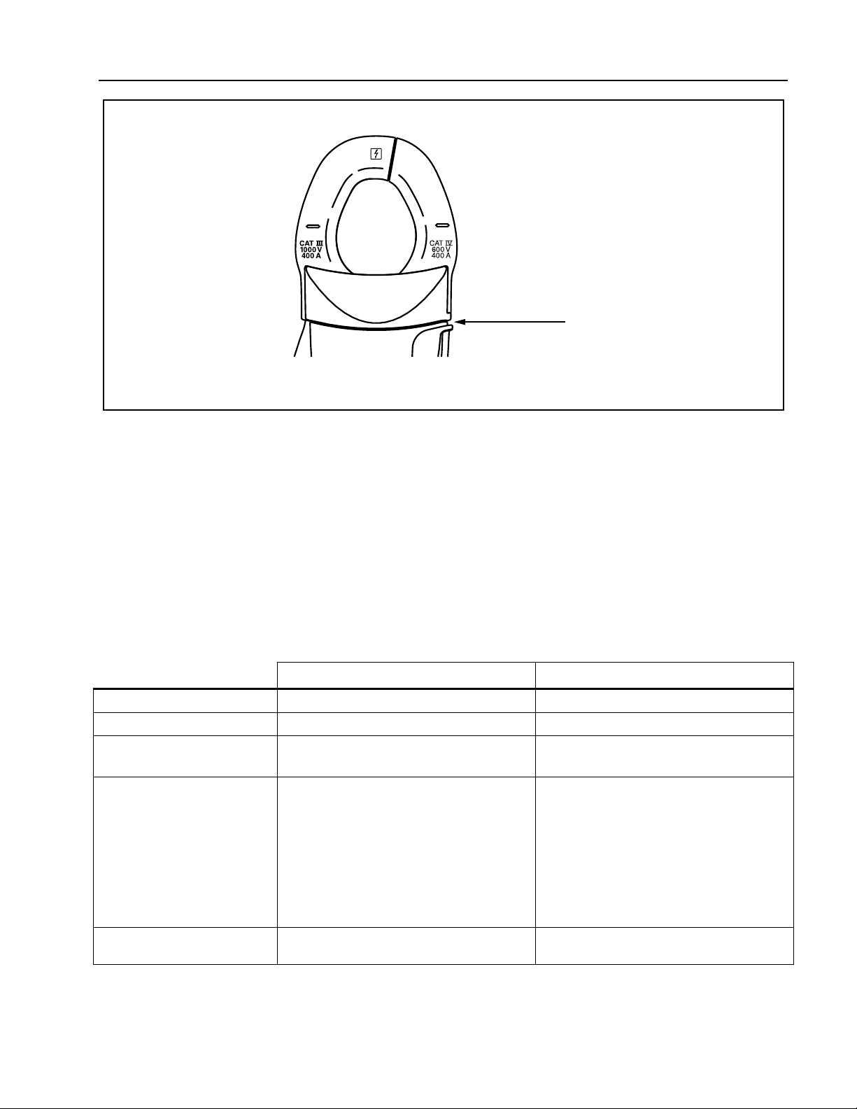
• Do not hold the Current Clamp anywhere beyond the tactile barrier, see
Figure 1.
• Before each use, inspect the Current Clamp. Look for cracks or missing
portions of the clamp housing or output cable insulation. Also look for
loose or weakened components. Pay particular attention to the insulation
surrounding the jaws.
XW Read First: Safety Information
• Never use the Current Clamp on a circuit with voltages higher than 1000 V
CAT III or 600 V CAT IV.
• CAT III equipment is designed to protect against transients in
equipment in fixed-equipment installations, such as distribution
panels, feeders and short branch circuits, and lighting systems in
large buildings.
• CAT IV equipment is designed to protect against transients from the
primary supply level, such as an electricity meter or an overhead or
underground utility service.
• Use extreme caution when working around bare conductors or bus bars.
Contact with the conductor could result in electric shock.
• Use caution when working with voltages above 60 V dc or 30 V ac. Such
voltages pose a shock hazard.
Electrical Symbols
The symbols in Table 1 appear in this document and on the Current Clamp.
Table 1. Electrical Symbols
Symbol Explanation
,
Application around and removal from hazardous live conductors is permitted.
2
T
W
X
)
P
Product is protected by double insulation.
Risk of Danger. Important information. See Instruction Sheet.
Hazardous voltage.
Conforms to relevant Canadian Standards Association directives.
Conforms to relevant European Union directives.
Page 3
AC Current Clamp
Tactile Barrier
Figure 1. Tactile Barrier
Safety Specifications
bbc03f.eps
Safety Specifications
Category Rating: CAT III 1000 V and CAT IV 600 V per EN61010-1, Pollution Degree 2
EMC: EN 61326-1, FCC for emission and immunity
): Tested to US and Canadian standards for compliance to UL61010-1 and CAN/CSA C22.2 No.
101.1:2004
P: IEC 61010-1 2
nd
Edition IEC 61010-02-032
Electrical Specifications
Reference Conditions: 23 ± 5 °C, 20 to 75 % RH; conductor centered in jaw opening; no DC component;
no adjacent conductor.
Measurement Range 0.5 A to 40 A 5 A to 400 A
Output 10 mV/A 1 mV/A
Accuracy
45 Hz to 400 Hz
Phase Shift:
(45 Hz to 400 Hz)
0.5 A to 1 A
1 A to 5 A
5 A to 10 A
10 A to 20 A
20 A to 40 A
40 A to 400 A
Crest Factor • 3 • 3 to 300 A
2 % + 0.015 A
Unspecified
4˚
3˚
3˚
2˚
NA
Typical Bandwidth: 5 Hz to 10 kHz
40 A Range 400 A Range
2 % + 0.04 A
NA
NA
Unspecified
2˚
2˚
1.5˚
• 2.5 to 400 A
Working Voltage: 1000 V ac rms, in compliance with EN61010
Common Mode Voltage: 1000 V ac rms from earth ground, in compliance with EN61010
3
Page 4

i400s
Calibration Information
Input Load Impedance (of host instrument): > 1 M Ω in parallel with up to 47 pF
Maximum Non-destructive Current: 1000 A
Duty Cycle: 0.5 A to 400 A continuous
Influence of Adjacent Conductor: < 9.0 mA/A
Influence of Conductor Position in Jaw Opening: ± 1.0 % of reading + 0.05 A
General Specifications
Output Cable Length: 2.5 m (8.2 ft)
Maximum Conductor Size: 32 mm (1.25 in)
Storage Temperature: -20 °C to 60 °C (-4 °F to 140 °F)
Operating Temperature: 0 °C to 50 °C (32 °F to 122 °F)
Relative Humidity: 10 °C to 30 °C: 95 % (50 °F to 86 °F)
30 °C to 40 °C: 75 % (86 °F to 104 °F)
40 °C to 50 °C: 45 % (104 °F to 122 °F)
Temperature Coefficient: 0.01 % X (specified accuracy)/ °C (< 18 °C or > 28 °C)
0.01 % X (specified accuracy)/ °F (< 64.4 °F or > 82.4 °F )
Altitude:
Operating: 2000 m; 2000 m to 4000 m, derate category rating to 1000 V CAT II/600 V CAT III
Non-operating: 12000 m
Dimensions: (LxWxH) 150 x 70 x 30 mm (5.09 x 2.75 x 1.18 in)
Weight: 114 g (4 oz)
Maintenance
XW Warning
To avoid possible electric shock or personal injury:
• Before each use, inspect the Current Clamp. Look for cracks or missing
portions of the clamp housing and output cable insulating cover and for
loose or weakened components. Pay particular attention to the insulation
surrounding the clamp jaws.
• Do not use a damaged Current Clamp. If a clamp is damaged, tape it shut to
prevent unintended operation. A damaged clamp under warranty will be
promptly repaired or replaced (at Fluke’s discretion) and returned at no
extra charge.
If the Current Clamp does not work or perform properly, use the following steps to help isolate the
problem:
1. Inspect the jaw-mating surface for cleanliness. If any foreign material is present, the jaw will not
close properly and measurement errors will result.
2. Verify that the function selection and range on the Multimeter are correct and adjusted to the
sensitivity of the Current Clamp.
4
Page 5

AC Current Clamp
Performance Tests
Cleaning
Periodically wipe the case with a damp cloth and mild detergent.
W Caution
To avoid damaging the Current Clamp, do not use abrasives or solvents to
clean the clamp.
Open the jaws and wipe the magnetic pole pieces with a lightly oiled cloth. Do
not allow rust or corrosion to form on the magnetic core ends.
Performance Tests
XWWarning
To avoid electric shock or injury, do not perform the performance tests or
calibration procedures unless you are qualified to do so.
The information provided in this manual is for the use of qualified personnel
only.
The following performance tests verify the complete operation of the Current Clamp and checks the
accuracy of each function against the Clamp’s specifications. If the Current Clamp fails any part of the
test, calibration adjustment and/or repair is indicated.
In the performance tests, the Current Clamp is referred to as the unit under test (UUT).
Required test equipment is defined in Table 2.
Table 2. Required Test Equipment
Equipment Required Characteristics Recommended Model
Calibrator AC Current: 0 - 8 A
Max. Accuracy: 0.15 %
Frequency: 45 Hz - 400 Hz
Multimeter AC Voltage: 20 mV - 400 mV
Accuracy: 0.45 %
Frequency: 45 Hz - 400 Hz
Toroid Coil Turns: 50 Fluke 5500A/Coil
Fluke 5520A Multi-Product Calibrator
Fluke-45 Digital Multimeter (DMM)
Current Accuracy Tests
1. Connect the equipment as shown in Figure 2.
2. Center the UUT jaws around the 5500A/Coil windings.
3. Set the UUT range and 5520A output as called out in Table 3. Check that the Multimeter readings are
within the specified limits in Table 3.
5
Page 6

i400s
Calibration Information
Table 3. Accuracy Tests
i400s Range Nominal Value
5520A Output
LCOMP = ON
Multimeter Reading Limits
Lower Upper
1 mV/A 20 A, 50 Hz 0.4 A, 50 Hz 19.56 20.44
1 mV/A 20 A, 400 Hz 0.4 A, 400 Hz 19.56 20.44
1 mV/A 400 A, 50 Hz 8.0 A, 50 Hz 391.96 408.04
1 mV/A 400 A, 100 Hz 8.0 A, 100 Hz 391.96 408.04
10 mV/A 2 A, 50 Hz 40 mA, 50 Hz 19.45 20.55
10 mV/A 2 A, 400 Hz 40 mA, 400 Hz 19.45 20.55
10 mV/A 40 A, 50 Hz 0.8 A, 50 Hz 391.85 408.15
10 mV/A 40 A, 100 Hz 0.8 A, 100 Hz 391.85 408.15
6
Figure 2. Current Accuracy Test Connections
bbc01f.eps
Page 7

AC Current Clamp
Calibration Adjustment
Calibration Adjustment
1. Using the equipment connections shown in Figure 2, set the 5520A output for 2 A, 45 Hz.
2. Referring to Figure 3, slide the rubber boot on the UUT handle back to access the adjustment point,
VR1.
3. Using a small flat-head screwdriver, adjust VR1 for a meter reading of 99.9 mV to 100.1 mV.
VR1
Figure 3. i400s Calibration Point
bbc02f.eps
User-Replaceable Parts
The Current Clamp contains no user-replaceable parts. The following user documentation is available for
this product.
Description Part No Qty
i400s Instruction Sheet 2282671 1
i400s Calibration Information
(this document)
2414327 1
7
Page 8

i400s
Calibration Information
LIMITED WARRANTY AND LIMITATION OF LIABILITY
Each Fluke product is warranted to be free from defects in material and workmanship under normal use and service. The warranty period
is one year and begins on the date of shipment. Parts, product repairs, and services are warranted for 90 days. This warranty extends only
to the original buyer or end-user customer of a Fluke authorized reseller, and does not apply to fuses, disposable batteries, or to any
product which, in Fluke's opinion, has been misused, altered, neglected, contaminated, or damaged by accident or abnormal conditions of
operation or handling. Fluke warrants that software will operate substantially in accordance with its functional specifications for 90 days
and that it has been properly recorded on non-defective media. Fluke does not warrant that software will be error free or operate without
interruption.
Fluke authorized resellers shall extend this warranty on new and unused products to end-user customers only but have no authority to
extend a greater or different warranty on behalf of Fluke. Warranty support is available only if product is purchased through a Fluke
authorized sales outlet or Buyer has paid the applicable international price. Fluke reserves the right to invoice Buyer for importation costs
of repair/replacement parts when product purchased in one country is submitted for repair in another country.
Fluke's warranty obligation is limited, at Fluke's option, to refund of the purchase price, free of charge repair, or replacement of a defective
product which is returned to a Fluke authorized service center within the warranty period.
To obtain warranty service, contact your nearest Fluke authorized service center to obtain return authorization information, then send the
product to that service center, with a description of the difficulty, postage and insurance prepaid (FOB Destination). Fluke assumes no risk
for damage in transit. Following warranty repair, the product will be returned to Buyer, transportation prepaid (FOB Destination). If Fluke
determines that failure was caused by neglect, misuse, contamination, alteration, accident, or abnormal condition of operation or handling,
including overvoltage failures caused by use outside the product’s specified rating, or normal wear and tear of mechanical components,
Fluke will provide an estimate of repair costs and obtain authorization before commencing the work. Following repair, the product will be
returned to the Buyer transportation prepaid and the Buyer will be billed for the repair and return transportation charges (FOB Shipping
Point).
THIS WARRANTY IS BUYER'S SOLE AND EXCLUSIVE REMEDY AND IS IN LIEU OF ALL OTHER WARRANTIES, EXPRESS OR
IMPLIED, INCLUDING BUT NOT LIMITED TO ANY IMPLIED WARRANTY OF MERCHANTABILITY OR FITNESS FOR A PARTICULAR
PURPOSE. FLUKE SHALL NOT BE LIABLE FOR ANY SPECIAL, INDIRECT, INCIDENTAL, OR CONSEQUENTIAL DAMAGES OR
LOSSES, INCLUDING LOSS OF DATA, ARISING FROM ANY CAUSE OR THEORY.
Since some countries or states do not allow limitation of the term of an implied warranty, or exclusion or limitation of incidental or
consequential damages, the limitations and exclusions of this warranty may not apply to every buyer. If any provision of this Warranty is
held invalid or unenforceable by a court or other decision-maker of competent jurisdiction, such holding will not affect the validity or
enforceability of any other provision.
Fluke Corporation
P.O. Box 9090
Everett, WA 98206-9090
U.S.A.
Fluke Europe B.V.
P.O. Box 1186
5602 BD Eindhoven
The Netherlands
11/99
To register your product online, visit register.fluke.com
8
 Loading...