

Page 1

80 Series III
Multimeters
Users Manual
®
October 1997 Rev.5, 12/03
1997-2003 Fluke Corporation, All rights reserved.
All product names are trademarks of their respective companies.
Page 2

Lifetime Limited Warranty
Each Fluke 20, 70, 80, 170 and 180 Series DMM will be free f rom def ects in material and workmanship for its lifetime. As used herein,
“lifetime” is defined as seven years after Fluk e di scontinues manufacturi ng the product, but the warranty peri od shall be at least ten years from
the date of purchase. This warranty does not cover fuses, disposable batteries , damage from neglect, misuse, contamination, alteration,
accident or abnormal conditi ons of operation or handling, including failures caused by use out s i de of the product’s speci f i cations, or normal
wear and tear of mechanical components. This warranty cov ers the original purchaser only and is not transferable.
For ten years from the date of purchase, this warranty also covers the LCD. Thereafter, for the lifetime of the DMM, Fluke will replace the
LCD for a fee based on then current component acquisition cost s.
To establish original ownership and prove date of purchase, please c om pl ete and return the registration card accompanying the product, or
register your product on http://www.fluke.com. Fluke will, at its option, repair at no charge, replace or refund the purchase price of a
defective product purchased through a Fluke authorized sales outlet and at the applicable int ernational price. Fluke reserv es the right to
charge for importation costs of repair/replacement part s if the product purchased i n one c ountry is sent for repair elsewhere.
If the product is defective, contact y our nearest Fluke authorized serv i ce center to obtain return authoriz ation information, then s end t he
product to that service center, with a description of the difficulty, postage and insurance prepaid (FOB Destination). Fluke assumes no risk
for damage in transit. Fluke will pay return trans portation for product repaired or replaced in-warranty. B ef ore making any non-warranty
repair, Fluke will estimate cost and obt ain authorization, then invoice you for repair and return transportation.
THIS WARRANTY IS Y O UR ONLY REMEDY. NO OTHER WARRANT IES, SUCH AS FI T NESS FOR A PARTICULAR PURPOSE, ARE
EXPRESSED OR IMPLIED. FLUKE SHALL NOT BE LIABLE FOR ANY SPECIAL, INDIRECT, INCIDENTAL OR CONSEQUENTIAL
DAMAGES OR LOSSES, INCLUDING LOSS OF DATA, ARISING FROM ANY CAUSE OR THEORY. AUTHORIZED RESELLERS ARE
NOT AUTHORIZED TO EXTEND ANY DI FFERENT WARRANTY ON FLUKE’S B E HA LF. Since some states do not allow the exclusi on or
limitation of an implied warranty or of incidental or cons equential damages, this limitation of liability may not apply to you. If any provi sion of
this warranty is held invalid or unenforceable by a court or other decision-maker of competent jurisdiction, such holding will not affect the
validity or enforceability of any other provision.
Fluke Corporation Fluke Europe B.V.
P.O. Box 9090 P.O. Box 1186
Everett WA 5602 B.D. Eindhoven
2/02 98206-9090 The Netherlands
Page 3

Table of Contents
Title Page
Introduction....................................................................................................................1
Safety Information......................................................................................................... 1
Your Meter’s Features................................................................................................... 4
Power-Up Options.................................................................................................... 11
Automatic Power-Off................................................................................................. 11
Input Alert™ Feature................................................................................................ 12
Making Measurements.................................................................................................. 12
Measuring AC and DC Voltage................................................................................. 12
Testing for Continuity................................................................................................ 14
Measuring Resistance.............................................................................................. 16
Using Conductance for High Resistance or Leakage Tests ..................................... 18
Measuring Capacitance............................................................................................ 18
Testing Diodes.......................................................................................................... 21
Measuring AC or DC Current.................................................................................... 22
Measuring Frequency............................................................................................... 25
Measuring Duty Cycle............................................................................................... 27
Determining Pulse Width.......................................................................................... 28
i
Page 4

80 Series III
Users Manual
Analog Bar Graph.......................................................................................................... 28
Model 87 Bar Graph.................................................................................................. 28
Models 83 and 85 Bar Graph.................................................................................... 29
4-1/2 Digit Mode (Model 87).......................................................................................... 29
MIN MAX Recording Mode............................................................................................ 30
Touch Hold ® Mode....................................................................................................... 32
Relative Mode................................................................................................................ 32
Zoom Mode (Models 83 and 85)............................................................................... 32
Uses for the Zoom Mode (Models 83 and 85)........................................................... 33
Maintenance.................................................................................................................. 33
General Maintenance................................................................................................ 33
Testing the Fuses...................................................................................................... 34
Replacing the Battery................................................................................................ 35
Replacing the Fuses ................................................................................................. 35
Service and Parts........................................................................................................... 36
Specifications................................................................................................................. 41
ii
Page 5

List of Tables
Table Title Page
1. International Electrical Symbols......................................................................................... 2
2. Inputs................................................................................................................................. 4
3. Rotary Switch Positions ..................................................................................................... 5
4. Pushbuttons....................................................................................................................... 6
5. Display Features................................................................................................................ 9
6. Estimating Capacitance Values Over 5 Microfarads.......................................................... 20
7. Functions and Trigger Levels for Frequency Measurements............................................. 26
8. MIN MAX Functions........................................................................................................... 31
9. Replacement Parts.............................................................................................................38
10. Accessories........................................................................................................................ 40
11. Models 85 and 87 AC Voltage Function Specifications...................................................... 42
12. Model 83 AC Voltage Function Specifications................................................................... 43
13. DC Voltage, Resistance, and Conductance Function Specifications................................. 44
14. Current Function Specifications......................................................................................... 45
15. Capacitance and Diode Function Specifications................................................................ 47
16. Frequency Counter Specifications..................................................................................... 47
17. Frequency Counter Sensitivity and Trigger Levels............................................................. 48
18. Electrical Characteristics of the Terminals......................................................................... 49
19. MIN MAX Recording Specifications................................................................................... 50
iii
Page 6

80 Series III
Users Manual
iv
Page 7

List of Figures
Figure Title Page
1. Display Features (Model 87 Shown).......................................................... 8
2. Measuring AC and DC Voltage.................................................................. 13
3. Testing for Continuity................................................................................. 15
4. Measuring Resistance............................................................................... 17
5. Measuring Capacitance............................................................................. 19
6. Testing a Diode......................................................................................... 21
7. Measuring Current..................................................................................... 23
8. Components of Duty Cycle Measurements ............................................... 27
9. Testing the Current Fuses......................................................................... 34
10. Battery and Fuse Replacement................................................................. 37
11. Replaceable Parts..................................................................................... 39
v
Page 8

80 Series III
Users Manual
vi
Page 9

Introduction
Introduction
WWarning
Read "Safety Information" before you use the
meter.
Except where noted, the descriptions and instructions in
this manual apply to Series III Models 83, 85, 87, and
87/E multimeters. Model 87 is shown in all illustrations.
Safety Information
This meter complies with:
• EN61010.1:1993
• ANSI/ISA S82.01-1994
• CAN/CSA C22.2 No. 1010.1-92
• 1000 V Overvoltage Category III, Pollution Degree 2
• UL3111-1
Use the meter only as specified in this manual, otherwise
the protection provided by the meter may be impaired.
In this manual, a Warning identifies conditions and
actions that pose hazards to the user. A Caution
identifies conditions and actions that may damage the
meter or the equipment under test.
International symbols used on the meter and in this
manual are explained in Table 1.
WWarning
To avoid possible electric shock or personal
injury, follow these guidelines:
• Do not use the meter if it is damaged.
Before you use the meter, inspect the
case. Look for cracks or missing plastic.
Pay particular attention to the insulation
surrounding the connectors.
• Make sure the battery door is closed and
latched before you operate the meter.
• Replace the battery as soon as the
battery indicator (M) appears.
1
Page 10
80 Series III
Users Manual
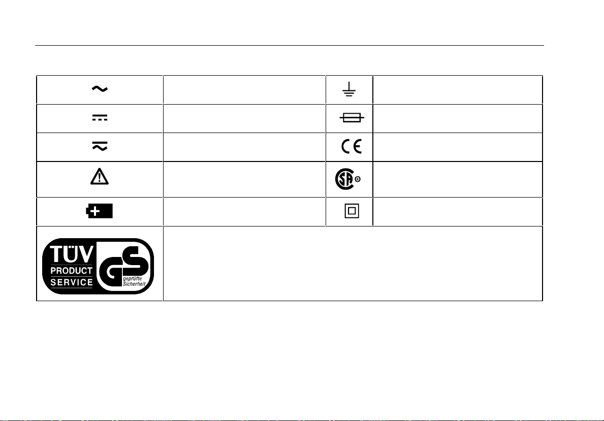
Table 1. International Electrical Symbols
AC (Alternating Current) Earth ground
DC (Direct Current) Fuse
AC or DC Conforms to European Union directives
Refer to the manual for information
about this feature.
Battery Double insulated
Inspected and licensed by TÜV Product Services.
Conforms to relevant Canadian
Standards Association directives
2
Page 11

Safety Information
• Remove test leads from the meter before
you open the battery door.
• Inspect the test leads for damaged
insulation or exposed metal. Check the
test leads for continuity. Replace
damaged test leads before you use the
meter.
• Do not use the meter if it operates
abnormally. Protection may be impaired.
When in doubt, have the meter serviced.
• Do not operate the meter around
explosive gas, vapor, or dust.
• Use only a single 9 V battery, properly
installed in the meter case, to power the
meter.
• When servicing the meter, use only
specified replacement parts.
Caution
To avoid possible damage to the meter or to
the equipment under test, follow these
guidelines:
• Disconnect circuit power and discharge
all high-voltage capacitors before testing
resistance, continuity, diodes, or
capacitance.
• Use the proper terminals, function, and
range for your measurements.
• Before measuring current, check the
meter’s fuses. (See "Testing the Fuses".)
3
Page 12

80 Series III
Users Manual
To protect yourself, use the following guidelines:
• Use caution when working with voltages above 30 V
ac rms, 42 V ac peak, or 60 V dc. Such voltages
pose a shock hazard.
• When using the probes, keep your fingers behind the
finger guards.
• Connect the common test lead before you connect
the live test lead. When you disconnect test leads,
disconnect the live test lead first.
• Avoid working alone.
• When measuring current, turn off circuit power
before connecting the meter in the circuit. Remember
to place the meter in series with the circuit.
Your Meter’s Features
Tables 2 through 5 briefly describe your meter’s features
and give page numbers where you can find more detailed
information about the features.
Table 2. Inputs
Terminal Description Page
A Input for 0 A to 10.00 A
current measurements
mA µA Input for 0 µA to 400 mA
current measurements
COM Return terminal for all
measurements
V eG Input for voltage,
continuity, resistance,
diode, capacitance,
frequency, and duty
cycle measurem ents
22
22
NA
V: 12
e: 16
G: 21
E:18
Frequency: 25
Duty cycle: 27
4
Page 13

Your Meter’s Features
Table 3. Rotary Switch Positions
Switch Position Function Page
K AC voltage measurement 12
L DC voltage measurement 12
d
mV
400 mV dc voltage range 12
ReE R Continuity test 14
e Resistance measurement 16
E Capacitance measurement 18
G Diode test 21
mA
DC or AC current measurements from 0 mA to 10.00 A 22
A
µA DC or AC current measurements from 0 µA to 4000 µA22
5
Page 14

80 Series III
Users Manual
Table 4. Pushbuttons
Button Function Button Function Page
U
(Blue
button)
M
K
I
6
ReE
mA/A, µA
Power-up
Any switch
position
Power-up
Any switch
position
Power-up For servicing purposes only. NA
Any switch
position
MIN MAX
recording
Frequency
counter
Selects capacitance.
Switches between dc and ac current.
Disables automatic power-off feature.
Starts recording of minimum and maximum values. Steps the display through
MIN, MAX, AVG (average), and present readings.
Enables high-accuracy 1-second response time for MIN MAX recording.
Switches between the ranges available for the selected function. To return to
autoranging, hold the button down for 1 second.
Manually selecting a range causes the meter to exit the Touch Hold®, MIN
MAX, and REL (relative) modes.
Touch Hold captures the present reading on the display. When a new, stable
reading is detected, the meter beeps and displays the new reading.
Stops and starts recording without erasing recorded values.
Stops and starts the frequency counter.
18
22
11
30
30
See ranges in
specifications.
32
30
25
Page 15

Your Meter’s Features
Table 4. Pushbuttons (cont)
Button Function Button Function Page
b Model 87:
yellow button
b Models 83,
85: gray
button
T
C
(Relative
mode)
F
Any switch
position
Continuity
ReE
MIN MAX
recording
Power-up
Any switch
position
Power-up
Any switch
position
Power-up
Turns the backlight on and off.
For Model 87, hold the yellow button down for one second to enter the
4-1/2 digit mode. To return to the 3-1/2 digit mode, hold the button down
only until all display segments turn on (about one second).
Turns the continuity beeper on and off.
On Model 87, switches between 250 µs and 100 ms or 1 s response
times.
Disables the beeper for all functions.
Stores the present reading as a reference for subsequent readings. The
display is zeroed, and the stored reading is subtracted from all
subsequent readings.
For Models 83 and 85, enables zoom mode for the bar graph.
Starts the frequency counter.
Press again to enter duty cycle mode.
Provides >4000 MΩ input impedance for the 400 mV dc range.
NA
29
14
30
NA
32
32
25
27
NA
7
Page 16
80 Series III
Users Manual
9
6
5
4
3
7
8
10
10
2
1
12
13
10
11
iy1f.eps
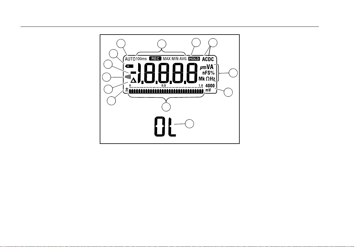
Figure 1. Display Features (Model 87 Shown)
8
Page 17

Your Meter’s Features
Table 5. Display Features
Number Feature Indication Page
A
B
C
±
Q
S
D
-
E The battery is low. WWarning: To avoid false readings, which could lead
F
G
AUTO
100 ms
MAX MIN AVG
Polarity indicator for the analog bar graph. 28
Relative (REL) mode is active. 32
The continuity beeper is on. 14
Indicates negative readings. In relative mode, this sign indicates that the
present input is less than the stored reference.
to possible electric shock or personal injury, replace the battery as soon
as the battery indicator appears.
The meter is in autorange mode and automatically selects the range with the
best resolution.
Indicators for minimum-maximum recording mode. 30
32
35
NA
H Touch Hold is active. 32
I AC DC Indicator for ac or dc voltage or current. AC voltage and current is displayed as
an rms (root mean square) value.
12, 22
9
Page 18

80 Series III
Users Manual
Table 5. Display Features (continued)
Number Feature Indication Page
J A, µA, mA A: Amperes (amps). The unit of current.
µA: Microamp. 1 x 10
mA: Milliamp. 1 x 10
-6
or 0.000001 amperes.
-3
or 0.001 amperes.
V, mV V: Volts. The unit of voltage.
mV: Millivolt. 1 x 10
-3
or 0.001 volts.
µF, nF F: Farad. The unit of capacitance.
µF: Microfarad. 1 x 10
nF: Nanofarad. 1 x 10
-6
or 0.000001 farads.
-9
or 0.000000001 farads.
nS S: Siemen. The unit of conductance.
nS: Nanosiemen. 1 x 10
-9
or 0.000000001 siemens.
% Percent. Used for duty cycle measur ements. 27
e, Me, ke Ω: Ohm. The unit of resistance.
MΩ: Megohm. 1 x 10
kΩ: Kilohm. 1 x 10
6
or 1,000,000 ohms.
3
or 1000 ohms.
Hz, kHz, MHz Hz: Hertz. The unit of frequency.
kHz: Kilohertz. 1 x 10
MHz: Megahertz. 1 x 10
10
3
or 1000 hertz.
6
or 1,000,000 hertz.
22
12
18
18
16
25
Page 19

Your Meter’s Features
Table 5. Display Features (continued)
Number Feature Indication Page
K 4000 mV Displays the currently selected range. See specifications
for ranges for each
function.
L Analog bar graph Provides an analog indication of the present inputs. 28
M
0L
The input (or the relative value when in relative mode) is too large
for the selected range. For duty cycle measurements OL is
displayed when the input signal stays high or low.
Power-Up Options
Holding a button down while turning the meter on
activates a power-up option. Table 4 includes the powerup options available. These options are also listed on the
back of the meter.
Duty cycle: 27
Automatic Power-Off
The meter automatically turns off if you do not turn the
rotary switch or press a button for 30 minutes. To disable
automatic power-off, hold down the blue button while
turning the meter on. Automatic power-off is always
disabled in MIN MAX recording mode.
11
Page 20

80 Series III
Users Manual
Input Alert™ Feature
If a test lead is plugged into the mA/µA or A terminal, but
the rotary switch is not correctly set to the mA/µA or A
position, the beeper warns you by making a chirping
sound. This warning is intended to stop you from
attempting to measure voltage, continuity, resistance,
capacitance, or diode values when the leads are plugged
into a current terminal.
parallel with) a powered circuit when a lead is plugged into
a current terminal can damage the circuit you are testing
and blow the meter’s fuse.
resistance through the meter’s current terminals is very
low, so the meter acts like a short circuit.
Placing the probes across (in
This can happen because the
Making Measurements
The following sections describe how to take
measurements with your meter.
Measuring AC and DC Voltage
Voltage is the difference in electrical potential between
two points. The polarity of ac (alternating current) voltage
varies over time, while the polarity of dc (direct current)
voltage is constant over time. The meter presents ac
voltage values as rms (root mean square) readings. The
rms value is the equivalent dc voltage that would produce
the same amount of heat in a resistance as the measured
sinewave voltage. Models 85 and 87 feature true rms
readings, which are accurate for other wave forms (with
no dc offset) such as square waves, triangle waves, and
staircase waves.
The meter’s voltage ranges are 400 mV, 4 V, 40 V, 400 V,
and 1000 V. To select the 400 mV dc range, turn the
rotary switch to mV.
To measure ac or dc voltage, set up and connect the
meter as shown in Figure 2.
12
Page 21

The following are some tips for measuring voltage:
• When you measure voltage, the meter acts
approximately like a 10 MΩ (10,000,000 Ω)
impedance in parallel with the circuit. This loading
effect can cause measurement errors in highimpedance circuits. In most cases, the error is
negligible (0.1% or less) if the circuit impedance is
10 kΩ (10,000 Ω) or le ss.
• For better accuracy when measuring the dc offset of
an ac voltage, measure the ac voltage first. Note the
ac voltage range, then manually select a dc voltage
range equal to or higher than the ac range. This
procedure improves the accuracy of the dc
measurement by ensuring that the input protection
circuits are not activated.
Making Measurements
AC Voltage
TRUE RMS MULTIMETER
87
III
H
MIN MAX RANGE HOLD
HzREL
PEAK MIN MAX
41/2 DIGITS
1 Second
mV
mA
V
A
µA
V
V
OFF
mA µA
A COM
400mA MAX
FUSED
10A MAX
FUSED
!
V
!
CAT II
1000V MAX
Switch Box
DC Voltage
TRUE RMS MULTIMETER
87
III
H
MIN MAX RANGE HOLD
HzREL
PEAK MIN MAX
41/2 DIGITS
1 Second
mV
mA
V
A
V
V
OFF
mA µA
A COM
400mA MAX
FUSED
10A MAX
FUSED
!
µA
V
!
CAT II
1000V MAX
+
Figure 2. Measuring AC and DC Voltage
iy2f.eps
13
Page 22

80 Series III
Users Manual
Testing for Continuity
Caution
To avoid possible damage to the meter or to
the equipment under test, disconnect circuit
power and discharge all high-voltage
capacitors before testing for continuity.
Continuity is the presence of a complete path for current
flow. The continuity test features a beeper that sounds if a
circuit is complete. The beeper allows you to perform
quick continuity tests without having to watch the display.
To test for continuity, set up the meter as shown in
Figure 3.
Press Tto turn the continuity beeper on or off.
The continuity function detects intermittent opens and
shorts lasting as little as 1 millisecond (0.001 second).
These brief contacts cause the meter to emit a short beep.
14
Page 23

For in-circuit tests, turn circuit power off.
Making Measurements
4 1/2 DIGITS
1 Seconds
V
OFF
MIN MAX RANGE HOLD
PEAK MIN MAX
mV
V
10A MAX
FUSED
87
400mA MAX
FUSED
TRUE RMS MULTIMETER
III
!
Activates
continuity
H
HzREL
mA
A
µA
!
CAT II
1000V MAX
beeper
ON
(closed)
87
MIN MAX RANGE HOLD
PEAK MIN MAX4 1/2 DIGITS
1 Seconds
mV
V
V
OFF
mA µA
A COM
400mA MAX
FUSED
10A MAX
FUSED
TRUE RMS MULTIMETER
III
!
H
HzREL
mA
A
µA
V
!
CAT II
1000V MAX
OFF
(open)
iy4f.eps
Figure 3. Testing for Continuity
15
Page 24

80 Series III
Users Manual
Measuring Resistance
Caution
To avoid possible damage to the meter or to
the equipment under test, disconnect circuit
power and discharge all high-voltage
capacitors before measuring resistance.
Resistance is an opposition to current flow. The unit of
resistance is the ohm (Ω). The meter measures resistance
by sending a small current through the circuit. Because
this current flows through all possible paths between the
probes, the resistance reading represents the total
resistance of all paths between the probes.
The meter’s resistance ranges are 400 Ω, 4 kΩ, 40 kΩ,
400 kΩ, 4 MΩ, and 40 MΩ.
To measure resistance, set up the meter as shown in
Figure 4.
The following are some tips for measuring resistance:
• Because the meter’s test current flows through all
possible paths between the probe tips, the measured
value of a resistor in a circuit is often different from
the resistor’s rated value.
• The test leads can add 0.1 Ω to 0.2 Ω of error to
resistance measurements. To test the leads, touch
the probe tips together and read the resistance of the
leads. If necessary, you can use the relative (REL)
mode to automatically subtract this value.
• The resistance function can produce enough voltage
to forward-bias silicon diode or transistor junctions,
causing them to conduct. To avoid this, do not use
the 40 MΩ range for in-circuit resistance
measurements.
16
Page 25

Making Measurements
4 1/2 DIGITS
1 Seconds
V
V
OFF
A
10A MAX
FUSED
TRUE RMS MULTIMETER
87
III
MIN MAX RANGE HOLD
PEAK MIN MAX
mV
COM
mA µA
400mA MAX
FUSED
!
In-Circuit Resistance Measurements
Circuit Power
OFF
H
HzREL
mA
A
µA
V
!
CAT II
1000V MAX
Figure 4. Measuring Resistance
Isolating a Potentiometer
1
2
3
Disconnect
1
2
3
Isolating a Resistor
Disconnect
iy6f.eps
17
Page 26

80 Series III
Users Manual
Using Conductance for High Resistance or Leakage Tests
Conductance, the inverse of resistance, is the ability of a
circuit to pass current. High values of conductance
correspond to low values of resistance.
The unit of conductance is the Siemen (S). The meter’s
40 nS range measures conductance in nanosiemens
(1 nS = 0.000000001 Siemens). Because such small
amounts of conductance correspond to extremely high
resistance, the nS range lets you determine the
resistance of components up to 100,000 MΩ, or
100,000,000,000 Ω (1/1 nS = 1,000 MΩ).
To measure conductance, set up the meter as shown for
measuring resistance (Figure 4); then press Kuntil
the nS indicator appears on the display.
The following are some tips for measuring conductance:
• High-resistance readings are susceptible to electrical
noise. To smooth out most noisy readings, enter the
MIN MAX recording mode; then scroll to the average
(AVG) reading.
• There is normally a residual conductance reading
with the test leads open. To ensure accurate
readings, use the relative (REL) mode to subtract the
residual value.
Measuring Capacitance
Caution
To avoid possible damage to the meter or to
the equipment under test, disconnect circuit
power and discharge all high-voltage
capacitors before measuring capacitance.
Use the dc voltage function to confirm that
the capacitor is discharged.
Capacitance is the ability of a component to store an
electrical charge. The unit of capacitance is the farad (F).
Most capacitors are in the nanofarad to microfarad range.
18
Page 27

The meter measures capacitance by charging the
capacitor with a known current for a known period of time,
measuring the resulting voltage, then calculating the
capacitance. The measurement takes about 1 second per
range. The capacitor charge can be up to 1.2 V.
The meter’s capacitance ranges are 5 nF, 0.05 µF,
0.5 µF, and 5 µF.
To measure capacitance, set up the meter as shown in
Figure 5.
The following are some tips for measuring capacitance:
• To speed up measurements of similar values, press
Kto manually select the proper range.
• To improve the accuracy of measurements less than
5 nF, use the relative (REL) mode to subtract the
residual capacitance of the meter and leads.
4 1/2 DIGITS
1 Seconds
V
V
OFF
A
10A MAX
FUSED
TRUE RMS MULTIMETER
87
III
MIN MAX RANGE HOLD
PEAK MIN MAX
mV
COM
mA µA
400mA MAX
FUSED
!
+
+
+
+
+
+
+
+
Making Measurements
Select
µ
nF
Capacitance
H
HzREL
mA
A
µA
V
!
CAT II
1000V MAX
+
Figure 5. Measuring Capacitance
iy10f.eps
19
Page 28

80 Series III
Users Manual
• To estimate capacitance values above 5 µF, use the
current supplied by the meter’s resistance function,
as follows:
1. Set up the meter to measure resistance.
2. Press Kto select a range based on the
value of capacitance you expect to measure
(refer to Table 6.)
3. Discharge the capacitor.
4. Place the meter’s leads across the capacitor;
then time how long it takes for the display to
reach OL.
5. Multiply the charge time from step 4 by the
appropriate value in the µF/second of Charge
Time column in 6. The result is the estimated
capacitance value in microfarads (µF).
Table 6. Estimating Capacitance Values Over
5 Microfarads
µF/second
of Charge
Time
Expected Capacitance
Suggested
Range*
Up to 10 µF4 Me 0.3
11 µF to 100 µF 400 ke 3
101 µF to 1000 µF 40 ke 30
1001 µF to 10,000 µF4 ke 300
10,000 µF to 100,000 µF 400 e 3000
*These ranges keep the full-charge ti me between 3.7 seconds
and 33.3 seconds for the expec ted capacitance values. If the
capacitor charges too quic kly for you to time, select the next
higher resistance range.
20
Page 29

Making Measurements
Testing Diodes
Caution
To avoid possible damage to the meter or to
the equipment under test, disconnect circuit
power and discharge all high-voltage
capacitors before testing diodes.
Use the diode test to check diodes, transistors, silicon
controlled rectifiers (SCRs), and other semiconductor
devices. This function tests a semiconductor junction by
sending a current through the junction, then measuring
the junction’s voltage drop. A good silicon junction drops
between 0.5 V and 0.8 V.
To test a diode out of a circuit, set up the meter as shown
in Figure 6. For forward-bias readings on any
semiconductor component, place the red test lead on the
component’s positive terminal and place the black lead
on the component’s negative terminal.
In a circuit, a good diode should still produce a forwardbias reading of 0.5 V to 0.8 V; however, the reverse-bias
reading can vary depending on the resistance of other
pathways between the probe tips.
TRUE RMS MULTIMETER
87
III
Typical
Reading
H
MIN MAX RANGE HOLD
HzREL
PEAK MIN MAX
4 1/2 DIGITS
1 Seconds
mV
mA
V
A
µA
V
OFF
V
COM
A
mA µA
!
400mA MAX
CAT II
FUSED
1000V MAX
10A MAX
FUSED
!
TRUE RMS MULTIMETER
87
III
H
MIN MAX RANGE HOLD
HzREL
PEAK MIN MAX
4 1/2 DIGITS
1 Seconds
mV
mA
V
A
µA
V
OFF
V
COM
A
mA µA
!
400mA MAX
CAT II
FUSED
1000V MAX
10A MAX
FUSED
!
Figure 6. Testing a Diode
Forward Bias
+
Reverse Bias
+
iy9f.eps
21
Page 30

80 Series III
Users Manual
Measuring AC or DC Current
WWarning
Never attempt an in-circuit current
measurement where the open-circuit
potential to earth is greater than 1000 V. You
may damage the meter or be injured if the
fuse blows during such a measurement.
Caution
To avoid possible damage to the meter or to
the equipment under test, check the meter’s
fuses before measuring current. Use the
proper terminals, function, and range for
your measurement. Never place the probes
across (in parallel with) any circuit or
component when the leads are plugged into
the current terminals.
Current is the flow of electrons through a conductor. To
measure current, you must break the circuit under test,
then place the meter in series with the circuit.
The meter’s current ranges are 400 µA, 4000 µA,
40 mA, 400 mA, 4000 mA, and 10 A. AC current is
displayed as an rms value.
To measure current, refer to Figure 7 and proceed as
follows:
1. Turn off power to the circuit. Discharge all high-
voltage capacitors.
2. Insert the black lead into the COM terminal. For
currents between 4 mA and 400 mA, insert the red
lead into the mA/µA terminal. For currents above
400 mA, insert the red lead into the A terminal.
Note
To avoid blowing the meter’s 400 mA fuse, use
µ
the mA/
A terminal only if you are sure the
current is less than 400 mA.
22
Page 31

Making Measurements
4 1/2 DIGITS
1 Seconds
A
V
V
OFF
10A MAX
FUSED
TRUE RMS MULTIMETER
87
III
AC DC
MIN MAX RANGE HOLD
PEAK MIN MAX
mV
mA µA
COM V
400mA MAX
FUSED
!
1000V MAX
Circuit Power:
OFF to connect meter.
1
Total current to circuit
ON for measurement.
OFF to disconnect meter.
4
5
H
HzREL
mA
A
µA
mA
µA
3
A
Current through one component
2
!
CAT II
5
Figure 7. Measuring Current
iy7f.eps
23
Page 32

80 Series III
Users Manual
3. If you are using the A terminal, set the rotary switch to
mA/A. If you are using the mA/µA terminal, set the
rotary switch to µA for currents below 4000 µA
(4 mA), or mA/A for currents above 4000 µA.
4. To measure ac current, press the blue button.
5. Break the circuit path to be tested. Touch the black
probe to the more negative side of the break; touch
the red probe to the more positive side of the break.
Reversing the leads will produce a negative reading,
but will not damage the meter.
6. Turn on power to the circuit; then read the display. Be
sure to note the unit given at the right side of the
display (µA, mA, or A).
7. Turn off power to the circuit and discharge all highvoltage capacitors. Remove the meter and restore the
circuit to normal operation.
The following are some tips for measuring current:
• If the current reading is 0 and you are sure the meter
is set up correctly, test the meter’s fuses as described
under "Testing the Fuses".
• A current meter drops a small voltage across itself,
which might affect circuit operation. You can calculate
this burden voltage using the values listed in the
specifications in Table 14.
24
Page 33

Making Measurements
Measuring Frequency
Frequency is the number of cycles a signal completes
each second. The meter measures the frequency of a
voltage or current signal by counting the number of times
the signal crosses a threshold level each second.
Table 7 summarizes the trigger levels and applications for
measuring frequency using the various ranges of the
meter’s voltage and current functions.
To measure frequency, connect the meter to the signal
source; then press F. Pressing Tswitches the
trigger slope between + and -, as indicated by the symbol
at the left side of the display (refer to Figure 8 under
"Measuring Duty Cycle"). Pressing Istops and
starts the counter.
The meter autoranges to one of five frequency ranges:
199.99 Hz, 1999.9 Hz, 19.999 kHz, 199.99 kHz, and
greater than 200 kHz. For frequencies below 10 Hz, the
display is updated at the frequency of the input. Between
0.5 Hz and 0.3 Hz, the display may be unstable. Below
0.3 Hz, the display shows 0.000 Hz.
The following are some tips for measuring frequency:
• If a reading shows as 0 Hz or is unstable, the input
signal may be below or near the trigger level. You can
usually correct these problems by selecting a lower
range, which increases the sensitivity of the meter. In
the L function, the lower ranges also have lower
trigger levels.
• If a reading seems to be a multiple of what you
expect, the input signal may be distorted. Distortion
can cause multiple triggerings of the frequency
counter. Selecting a higher voltage range might solve
this problem by decreasing the sensitivity of the
meter. You can also try selecting a dc range, which
raises the trigger level. In general, the lowest
frequency displayed is the correct one.
25
Page 34

80 Series III
Users Manual
Function Range
Table 7. Functions and Trigger Levels for Frequency Measurements
Approximate
Trigger Level Typical Application
K 4 V, 40 V, 400 V,
1000 V
0 V Most signals.
K 400 mV 0 V High-frequency 5 V logic signals. (The dc-coupling of the L function can
attenuate high-frequency logic signals, reducing their amplitude enough
to interfere with triggering.)
L 400 mV 40 mV Refer to the measurement tips given before this table.
L 4 V 1.7 V 5 V logic signals (TTL).
L 40 V 4 V Automotive switching signals.
L 400 V 40 V Refer to the measurement tips given before this table.
L 1000 V 400 V
ReEG Frequency counter characteristics are not specified for these functions.
\ All ranges 0 A AC current signals.
µAF 400 µA Refer to the measurement tips given before this table.
^ 40 mA
AF 4 A
26
Page 35

Making Measurements
Measuring Duty Cycle
Duty cycle (or duty factor) is the percentage of time a
signal is above or below a trigger level during one cycle
(Figure 8). The duty cycle mode is optimized for
measuring the on or off time of logic and switching
signals. Systems such as electronic fuel injection systems
and switching power supplies are controlled by pulses of
varying width, which can be checked by measuring duty
cycle.
To measure duty cycle, set up the met er to measur e
frequency; then press Hz a second time. As with the
+Slope
Trigger Point
30% Above
+Slope
Figure 8. Components of Duty Cycle Measurements
-Slope
Trigger Point
100%
frequency function, you can change the slope for the
meter’s counter by pressing T.
For 5 V logic signals, use the 4 V dc range. For 12 V
switching signals in automobiles, use the 40 V dc range.
For sine waves, use the lowest range that does not result
in multiple triggering. (Normally, a distortion-free signal
can be up to ten times the amplitude of the selected
voltage range.)
If a duty cycle reading is unstable, press MIN MAX; then
scroll to the AVG (average) display.
70% Below
-Slope
iy3f.eps
27
Page 36

80 Series III
Users Manual
Determining Pulse Width
For a periodic waveform (its pattern repeats at equal time
intervals), you can determine the amount of time that the
signal is high or low as follows:
1. Measure the signal’s frequency.
2. Press Fa second time to measure the signal’s
duty cycle. Press T to select a measurement of
the signal’s positive or negative pulse. (Refer to
Figure 8.)
3. Use the following formula to determine the pulse
width:
Pulse Width = % Duty Cycle ÷ 100
(in seconds) Frequency
Analog Bar Graph
The analog bar graph functions like the needle on an
analog meter, but without the overshoot. The bar graph is
updated 40 times per second. Because the graph
responds 10 times faster than the digital display, it is
useful for making peak and null adjustments and
observing rapidly changing inputs.
Model 87 Bar Graph
Model 87’s bar graph consists of 32 segments. The
position of the pointer on the display represents the last
three digits of the digital display. For example, for inputs
of 500 Ω, 1500 Ω, and 2500 Ω, the pointer is near 0.5 on
the scale. If the last three digits are 999, the pointer is at
the far right of the scale. As the digits increment past 000,
the pointer wraps back to the left side of the display. The
polarity indicator at the left of the graph indicates the
polarity of the input.
28
Page 37

4-1/2 Digit Mode (Model 87)
Models 83 and 85 Bar Graph
The bar graph on Models 83 and 85 consists of 43
segments. The number of lit segments is relative to the
full-scale value of the selected range. The polarity
indicator at the left of the graph indicates the polarity of
the input. For example, if the 40 V range is selected, the
"4" on the scale represents 40 V. An input of -30 V would
light the negative sign and the segments up to the "3" on
the scale.
If the input equals or exceeds the 4096 counts on a
manually-selected range, all segments are lit and®
appears to the right of the bar graph. The graph does not
operate with the capacitance or frequency counter
functions.
The bar graph on Models 83 and 85 also has a zoom
function, as described under "Zoom Mode".
4-1/2 Digit Mode (Model 87)
On a Model 87 meter, pressing the yellow button for one
second causes the meter to enter the high-resolution,
4-1/2 digit mode. Readings are displayed at 10 times the
normal resolution with a maximum display of 19,999
counts. The display is updated once per second. The
4-1/2 digit mode works in all modes except capacitance
and the 250 µs and 100 ms MIN MAX modes.
To return to the 3-1/2 digit mode, press the yellow button
only until all of the display segments turn on (about one
second).
29
Page 38

80 Series III
Users Manual
MIN MAX Recording Mode
The MIN MAX mode records minimum and maximum
input values. When the inputs go below the recorded
minimum value or above the recorded maximum value,
the meter beeps and records the new value. This mode
can be used to capture intermittent readings, record
maximum readings while you are away, or record
readings while you are operating the equipment under
test and cannot watch the meter. MIN MAX mode can
also calculate an average of all readings taken since the
MIN MAX mode was activated. To use MIN MAX mode,
refer to the functions in Table 8.
Response time is the length of time an input must stay at
a new value to be recorded. A shorter response time
captures shorter events, but with decreased accuracy.
Changing the response time erases all recorded
readings. Models 83 and 85 have 100 millisecond and
1 second response times; Model 87 has 1 second,
100 millisecond, and 250 µs (peak) response times. The
250 µs response time is indicated by "1 ms" on the
display.
The 100 millisecond response time is best for recording
power supply surges, inrush currents, and finding
intermittent failures. This response time follows the
update time of the analog display.
The high-accuracy 1 second response time has the full
accuracy of the meter and is best for recording power
supply drift, line voltage changes, or circuit performance
while line voltage, temperature, load, or some other
parameter is being changed.
The true average value (AVG) displayed in the 100 ms
and 1 s modes is the mathematical integral of all readings
taken since you started recording. The average reading is
useful for smoothing out unstable inputs, calculating
power consumption, or estimating the percent of time a
circuit is active.
30
Page 39

MIN MAX Recording Mode
Table 8. MIN MAX Functions
Button MIN MAX Function
M Enter MIN MAX recording mode. The meter is locked in the range displayed before you
entered MIN MAX mode. (Select the desired measurement function and range before
entering MIN MAX.) The meter beeps each time a new minimum or maximum value is
recorded.
M
(While in MIN MAX mode)
T
PEAK MIN MAX
I Stop recording without erasing stored values. Press again to resume recording.
M
(hold for 1 second)
Hold down M
while turning the meter on
Scroll through minimum (MIN), maximum (MAX), and average (AVG) values.
Model 87 only: Select 100 ms or 250 µs response time. (The 250 µs response time is
indicated by "1 ms" on the display.) Stored values are erased. The present and AVG
(average) values are not available when 250 µs is selected.
Exit MIN MAX mode. Stored values are erased. The meter stays in the selected range.
Select 1 s high-accuracy response time. See text under "MIN MAX Recording Mode" for
more explanation. MIN MAX readings for the frequency counter are recorded only in the
high-accuracy mode.
31
Page 40

80 Series III
Users Manual
Touch Hold ® Mode
WWarning
The Touch Hold mode will not capture
unstable or noisy readings. Do not use
Touch Hold mode to determine that circuits
are without power.
The Touch Hold mode captures the present reading on
the display. When a new, stable reading is detected, the
meter beeps and displays the new reading. To enter or
exit Touch Hold mode, press
I.
Relative Mode
Selecting relative mode ( C) causes the meter to
zero the display and store the present reading as the
reference for subsequent measurements. The meter is
locked into the range selected when you pressed
C. Press Cagain to exit this mode.
In relative mode, the reading shown is always the
difference between the present reading and the stored
reference value. For example, if the stored reference
value is 15.00 V and the present reading is 14.10 V, the
display shows -0.90 V.
On Model 87, the relative mode does not change the
operation of the analog display.
Zoom Mode (Models 83 and 85)
Selecting relative mode on a Model 83 or 85 meter
causes the bar graph to enter Zoom mode. In zoom
mode, the center of the graph represents zero and the
sensitivity of the bar graph increases by a factor of 10.
Measured values more negative than the stored
reference light segments to the left of center; values more
positive light segments to the right of center.
32
Page 41

Maintenance
Uses for the Zoom Mode (Models 83 and 85)
The relative mode, combined with the increased
sensitivity of the bar graph’s zoom mode, helps you make
fast and accurate zero and peak adjustments.
For zero adjustments, set the meter to the desired
function, short the test leads together, press C;
then connect the leads to the circuit under test. Adjust the
circuit’s variable component until the display reads zero.
Only the center segment on the Zoom bar graph is lit.
For peak adjustments, set the meter to the desired
function, connect the leads to the circuit under test; then
press C. The display reads zero. As you adjust for
a positive or negative peak, the bar graph length
increases to the right or left of zero. If an overange
symbol lights
(Û ® ), press C twice to set a new
reference; then continue with your adjustment.
Maintenance
Repairs or servicing not covered in this manual should be
performed only by qualified personnel as described in the
80 Series III Service Manual
General Maintenance
Periodically wipe the case with a damp cloth and mild
detergent. Do not use abrasives or solvents.
Dirt or moisture in the terminals can affect readings and
can falsely activate the Input Alert feature. Clean the
terminals as follows:
1. Turn the meter off and remove all test leads.
2. Shake out any dirt that may be in the terminals.
3. Soak a new swab with a cleaning and oiling agent
(such as WD-40). Work the swab around in each
terminal. The oiling agent insulates the terminals
from moisture-related activation of the Input Alert
feature.
.
33
Page 42

80 Series III
Users Manual
Testing the Fuses
Before measuring current, test the appropriate fuse as
shown in Figure 9. If the tests give readings other than
those shown, have the meter serviced.
WWarning
To avoid electrical shock or personal injury,
remove the test leads and any input signals
before replacing the battery or fuses. To
prevent damage or injury, install ONLY
specified replacement fuses with the
amperage, voltage, and speed ratings shown
in Table 9.
Good F2 fuse: 00.0 Ω to
00.5 Ω
Replace fuse: OL
Touch top half
of input contacts
Good F1 fuse: 0.995 kΩ to
1.005 kΩ
Replace fuse: OL
Figure 9. Testing the Current Fuses
V
V
OFF
A
10A MAX
FUSED
V
V
OFF
A
10A MAX
FUSED
TRUE RMS MULTIMETER
87
MIN MAX RANGE HOLD
PEAK MIN MAX
mV
COM
mA µA
400mA MAX
FUSED
!
TRUE RMS MULTIMETER
87
MIN MAX RANGE HOLD
PEAK MIN MAX
mV
COM
mA µA
400mA MAX
FUSED
!
H
HzREL
mA
A
µA
V
!
!
CAT II
CAT II
1000V MAX
1000V MAX
H
HzREL
mA
A
µA
V
!
!
CAT II
CAT II
1000V MAX
1000V MAX
iy5f.eps
34
Page 43

Maintenance
Replacing the Battery
Replace the battery with a 9 V battery (NEDA A1604,
6F22, or 006P).
WWarning
To avoid false readings, which could lead to
possible electric shock or personal injury,
replace the battery as soon as the battery
indicator (B) appears.
Replace the battery as follows (refer to Figure 10):
1. Turn the rotary switch to OFF and remove the test
leads from the terminals.
2. Remove the battery door by using a standard-blade
screwdriver to turn the battery door screws onequarter turn counterclockwise.
3. Replace the battery and the battery door. Secure the
door by turning the screws one-quarter turn
clockwise.
Replacing the Fuses
Referring to Figure 10, examine or replace the meter’s
fuses as follows:
1. Turn the rotary switch to OFF and remove the test
leads from the terminals.
2. Remove the battery door by using a standard-blade
screwdriver to turn the battery door screws onequarter turn counterclockwise.
3. Remove the three Phillips-head screws from the
case bottom and turn the case over.
4. Gently lift the input terminal-end of the top case to
separate the two halves of the case.
5. Remove the fuse by gently prying one end loose,
then sliding the fuse out of its bracket.
6. Install ONLY specified replacement fuses with the
amperage, voltage, and speed ratings shown in
Table 9.
35
Page 44

80 Series III
Users Manual
6. Verify that the rotary switch and the circuit board
switch are in the OFF position.
7. Replace the case top, ensuring that the gasket is
properly seated and case snaps together above the
LCD (item A).
8. Reinstall the three screws and the battery door.
Secure the door by turning the screws one-quarter
turn clockwise .
Service and Parts
If the meter fails, check the battery and fuses. Review this
manual to verify proper use of the meter.
Replacement parts and accessories are shown in Tables
9 and 10 and Figure 11.
To contact Fluke, call one of the following telephone
numbers:
USA: 1-888-99-FLUKE (1-888-993-5853)
Canada: 1-800-36-FLUKE (1-800-363-5853)
Europe: +31 402-678-200
Japan: +81-3-3434-0181
Singapore: +65-738-5655
Anywhere in the world: +1-425-356-5500
Or, visit Fluke’s Web site at www.fluke.com.
36
Page 45

F1
Service and Parts
F2
1
Figure 10. Battery and Fuse Replacement
iy12f.eps
37
Page 46

80 Series III
Users Manual
Table 9. Replacement Parts
Fluke Part
or Model
Item Description
BT1 Battery, 9 V 614487 1
F1 W Fuse, 0.440 A, 1000 V, FAST 943121 1
F2 W Fuse, 11 A, 1000 V, FAST 803293 1
H1 Screw, Case 832246 3
MP1 Foot, Non-Skid 824466 2
MP2 O-Ring, Input Receptacle 831933 1
TM1 CD-ROM (contains Users Manual) 1611720 1
TM2 Getting Started Manual 1611712 1
TM3 Quick Reference Guide, Fluke 80 Series III 688168 1
TM4 Service Manual 688645 Optional
WTo ensure safety, use exact replacement only.
Number Quantity
38
Page 47

Service and Parts
MP85
MP2
MP86
F2
F1
H1
BT1
H5, 6
S1
MP92
T24 Test
Lead Set
TP1, TP4 Probes
87/E Test Lead Set
MP1
Figure 11. Replaceable Parts
AC20 Alligator
Clip (Black)
AC70A
Alligator Clips
TM1
TM3
TL75
Test Lead Set
C81Y
TM2
iy11f.eps
39
Page 48

80 Series III
Users Manual
Table 10. Accessories*
Fluke Part
Item Description
TL20 Industrial Test Lead Set (Optional) TL20
AC70A Alligator Clips for use with TL75 test lead set AC70A 1
TL75 Test Lead Set TL75 1
TL24 Test Lead Set, Heat-Resistant Silicone TL24
TP1 Test Probes, Flat Blade, Slim Reach TP1
TP4 Test Probes, 4 mm diameter, Slim Reach TP4
AC20 Safety Grip, Wide-Jaw Alligator Clips AC20
C81Y Holster, Yellow C81Y 1
C81G Holster, Gray (Optional) C81G
C25 Carrying Case, Soft (Optional) C25
* Fluke accessories are available from your authorized Fluke distributor.
Number Quantity
40
Page 49

Specifications
Specifications
Maximum Voltage between any Terminal and Earth Ground: 1000 V rms
WFuse Protection for mA or µA inputs: 44/100 A, 1000 V FAST Fuse
WFuse Protection for A input: 11 A, 1000 V FAST Fuse
Display: Digital: 4000 counts updates 4/sec; (Model 87 also has 19,999 counts in 4½-digit mode, updates 1/sec.). Analog: updates
40/sec. Frequency: 19,999 counts, updates 3/sec at >10 Hz. Model 87: 4 x 32 segments (equivalent to 128); Models 83, 85: 43 segments.
Temperature: Operating: -20°C to +55°C; Storage: -40°C to +60°C
Altitude: Operating: 2000 m; Storage: 10,000 m
Temperature Coefficient: 0.05 x (specified accuracy)/ °C (<18°C or >28°C)
Electromagnetic Compatibility: In an RF field of 3 V/m total accuracy = specified accuracy except: Models 85,87: Total Accuracy =
Specified Accuracy + 0.4% of range above 800 MHz (µADC only). (mVAC and µAAC unspecified). Model 83: Total Accuracy = Specified
Accuracy + 5% of range above 300 MHz (µADC only). (VDC unspecified).
Relative Humidity: 0% to 90% (0°C to 35°C); 0% to 70% (35°C to 55°C)
Battery Type: 9 V zinc, NEDA 1604 or 6F22 or 006P
Battery Life: 400 hrs typical with alkaline (with backlight off)
Shock Vibration: Per MIL-T-28800 for a Class 2 instrument
Size (HxWxL): 1.25 in x 3.41 in x 7.35 in (3.1 cm x 8.6 cm x 18.6 cm)
Size with Holster and Flex-Stand: 2.06 in x 3.86 in x 7.93 in (5.2 cm x 9.8 cm x 20.1 cm)
Weight: 12.5 oz (355 g)
Weight with Holster and Flex-Stand: 22.0 oz (624 g)
Safety: Complies with ANSI/ISA S82.01-1994, CSA 22.2 No. 1010.1:1992 to 1000 V Overvoltage Category III. UL listed to UL3111-1.
Licensed by TÜV to EN61010-1.
41
Page 50

80 Series III
Users Manual
Table 11. Models 85 and 87 AC Voltage Function Specifications
Function Range Resolution Accuracy
50 Hz - 60 Hz 45 Hz - 1 kHz 1 kHz - 5 kHz 5 kHz - 20 kHz
K
3
400.0 mV
4.000 V
40.00 V
400.0 V
1000 V
0.1 mV
0.001 V
0.01 V
0.1 V
1 V
±(0.7% + 4)
±(0.7% + 2)
±(0.7% + 2)
±(0.7% + 2)
±(0.7% + 2)
±(1.0% + 4)
±(1.0% + 4)
±(1.0% + 4)
±(1.0% + 4)
±(1.0% + 4)
5
1
±(2.0% + 4)
±(2.0% + 4)
±(2.0% + 4)
±(2.0% + 4)
unspecified
2
±(2.0% + 20)
±(2.0% + 20)
4
±(2.0% + 20)
unspecified
unspecified
1. Accuracy is given as ±([% of reading] + [number of leas t significant digits]) at 18°C to 28°C, wit h rel at i ve humidity up to 90%, for a
period of one year after calibrati on. For Model 87 in the 4 ½-digit mode, m ul tiply the number of least significant digits (counts) by 10.
AC conversions are ac-coupl ed and valid from 5% to 100% of range. M odel s 85 and 87 are true rms responding. AC cres t factor can
be up to 3 at full scale, 6 at half scale. For non-sinus oi dal wave forms add -(2% Rdg + 2% full scale) typical, f or a crest factor up to 3.
2. Below 10% of range, add 6 counts.
3. Models 85 and 87 are true rms responding meters . When the input leads are shorted together in the ac functions, the meters display
a reading (typically <25 count s) that is caused by i nt ernal am pl i fier noise. The accuracy on M odel s 85 and 87 is not significantly
affected by this i nternal offset when measuring inputs that are within 5% to 100% of the selected range. When t he rm s value of the
two values (5% of range and internal offset) is calcul ated, the effect is m i ni m al as shown in the following exampl e where 20. 0 = 5% of
400 mV range, and 2.5 is the internal offset: RMS = SQRT[(20.0)
2
+ (2.5)2] = 20.16. If you use the REL function to zero the display
when using the ac functions, a constant error that is equal to the int ernal offset will result.
4. Frequency range: 1 kHz to 2.5 kHz .
5. Below 10% of range, add 16 counts.
42
Page 51

Table 12. Model 83 AC Voltage Function Specifications
Specifications
Function Range Resolution Accuracy
50 Hz - 60 Hz 45 Hz - 1 kHz 1 kHz - 5 kHz
2
K
1. See the first sentence in Tabl e 11 for a complete explanation of accuracy.
2. Below a reading of 200 counts, add 10 counts.
3. Frequency range: 1 kHz to 2.5 kHz.
400.0 mV
4.000 V
40.00 V
400.0 V
1000 V
0.1 mV
0.001 V
0.01 V
0.1 V
1 V
±(0.5% + 4)
±(0.5% + 2)
±(0.5% + 2)
±(0.5% + 2)
±(0.5% + 2)
±(1.0% + 4)
±(1.0% + 4)
±(1.0% + 4)
±(1.0% + 4)
±(1.0% + 4)
1
±(2.0% + 4)
±(2.0% + 4)
±(2.0% + 4)
±(2.0% + 4)
unspecified
3
43
Page 52

80 Series III
Users Manual
Table 13. DC Voltage, Resistance, and Conductance Function Specifications
2
1
±(0.05% + 1)
±(0.05% + 1)
±(0.05% + 1)
±(0.05% + 1)
±(0.2% + 2)
±(0.2% + 1)
±(0.2% + 1)
±(0.6% + 1)
±(0.6% + 1)
±(1.0% + 3)
±(1.0% + 10)
Accuracy
Function Range Resolution Model 83 Model 85 Model 87
2
±(0.08% + 1)
±(0.08% + 1)
±(0.08% + 1)
±(0.08% + 1)
±(0.2% + 2)
±(0.2% + 1)
±(0.2% + 1)
±(0.6% + 1)
±(0.6% + 1)
±(1.0% + 3)
±(1.0% + 10)
L
F
mV
e
nS
1. See the first sentence in Tabl e 11 for a complete explanation of accuracy.
2. When using the REL ∆ function to com pensate for offsets.
4.000 V
40.00 V
400.0 V
1000 V
400.0 mV 0.1 mV ±(0.3% + 1) ±(0.1% + 1) ±(0.1% + 1)
400.0 Ω
4.000 kΩ
40.00 kΩ
400.0 kΩ
4.000 MΩ
40.00 MΩ
40.00 nS
0.001 V
0.01 V
0.1 V
1 V
0.1 Ω
0.001 kΩ
0.01 kΩ
0.1 kΩ
0.001 MΩ
0.01 MΩ
0.01 nS
±(0.1% + 1)
±(0.1% + 1)
±(0.1% + 1)
±(0.1% + 1)
±(0.4% + 2)
±(0.4% + 1)
±(0.4% + 1)
±(0.7% + 1)
±(0.7% + 1)
±(1.0% + 3)
±(1.0% + 10)
2
44
Page 53

Table 14. Current Function Specifications
Specifications
Function Range Resolution Model 83
mA
\
(45 Hz to 2 kHz)
40.00 mA
400.0 mA
4000 mA
10.00 A
0.01 mA
0.1 mA
5
1 mA
0.01 A
±(1.2% + 2)
±(1.2% + 2)
±(1.2% + 2)
±(1.2% + 2)
2
6
6
6
6
Accuracy
Model 85
±(1.0% + 2)
±(1.0% + 2)
±(1.0% + 2)
±(1.0% + 2)
3, 4
1
6
6
6
6
Model 87
±(1.0% + 2)
±(1.0% + 2)
±(1.0% + 2)
±(1.0% + 2)
3, 4
mA
[
1. See the first sentence in Tabl e 11 for a complete explanation of accuracy.
2. AC conversion for Model 83 is ac coupled and calibrated to the rms value of a sinewave input.
3. AC conversions for Models 85 and 87 are ac coupled, true rms responding, and v al i d from 5% to 100% of range.
4. See note 3 in Table 11.
5. W 10 A continuous; 20 A for 30 s econds maximum; >10 A: unspecified.
6. Below a reading of 200 counts, add 10 counts.
40.00 mA
400.0 mA
4000 mA
10.00 A
5
0.01 mA
0.1 mA
1 mA
0.01 A
±(0.4% + 4)
±(0.4% + 2)
±(0.4% + 4)
±(0.4% + 2)
±(0.2% + 4)
±(0.2% + 2)
±(0.2% + 4)
±(0.2% + 2)
±(0.2% + 4)
±(0.2% + 2)
±(0.2% + 4)
±(0.2% + 2)
Burden Voltage
(typical)
1.8 mV/mA
1.8 mV/mA
0.03 V/A
0.03 V/A
1.8 mV/mA
1.8 mV/mA
0.03 V/A
0.03 V/A
45
Page 54

80 Series III
Users Manual
Table 14. Current Function Specifications (continued)
Accuracy
Function Range Resolution Model 83
A
µ
B
(45 Hz to 2 kHz)
A
µ
F
1. See the first sentence in Tabl e 11 for a complete explanation of accuracy.
2. AC conversion for Model 83 is ac coupled and calibrated to the rms value of a sinewave input.
3. AC conversions for Models 85 and 87 are ac coupled, true rms responding, and v al i d from 5% to 100% of range.
4. See note 3 in Table 11.
5. Below a reading of 200 counts, add 10 counts.
400.0 µA
4000 µA
400.0 µA
4000 µA
0.1 µA
1 µA
0.1 µA
1 µA
±(1.2% + 2)
±(1.2% + 2)
±(0.4% + 4)
±(0.4% + 2)
2
5
5
Model 85
±(1.0% + 2)
±(1.0% + 2)
1
3, 4
±(0.2% + 4)
±(0.2% + 2)
Model 87
5
5
3, 4
±(1.0% + 2)
±(1.0% + 2)
±(0.2% + 4)
±(0.2% + 2)
Burden
Voltage
(typical)
100 µV/µA
100 µV/µA
100 µV/µA
100 µV/µA
46
Page 55

Table 15. Capacitance and Diode Function Specifications
Specifications
Function Range Resolution Accuracy
E
G
1. With a film capacitor or bett er, using Relative mode to z ero residual. See the first s entence in Table 11 for a complete ex pl anat i on of
accuracy.
5.00 nF
0.0500 µF
0.500 µF
5.00 µF
3.000 V 0.001 V ±(2% + 1)
0.01 nF
0.0001 µF
0.001 µF
0.01 µF
±(1% + 3)
±(1% + 3)
±(1% + 3)
±(1.9% + 3)
1
Table 16. Frequency Counter Specifications
Function Range Resolution Accuracy
Frequency
(0.5 Hz to 200 kHz,
pulse width >2 µs)
1. See the first sentence in Tabl e 11 for a complete explanation of accuracy.
199.99
1999.9
19.999 kHz
199.99 kHz
>200 kHz
0.01 Hz
0.1 Hz
0.001 kHz
0.01 kHz
0.1 kHz
±(0.005% + 1)
±(0.005% + 1)
±(0.005% + 1)
±(0.005% + 1)
unspecified
1
47
Page 56

80 Series III
Users Manual
Input Range
Table 17. Frequency Counter Sensitivity and Trigger Levels
Minimum Sensitivity (RMS Sinewave) Approximate Trigger Level
1
5 Hz - 20 kHz 0.5 Hz - 200 kHz (DC Voltage Function)
400 mV dc
400 mV dc
4 V
40 V
400 V
1000 V
Duty Cycle Range Accuracy
0.0 to 99.9% Within ±(0.05% per kHz + 0.1%) of ful l s cale for a 5 V logic famil y input on the 4 V dc range.
1. Maximum input for specif i ed accuracy = 10X Range or 1000 V.
70 mV (to 400 Hz)
150 mV
0.3 V
3 V
30 V
300 V
Within ±((0.06 x Voltage Range/Input Voltage) x 100%) of f ul l s cale for sine wave inputs on ac voltage ranges.
70 mV (to 400 Hz)
150 mV
0.7 V
7 V (≤140 kHz)
70 V (≤14.0 kHz)
700 V (≤1.4 kHz)
40 mV
1.7 V
4 V
40 V
400 V
48
Page 57

Table 18. Electrical Characteristics of the Terminals
Specifications
Common Mode Rejection
Ratio
(1 kΩ unbalance) Normal Mode Rejection
Function
Overload
Protection
1
Input
Impedance
(nominal)
L 1000 V rms 10 MΩ<100 pF >120 dB at dc, 50 Hz or 60 Hz >60 dB at 50 Hz or 60 Hz
F
mV
K 1000 V rms 10 MΩ<100 pF
1000 V rms 10 MΩ<100 pF >120 dB at dc, 50 Hz or 60 Hz >60 dB at 50 Hz or 60 Hz
>60 dB, dc to 60 Hz
(ac-coupled)
Open Circuit
Test Voltage
Full Scale Voltage Typical Short Circuit Current
To 4.0 MΩ 40 MΩ or nS 400 Ω 4 k 40 k 400 k 4 M 40 M
e 1000 V rms <1.3 V dc <450 mV dc <1.3 V dc 200 µA 80 µA 12 µA1.4 µA0.2 µA0.2 µA
G 1000 V rms <3.9 V dc 3.000 V dc 0.6 mA typical
1. 106 V Hz max
49
Page 58

80 Series III
Users Manual
Table 19. MIN MAX Recording Specifications
Model Nominal Response Accuracy
83 100 ms to 80%
1 s
85, 87 100 ms to 80%
(DC functions)
120 ms to 80%
(AC functions)
1 s
250 µs
(Model 87 only)
50
Specified accuracy ±12 counts for changes >200 ms i n duration (±40 counts in ac wit h beeper on)
Same as specified accuracy for changes >2 sec onds in duration (±40 counts in ac wi t h beeper on)
Specified accuracy ±12 counts for changes >200 ms i n duration
Specified accuracy ±40 counts for changes >350 ms and i nputs >25% of range
Same as specified accuracy for changes >2 sec onds in duration
Specified accuracy ±100 counts for changes >250 µs in duration
(± 250 digits typical f or m V, 400 µA dc, 40 mA dc, 4000 mA dc)
 Loading...