

Fluke 8508A User Manual
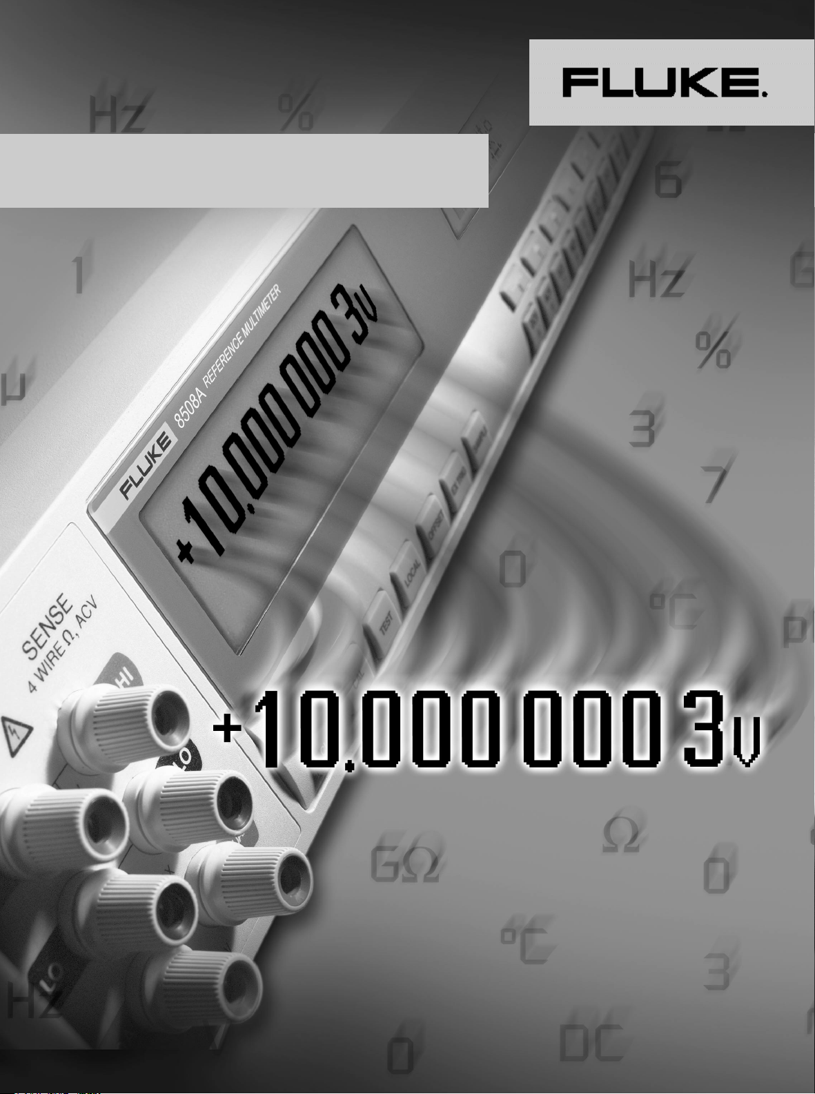
8508A Reference Multimeter
Extended Specifications
Interpreting and applying
the specifications
Introduction
The Fluke 8508A has been designed specifically
for metrologists. Not only does it provide the
performance metrologists need, but it is specified
in a way to allow users to really understand the
uncertainties of the measurements, and easily
make allowance for those uncertainty contributions when performing measurement uncertainty
analyses and compiling uncertainty budgets.
Contemporary metrology practices, including
ISO 17025 based laboratory accreditation
schemes, require uncertainty analysis to be
performed in accordance with the statistically
based techniques described in the ISO Guide to
the Expression of Uncertainty in Measurement
(often referred to as the 'GUM'). For convenience,
the 8508A specifications are quoted at a coverage
factor of k=2, equivalent to a confidence level of
approximately 95 %, as required by these
methods. Specifications are also provided at a
confidence level of 99 %.
Performance specifications for the 8508A
consist of two elements; the first is a contribution
expressed as parts-per-million of the Reading,
and the second contribution is expressed as
parts-per-million of the Range. These must be
evaluated and combined for the relevant reading
and range values applicable to the measurement
being made, ensuring that both elements are
evaluated on the same basis, such as parts per
million of the measured value or in absolute
terms (volts, amps, ohms, etc). The two elements
are combined by adding algebraically. For
example, measuring 10 V on the 20 VDC range
and applying the 365 day ±1 °C specifications:
First, expressing the contributions in terms of
parts-per-million of the measured value.
Second, expressing the contributions in volts:
To realize the full potential of the 8508A performance, accepted metrology practices should
be employed, such as performing a zeroing or
null operation to remove any offsets present in
the measurement setup when making DC measurements. The 8508A specifications assume that
these methods are employed.
Absolute and Relative specifications
The Relative to Calibration Standards specifications describe the performance of the 8508A
itself for the time periods and temperature range
listed, excluding the uncertainty of the standards
used to perform calibration of the 8508A during
manufacture. The Absolute specifications
include the uncertainty of the standards used to
perform calibration of the 8508A at manufacture
and may be used to determine the uncertainty
of measurements made with the 8508A for
periods up to 1 year and over a temperature
range of ±5 °C from calibration. If the user has
their 8508A calibrated with different uncertainties,
the Relative specifications can be combined
with the uncertainties applicable to that
calibration to determine the effective absolute
uncertainty following that calibration.
Applying user’s calibration uncertainties
When the 8508A is calibrated by another
laboratory, the uncertainties of the calibration
standards used may be applied by combining
those uncertainties with the 8508A's Relative to
Standards specifications. The applicable
calibration uncertainties and the 8508A relative
specifications must both be expressed at the
same confidence level, and be combined in an
RSS (Root Sum Square) summation. Accepted
metrology practice mandates that calibration
uncertainties are stated at 95 %. Check the
applicable calibration uncertainties are stated at
95 % and then combine them with the 8508A
95 % Relative specifications. For example, if the
8508A is calibrated at 10 VDC with an
uncertainty of 1.5 ppm at 95 % the absolute
uncertainty at 10 V for a period of 90 days and
±1 °C from calibration is:
The 8508A is designed to provide accuracy
and stability without the need for internal auto
or self calibration routines which may otherwise
compromise the continuity and traceability of
measurement performance history.
2 Fluke Corporation 8508A Extended Specifications
Applying the specifications
Operating and calibration
temperature ranges
As a metrology tool, the 8508A will commonly
be used in a calibration laboratory where the
temperature would be controlled to ±1 °C, and
the 8508A ±1 °C specifications are applicable to
those situations. The majority of electrical
calibration laboratories operate at a nominal
temperature of 23 °C, the temperature at which
the 8508A is calibrated by Fluke during manufacture and service. The 8508A is also capable
of being calibrated at any temperature between
20 °C and 25 °C and the ±1 °C specifications will
apply to operation within ±1 °C of that calibration temperature. In the 8508A specification
tables, the temperature of calibration is referred
to as TCal. Specifications for ±5 °C are provided
for situations where the 8508A is operated in
environments with wider temperature variations
up to ±5 °C. For applications where the knowledge
of the effect of temperature on 8508A performance is important, temperature coefficients are
listed in the 8508A specifications. If the operating
temperature is within the range 15 °C to 30 °C,
the 15 °C to 30 °C temperature coefficient
specifications are applicable; otherwise use the
5 °C to 15 °C/30 °C to 40 °C figures, provided
the temperature lies within that range. The
8508A may be operated at temperatures
between 0 °C and 50 °C, but performance is not
specified outside the range 5 °C to 40 °C.
Applying temperature coefficient
specifications
The 8508A specification tables include
information for the typical operating conditions
of ±1 °C for calibration laboratories with tight
temperature control, and ±5 °C for calibration
laboratories with looser temperature control or
uncontrolled environments within that temperature range. For the majority of applications,
choosing the Absolute specifications for the most
appropriate operating temperature range will be
adequate. However performance at other
temperatures may be determined by including
an allowance for temperature coefficient over
the additional temperature range. Care should
be taken when making this calculation, as an
amount of temperature coefficient is already
included in the 8508A specifications, and those
specifications are themselves based on combining
contributions using techniques similar to those
employed in uncertainty analysis. For example,
consider operating at 33 °C, 10 °C from the 23 °C
calibration temperature. The ±5 °C specifications
already include a contribution for 5 °C of temperature difference, so this amount of temperature
effect must be removed before the effect of the
10 °C difference is added. Consider 10 V on the
20 VDC range: 365 day absolute specification
(95 %) at 33 °C expressed in parts-per-million of
10 V is:
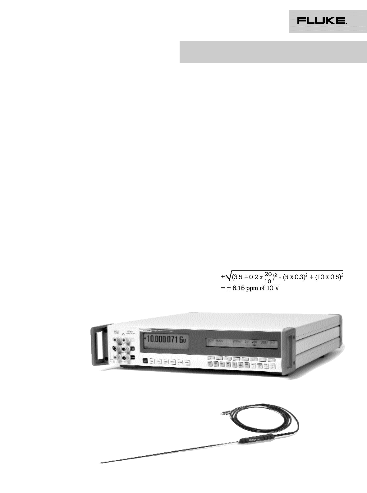
The Fluke 8508A and 8508A-SPRT Standard
Platinum Resistance Thermometer
Fluke Corporation 8508A Extended Specifications 3
Applying the specifications
Ratio measurements
The 8508A Ratio mode will automatically take
measurements of inputs applied to the front and
rear terminals and display the result as a ratio in
the voltage and resistance functions. The
measurements can be made on the same range
or different ranges. When making measurements
on different ranges, the error in each measurement is evaluated by applying the relevant
specification for each range and combining the
two specifications in an RSS summation,
expressing the contributions in parts-per-million
of the measured values. For example, making
measurements of the ratio of 100 mV on the
200 mVDC range and 100 V on the 200 VDC
range, applying the 365 day ±1 °C Absolute
specifications:
Making measurements on the same range
will eliminate range-to-range errors, such as
drift since the time of calibration, and improve
the result. When making measurements on the
same range, these errors will affect both measurements and effectively cancel, leaving short
term noise and linearity as the dominant errors.
The 20 minute Transfer Uncertainty specifications are provided to describe the performance
obtained when making ratio measurements on
the same range. The error in each measurement
is evaluated by applying the relevant 20 minute
Transfer Uncertainty Specification for each value
and combining the two specifications in an RSS
summation, expressing the contributions in
parts-per-million of the measured values. If the
measurements are made within the same range,
but independently (not using the ratio mode)
with an elapsed time greater than 20 minutes
but less than 24 hours between the measurements,
then the 24 hour specifications should be
applied instead.
For example, making measurements of the
ratio of 5 V and 10 V on the 20 VDC range,
applying the 20 minute Transfer Uncertainty
Specifications:
Additional errors
The 8508A specifications are listed for the
maximum resolution in each function, using the
Normal reading mode. For measurements taken
in other resolutions or the Fast read mode
additional error contributions listed in the Read
Rate and Additional Uncertainty table must be
included. These additional contributions must be
added algebraically to the relevant specifications. For example, measuring 10 V on the
20 VDC range at 5 digit resolution in Fast mode
and applying the 365 day ±1 °C Absolute
specifications:
Other additional contributions apply in certain
situations and are also to be added algebraically
to the relevant specifications. These additional
contributions include the DC Accuracy specification to be applied when making DC measurements on the AC Voltage function when DC
coupled, and the High Voltage Adder when
making measurements above 300 V on the AC
function.
4 Fluke Corporation 8508A Extended Specifications
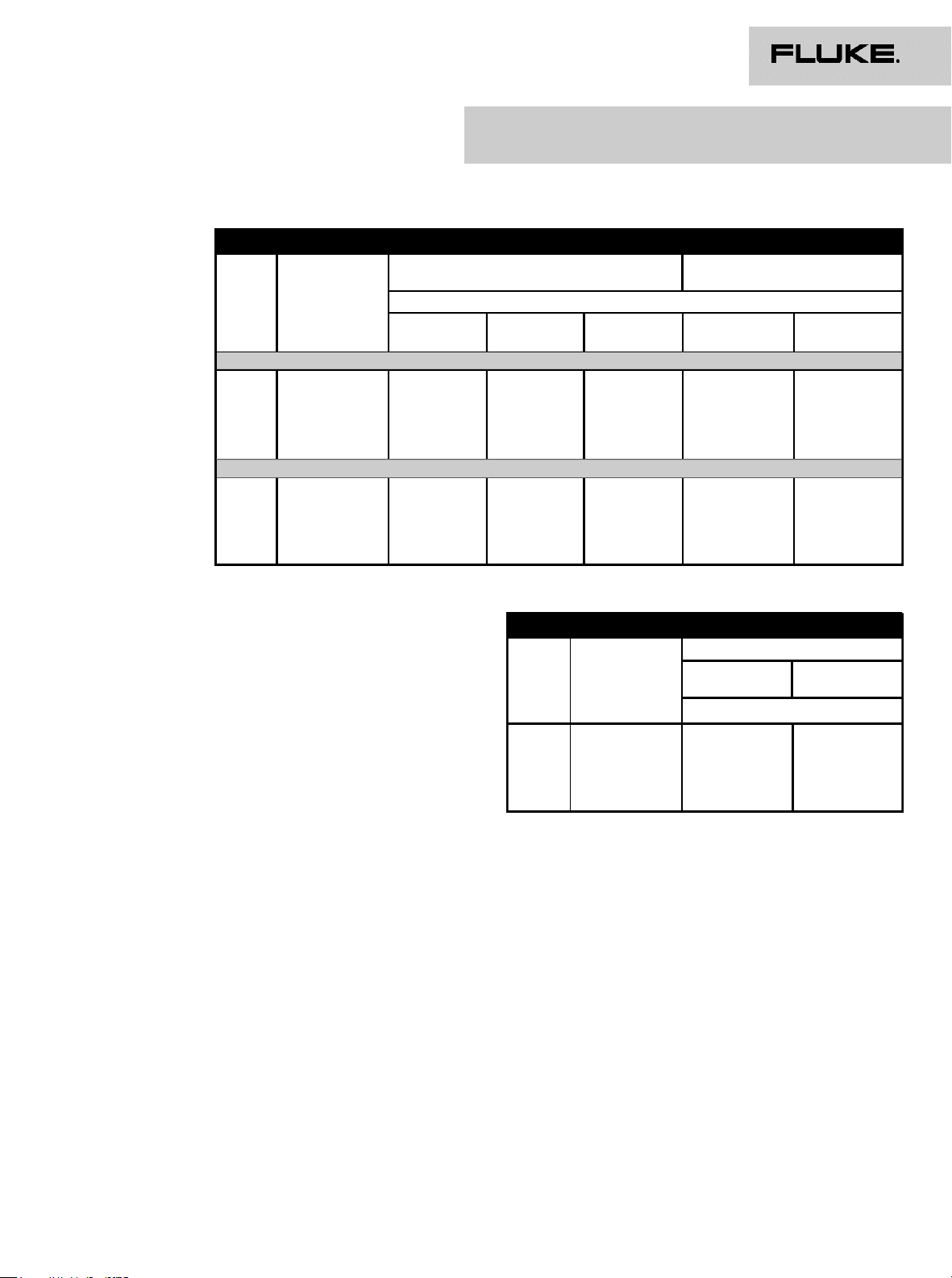
DC Voltage specifications
DC Voltage
Range
[1] [2] [3]
Full Scale Uncertainty Relative to Cal Stds
± (ppm Reading + ppm Range)
24 hour
TCal ±1 °C
90 day
TCal ±1 °C
365 day
TCal ±1 °C
Absolute Uncertainties
[4]
365 day
TCal ±1 °C
365 day
TCal ±5 °C
95 % Confidence Level
200 mV 199.999 999 0.7 + 0.5 1.4 + 0.5 2.7 + 0.5 4.5 + 0.5 5.0 + 0.5
2 V 1.999 999 99 0.5 + 0.2 1.4 + 0.2 2.7 + 0.2 3.0 + 0.2 3.5 + 0.2
20 V 19.999 999 9 0.5 + 0.2 1.4 + 0.2 2.7 + 0.2 3.0 + 0.2 3.5 + 0.2
200 V 199.999 999 1.0 + 0.2 2.6 + 0.2 4.0 + 0.2 4.5 + 0.2 5.5 + 0.2
1000 V 1050.000 00 1.0 + 0.5 2.6 + 0.5 4.0 + 0.5 4.5 + 0.5 5.5 + 0.5
99 % Confidence Level
200 mV 199.999 999 0.8 + 0.6 2.0 + 0.6 3.5 + 0.6 6.0 + 0.6 6.5 + 0.6
2 V 1.999 999 99 0.6+ 0.25 1.8 + 0.25 3.5 + 0.25 4.0 + 0.25 4.5 + 0.25
20 V 19.999 999 9 0.6 + 0.25 1.8 + 0.25 3.5 + 0.25 4.0 + 0.25 4.5 + 0.25
200 V 199.999 999 1.2 + 0.25 3.5 + 0.25 5.2 + 0.25 6.0 + 0.25 7.0 + 0.25
1000 V 1050.000 00 1.2 + 0.6 3.5 + 0.6 5.2 + 0.6 6.0 + 0.6 7.0 + 0.6
DC Voltage
Range
Transfer
Uncertainty
20 mins ±1 °C
± (ppm Reading
+ ppm Range)
(Secondary Specifications)
Temperature Coefficient
15 °C - 30 °C
± ppm Reading/°C
[1] [2] [3]
5 °C - 15 °C
30 °C - 40 °C
200 mV 0.4 + 0.3 0.4 0.6
2 V 0.12 + 0.1 0.3 0.5
20 V 0.12 + 0.1 0.3 0.5
200 V 0.4 + 0.1 0.7 1.0
1000 V 0.4 + 0.3 0.7 1.0
Type Multi-slope, multi-cycle A-D Converter
CMRR (1 kΩ unbalance)
[5]
NMRR
[5]
140 dB at DC and 1 - 60 Hz
Filter Out 60 dB at 50/60 Hz ±0.09 %
Filter In 110 dB at 50/60 Hz ±0.09 %
Protection (All ranges) 1 kV rms
Input Impedance
200 mV to 20 V Ranges >100 GΩ
200 V & 1000 V Ranges 10.1 MΩ ± 1 %
Max Input Current 50 pA
Ratio Accuracy
Range to Range ±(Net Front Input Accuracy + Net Rear Input Accuracy)
Within Range Apply 24 hour or 20 minute Transfer
Uncertainty specifications
Settling Time (to 10 ppm step size)
Filter Out <50 ms
Filter In <1 s
Fluke Corporation 8508A Extended Specifications 5
 Loading...