

Page 1
8500 Series
604-1.
604t
permits
the accuracy
entered into memory
factors are determined bV comparison
cardinal
+1.000000V
range . A non-volatile
factors for
conrplet
604-3.
604-4.
the
rnaintained
the instrumcnt.
604.5.
601-6.
Installation
The interconnect diagranr
listing
604.7.
604-8.
care
high
switch
factor for that
enter an
enter calibration
1.
2.
469684
TNTRODUCTTON
. Installation
c.rtcnded calibration
of the instrument. A calibratiotr
point
for each
dc would
at least one
ely recalibrated.
SPECIFICATIONS
Zero.
DC
cardinal
INSTALLATION
Ref-er to Section
pernrissible
OPERATING
When the Calibration
nrust be
resolution
while in
erroneous
Ensure
durcs
Verify that
are extinguished.
Ohms
points
for
ieast one
at
and Removal
and
exercised
mode .
the higli
function and
factor.
factors.
that the
have been
of' the
Calibration
intervals
with a single
function and range. An input
be the
cardinal
memory allows storage
year
or until
Zero, and
of every range and
year
with no
4 of this ntanual
for installaticln
in
Section
pref'erred
when using
Inadvertently
the
slots.
NOTES
Mernory module
resolution
range
Use the
Zero and Ohms
DC
pertbrmed.
EXT REF and OFFSET
Memory tnodule
while rnaintairring
I'actor is
keystroke. Calibration
to a standard
point
for the 1V dc
at the
of calibration
the instrument is
calibration
factors
function will be
power
applied
under-Module
procedures.
8 contains a table
installed.
is
the instrument
depressing
niode will
from memory
following
in
the STORE
the
erase
procedure to
proce-
Zero
indicators
for
the
cal
and
of
tcr
Calibration
3. Selcct the Cal
4. Select
5. Apply an input
6. Depress
7.
8.
9.
Correction
rms
reading in dc cctupled ac.
604-9.
604-10. The
volatile read/write
and
stants
functions
entered) is broughl out by
was
lbr
storage
function or range
new
frorn
read
troller module.
the desired function and range.
tlie value of the cardinal
seiected
range
+
10.000000V
the
STOI{E switch.
shor"rld be
listed
Repeat
tion and
Depress
uncorrected
equal to the value of tlie input
specil'ication as
steps
range.
the RECALL
reading taken while in the Cal Mem-
ory nrodc. The rcading is displayed
is released.
switch
'fo
renrove Calibration
use tl.re foregoing
ory,
use a short
input
feature
THEORY
Calibration
dc
and
are selected,
within the controller
and stored
(an
terminals
NOTE
Jarlors
automatically
OF
meurory
ohnls
Option
Memory
(CAL
rnode
li-orn
(e.g.,
dc).
4, 5
and 6
open fbr current
instead
entered
OPERATION
Menrory rnodule
zero f-actors. When the dc
the appropriate
is
selected. calibration
fbr
irnntediate
indicator illunrinated).
a
calibration
point
with l0V dc
long
as
for
switch
factors frorl the Cal Mern'
procedure,
of' the
.for
sourcc
the function and
at
selected apply
The reading displayed
the switch is heid in.
each applicable
to display the
exccpt
factors) at the
calibration
V
the
ac
correct any
provides
used to
calibration con-
store
zero factor
ihe instrunrent controlier
tnodule. Likewise.
use within the con-
-04
equal tt.r
1
until the
in step
sourcc.
or
ohms
(if
when a
constants
604-i
thc
funcr-
last
5
non-
one
are
Page 2
8500 Series
604-ll.
one instrument. so
which
The following discrrssion
604-1 .
604-12.
604-13.
This rnodule
not uscd in this
are
RAM Location
R.AM location addresses
Memorv module on
Address
and U14-12. Outputs
the RAMs that data
604-14.
604-15.
are true
and
ory first requires an address
(lD
IC
I
2, 6 clocks
,
Write
Addresses used in both read and write
of 7 codes in
-l
four
low to
5,
0. 3.
6 high.ID
was designed
there are lancl
particuiar
is keyed to the schemalic,
Addresses
the instrurncnt
the
data
I'rom tI23 deterrline the
will be wlitten
Operation
wliich thrce lC
obtain a response. Writing data into ment-
(IC3,4,5
1,2,4,7 loiv) to set thc circuitry
into tl.re write mode. The addrcss is decoded
U14-l
ANDed by
by 1124-1
are
ANDed by U2-11
and to set
Ql)
rnodule is
U24-1
3,
Ul2-2 low
now set into
604-16. The next address
Ul5-6.
one-shot nrultivibrator, Ul-4,
Ul4-13 ANDed by Ul3-10
VA2'WRITij is true
write
the
outputs
RAMs accompanies
ory location
rnode.
U12-l is high
of
the
previously
of the addrcss. VA2
U12-2 high, which sets thc module into
604-17.
604-18.
into the write rnode. Read
resulting in
is low
U2-4 is high sctting the
The desired nremory location nrusi have been clocked
U23
604-1
Read
Operations
The
module stays
VA2
as
(READ).
prior
Ul-3
to the READ address.
9. TROUBLESHOOTING
tll3-3
ANDed
produce
to
the
(low)
RAMs
this
address and
clocked
goes
previously
goes
RAMs
(VAl).
by U l3-4
(WRITE)
write
(1C0.2.6
which
so
(OD).
high
in
operations requirc thc rddress
low
f'or use in more
patterns
are sent
attd sonte
instruttterrt
to tl're Caliblation
data bus.
into Ul3 through
devices
on thc
Figure
ID0-7.
U I
location in
or rcad.
operations
lines
must be
high) and a data
by Ul-5-9,
T'l.re data kcy is decoded
(KEY).
VAI
arrd
the ACK response
through U25 10. The
rnode.
high) is
(VA2).
U2-5,6 are both
so
the RAMs into the
scls
U2-3 is high
Data to bc writte rr
is
storcd
decoded by
V42 triggers a
low and
which disables
irtto the
in the
into U23. At terrnination
clocking
thc read
explained. This f irnc
enabling the RAM outputs.
(Ri$'i
LJ12-l lorv and
the read nrodc.
unless
nrode
ilto the read mode.
than
pcb.
-l
5
high
kcy
KIY
(Ui7,
rnetn-
set
Llll-1
into
fbr
cardinai
rected reading lcsults
recall
cal
604-2 l.
nrine if
value
feature.
constant
T'he threc
the
(lalibration
1. Store
recall the
0.
2. Store cardinal
then recall
3.
Remove
the selected
in the
fairly easy to determine
it is
is stored.
l'ollowing
Me
rnory
zeros fbr
zero
power
all
values.
points
f'or the last uncorrectcd rcading.
for two or nittre
stored constant.
checks
tunctions and rlnges,
for all
that the RAMs have dischargcd
level), then reapply
This checks
Vcc to
of C7 is
whioh
601-22.
Calibration
analysis approach
604-23.
604-21.
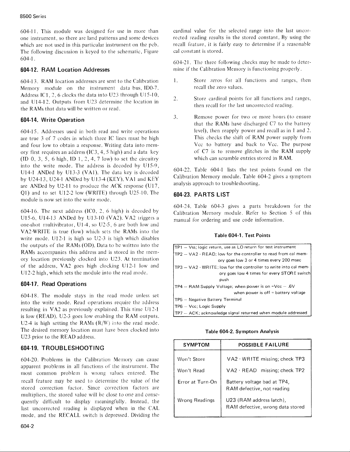
Table 604-1 lists
PARTS
Table 604-3
battery
to rcrnove
scrarnble
can
Memory rnodule. Table 60.1 2
to troubleshooting.
LIST
Calibration Memory
manual
TP1
-fP2
TP3
TP4
TP5
TP6
TP7
for
ordering
logic return,
Vss;
-
VA2. READ;
--
.
VA2
-
-
-
-
SYMPTOM POSSIBLE
WR
RAM Supply
Negative Battery
Vcc; Logic
acknowledge
ACK;
and use
Table 604-1. Test
low
ory
low f
ITE;
ory
push
Voltage; when
Supply
604-2.
Table
power
the
of RAM
shift
back to
and
glitches
entrie s stored in
the test
gives
a
rnodule. Ref'er
code
use
for
goes
goes
Terminal
return
as LO
controller to
the
low 3 or 4 times every 200
controller to write
or the
low 4
power
power
when
signal returned when
Symptom
into the last uncrtr-
range
By using the
if a reasonable
may be rnade
hottrs
C7 to
power
Vcc.
properly.
The
is functioning
functions arrd ranges.
and recall as in 1 and
in the RAM supply
RAM.
points found on the
gives
parts
breakdown
to
Section
information.
Points
for
instrument
test
read f rom cal mem-
into cal mem-
f
or every
times
is
is off = battery
Analysis
STOR
on =Vcc
module addressed
FAILURE
to deter-
(to
ettsure
the battery
l'ront
supply
purpose
a
symptonl
ibr
5
of
msec
E
s
.6V
voltage
then
2.
the
this
604-20.
apparent
rnost
recall feature may be
Problenrs
problems
comrnon
storcd correction
rnultipliers, thc
quenily
difTicult
in the Calibratiori
in all
prclblerr
used
factor.
value wiil irc
stored
to display nrcaninglully.
last uncorrected reading
mode,
604-2
the RECALL switch is depressed.
and
Metttory
functions o1'lhc
jnsirurnent.
is wrong valucs
delernrine
kr
Since correctioti
thc
to one attd consc-
closc
is displayed wlren
causc
can
The
entcred. The
of the
value
tactors
are
Instead. the
in the
Dividing
CAL
thc
Won't
Store
Won't Read
Error
Wrong Readings
Turn-On
at
'WRITE
VA2
'
VA2
READ
Battery voltage bad
RAM defective, not reading
(RAM
U23
RAM defective,
missing;check TP3
missing;check TP2
TP4,
at
address
latch),
wrong
data stored
Page 3
8500 Series
REF
DESIG
OR
ITEM
NO.
BT1
BTI
BTI
C2
C3
C4
CALIBRATION
o
Figure: 60zl-1
Battery
not installed
Battery Lithium
Battery
U9, U2l
Cap, Tr,
Cap,
Cap,
DESCRIPTION
Lithiunr
)
Ni-cad
P/N
408757
0.47 uF
mica,
180
Ta, 0.33 uF
Table
MEMORY
(use
whe
(see
above)
(use
wlien
are
!20%,35Y
pF
5%, 500V
t
+201(,,35V
Calibration
604-3.
ASSEMBLY
n RlO & CR4 are
R20, CR4 and
installed)
Memory
FLUK
STOCK
NO.
408286
448498
4 I 2890
3219
l6l
284786
408690
Assembly
E
MFG
FED
SPLY
CDE
89536
89s36
0600
-56289
1)136
56289
MFG PART.
NO. OR
4082i16
448498
PPS]092
I
r 96D474X0035
l.lAl
DM I5F
lc)6D334X0035
HAI
TYPE
18I
USE
REC
TOT
OTY
OTY
CDE
G
H>
I
I
J
I
I
C5
C6
C]
CRI.
CR2
CR4
Qr
Q3
Q4
Qs
R1
R2, Rr I
R4 thru
R8, Rl2,
Rl
5, Rl6,
R2l, R22,
R25
R24,
Cap, Ta,
Cap, rrrica, 390
Cap, Ta, l0
Diode
Diode,
when
Xstr, Si,
Xstr,
Xstr,
Xstr. Si,
Res,
Res.
Res,
I uF
pF
Hi-speed switching
Hi-speed switching
P/N408757
PNP
NPN
Si,
FET,
N-channel
PNP
dep, 150
car.
dep, 47k
car,
car, dep,
!20%,35V
+
pF
5%,
+
20%,15V
installed)
+5%,,
!57o,
+5%,,
l00k
500V
(use
I
l4W
I
l4W
1l4W
with U9,
U2
9l
l6l
148431
93623
I
20-3323
203313
226290
r68716
370012
t9597
343442
348896
348e20
9
-56
2 89
l96Dl0-sx003-s
I
JAI
l21
56289
36
DMI5F391J
960
I
I 06X
I
I
00r 5KA I
07910
07er0
0471-l
895.16
5.16
89
4
041
8003 I
8003 I
800-l I
I N4448
r N4448
MPS3640
168716
310072
t3
2N3906
CRl5l-.15Pl5lT
cRt5l
('ii:5
-45P4737
-45P
I
I 0l T
3
REF
I
I
I
I
I
I
ll
R9
Rl0
Rl3
Res, mf,
Res, nrf,
Res, rnf,
10k
l%, l/8W
l
l30k + l%, l/8W
+
34k
l%, I
l8W
l 68260
22t618
I 602
26
;i::i
MFFl-81002F
MFF r-8 r 303F
MFF r-83402F
604-3
Page 4
8500
Series
REF
DESIG
OR
ITEM
NO.
Rl4
R20
RNI,
RN2
U]
U2
U3. U4
LI21
U9
u21
U9
Table
604-3.
DESCRIPTIOI\
I k
C-MOS,
4l 2890)
+
1%, I
l8W
+57o.
l/4W
308757
is
installed)
Schottky
qurd.
J-input OR
1024 bit, static RAM
lo24
bit,
static
Res, nrf, 6.04k
Res.
erl. dep.
whcrr P/N
Ull
Res Network
Dgtl, TTL, 1o-pwr
O,a,
f
C. Dgrl. C-VlOS.
S
t!,, Dgtl, C-MOS. dual complimentary
@
pius
lnverter
Sta,Dgtl.
(use
with 408286)
S,a,
Dgtl, c-MoS.
(use
with
Calibration Memory
(use
witlr
LJc).
gares
pair
RANI
Assembly
FLUKE
STOCK
NO.
285 I 89
343425
412908
404186
408393
4080i 3
129860
4081 51
(Concluded)
MFG
FED
SPLY
CDE
91637
8003 l
89s36
01 295
1812s
02135
34649
34649
MFG PART.
NO. OR
MFFl-86041F
cR25
412908
SN74LS
CD4O71 BE
CD4OOTAE
P5101
Ps r
TYPE
i.45P1027
1
23N
L
01L-3
TOT
OTY
1
I
I
2
2
2
REC
OTY
I
I
I
I
I
I
USE
CDE
ut2,u22
ul3
u14
ul5
utl
u24
,
u23
u25
u_(:)
(ttC,
C-MOS. dual
EtC,Dgtl,
C-MOS,
Sta,COS/MOS,
Sta,Dgtl,
Sta,Dgtl,
Sta,Dgtl,
$fC,
StC,Dgtl,
Case half, module
Cover
Decal,
Guard, liont
Guard,
Shield, cover
Socket,
Socket, 1C,2.2
C-N{OS, triple, 3-input AND
C-MOS,
C-MOS,
Dgtl,
C-MOS,
COSiMOS
Moclule
c;ii" memory
rear
cornponent lead
"D"
type. flip-flop
quad,
2-input NAND
4-input NOR
dual
dual4-inpur AND
"D"
hex
flip-flop
hex, inverter/buffer
qua<l
exclusive
Case
prn
gates
gate
OR
gates
gate
gate
340rr7
355198
363820
408807
408199
404509
38 I 848
35s22.2
402990
402914
413484
383356
383364
t97
4t
343285
4s3t26
02135
0213s
0213s
02735
02'735
12040
0273s
02135
89s36
89536
89536
89536
89.536
5
89536
00719
91 506
CD4Ol3AE
IAE
CD4OI
CD4OO2AE
CD4O73B
CD4O82B
MM74CI74N
CD4O49AE
CD4O3OAE
4029e0
402974
4t3484
3 833s6
383364
41r97 5
2-331212-6
322-AG39D
1
2
I
i
I
I
I
I
I
2
I
1
I
I
l
1
2
I
I
I
I
1
2
2
604-4
Page 5

TP3
nrl
\_/
TP+
\_/
O-t:rts_l-€l
Tp5
t
AJ.
ldlplidl#llsl
TT
il
FI
L.J
].AJ.
TTT
o6l
@
@
r.l
tl
lir
lil
l"l
trj
,a\\
{(-}})
\\L-'
14
Page 6

TP6-{R?6F
o
@+
-&-
-1F-
e,Gid0*u
s'rrrrv
rl
ll-
lrl
u
/,4\\
gl
@
E
_E-
Ag [.] l;
i-J
L-l
NH
NOTES:
f- FoR
2.
5.
4.
5.
scHEMArra
FOR P.
a
5. sec
trd
Asiy.
a2O + aR4
a rr-
cs
wru
L?1
A
NI.CAD
}TTIY I9
DrA6bM
M.t.s
DawrN6
wrlL
E^rrlt
BE REpqcED
oNLt
rl |NSTALLID.
i-t
l'"1
L^J
o
3eE
E1op^ -n3q
.
- 3t64)
$E 65&,\-4t6O.
E txtt^llE
ly A JoMru
HITAIE.
A
ldl
ldl
T
.
He
ww
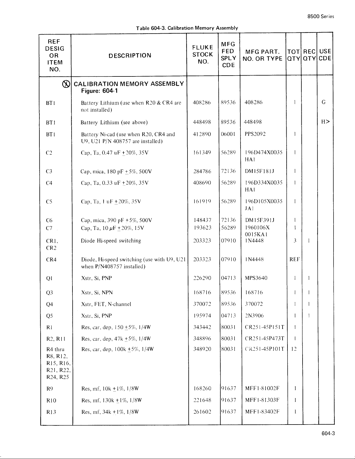
Figure
604-1. Calibration
Memory
Assembly
(85(
Page 7

(+
IDI
tDZ
tD]
ID5
ID6
ID7
Ycc
6
a6
l5
l5
l+
34
t3
ZO
+o
r9
39
t8
l6
r7
11
tz
3l
:l
3?
LA
29
Page 8

8500 Series
1l
,
VAZ
NOTE S
I
6
@
[E-\<af
.
WRI
:
(urrrr-e
ss orHERwlsE
ALL
RES
FOR
REtr. DESTGNATION SEE
FOR PCB
FOR
ASSY.DW6.
LAET REF. DE5. NO's
REF
D€ s. No:s Nor
rzo
cn+
/
iilLL
A JUHP€R WILL BE:
cAurroN
ro AvotD
OCC'TJR
/4W,CC,ALL
TSTOR
DETAIL
SEF ASOOA-+t60.
usso wrEi-{iiiEi?Jr5x-idrEiEtr-iltditriiisuuo.
or{Ly
^RE
BE |NSTALLED
THrS
-
c.uFlt€Nr DRA|N
'DUE
T-O INsTALLATION
spEcrFrED)
REgTSTANCE rN
6500A.
Mt5-3160
SgE
USED: UZ5rO5,CR'f,CJ,RNzrR23rBTl.
:
usE D
u!-
H?rHrgit&.rJ1;ySor
uStNG LrrtruH
l{/|tFr
IN5TALLED
tr€H
W}ITN
s|rorJLD rE
FRof{
OHMs.
t76O
BATTERY.
III-c:AD
USINS
tNSrAL!€',D
BATTER\,Wt|<L
OF
FAULTY
Fr^Hfg.er,.,,
Duttle Tltlr
COITIPc)}I}'GI.
BATTERY.
I
coti,D
604.6
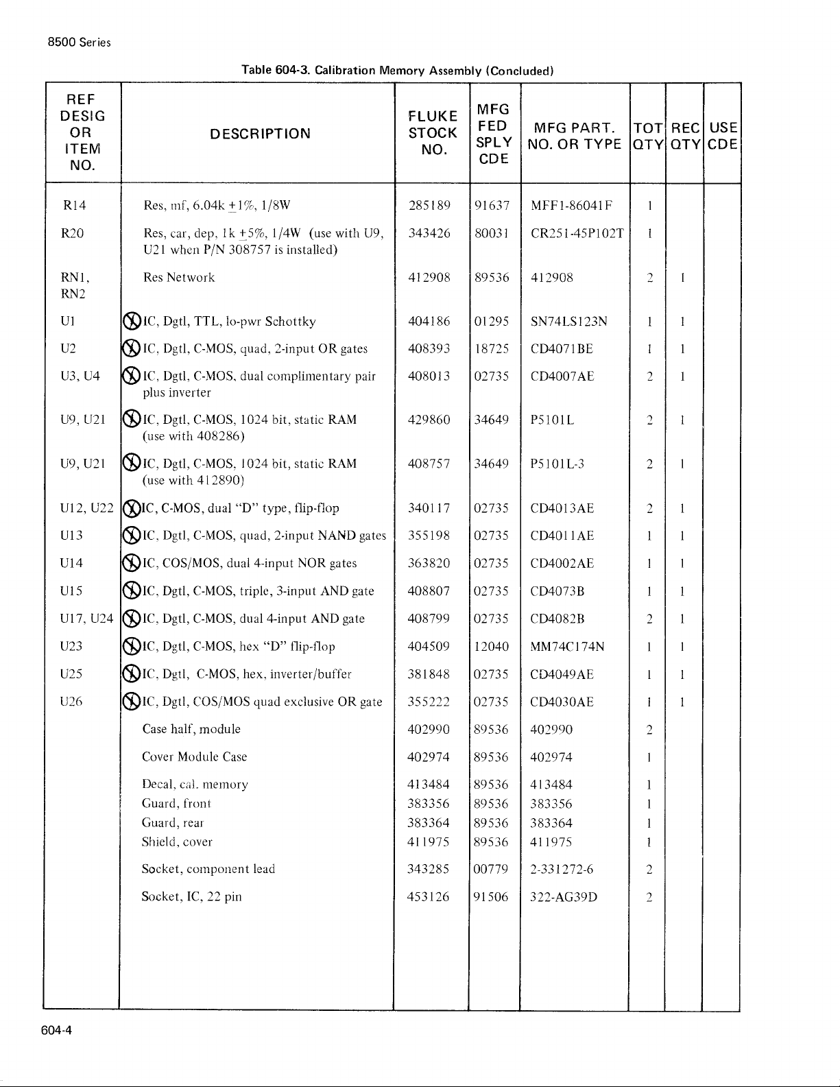
Figure
604-2.
Calibration Memory
+*'
(t/zv)
(8500-1160)
 Loading...