

Page 1
80T-IR/E
Infrared Temperature Probe
Calibration Procedure
®
Introduction
This procedure covers the following topics relating to
the calibration of the Fluke 80T-IR/E Infrared
Temperature Probe, hereafter referred to as the UUT
(Unit Under Test):
• Service Information
• Required Test Equipment
• Calibration Verification
Service
To obtain Service Information in the U.S.A. call 1888-893-5853. Outside the U.S.A., contact your
nearest Fluke Service Center.
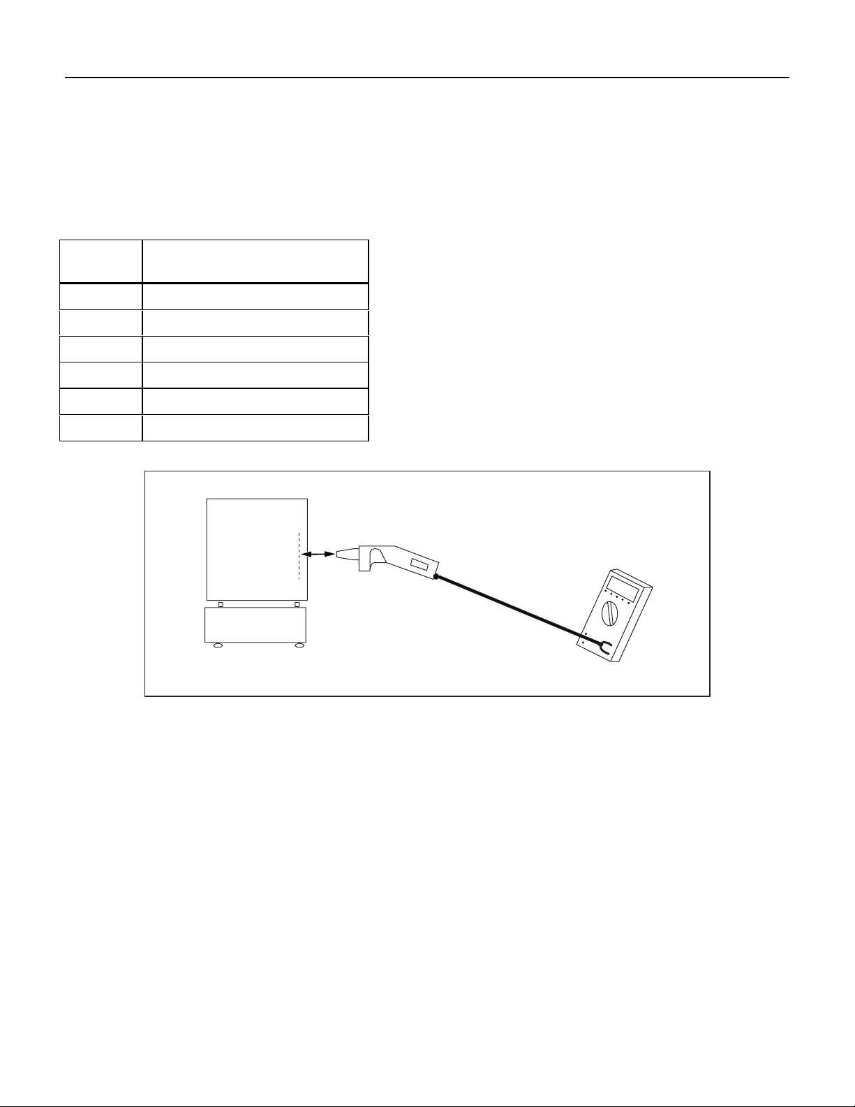
Recommended Equipment
Table 1 lists the equipment required to perform the
calibration verification procedure. Refer to Figure 1
for equipment configuration.
Table 1. Calibration Equipment
Instrument Type Recommended
Model
Blackbody (-20 – 150 °C)
Required Accuracy = +/- 0.75 %
W/Cert. @ 0.95 Emissivity
Blackbody (100-650°C)
Required Accuracy = +/- 0.75 %
W/Cert. @ 0.95 Emissivity
DMM 0.1% Basic Accuracy
1. May substitute less accurate blackbody if using in
conjunction with transfer standard of equivalent
accuracy, i.e.; Raytek PM3-DCI
1
1
Mikron M340
Mikron M305X
Fluke 87
Initial Setup
Each of the measurements listed in the following
procedure assumes that the temperature of the UUT
has stabilized in a test environment with an ambient
temperature of 18 - 28°C and relative humidity of less
than 95%. Accuracy figures are valid for a period of
one year.
1. With the UUT powered on, check that the battery
voltage is at least 7.0 V. Replace the battery if
necessary.
2. Verify that the UUT is in the °F mode.
3. Power up the UUT and allow it to stabilize for
five minutes.
4. Connect the output of the UUT to the VΩ
and
COM input of the DMM.
Calibration Verification
To verify calibration of the 80T-IR/E, complete the
following performance test. If your ins trum ent fa il s to
pass any performance specifications, return it to the
Fluke Factory or Service Center for repair.
1. Adjust the setpoint of the Blackbody to output
each of the temperatures in Table 2 at 0.95
emissivity.
2. Set the DMM to the 3.000 V dc range.
Note
To avoid inaccuracy, only expose the UUT to the heat
source long enough to complete the measurement
(<10 sec). In between measurements move the UUT to
an environment not affected by the heat source.
3. Place the UUT aperature three inches from the
center and perpendicular to both axes of the
Blackbody plate.
4. Record the reading displayed on the DMM.
5. The reading in step 4 must be within 3% or 5° F
(whichever is greater) of the Blackbody output or
transfer standard measurement at 0.95 emissivity
in step 1.
6. Repeat steps 1 through 5 for the remaining
verification points called out in Table 2.
PN 650900
April 2000
©1998 Fluke Corporation. All rights reserved. Printed in U.S.A. 1
Page 2
80T-IR/E
Calibration Procedure
Note
The UUT will shift into sleep mode after 10 minutes.
Reactivate by switching the UUT off and on again.
This completes calibration verification for the
80T-IR/E.
Table 2. Verification Points
Model Blackbody Temperature
at 0.95 Emissivity
M340 77 °F
M340 175 °F
M340 275 °F
M305X 375 °F
M305X 575 °F
M305X 975 °F
Blackbody
3"
Figure 1.
UUT
Test DMM
2
 Loading...