

Page 1

®
724/725/726
Calibrators
Calibration Manual
PN 667581
September 1999 Rev. 2, 2/06
© 1999, 2000, 2006 Fluke Corporation. All rights reserved. Printed in USA
All product names are trademarks of their respective companies.
Page 2

LIMITED WARRANTY AND LIMITATION OF LIABILITY
Each Fluke product is warranted to be free from defects in material and workmanship under normal use and
service. The warranty period is three years and begins on the date of shipment. Parts, product repairs, and
services are warranted for 90 days. This warranty extends only to the original buyer or end-user customer of
a Fluke authorized reseller, and does not apply to fuses, disposable batteries, or to any product which, in
Fluke's opinion, has been misused, altered, neglected, contaminated, or damaged by accident or abnormal
conditions of operation or handling. Fluke warrants that software will operate substantially in accordance with
its functional specifications for 90 days and that it has been properly recorded on non-defective media. Fluke
does not warrant that software will be error free or operate without interruption.
Fluke authorized resellers shall extend this warranty on new and unused products to end-user customers
only but have no authority to extend a greater or different warranty on behalf of Fluke. Warranty support is
available only if product is purchased through a Fluke authorized sales outlet or Buyer has paid the
applicable international price. Fluke reserves the right to invoice Buyer for importation costs of
repair/replacement parts when product purchased in one country is submitted for repair in another country.
Fluke's warranty obligation is limited, at Fluke's option, to refund of the purchase price, free of charge repair,
or replacement of a defective product which is returned to a Fluke authorized service center within the
warranty period.
To obtain warranty service, contact your nearest Fluke authorized service center to obtain return
authorization information, then send the product to that service center, with a description of the difficulty,
postage and insurance prepaid (FOB Destination). Fluke assumes no risk for damage in transit. Following
warranty repair, the product will be returned to Buyer, transportation prepaid (FOB Destination). If Fluke
determines that failure was caused by neglect, misuse, contamination, alteration, accident, or abnormal
condition of operation or handling, including overvoltage failures caused by use outside the product’s
specified rating, or normal wear and tear of mechanical components, Fluke will provide an estimate of repair
costs and obtain authorization before commencing the work. Following repair, the product will be returned to
the Buyer transportation prepaid and the Buyer will be billed for the repair and return transportation charges
(FOB Shipping Point).
THIS WARRANTY IS BUYER'S SOLE AND EXCLUSIVE REMEDY AND IS IN LIEU OF ALL OTHER
WARRANTIES, EXPRESS OR IMPLIED, INCLUDING BUT NOT LIMITED TO ANY IMPLIED WARRANTY
OF MERCHANTABILITY OR FITNESS FOR A PARTICULAR PURPOSE. FLUKE SHALL NOT BE LIABLE
FOR ANY SPECIAL, INDIRECT, INCIDENTAL OR CONSEQUENTIAL DAMAGES OR LOSSES,
INCLUDING LOSS OF DATA, ARISING FROM ANY CAUSE OR THEORY.
Since some countries or states do not allow limitation of the term of an implied warranty, or exclusion or
limitation of incidental or consequential damages, the limitations and exclusions of this warranty may not
apply to every buyer. If any provision of this Warranty is held invalid or unenforceable by a court or other
decision-maker of competent jurisdiction, such holding will not affect the validity or enforceability of any other
provision.
Fluke Corporation
P.O. Box 9090
Everett, WA 98206-9090
U.S.A.
Fluke Europe B.V.
P.O. Box 1186
5602 BD Eindhoven
The Netherlands
11/99
Page 3

Table of Contents
Title Page
Introduction........................................................................................................ 1
Contacting Fluke................................................................................................ 1
Read First – Safety Information......................................................................... 2
International Symbols ........................................................................................ 3
Specifications..................................................................................................... 4
DC Voltage Measurement (724 and 725)...................................................... 4
DC Voltage Measurement and Source (726)................................................. 4
DC Voltage Source (724 and 725) ................................................................ 4
DC mA Measurement and Source (724 and 725)
(Measurement only for 724)....................................................................... 4
DC mA Measurement and Source (726) ....................................................... 5
Ohms Measurement (724 and 725) ............................................................... 5
Ohms Measurement (726) ............................................................................. 5
Ohms Source (724 and 725) .......................................................................... 5
Ohms Source (726)........................................................................................ 6
Frequency Measurement (725)...................................................................... 6
Frequency Measurement (726)...................................................................... 6
Frequency Source (725) ................................................................................ 6
Frequency Source (726) ................................................................................ 7
Millivolt Measurement and Source (724 and 725)........................................ 7
Temperature, Thermocouples (724 and 725)................................................. 7
Temperature, Thermocouples (726) .............................................................. 8
Temperature, RTD Ranges, and Accuracies (724 and 725) .......................... 9
RTD Accuracy (Read and Source) (ITS-90) (726)........................................ 10
Loop Power Supply ....................................................................................... 11
Pressure Measurement (725 and 726) ........................................................... 11
Pulse Read and Pulse Source (726) ............................................................... 11
Pressure Units Availability (725) .................................................................. 11
General Specifications................................................................................... 12
Cleaning the Calibrator...................................................................................... 12
Replacing the Batteries ...................................................................................... 12
Fuses .................................................................................................................. 13
Remote Control Interface (725 and 726) ........................................................... 14
Serial Command List (726)................................................................................ 17
Required Equipment .......................................................................................... 22
Performance Tests.............................................................................................. 24
Preparing for the Performance Tests ............................................................. 24
Upper Display Voltage Measurement Tests .................................................. 25
Lower Display mV/TC Measurement Tests .................................................. 26
Lower Display Voltage Measurement Tests.................................................. 27
i
Page 4

724/725/726
Calibration Manual
Upper Display mA Measurement Tests......................................................... 28
Lower Display mA Measurement Tests (725 and 726)................................. 29
Lower Display Frequency Measurement Test (725 and 726) ....................... 30
Lower Display Frequency Source Test (725 and 726) .................................. 31
Lower Display 4-Wire Resistance Measurement Tests................................. 32
Lower Display 3-Wire RTD Measurement ................................................... 33
Lower Display Thermocouple Measurement Tests....................................... 34
Lower Display Thermocouple Source Test ................................................... 35
Lower Display mA Source Tests (725 and 726) ........................................... 36
Lower Display mV Source Tests................................................................... 37
Lower Display Voltage Source Tests ............................................................ 37
Lower Display Ohms Source Tests ............................................................... 38
Pressure Module Input (725/726).................................................................. 39
Calibration Adjustment...................................................................................... 39
Setup.............................................................................................................. 39
Initiating Communication (724 and 725) ...................................................... 40
Calibration Adjustment Procedures (724 and 725) ....................................... 41
Cal Volts Input .......................................................................................... 41
Cal Volts Output ....................................................................................... 42
Cal mA Input (Fluke 725 Only) ................................................................ 43
Cal mA Output (725 Only) ....................................................................... 44
Cal mV Input............................................................................................. 45
Cal mV Output .......................................................................................... 46
Cal Thermocouples ................................................................................... 47
Cal Ohms Hi Source.................................................................................. 48
Cal Ohms Low Source .............................................................................. 49
Cal RTD Low Range................................................................................. 50
Cal RTD Hi Range .................................................................................... 51
Cal ISO Volts ............................................................................................ 52
Cal ISO mA............................................................................................... 53
Calibration Adjustment Procedures (726) ..................................................... 54
Initiating Communication ......................................................................... 54
Calibrating Isolated mA Input................................................................... 55
Calibrating Isolated Voltage Input ............................................................ 56
Calibrating mA Input ................................................................................ 57
Calibrating mA Output.............................................................................. 58
Calibrating Voltage Input.......................................................................... 59
Calibrating Voltage Output ....................................................................... 60
Calibrating Low Ohms Source.................................................................. 61
Calibrating High Ohms Source ................................................................. 62
Calibrating Ohms Measure........................................................................ 63
Calibrating Thermocouple mV Output ..................................................... 64
Calibrating Thermocouple mV Input ........................................................ 65
Calibrating Thermocouple CJC:................................................................ 66
Replaceable Parts............................................................................................... 67
ii
Page 5

List of Tables
Table Title Page
1. International Symbols ............................................................................................ 3
2. Upper Display Remote Commands (725) .............................................................. 14
3. Lower Display Remote Commands (725).............................................................. 15
4. Remote Commands for Sensor Selection (725) ..................................................... 16
5. Serial Command List-726 ...................................................................................... 17
6. Required Equipment and Software ........................................................................ 23
7. Upper Display Voltage Readings........................................................................... 25
8. Lower Display mV Readings ................................................................................. 26
9. Lower Display Voltage Readings .......................................................................... 27
10. Upper Display mA Readings.................................................................................. 28
11. Lower Display mA Readings ................................................................................. 29
12. Lower Display 4-Wire Resistance Readings.......................................................... 32
13. Type J Thermocouple Readings............................................................................. 34
14. Lower Display Thermocouple Source Readings.................................................... 35
15. Lower Display mA Source Readings ..................................................................... 36
16. Lower Display mV Source Readings ..................................................................... 37
17. Lower Display Voltage Source Readings .............................................................. 37
18. Lower Display Ohms Source Readings.................................................................. 38
19. Replacement Parts.................................................................................................. 67
iii
Page 6

724/725/726
Calibration Manual
iv
Page 7

List of Figures
Figure Title Page
1. Replacing the Batteries and Replaceable Fuses ..................................................... 13
2. Upper Display Voltage Test Connections.............................................................. 25
3. Lower Display mV and Voltage Test Connections................................................ 26
4. Upper Display mA Test Connections..................................................................... 28
5. Lower Display mA Test Connections .................................................................... 29
6. Lower Display Frequency Test Connections ......................................................... 30
7. Lower Display Frequency Source Test Connections ............................................. 31
8. Lower Display 4-Wire Resistance Test Connections............................................. 32
9. Lower Display 3-Wire Resistance Test Connections............................................. 33
10. Lower Display Thermocouple Test Connections................................................... 34
11. Lower Display mA Source Test ............................................................................. 36
12. Lower Display Ohms Source Test Connections.................................................... 38
13. Volts Input Calibration Connections...................................................................... 41
14. Volts Output Calibration Connections ................................................................... 42
15. mA Input Calibration Connections ........................................................................ 43
16. mA Output Calibration Connections...................................................................... 44
17. mV Input Calibration Connections ........................................................................ 45
18. mV Output Calibration Connections...................................................................... 46
19. Thermocouples Calibration Connections ............................................................... 47
20. Ohms Hi Source Calibration Connections ............................................................. 48
21. RTD Low Range Calibration Connections ............................................................ 50
22. ISO Volts Calibration Connections........................................................................ 52
23. ISO mA Calibration Connections .......................................................................... 53
24. Isolated mA Input Calibration Connections........................................................... 55
25. Isolated Voltage Input Calibration Connections .................................................... 56
26. mA Input Calibration Connections ........................................................................ 57
27. mA Output Calibration Connections...................................................................... 58
28. Voltage Input Calibration Connections.................................................................. 59
29. Voltage Output Calibration Connections ............................................................... 60
30. Low Ohms Source Calibration Connections.......................................................... 61
31. High Ohms Source Calibration Connections ......................................................... 62
32. Ohms Measure Calibration Connections................................................................ 63
33. Thermocouple mV Output Calibration Connections.............................................. 64
34. Thermocouple mV Input Calibration Connections ................................................ 65
35. Thermocouple CJC Calibration Connections......................................................... 66
36. Replacement Parts.................................................................................................. 68
v
Page 8

724/725/726
Calibration Manual
vi
Page 9

Introduction
The information provided in this manual is for the use of qualified
personnel only. Do not perform the verification tests or calibration
procedures described in this manual unless you are qualified to do
so.
This Calibration Manual provides the following information for the Fluke 724
Temperature Calibrator and the Fluke 725 and 726 Multifunction Process Calibrators
(also referred to as "the Calibrator" and/or “the UUT”):
• Precautions and safety information
• Equipment required for performance tests and calibration
• Specifications
• Basic maintenance (cleaning, batteries, and fuses)
• Instructions for using the remote control interface
• Performance test procedures
• Calibration procedures
• List of replaceable parts
For complete operating instructions, refer to the appropriate Users Manual (located on
the CD-ROM shipped with the instrument).
The Calibrator contains parts that can be damaged by static
discharge. No procedure in this document requires the case to be
opened. If you do so, follow the standard practices for handling static
sensitive devices.
XWWarning
Caution
Contacting Fluke
To locate an authorized service center, visit us on the World Wide Web at
www.fluke.com or call Fluke using any of the following numbers:
• USA: 1-888-44-FLUKE (1-888-443-5853)
• Canada: 1-800-36-FLUKE (1-800-363-5853)
• Europe: +31 402-675-200
• Japan: +81-3-3434-0181
• Singapore: +65-738-5655
• Anywhere in the world: +1-425-446-5500
1
Page 10

724/725/726
Calibration Manual
Read First – Safety Information
In this calibration manual, a Warning identifies conditions and actions that pose
hazard(s) to the user. A Caution identifies conditions and actions that may damage the
Calibrator or the test instruments.
XWWarnings
To avoid possible electric shock or personal injury:
•
DO NOT use the Calibrator if it looks damaged.
•
Follow all safety procedures for the test and calibration equipment you
use.
•
Examine the Calibrator before use. Look for cracks in the case, missing plastic,
or damaged insulation around the connectors.
• Inspect the test leads for damaged insulation or exposed metal. Check for
test lead continuity. Replace damaged test leads as necessary.
• Do not use the Calibrator if it operates abnormally. Protection may be
impaired. When in doubt, have the instrument serviced.
• Do not apply more than the rated voltage, as marked on the Calibrator,
between terminals or between any terminal and earth ground.
• Never touch the probes to a voltage source when the test leads are plugged
into the current terminals.
• Select the proper function and range for each measurement.
• Disconnect the test leads before changing to another measure or source
function.
• When using probes, keep fingers behind the finger guards on the probes.
• Use caution when working above 30 V ac rms, 42 V ac peak, or 60 V dc.
Such voltages pose a shock hazard.
• Connect the common lead (COM) before connecting the live test lead. When
disconnecting test leads, disconnect the live test lead first.
• Always place the 5520A calibrator in Standby (STBY) mode between tests
and before handling the test connections or cables.
• Remove test leads from the Calibrator before opening the battery door.
• Do not operate the Calibrator around explosive gas, vapor, or dust.
• During normal operation, only use four properly installed AA batteries to
power the Calibrator.
• Make sure the battery door is closed and latched before you operate the
Calibrator.
2
• During calibration, use only specified calibration equipment listed in
Table 6.
(Continued on the next page)
Page 11
Calibrators
International Symbols
XWWarnings (cont)
• When servicing the Calibrator, use only specified replacement parts.
• To avoid false readings, which can lead to possible electric shock or personal
injury, replace the batteries as soon as the low battery indicator (
Caution
To avoid possible damage to the Calibrator or to the test instruments:
• Disconnect the power and discharge all high voltage capacitors before
testing resistance, diodes, or continuity.
• Use the proper jacks, function, and range for each measurement or
sourcing application.
B) appears.
International Symbols
International symbols used on the Calibrator and in this manual are explained in Table 1.
Table 1. International Symbols
Symbol Meaning Symbol Meaning
B
F
D
f
W
X
~
Alternating current
Direct current
Alternating or direct current
Pressure
Refer to the manual.
Important information.
Take appropriate precautions.
Hazardous voltage may be present.
Do not dispose of this product as unsorted municipal waste. Contact Fluke or a qualified
recycler for disposal.
J
O
P
B
)
T
Earth ground
ON/OFF
Conforms to European Union directives
Battery
Conforms to relevant Canadian
Standards Association directives
Double insulated
3
Page 12
724/725/726
Calibration Manual
Specifications
DC Voltage Measurement (724 and 725)
30 V (upper display) 0.001 V 0.02 % + 2
20 V (lower display) 0.001 V 0.02 % + 2
90 mV (lower display) 0.01 mV 0.02 % + 2
Temperature coefficient -10 °C to +18 °C, 28 °C to 55 °C: ±0.005 % of range per °C
DC Voltage Measurement and Source (726)
Performance and accuracy are specified for one year after calibration, at operating
temperatures of +18 °C to +28 °C (64 °F to 82 °F), in relative humidity to 90 %, after a
5 minute warm up period.
Note
A “count” is the amount by which the least significant digit can vary.
Range Resolution Accuracy (% of Reading + Counts)
Range Minimum Maximum
30 V (upper display) 0.000 V 30.000 V 0.010 % + 2 mV
20 V (lower display) 0.000 V 20.000 V 0.010 % + 2 mV
20 V (Source) 0.000 V 20.000 V 0.010 % + 2 mV
100 mV (Source) 0.000 V 100.000 mV 0.010 % + 10 µV
90 mV (Read) 0.000 V 90.000 mV 0.010 % + 10 µV
Maximum current output in voltage ranges is 1 mA with an output impedance of ≤ 1 Ω
Accuracy,
(% of Reading + Floor)
DC Voltage Source (724 and 725)
Range Resolution Accuracy (% of Reading + Counts)
100 mV 0.01 mV 0.02 % + 2
10 V 0.001 V 0.02 % + 2
Temperature coefficient -10 °C to +18 °C, 28 °C to 55 °C: ±0.005 % of range per °C
Maximum load: 1 mA
DC mA Measurement and Source (724 and 725) (Measurement only for 724)
Range Resolution Accuracy ( % of Reading + Counts)
4
24 mA 0.001 mA 0.02 % + 2
Temperature coefficient -10 °C to +18 °C, +28 °C to 55 °C: ±0.005 % of range per °C
Drive capability: 1000 Ω at 20 mA
Page 13
Calibrators
Specifications
DC mA Measurement and Source (726)
Accuracy,
Range Minimum Maximum
mA Read (Upper Display) 0.000 24.000 0.010 % + 2 µA
mA Read (Lower Display) 0.000 24.000 0.010 % + 2 µA
mA Source 0.000 24.000 0.010 % + 2 µA
Maximum load on, mA source is 1 kΩ. With the HART resistor on, maximum load is 750 Ω.
Voltage input range on simulate mode is 5 to 30 V
(% of Reading +
Floor)
Ohms Measurement (724 and 725)
Ohms Range Accuracy, 4-Wire Accuracy*, 2-Wire, or 3-Wire
0 Ω to 400 Ω** ±0.1 Ω ±0.15 Ω
400 Ω to 1.5 kΩ ±0.5 Ω ±1.0 Ω
1.5 Ω to 3.2 kΩ ±1 Ω ±1.5 Ω
Excitation Current: 0.2 mA
Maximum input voltage: 30 V
Temperature coefficient -10 °C to +18 °C, +28 °C to 55 °C: ±0.005 % of range per °C
* 2-wire: Does not include lead resistance.
** For Firmware V1.7 or lower, the lowest range is 15 Ω to 400 Ω.
3-wire: Assumes matched leads with a total resistance not exceeding 100 Ω.
Ohms Measurement (726)
Ohms Range Minimum Maximum
Ohms Read (low) 0.00 400.00 0.015 % + 0.05 Ω
Ohms Read (high) 400.0 4000.0 0.015 % + 0.5 Ω
Accuracy
(% of Reading + Floor)
Ohms Source (724 and 725)
Ohms Range Excitation Current from Measurement Device
15 Ω to 400 Ω 0.15 mA to 0.5 mA ±0.15 Ω
15 Ω to 400 Ω 0.5 mA to 2 mA ±0.1 Ω
400 Ω to 1.5 kΩ 0.05 mA to 0.8 mA ±0.5 Ω
1.5 Ω to 3.2 kΩ 0.05 mA to 0.4 mA ±1 Ω
Accuracy
Temperature coefficient -10 °C to +18 °C, 28 °C to 55 °C: ±0.005 % of resistance range per °C
Resolution
15 to 400 Ω 0.1 Ω
400 to 3.2 kΩ 1 Ω
5
Page 14
724/725/726
Calibration Manual
Ohms Source (726)
Ohms Range Minimum Maximum
Ohms Source (low)
Ohms Source (high)
Unit is compatible with smart transmitters and PLCs.
Frequency response is ≤ 5 mS
5.0 400.0 0.1 to 0.5 mA
5.0 400.0 0.5 to 3 mA
400 1500 0.05 to 0.8 mA
1500 4000 0.05 to 0.4 mA
Excitation Current from
Measurement Device
(% of Reading +
0.015 % + 0.1 Ω
0.015 % + 0.05 Ω
0.015 % + 0.5 Ω
0.015 % + 0.5 Ω
Frequency Measurement (725)
Range Resolution Accuracy
2.0 to 1000.0 CPM 0.1 CPM ± (0.05 % + 1 count)
1 to 1000 Hz 0.1 Hz ± (0.05 % + 1 count)
1.0 to 10.0 kHz 0.01 kHz ± (0.05 % + 1 count)
Sensitivity: 1 V peak-to-peak minimum
Waveform: Squarewave
Frequency Measurement (726)
Accuracy
Floor)
Accuracy
Range Minimum Maximum
CPM Read 2.0 1000.0 0.05 % + 0.1 CPM
Hz Read 1.0 1000.0 0.05 % + 0.1 Hz
KHz Read 1.00 15.00 0.05 % + 0.01 KHz
(% of Reading +
Floor)
Frequency Source (725)
Range Resolution Accuracy (% of output frequency)
2.0 to 1000.0 CPM 0.1 CPM ± 0.05 %
1 to 1100 Hz 1 Hz ± 0.05 %
1.0 to 10.0 kHz 0.1 kHz ± 0.25 %
Waveform: 5 V p-p squarewave, -0.1 V offset
6
Page 15
Calibrators
Specifications
Frequency Source (726)
Range Minimum Maximum Accuracy
CPM Source 2.0 1000 0.05 %
Hz Source 1.0 1000.0 0.05 %
KHz Source
1.0 10.00 0.25 %
10.00 15.00 0.50 %
Millivolt Measurement and Source (724 and 725)
Range* Resolution Accuracy
-10 mV to +75 mV 0.01 mV ±(0.025 % + 1 count)
Maximum input voltage: 30 V
Temperature coefficient -10 °C to +18 °C, 28 °C to 55 °C: ±0.005 % of range per °C
*Select this function by pressing T. The signal is available at the thermocouple miniplug connector.
Temperature, Thermocouples (724 and 725)
Type Range (°C) Measure and Source Accuracies (°C)
J
K
T
E
R
S
B
L
U
N*
Resolution:
J, K, T, E, L, N, U: 0.1 °C, 0.1 °F
B, R, S: 1 °C, 1 °F
* For Firmware V1.7 or lower, the type N TC has 400 °C as the upper limit.
-200 to 0
0 to 1200
-200 to 0
0 to 1370
-200 to 0
0 to 400
-200 to 0
0 to 950
-20 to 0
0 to 500
500 to 1750
-20 to 0
0 to 500
500 to 1750
600 to 800
800 to 1000
1000 to 1800
-200 to 0
0 to 900
-200 to 0
0 to 400
-200 to 0
0 to 1300
1.0
0.7
1.2
0.8
1.2
0.8
0.9
0.7
2.5
1.8
1.4
2.5
1.8
1.5
2.2
1.8
1.4
0.85
0.7
1.1
0.75
1.5
0.9
7
Page 16
724/725/726
Calibration Manual
Temperature, Thermocouples (726)
Type Minimum Maximum
-210 0.0 0.6 0.4
J
K
T
E
R
S
B
C
L
U
N
XK -200 800 0.4 0.2
BP
Thermocouple in mV read -10 mV to 75 mV
Thermocouple in mV source -10 mV to 75 mV
Maximum current output in voltage ranges is 1 mA with an output impedance of ≤ 1 Ω
CJC error outside of 23 ± 5 °C is 0.05 °C / °C
0.0 800 0.4 0.2
800 1200 0.5 0.3
-200 0.0 0.8 0.6
0.0 1000 0.5 0.3
1000 1372 0.7 0.5
-250 0.0 0.8 0.6
0.0 400 0.4 0.2
-250 -100 0.8 0.6
-100 1000 0.4 0.4
-20 0.0 2.0 1.8
0.0 1767 1.4 1.2
-20 0.0 2.0 1.8
0.0 1767 1.4 1.2
600 800 1.4 1.2
800 1000 1.5 1.3
1000 1820 1.7 1.5
0.0 1000 0.8 0.6
1000 2316 2.5 2.3
-200 0.0 0.45 0.25
0.0 900 0.4 0.2
-200 0.0 0.7 0.5
0.0 600 0.45 0.25
-200 0.0 1.0 0.8
0.0 1300 0.6 0.4
0.0 800 1.1 0.9
800 2500 2.3 2.1
Range Accuracy
CJC ON
Accuracy
CJC OFF
Accuracy
0.015 % + 10 µV
(% of Reading +
Floor)
0.015 % + 10 µV
(% of Reading +
Floor)
8
Page 17
Calibrators
Specifications
Temperature, RTD Ranges, and Accuracies (724 and 725)
Type
Ni120 -80 to 260 0.2 0.3 0.2
Pt100-385 - 200 to 800 0.33 0.5 0.33
Pt100-392 -200 to 630 0.3 0.5 0.3
Pt100-JIS -200 to 630 0.3 0.5 0.3
Pt200-385
Pt500-385
Pt1000-385
Resolution: 0.1 °C, 0.1 °F
Allowable excitation current (source): Ni120, Pt100-385, Pt100-392, Pt100-JIS,
Pt200-385: .05 to .80 mA,Pt500-385: 0.05 to 0.80 mA; Pt1000-385: 0.05 to 0.40 mA
RTD Source: Addresses pulsed transmitters and PLCs with pulses as short as 5 ms. SN < 7624001 may
need modification for pulses less than 15 ms.
*2-wire: Does not include lead resistance.
3-wire: Assumes matched leads with a total resistance not exceeding 100 Ω.
Range (°C)
-200 to 250
250 to 630
-200 to 500
500 to 630
-200 to 100
100 to 630
Measure
4-wire (°C)
0.2
0.8
0.3
0.4
0.2
0.2
Accuracy
Measure*
2- and 3-wire (°C)
0.3
1.6
0.6
0.9
0.4
0.5
Source (°C)
0.2
0.8
0.3
0.4
0.2
0.2
9
Page 18
724/725/726
Calibration Manual
RTD Accuracy (Read and Source) (ITS-90) (726)
Ni120 (672) -80.00 260.00 0.15
Range Minimum Maximum Accuracy
-200.00 100.00 0.15
Pt100 (385)
Pt100 (3926)
Pt100 (3916)
Pt200 (385)
Pt500 (385)
100.00 300.00 0.25
300.00 600.00 0.35
600.00 800.00 0.45
-200.00 100.00 0.15
100.00 300.00 0.25
300.00 630.00 0.35
-200.00 100.00 0.15
100.00 300.00 0.25
300.00 630.00 0.35
-200.00 100.00 0.75
100.00 300.00 0.85
300.00 630.00 0.95
-200.00 100.00 0.35
100.00 300.00 0.45
300.00 630.00 0.55
-200.00 100.00 0.15
Pt1000 (385)
CU10 -10.00 250.00 1.8
Notes: Read Accuracy is based on 4-wire input. For 3-wire input, add ± 0.05 Ω assuming all three RTD
leads are matched.
Source Accuracy is based on 0.5 to 3.0 mA excitation current (0.1 mA for pt1000 range)
Resolution: 0.1 °C, 0.1 °F
Allowable excitation current (source): Ni120, Pt100-385, Pt100-392, Pt100-JIS,
Pt200-385: .05 to .80 mA,Pt500-385: 0.05 to 0.80 mA; Pt1000-385: 0.05 to 0.40 mA
RTD Source: Addresses pulsed transmitters and PLCs with pulses as short as 5 ms. SN < 7624001 may
need modification for pulses less than 15 ms.
100.00 300.00 0.25
300.00 630.00 0.35
10
Page 19
Calibrators
Specifications
Loop Power Supply
Voltage: 24 V
Maximum current: 22 mA
Short circuit protected
Pressure Measurement (725 and 726)
Range Resolution Accuracy Units Mode (726 Only)
Determined by
pressure module
5 digits
Determined by
pressure module
psi, inH
inH
cmH
cmH
mbar, kg/cm
inHg
O@4 °C,
2
O@20 °C, kPa,
2
O@4 °C,
2
O@20 °C, bar,
2
, mmHg,
2
Pushing A for 3
seconds stores
present pressure
value as an offset and
subtracts it from the
displayed value.
Pulse Read and Pulse Source (726)
Pulse Min Max Accuracy Frequency
Source 10,000
Read
1
100,000
1 Count 2 CPM to 10 kHz
Pressure Units Availability (725)
Unit Availability
psi Available on all pressure ranges
inH2O All ranges through 3000 psi
cmH2O All ranges through 1000 psi
bar 15 psi and above
mbar All ranges through 1000 psi
kPa Available on all pressure ranges
inHg Available on all pressure ranges
mmHg All ranges through 1000 psi
kg/cm2 15 psi and above
11
Page 20
724/725/726
Calibration Manual
General Specifications
Operating temperature
724 and 725
726
Storage temperature - 20 °C to 70 °C
Stability ± 0.005 % of range/°C outside of 23 ± 5 °C
Operating altitude 3000 meters above mean sea level
Relative Humidity (% RH operating without
condensation)
Vibration Random, 2 g, 5 Hz to 500 Hz
Safety
724 and 725
726
Power requirements 4 AA alkaline batteries
Protection Class Pollution Degree II
-10 °C to 55 °C
-10 °C to 50 °C
90 % (10 to 30 °C)
75 % (30 to 40 °C)
45 % (40 to 50 °C)
35 % (50 to 55 °C)
uncontrolled < 10 °C
EN 61010-1:1993, ANSI/ISA S82.01-1994; CAN/CSA
C22.2 No 1010.1:1992
EN50082-1:1992 and EN55022: 1994 Class B Criteria
A or B CSA C22.2 No 1010.1:1992
Size 96 x 200 x 47 mm (3.75 x 7.9 x 1.86 in)
Weight 650 gm (1 lb, 7 oz)
Cleaning the Calibrator
XWWarning
To avoid electric shock or damage to the Calibrator, never allow water
inside the Calibrator’s case.
If the Calibrator requires cleaning, wipe it down with a cloth that is lightly dampened
with water or a mild detergent.
Do not use aromatic hydrocarbons, chlorinated solvents, or methanol-based fluids when
cleaning the Calibrator. To avoid damaging the case, never apply solvents to the
Calibrator.
Replacing the Batteries
XWWarning
To avoid electric shock, remove the test leads from the Calibrator
before opening the battery door. Close and latch the battery door
before using the Calibrator.
To avoid false readings, which can lead to possible electric shock or
personal injury, replace the batteries as soon as the low battery
indicator (
B) appears.
12
When replacing the batteries, always use four new AA batteries. Never
mix new and used batteries in the Calibrator.
Page 21
Calibrators
Fuses
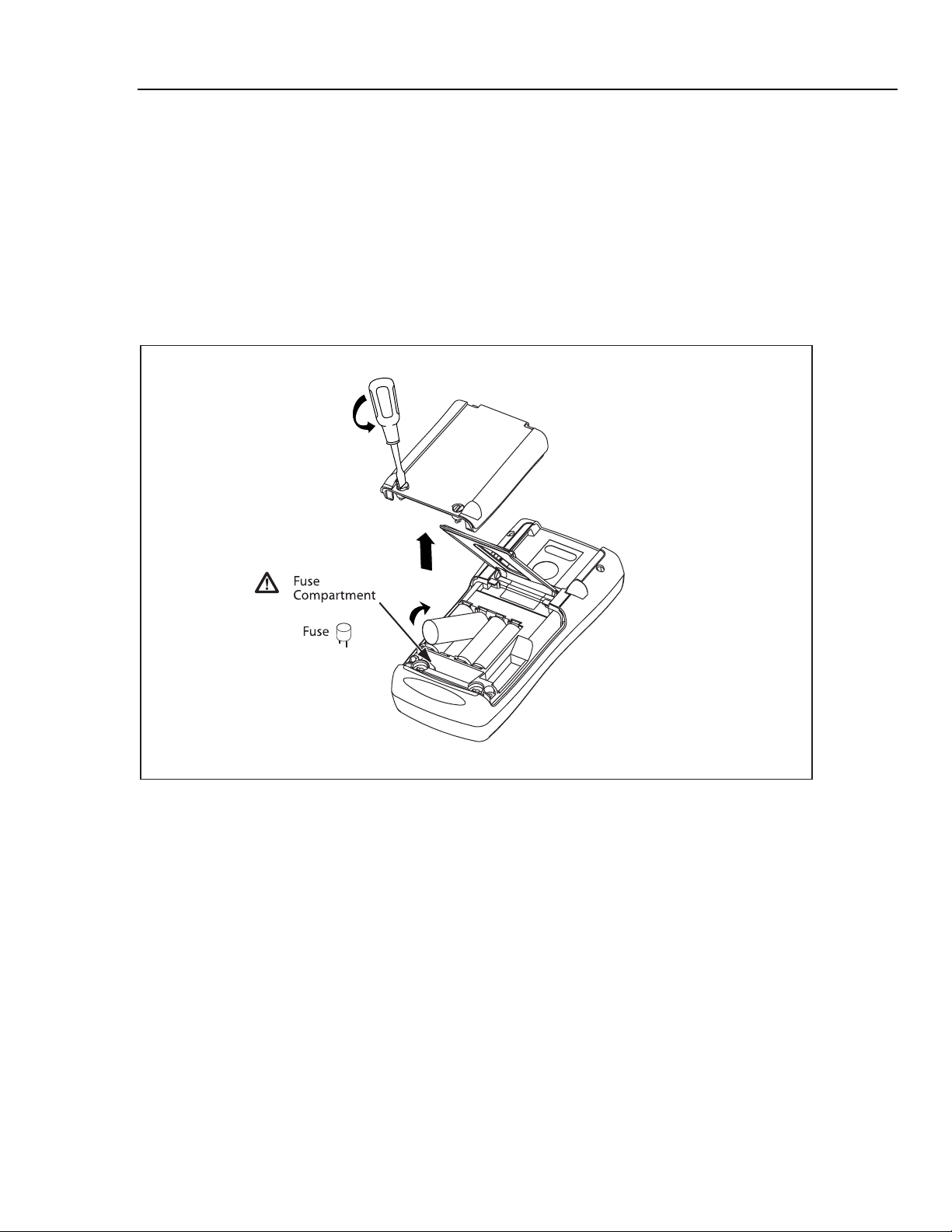
Four AA alkaline batteries (ANSI/NEDA 15A or IEC LR6) are used to power the
Calibrator. To replace the batteries, refer to Figure 1 and do the following:
1. Turn the Calibrator off, remove the test leads from the terminals, and hold the
Calibrator face down.
2. Using a flat-blade screwdriver, turn the battery door screws 1/4-turn
counterclockwise and remove the battery door.
3. Remove the batteries, then install new batteries. Be sure to follow the polarity
markings shown in the battery compartment.
4. Replace the battery door and secure it by turning the screws 1/4-turn clockwise.
Fuses
Over time, the input protection has been modified to increase reliability. There will either
be self-resetting fuses, or replaceable fuses in sockets. The self-resetting fuses open when
heated by a current overload, and close when they cool down. When an input’s fuse is
open, the input’s functions will not work.
Figure 1. Replacing the Batteries and Replaceable Fuses
XWWarning
To avoid electrical shock:
• Remove the test leads from the calibrator before opening the
battery door. Close and latch the battery door before using the
calibrator.
• Use only the specified replacement fuses listed under
“Replaceable Parts”.
• Do not allow water into the case.
13
aal01f.eps
Page 22

724/725/726
Calibration Manual
The time required for a self-resetting fuse to reset depends on the magnitude of the
overload. If a self-resetting fuse does not reset, return the Calibrator to an authorized
service center for repair.
If a replaceable fuse has been damaged, it needs to be replaced. The fuses can be
removed and checked for resistance. A value of < 10 Ω is good.
The calibrator comes equiped with three 0.2 A 250 V socketed fuses.
• Problems while measuring with the right jacks indicate that F3 may have opened.
• Problems while measuring
or sourcing with the center jacks or the TC jacks
indicate that F2 may have opened.
• If you can’t measure or source current with the left jacks, F4 may have opened.
To access the fuses, refer to instructions under “Replacing the Batteries”. The fuse
compartment is located below the battery compartment. Use needle-nosed pliers to
remove them and test them with a multimeter. Replace the fuse with the proper
replacement fuse and follow the directions for reassembling the Calibrator. Refer to
Figure 1.
Remote Control Interface (725 and 726)
The Calibrator’s serial interface and remote control commands let you use a PC to
remotely select Calibrator functions and read the Calibrator’s display. This remote
interface is especially useful if you want to write your own calibration software.
The 726 remote control interface is always active.
To activate the 725 remote control interface, proceed as follows:
1. Turn off the UUT; then use the Fluke 700SC serial interface cable to connect the
UUT to a serial port on the PC.
2. Start the terminal communication software on the PC. Create a new connection with
the following properties:
• Bits per second: 9600
14
• Data bits: 8
• Parity: None
• Stop bits: 1
• Flow control: None
• Local echo on
3. Hold down the Calibrator’s M button while turning the Calibrator on.
4. Use the commands given in Tables 2 through 4 to remotely control the Calibrator.
Table 2. Upper Display Remote Commands (725)
Remote Command Description
i mA measurement
L mA Loop Power
E Voltage measurement
B Single broadcast of the most recent upper display value and units
( Single broadcast of most recent upper display value without header or units
Page 23

Calibrators
Table 3. Lower Display Remote Commands (725)
Remote Command Description
A mA measurement
a mA source
I mA 2W Sim
V Voltage measurement
v Voltage source
M mV measurement
m mV source
K kHz measurement
k kHz source
H Hz measurement
h Hz source
P CPM measurement
p CPM source
O Ohms measurement (default 2W)
o Select Ohms source
W 2-wire measurement (Ohms and RTDs)
X 3-wire measurement (Ohms and RTDs)
Y 4-wire measurement (Ohms and RTDs)
T Thermocouple measurement (default Type J). Use “S” command to select a
sensor type.
t Thermocouple source (default Type J). Use “S” command to select a sensor type
C Selects Centigrade ( T/C-RTD)
F Selects Fahrenheit ( T/C-RTD)
R RTD measurement mode (default Pt100 385). Use “S” command to select a
sensor type
r RTD measurement mode (default Pt100 385). Use “S” command to select sensor
type.
u Increment display source value
d Decrement display source value
< The < arrow key PC keyboard selects left arrow on 725
> The > arrow key PC keyboard selects right arrow on 725
0-9 Enter a source value using ASCII characters 0,1,2,...9,-,.terminated by <CR>
(carriage return)
-,. The 725 can receive a maximum of 10 characters prior to the carriage return.
<CR>
b Single Broadcast of most recent lower display value and units
) Single broadcast of most recent lower display value without header or units.
Remote Control Interface (725 and 726)
15
Page 24
724/725/726
Calibration Manual
Serial Input No. Thermocouple Type RTD Type
2 K Pt100 (385)
3 T Pt100 (3916)
4 E Pt200 (385)
5 R Pt500 (385)
6 S Pt1000 (385)
7 B Ni120
8 L -
9 U -
A N -
Table 4. Remote Commands for Sensor Selection (725)
Selection Entry
S 1 J Pt100 (3926)
B mV -
16
Page 25

Calibrators
Serial Command List (726)
Serial Command List (726)
Table 5 lists the serial commands for the 726 Calibrator. Refer to “Remote Control
Interface (725 and 726)” for activation steps.
Table 5. Serial Command List-726
Command Response/Actions
*IDN? Returns the ID string
“FLUKE,726,0,{sw_rev}” where
sw_revision is the firmware
revision
FUNC? Returns {Upper},{Lower}
{Upper} responses
(Channel 1)
DCI, DCI_LOOP, DCV,
DCI_ERROR,
DCI_ERROR_LOOP
{Lower} responses
DCI, DCMV, DCV, DCI_SIM, TC,
RTD, FREQUENCY,
PULSE_TRAIN
VAL? Returns the measured value with
base units for the upper and lower
display
{upper_val},{upper_units},{lower_
val},{lower _units},
upper_units: V, A, PERCENT
lower _units: V, CEL, FAR, A,
OHM, CPM, HZ, COUNT
Command
Arguments
Verify model
Answers with
Comment Ch 1 Ch 2
number and
firmware
revision
the configured
function for the
upper and
lower display
X X
X X
X X
UPPER_MEAS 1 argument, valid
settings: DCI,
DCI_LOOP, DCV,
DCI_ERROR,
DCI_ERROR_LOOP
17
Set upper
channel
measure mode X
Page 26

724/725/726
Calibration Manual
Table 5. Serial Command List-726 (cont.)
Command Response/Actions
Command
Arguments
OUT Arguments:
{value} {units}
Multipliers:
u for micro, m for
milli, and k for kilo
are accepted.
Units:
-V used for mV and
Volts, the V_range
command can be
used to switch
ranges
-CEL used for RTD,
TC AND TC mV
-FAR used for RTD
and TC
-A used for mA (see
SIM for mA SIM)
-OHM used for RTD
ohms, RTD_TYPE
must be set to ohms
-CPM used for
frequency
-HZ used for HZ and
KHZ frequency (unit
will auto range)
-COUNT used for
pulse
Comment Ch 1 Ch 2
Configures
the output
source
function. If the
{value} and
{units} are
valid, this
command will
change
modes if
necessary
and set the
output value
to {value} and
{units} in that
mode.
X
18
OUT? Returns the output (source)
value with units or none.
FREQ_UNIT 1 argument: CPM,
Verify the
output
function and
units
Set the output
HZ or KHZ
frequency
range
FREQ_UNIT? Returns CPM, HZ, KHZ Verify the
frequency
range
X
X
X
Page 27

Calibrators
Table 5. Serial Command List-726 (cont.)
Serial Command List (726)
Command Response/Actions
Command
Arguments
LOWER_MEAS 1 argument, Valid
Modes:
DCI, DCMV, DCV,
TC, RTD,
FREQUENCY,
PULSE_TRAIN
SIM 1 Argument {value}
Multipliers u for micro,
m for milli, and k for
kilo are accepted.
A is for amps
SIM? Returns the simulate value in
Amps with units or none
Verify the SIM
V_RANGE 1 Argument VOLTS or
MVOLTS
V_RANGE? Returns the voltage range VOLTS
or MVOLTS
Verify the
Comment Ch 1 Ch 2
Configures the
measurement
function. Sets
the specified
measure mode
If the value is
valid, this
command will
change modes
if necessary
and set the
output value to
{value} in that
mode.
output
Sets the
voltage range
voltage range
X
X
X
X
X
PULSE_FREQ 2 arguments
{number}{units}.
(units CPM ,Hz ,Khz)
PULSE_FREQ? Returns the pulse output
frequency with units.
Verify the pulse
FREQ_LEVEL 1 Argument, valid
values: 1-20V
FREQ_LEVEL? Returns the pulse output and
frequency output voltage 1-20V
TRIG Toggles the pulse mode and
totalize trigger for read and
source.
TRIG? Returns the state of the pulse
mode trigger, TRIGGERED,
UNTRIGGERED or NONE.
Verify the
Initialize
Verify TRIG
Sets the pulse
output
frequency and
range
frequency
Sets the pulse
output and
frequency
output voltage
frequency
voltage level
totalized pulse
measurement
or output
state X
X
X
X
X
X
19
Page 28

724/725/726
Calibration Manual
Table 5. Serial Command List-726 (cont.)
Command Response/Actions
Command
Arguments
TC_TYPE One argument, valid
settings: B, C, E, J, K,
L, N, R, S, T, U, BP,
XK, MV
TC_TYPE? Returns TC type
B, C, E, J, K, L, N, R, S, T, U,
BP, XK, MV
Verify TC type
TSENS_TYPE 1 argument TC or
RTD
TSENS_TYPE? Returns the sensor type TC or
RTD
Verify is set
CJC_STATE One argument ON
or OFF
CJC_STATE? Returns ON or OFF Verify CJC
RTD_TYPE 1 argument: NI120,
PT392_100,
PT385_100,
PTJIS_100,
PT385_200,
PT385_500,
PT385_1000,
CU_10, CUST1,
CUST2, CUST3,
OHMS
RTD_TYPE? Returns RTD type
NI120, PT392_100,
PT385_100, PTJIS_100,
PT385_200, PT385_500,
PT385_1000, CU_10, CUST1,
CUST2, CUST3, OHMS
Verify the
Comment Ch 1 Ch 2
Set TC type
X
X
Sets the
sensor type
TC or RTD
for RTD or TC
Thermocoupl
e cold
junction
compensation
state
Sets RTD
type
RTD type
setting
X
X
X
X
X
X
CPRT_R0 2 arguments
{number} OHM.
Sets the custom
CPRT R0.
CPRT_R0? Returns CPRT R0 with units
OHM.
CPRT_MIN_T 2 arguments
{number} CEL.
RTD_TYPE
must be either
CUST1,
CUST2 or
CUST3
CPRT_MIN_T? Returns {number} CEL.
X
X
X
X
20
CPRT_MAX_T 2 arguments
{number} CEL.
X
Page 29

Calibrators
Table 5. Serial Command List-726 (cont.)
Serial Command List (726)
Command Response/Actions
Command
Arguments
Comment Ch 1 Ch 2
CPRT_MAX_T? Returns {number} CEL. X
CPRT_COEFA 1 argument. Sets the
CPRT_COEFA? Returns the custom CPRT
Coefficient A.
custom CPRT
Coefficient A.
X
X
CPRT_COEFB 1 argument. Sets the
CPRT_COEFB? Returns the custom CPRT
Coefficient B.
custom CPRT
Coefficient B.
X
X
CPRT_COEFC 1 argument. Sets the
custom CPRT
Coefficient C.
CPRT_COEFC? Returns the custom CPRT
Coefficient C.
RTD_WIRE 1 argument, 2W, 3W or
4W. Sets RTD read
wire.
X
X
X
RTD_WIRE? Returns RTD read wire. Verify
connection
setting
TEMP_UNIT 1 argument. Sets
temperature units, CEL
or FAR
TEMP_UNIT? Returns temperature units, CEL or
FAR
CUST1_ALIAS 1 argument, sets
screen name for
CUST1 RTD.
CUST1_ALIAS? Returns screen name for CUST1
RTD
Verify RTD 1
CUST2_ALIAS 1 argument, sets
screen name for
CUST2 RTD.
CUST2_ALIAS? Returns screen name for CUST2
RTD.
Verify RTD 2
CUST3_ALIAS1 1 argument, sets
screen name for
CUST3 RTD.
CEL: Celsius
FAR: Fahrenheit
alias
alias
X
X
X
X
X
X
X
X
21
Page 30

724/725/726
Calibration Manual
Table 5. Serial Command List-726 (cont.)
Command Response/Actions
CUST3_ALIAS? Returns screen name for CUST3
RTD.
Command
Arguments
Verify RTD 3
HART_ON Turns HART mode on. Switches in 250
HART_OFF Turns HART mode off. Switches out
HART? Returns state of hart mode, ON or
OFF
Comment Ch 1 Ch 2
alias
Ω resistor
Ω resistor
250
X
X X
X X
X X
*CLS Clear the error queue X X
FAULT Returns error code FILO X X
ERROR CODES:
NONNUMERIC_ENRTY (100)
EBUFFER_OVERFLOW (101)
INVALID_UNITS_CODE (102)
ENTRY_OVER_RNG (103)
ENTRY_UNDER_RNG (104)
MISSING_PARM (105)
INVALID_UNIT_PARM (106)
INVALID_SENSOR_TYPE (108)
UNKNOWN_COMMAND (110)
BAD_PARM_VALUE (111)
INPUT_BUFF_OVERFLOW (112)
MSG_BUFF_OVERFLOW (113)
OUTPUT_BUFF_OVERFLOW
(114)
OUTPUT_OVERLOAD (115)
X
X
22
CAL_START
Initiates a password protected
calibration (password = 627)
Required Equipment
Equipment and software required to perform the procedures in this manual are identified
in Table 6. If the recommended equipment model is not available, other equipment can be
substituted if it meets the specifications indicated.
To avoid safety hazards and equipment damage during the calibration
procedures, use the specified calibration equipment listed in Table 6.
Using unspecified equipment can give unreliable results and pose
safety hazards.
XWWarning
X X
Page 31

Calibrators
Equipment Minimum Specifications Recommended Model
Multi-Product Calibrator
MET/CAL® Metrology
Software
(see MET/CAL
Installation and Upgrade
Guide for minimum
hardware requirements)
Digital Multimeter
Table 6. Required Equipment and Software
DC voltage: 0 V to 30 V
Accuracy: ±0.005 %
DC current: 0 mA to 24 mA
Accuracy: ±0.005 %
Temperature: Type-J thermocouple
90 day accuracy: ±0.2 °C
Resistance accuracy: ±0.006 %
Frequency accuracy: ±0.01 %
Version 6.0 or later Contact Fluke for the latest version.
DC voltage: 0 V to 24 V
Accuracy: ±0.0013 %
DC voltage: 0 mA to 24 mA
Accuracy: ±0.005 %
Fluke Model 5520A Multi-Product
Calibrator only−no substitute
Fluke 8508A
Required Equipment
Pressure Module
(725 and 726)
Test Leads Two sets of stackable low thermal
Thermocouple Test
Lead
Personal computer Windows® 3.1 or later with terminal
PC interface cable
(725 and 726)
Calibration cable Fluke 724/725 Calibration Cable Fluke PN 1556747
Standard Thermometer 0.1 % accuracy
In working condition; for establishing
communication only
EMF banana test leads
2 Type-J male miniplugs with ~12”
(30.5 cm) of 20-gauge Type-J
thermocouple wire
communication software
Fluke 700SC serial interface cable
assembly (LEMO to DB-9 female)
Fluke 700PXX Series
2 red leads: Fluke PN 105809
2 black leads: Fluke PN 105806
Fluke Model 80CJ-M male miniplugs
(package of two)
20-gauge Type-J thermocouple wire
is available through an electronic
supply outlet
486 (or later) IBM-compatible
Fluke PN 667425
23
Page 32

724/725/726
Calibration Manual
Performance Tests
XXWarning
Some of the performance tests involve the use of high voltages and
should be performed by qualified personnel only.
To avoid electric shock, always set the calibration source (5520A) to
Standby (STBY) mode between tests and before handling the test
connections or test cables.
Performance tests confirm the complete operability of the Calibrator and check the
accuracy of each function against the Calibrator’s specifications.
Note
If the Calibrator fails any performance test, it needs calibration
adjustments. If the Calibrator continues to fail after calibration
adjustments, send it to an authorized Fluke Service Center for repair.
The Calibrator’s performance and accuracy are specified for one year after calibration at
operating temperatures of +18 °C to +28 °C (64 °F to 82 °F), in relative humidity to
90 %. The specifications assume the Calibrator has been warmed up for five minutes
before use.
It is not necessary to open the case for the performance tests; no mechanical adjustments
are necessary. Merely make the required connections, source the designated values, and
determine if the reading on the Calibrator or the multimeter falls within the acceptable
range indicated.
Preparing for the Performance Tests
Performance tests for the Calibrator can be performed manually, or they
can be computer-automated (using Fluke Metrology Software). The
Metrology Software automates all of the performance verification tasks,
except for connection of the standards to the Calibrator. This document
provides the procedures necessary for manual performance tests. Contact
Fluke for information on Metrology Software.
These performance tests assume that the person performing them knows
how to use the Calibrator and the required equipment.
Do not attempt to perform these tests unless you are qualified to do so.
Throughout the performance tests, “UUT” (unit under test) refers to the
Calibrator; the word “multimeter” is reserved for the digital multimeter
identified in the required equipment listed in Table 6.
Unless otherwise indicated, all connection diagrams for the verification
tests in this manual showing a calibrator or digital multimeter use a Fluke
5520A Calibrator or Fluke 8508A DMM. If you are using a different DMM,
make the connections appropriate for your instrument.
Notes
24
To prepare the UUT for the performance tests, do the following:
1. Make sure that you have the required equipment available, see Table 6.
2. Make sure the UUT has fresh batteries. See “Replacing the Batteries” earlier in this
manual.
3. Warm up the multimeter as required by its specifications.
4. Remove all test leads from the front of the UUT.
5. Make sure that the UUT is in a stable ambient temperature between 18 °C and 28 °C
(64.4 °F and 82.4 °F) and that it has been warmed up for five minutes.
Page 33

Calibrators
Performance Tests
Upper Display Voltage Measurement Tests
1. Press RESET on the 5520A.
2. Press l on the UUT until V appears on the upper display.
3. Make the connections shown in Figure 2.
4. Set up the 5520A to output each of the voltages in Table 7 and verify that the UUT
readings are within the limits shown.
5. Press STBY on the 5520A.
Figure 2. Upper Display Voltage Test Connections
Table 7. Upper Display Voltage Readings
5520A Outputs 724/725 UUT Readings 726 UUT Readings
0.000 V -0.002 V to +0.002 V -0.002 V to +0.002 V
15.000 V 14.995 V to 15.005 V 14.996 V to 15.004 V
30.000 V 29.992 V to 30.008 V 29.995 V to 30.005 V
25
aal03f.eps
Page 34

724/725/726
Calibration Manual
Lower Display mV/TC Measurement Tests
1. Press RESET on the 5520A.
2. Press V on the UUT until MEASURE and mV appear on the lower display.
3. Make the connections shown in Figure 3.
4. Set up the 5520A to output each of the voltages in Table 8 and verify that the UUT
readings are within the limits shown.
5. Press STBY on the 5520A.
26
Figure 3. Lower Display mV and Voltage Test Connections
Table 8. Lower Display mV Readings
5520A Outputs 724/725 UUT Readings 726 UUT Readings
0.00 mV -0.02 mV to +0.02 mV -0.0100 mV to +0.010 mV
45.00 mV 44.97 mV to 45.03 mV 44.986 mV to 45.014 mV
90.00 mV 88.96 mV to 89.04 mV 88.981 mV to 89.019 mV
aal04f.eps
Page 35

Calibrators
Performance Tests
Lower Display Voltage Measurement Tests
1. Press RESET on the 5520A.
2. Press V on the UUT until MEASURE and V appear on the lower display.
3. Make the connections shown in Figure 3.
4. Set up the 5520A to output each of the voltages in Table 9 and verify that the UUT
readings are within the limits shown.
5. Press STBY on the 5520A.
Table 9. Lower Display Voltage Readings
5520A Outputs 724/725 UTT Readings 726 UTT Readings
0.000 V -0.002 V to +0.002 V -0.002 V to +0.002 V
10.000 V 9.996 V to 10.004 V 9.997 V to 10.003 V
20.000 V 19.994 V to 20.006 V 19.996 V to 20.004 V
27
Page 36

724/725/726
Calibration Manual
Upper Display mA Measurement Tests
1. Press RESET on the 5520A.
2. Press l on the UUT until MEASURE and mA appear on the upper display.
3. Make the connections shown in Figure 4.
4. Set up the 5520A to output each of the voltages in Table 10 and verify that the UUT
readings are within the limits shown.
5. Press STBY on the 5520A.
28
Figure 4. Upper Display mA Test Connections
Table 10. Upper Display mA Readings
5520A Settings 724/725 UUT Readings 726 UUT Readings
4.000 mA 3.997 mA to 4.003 mA 3.997 mA to 4.003 mA
12.000 mA 11.995 mA to 12.005 mA 11.997 mA to 12.003 mA
24.000 mA 23.993 mA to 24.007 mA 23.995 mA to 24.005 mA
aal05f.eps
Page 37

Calibrators
Performance Tests
Lower Display mA Measurement Tests (725 and 726)
1. Press RESET on the 5520A.
2. Press l on the UUT until MEASURE and mA appear on the lower display.
3. Make the connections shown in Figure 5.
4. Set up the 5520A to output each of the voltages shown in Table 11 and verify that the
UUT readings are within the limits shown.
5. Press STBY on the 5520A.
Figure 5. Lower Display mA Test Connections
Table 11. Lower Display mA Readings
5520A Outputs 724/725 UUT Readings 726 UUT Readings
4.000 mA 3.997 mA to 4.003 mA 3.997 mA to 4.003 mA
12.000 mA 11.995 mA to 12.005 mA 11.997 mA to 12.003 mA
24.000 mA 23.993 mA to 24.007 mA 23.995 mA to 24.005 mA
aal06f.eps
29
Page 38

724/725/726
Calibration Manual
Lower Display Frequency Measurement Test (725 and 726)
1. Set the 5520A to source a 10 kHz, 1 V peak-to-peak square wave (use the blue
softkey under the wave type to change the wave shape).
2. Press F on the UUT (Kfor 726) until MEASURE and kHz appear on the
lower display.
3. Make the connections shown in Figure 6.
4. Verify that the UUT frequency reads between 9.98 kHz and 10.02 kHz.
5. Press STBY on the 5520A.
30
Figure 6. Lower Display Frequency Test Connections
aal04f.eps
Page 39

Calibrators
Performance Tests
Lower Display Frequency Source Test (725 and 726)
1. Press M on the UUT until SOURCE appears on the lower display.
2. Press F on the UUT (Kfor 726) until Hz appears on the lower display.
3. Configure the Fluke 8508A to measure frequency; then make the connections shown
in Figure 7.
4. Use the arrow keys on the UUT to set the UUT output 10 kHz at 5 V and verify that
the Fluke 8508A readings are within the limits 9.975 Hz to 10.025 kHz.
5. Press M on the UUT to disable the sourcing function.
Figure 7. Lower Display Frequency Source Test Connections
31
aal08f.eps
Page 40

724/725/726
Calibration Manual
Lower Display 4-Wire Resistance Measurement Tests
1. Press F on the UUT (Ron 726) until Ω appears on the lower display. If
necessary, use M to get to the measure mode, and use X )to get to the 4W mode.
(MEASURE should also appear on the lower display).
2. Set the 5520A to 2-wire output with 2-wire compensation off; then make the
connections shown in Figure 8.
3. Set the 5520A to source the resistance values in Table 12 and verify that the UUT
resistance readings are within the limits shown.
4. Press STBY on the 5520A.
32
Figure 8. Lower Display 4-Wire Resistance Test Connections
Table 12. Lower Display 4-Wire Resistance Readings
5520A Outputs 724/725 UUT Readings 726 UUT Readings
15.00 Ω 14.90 Ω to 15.10 Ω 14.94 Ω to 15.06 Ω
350.00 Ω 349.90 Ω to 350.10 Ω 359.90 Ω to 350.10 Ω
500.00 Ω 499.5 Ω to 500.5 Ω 499.375 Ω to 500.625 Ω
1500.0 Ω 1499.5 Ω to 1500.5 Ω 1499.2 Ω to 1500.8 Ω
3200.0 Ω 3199.0 Ω to 3201.0 Ω -
3800.0 Ω - 3798.9 Ω to 3801.1 Ω
aal09f.eps
Page 41

Calibrators
Performance Tests
Lower Display 3-Wire RTD Measurement
1. Press F on the UUT (R on the 726) until Ω appears on the lower display. If
necessary, use M to select the measure mode, and use X (R on the 726) to get to
the 3W mode. (MEASURE should also appear on the lower display.)
2. Set the 5520A to 2-wire output with 2-wire compensation off; then make the
connections shown in Figure 9.
3. Set the 5520A to source 350 Ω and verify that the UUT resistance readings are within
the 349.80 to 350.2 Ω.
4. Press STBY on the 5520A.
Figure 9. Lower Display 3-Wire Resistance Test Connections
33
aal10f.eps
Page 42

724/725/726
Calibration Manual
Lower Display Thermocouple Measurement Tests
1. Remove the test leads from the UUT terminals; then connect a Type-J thermocouple
lead between the TC jack on the UUT and the TC jack on the 5520A, as shown in
Figure 10.
2. Press T on the UUT until J appears on the lower display. If necessary, press D
(use the configuration menu on the 726) so the temperature is displayed in °C.
3. Set the 5520A to output the Type-J thermocouple voltages shown in Table 13 and
verify the UUT temperature readings are within the limits shown (values use the ITS90 curves).
4. Press STBY on the 5520A.
34
Figure 10. Lower Display Thermocouple Test Connections
Table 13. Type-J Thermocouple Readings
5520A Settings
(referenced to 0 °C)
0.0 °C (0.000 mV) -0.7 °C to +0.7 °C -0.4 °C to +0.4 °C
724/725 UUT Readings 726 UUT Readings (CJC On)
aal11f.eps
Page 43

Calibrators
Performance Tests
Lower Display Thermocouple Source Test
1. Set the 5520A to measure Type-J thermocouple voltages.
2. Press M on the UUT until SOURCE appears on the lower display. If necessary,
press T on the UUT until J appears on the lower display and press D (use the
configuration menu on the 726) so the temperature is displayed in °C.
3. Use the arrow keys to set the UUT outputs to the temperatures in Table 14 and verify
that the 5520A temperature readings are within the limits shown.
4. Press STBY on the 5520A. Remove the TC lead from the 5520A and the UUT.
Table 14. Lower Display Thermocouple Source Readings
UUT Settings
0.0 °C -0.7 °C to +0.7 °C -0.4 °C to +0.4 °C
724/725
5520A Readings
(referenced to 0 °C)
726
Readings
35
Page 44

724/725/726
Calibration Manual
Lower Display mA Source Tests (725 and 726)
1. Press M on the UUT until SOURCE appears on the lower display; then press V
until mA appears on the lower display. If necessary, press M until SOURCE
appears on the lower display.
2. Set the Fluke 8508A to measure dc current.
3. Connect the UUT and the Fluke 8508A as shown in Figure 11.
4. Use the arrow keys on the UUT to set the UUT to the currents in Table 15 and verify
that the Fluke 8508A readings are within the limits shown.
36
Figure 11. Lower Display mA Source Connections
Table 15. Lower Display mA Source Readings
UUT Outputs
4.000 mA 3.9972 mA to 4.0028 mA 3.9976 mA to 4.0024 mA
12.000 mA 11.9956 mA to 12.0044 mA 11.9968 mA to 12.0032 mA
24.000 mA 23.9932 mA to 24.0068 mA 23.9956 mA to 24.0044 mA
Fluke 8508A Readings
724/725
Fluke 8508A Readings
726
aal12f.eps
Page 45

Calibrators
Performance Tests
Lower Display mV Source Tests
1. Press M on the UUT until SOURCE appears on the lower display; then press V
until mV appears on the lower display.
2. Set the Fluke 8508A to measure dc voltage in the 200 mV range.
3. Connect the UUT to the Fluke 8508A as shown in Figure 7.
4. Use the arrow keys on the UUT to set the UUT output to the current values in Table
16 and verify that the Fluke 8508A readings are within the limits shown.
5. Press Mon the UUT to disable the sourcing function.
Table 16. Lower Display mV Source Readings
UUT Outputs
0.00 mV -0.020 mV to +0.020 mV -0.010 mV to +0.010 mV
45.00 mV 44.970 mV to 45.030 mV 44.986 mV to 45.014 mV
100.00 mV 99.960 mV to 100.040 mV 99.980 mV to 100.020 mV
Fluke 8508A Readings
Lower Display Voltage Source Tests
1. Press M on the UUT until SOURCE appears on the lower display; then press V
until V appears on the lower display.
2. Set the Fluke 8508A to measure dc voltage in the 20 V range.
3. Connect the UUT to the Fluke 8508A as shown in Figure 7.
4. Use the arrow keys on the UUT to set the UUT outputs to the currents in Table 17
and verify that the Fluke 8508A readings are within the limits shown. You can use a
lower voltage range on the Fluke 8508A to verify the 0 V range.
Table 17. Lower Display Voltage Source Readings
UUT Outputs
0.000 V -0.002 V to +0.002 V -0.002 V to +0.002 V
Fluke 8508A Readings
724/725
724/725
726
Fluke 8508A Readings
726
Fluke 8508A Readings
5.000 V 4.9970 V to 5.0030 V -
10.000 V 9.9960 V to 10.0040 V 9.997 V to 10.003 V
19.000 V - 18.9961 V to 19.0039 V
37
Page 46

724/725/726
Calibration Manual
Lower Display Ohms Source Tests
1. Press F ( R on the 726) on the UUT until Ω appears on the lower display. If
necessary, press M until SOURCE appears on the lower display.
2. Set the Fluke 8508A to measure 4-wire resistance.
3. Set the Fluke 8508A to 2 k range for 72x resistance < 400 Ω, to 20 kΩ range for
400 Ω or more.
4. Make the connections shown in Figure 12.
5. Use the arrow keys on the UUT to set the UUT output to the resistance values in
Table 18 and verify that the Fluke 8508A readings are within the limits shown.
38
Figure 12. Lower Display Ohms Source Test Connections
Table 18. Lower Display Ohms Source Readings
UUT Settings
15.0 Ω 14.9 Ω to 15.1 Ω 14.94775 Ω to 15.05225 Ω 2 kΩ
360.0 Ω 359.9 Ω to 360.1 Ω 359.896 Ω to 360.104 Ω 2 kΩ
500 Ω 499.5 Ω to 500.5 Ω 499.375 Ω to 500.625 Ω 20 kΩ
1500 Ω 1499.5 Ω to 1500.5 Ω 1499.275 Ω to 1500.725 Ω 20 kΩ
3200 Ω 3199.0 Ω to 3201.0 Ω - 20 kΩ
3800 Ω - 3798.93 Ω to 3807.01 Ω 20 kΩ
Fluke 8508A Readings
724/725
Fluke 8508A Readings
726
Range
The performance tests for the 724 are now complete. Disconnect and secure all test
equipment.
aal13f.eps
Page 47

Calibrators
Pressure Module Input (725/726)
1. Connect a Fluke 700 Series Pressure Module to the 5-pin LEMO connector at the top
of the UUT; then press U.
2. Verify that the display first shows -----psi, then changes to a pressure value.
3. Disconnect the pressure module from the UUT.
The performance tests for the 725 and 726 are now complete. Disconnect and secure all test
equipment.
Calibration Adjustment
Calibration Adjustment
The Calibrators have electronic calibration. There are no mechanical adjustments and the
calibration is done case closed. The calibration is done via serial communications port, by
sending and receiving commands and readings. For the 725 and 726 serial port
connection, you may use the 700SC Serial Interface Cable, PN 667425. This will permit
communication through the pressure port connection. The 724/725 Calibration Cable, PN
1556747 is required for the 724
the 10-pin header in the battery compartment.
Throughout these procedures, the Calibrators are referred to as “UUT” (Unit Under Test).
Two methods of calibration are available for the UUT: using a serial-based program via a
PC (see Table 6 for requirements), and using a Met/Cal calibration procedure. This
manual only describes the serial-based PC program. The automated Met/Cal procedures
are available from the Fluke Metrology Group. For more information on the automated
Met/Cal procedures contact Fluke or visit the Fluke Web site at www.fluke.com
, and can be used with the 725 and 726.. This connects to
.
Setup
As long as the calibrators have been within at a stable temperature within the range of
18
ºC to 28 ºC for an hour or more, they only need 5 minutes to warm up. If temperature
conditions were previously below 10
allowed to stabilize for a minimum of 3 hours prior to calibration.
The Calibrators should be calibrated at the required interval (defined by the factory as 1
year).
Setup the PC and UUT as follows:
1. Ensure that the terminal communications software is installed on the PC (such as
Hyper Terminal or PcPlus).
2. Connect the interface cable to the appropriate connector on the UUT. Remove the
jumper beside the ten-pin connector when using the 724/725 Calibration Cable on a
725. Replace the jumper after calibration is complete.
3. Connect the 9-pin 'D' connector to the PC serial port. An adapter may be needed for
PCs that use 25-pin 'D' serial connectors.
4. Verify the settings on the PC are as follows:
• Bits per second: 9600
• Data bits: 8
• Parity: None
ºC or higher then 40 ºC, then the Calibrator must be
• Stop bits: 1
• Flow control: None
• Local echo on
39
Page 48

724/725/726
Calibration Manual
To begin calibration, or to select a particular calibration step, type the cal step (letter or
number), then press Enter on the PC keyboard. It is not necessary to run all of the
calibration steps when in the calibration mode. However, for the 726, certain
dependencies exist in that certain functions must be calibrated before others can be
calibrated. These dependencies are related to calibration only.
You must first calibrate mV Input and mV Output before calibrating thermocouples for
the 724, 725, and 726. At the end of each step on the calibration menu, the new
calibration constants for that step are saved, but not actually used until power is recycled.
When calibrating a measurement function, you must enter an input signal. For the 724
and 725, when the signal is connected and stable, press the space bar to start the
adjustment. For the 726, press the Enter key. Usually, the UUT will display a calibration
constant, then prompt for a second input value. Apply the new input value, then press the
space bar or Enter key depending on the Calibrator. After the adjustment is complete,
press the proper key to return to the Calibration Menu.
When calibrating a source function, you must enter the value of a reading. Type in the
numerical value of the calibration desired. This will put the UUT into the desired
calibration mode. When entering the calibration data for any source mode calibration, be
sure to enter the value in the units listed, but don't enter the units (mV, mA, etc.). After
the adjustment is complete, press the proper key to return to Calibration Menu. The
calibration values will vary slightly, unit to unit. The constants used in this procedure
may not appear exactly the same as on your UUT, but they should be approximately the
same.
Initiating Communication (724 and 725)
Starting with the UUT off, push and hold Q while turning the UUT on. Continue to
hold Q until "Cal mode" is displayed. “Enter Password:" appears on the display of all
Calibrators that have firmware version V1.91 or higher. A password has been added to
prevent users from accidentally changing the calibration of the Calibrator. The password
for all 724 Calibrators is 427. The password for all 725 Calibrators is 527.
The calibration menus, as seen on the PC screen, are as follows:
725 Calibration Menu
Calibrate Menu
1 - Cal Volts Input
2 - Cal Volts Output
3 - Cal mA Input
4 - Cal mA Output
5 - Cal mV Input
6 - Cal mV Output
7 - Cal Thermocouples
8 - Cal Ohms Hi Source
9 - Cal Ohms Low Source
A - Cal RTD LOW Range
B - Cal RTD HI Range
C - Cal ISO Volts
D - Cal ISO mA
Enter Selection :
724 Calibration Menu
Calibrate Menu
1 - Cal Volts Input
2 - Cal Volts Output
3 - Cal mV Input
4 - Cal mV Output
5 - Cal Thermocouples
6 - Cal Ohms Hi Source
7 - Cal Ohms Low Source
8 - Cal RTD LOW Range
9 - Cal RTD HI Range
A - Cal ISO Volts
B - Cal ISO mA
Enter Selection :
40
Page 49

Calibrators
Calibration Adjustment
Calibration Adjustment Procedures (724 and 725)
The following sections detail the calibration procedures for the 724 and 725.
Cal Volts Input
Connect the UUT as shown in Figure 13.
Figure 13. Volts Input Calibration Connections
aal04f.eps
From the Calibration Menu, type the cal step for Cal Volts Input. The PC displays:
Enter 0 Volts - press “ the proper key” to continue
Set the Fluke 5520A to output 0.0000 V, then press the space bar. After a short while, the
following calibration constant and prompt are displayed on the PC:
Offset = -40
Enter 10.00 Volts - press space bar to continue
Set the Fluke 5520A to output 10.0000 V, and press the space bar. After a short while,
the following calibration constants and prompt are displayed on the PC:
diff = (Counts - Offset)
3032676 = 3032636 - -40
Volts per count = 0.000003
- press space bar to continue
Press the space bar to return to the Calibration Menu.
41
Page 50

724/725/726
Calibration Manual
Cal Volts Output
Connect the UUT as shown in Figure 14.
Figure 14. Volts Output Calibration Connections
aal08f.eps
From the Calibration Menu, type the number or letter for Cal Volts Output. The PC
displays:
Zero into DAC. Enter the Volts displayed :
Set the Fluke 8508A to read V DC. When the reading on the 8508A has stabilized, enter
the value in volts on the PC, and press Enter. You only need to enter four places past the
decimal point and do not need to enter the units (V). After a short while, the PC displays:
Max value into DAC. Enter the Volts displayed :
Enter the voltage reading (four places past the decimal) from the Fluke 8508A on the PC,
then press Enter. After a short while the PC displays the following calibration constants
and new prompt:
0.000170 = 11.071999 - 0.000000 )/ 65279.00
- press space bar to continue
Press the space bar to return to the Calibration Menu.
42
Page 51

Calibrators
Calibration Adjustment
Cal mA Input (Fluke 725 Only)
Connect the UUT as shown in Figure 15.
Figure 15. mA Input Calibration Connections
aal06f.eps
From the Calibration Menu, type the cal step for Cal mA Input. The PC displays:
Enter 0 ma - press space bar to continue
Set the Fluke 5520A to output 0.000 mA, let the reading settle a few seconds, then press
the space bar on the PC. After a short while, the PC displays the following calibration
constant and new prompt:
Offset = -337
Enter 24.00 ma - press space bar to continue
Set the Fluke 5520A to output 24.000 mA, let the reading settle a few seconds, then press
the space bar on the PC. After a short while, the UUT displays the following calibration
constants and new prompt:
diff = (Counts - Offset)
8106924 = 8106587 - -337
mA per count = 0.000003
press space bar to continue
Press the space bar to return to the Calibration Menu.
43
Page 52

724/725/726
Calibration Manual
Cal mA Output (725 Only)
Connect the UUT as shown in Figure 16.
Figure 16. mA Output Calibration Connections
aal12f.eps
From the Calibration Menu, enter the cal step for Cal mA Output. The PC displays:
Zero into DAC. Enter mA displayed :
Set the Fluke 8508A to read DC current. When the reading on the Fluke 8508A has
stabilized, enter the value in milliamps on the PC, then press Enter. You only need to
enter four places past the decimal point and do not need to enter the units (mA). Wait for
the following prompt on the PC:
Max value into DAC. Enter mA value displayed :
Enter the current reading from the Fluke 8508A in the PC, then press Enter. After a short
while, the following calibration constants and new prompt are displayed on the PC:
-1.628906 = ( 24.735999 - 0.076400 )/ 65279.00
mA per count = -1.628906
- press space bar to continue
Press the space bar to return to the Calibration Menu.
44
Page 53

Calibrators
Calibration Adjustment
Cal mV Input
Connect the UUT as shown in Figure 17.
Figure 17. mV Input Calibration Connections
aal04.eps
From the Calibration Menu, type the number or letter for Cal mV Input. The PC displays:
Enter 0 mV - press space bar to continue
Set the Fluke 5520A to output 0.000 mV, let the output settle then press the space bar on
the PC. After a short while, the PC displays the following calibration constant and new
prompt:
Offset = -714
Enter 90.00 mV - press space bar to continue
Set the Fluke 5520A to output 90.000 mV, let the output settle, then press the space bar
on the PC. After a short while, the PC displays the following calibration constants and
new prompt:
diff = (Counts - Offset)
7513104 = 7512390 - -714
mV per count = 0.000012
-press space bar to continue
Press the space bar to return to the Calibration Menu.
45
Page 54

724/725/726
Calibration Manual
Cal mV Output
Connect the UUT as shown in Figure 18.
Figure 18. mV Output Calibration Connections
aal08f.eps
From the Calibration Menu, enter the cal step for Cal mV Output. The PC displays:
Zero into DAC. Enter mV displayed :
Set the Fluke 8508A to read V DC. When the reading on the Fluke 8508A has stabilized,
enter the value in millivolts on the PC, then press Enter. You only need to enter four
places past the decimal point and do not need to enter the units (mV). After a short while,
the PC displays:
Max value into DAC. Enter mV value displayed :
Enter the mV reading from the Fluke 8508A on the PC, press Enter, then press the space
bar. After a short while, the PC displays the following calibration constants and new
prompt:
6537.086487 = 111.874998 - -12.450000 )/ 65279.00 mV per count = 6537.0864
87
- press space bar to continue
Press the space bar to return to the Calibration Menu.
46
Page 55

Calibrators
Calibration Adjustment
Cal Thermocouples
Connect the UUT as shown in Figure 19.
Figure 19. Thermocouples Calibration Connections
aal11f.eps
From the Calibration Menu, enter the cal step for Cal Thermocouples. The PC displays:
Connect accurate T/C source : TYPE-J thermocouple
Simulate 0.0 degrees C
- press space bar to continue
Set the Fluke 5520A to output 0.00 degrees C for a type-J thermocouple using the ITS-90
standard, then press the space bar on the PC. After a short while, the PC displays the
following calibration constant and new prompt:
CJC Temp Read = 27.359071
Type 2
CJC mV = 1.400393
mV Read = -1.260579
CJC = 0.139814, (cjc - type_j) = 2.736758
- press space bar to continue
Press the space bar to return to the Calibration Menu.
47
Page 56

724/725/726
Calibration Manual
Cal Ohms Hi Source
Connect the UUT as shown in Figure 20.
Figure 20. Ohms Hi Source Calibration Connections
aal13f.eps
From the Calibration Menu, enter the cal step for Cal Ohms Hi Source. The PC displays:
2500 into DAC. Enter Ohms displayed :
Set the Fluke 8508A to read 4-terminal Ohms. When the reading on the Fluke 8508A has
stabilized, enter the value in Ohms on the PC, then press Enter. After a short while, the
PC displays:
Max value into DAC. Enter Ohms value displayed :
Enter the resistance reading from the Fluke 8508A in the PC, then press Enter. After a
short while, the PC displays the following calibration constants and new prompt:
0.050685 = 3309.000015 - 0.365000 )/ 65279.00 Ohms per count = 0.050685
- press space bar to continue
Press the space bar to return to the Calibration Menu.
48
Page 57

Calibrators
Calibration Adjustment
Cal Ohms Low Source
The UUT connection is the same as cal Ohms Hi Source, it is shown in Figure 20.
From the Calibration Menu, enter the cal step for Cal Ohms Low Source. The PC
displays:
2500 into DAC. Enter Ohms displayed :
Set the Fluke 8508A to read 4 terminal Ohms. When the reading on the Fluke 8508A has
stabilized, enter the value in Ohms on the PC, then press Enter. After a short while, the
PC displays:
Max value into DAC. Enter Ohms value displayed :
Enter the resistance reading from the Fluke 8508A in the PC, then press Enter. After a
short while, the PC displays the following calibration constants and new prompt:
Gain = 0.006910
y intercept = -57
= 451.459980 - 17.670000 )/ 65279.00 - press space bar to continue
Pressing the space bar will return to the Calibration menu.
49
Page 58

724/725/726
Calibration Manual
Cal RTD Low Range
Connect the UUT as shown in Figure 21.
Figure 21. RTD Low Range Calibration Connections
aal09f.eps
From the Calibration Menu, enter the cal step for Cal RTD Low Range. The PC displays:
Apply 15 ohms to 4 wire jacks
press space bar to continue
Set the Fluke 5520A to output 15.00 Ohms, 2-wire output with 2-wire comp off, then
press the space bar on the PC. After a short while, the PC displays:
Apply 350 ohms to 4 wire jacks
press space bar to continue
Set the Fluke 5520A to output 350.00 Ohms then press the space bar on the PC. After a
short while, the Calibrator will return to the Calibration Menu.
50
Page 59

Calibrators
Calibration Adjustment
Cal RTD Hi Range
The UUT connection is the same as Cal RTD Low Range, it is shown in Figure 21.
From the Calibration Menu, enter the cal step for Cal RTD Hi Range. The PC displays:
Apply 500 ohms to 4 wire jacks
press space bar to continue
Set the Fluke 5520A to output 500.0 Ohms, 2-wire output with 2-wire comp off, then
press the space bar on the PC. After a short while, the PC displays:
Apply 3200 ohms to 4 wire jacks
press space bar to continue
Set the Fluke 5520A to output 3200.0 Ohms, then press the space bar on the PC. After a
short while, the Calibrator will return to the Calibration Menu.
51
Page 60

724/725/726
Calibration Manual
Cal ISO Volts
Connect the UUT as shown in Figure 22.
Figure 22. ISO Volts Calibration Connections
aal03f.eps
From the Calibration Menu, enter the cal step for Cal ISO Volts. The PC displays:
Enter 0 Volts - press space bar to continue
Set the Fluke 5520A to output 0.0000 V, then press the space bar on the PC. After a short
while the PC displays the following a calibration constant and new prompt:
Offset = -324
Enter 30.00 Volts - press space bar to continue
Set the Fluke 5520A to output 30.0000 V, then press the space bar on the PC. After a
short while, the PC displays the following calibration constants and prompt:
diff = (Counts - Offset)
30700 = 30376 - -324
Volts per count = 0.000977
- press space bar to continue
Press the space bar to return to the Calibration Menu.
52
Page 61

Calibrators
Calibration Adjustment
Cal ISO mA
Connect the UUT as shown in Figure 23.
Figure 23. ISO mA Calibration Connections
aal05f.eps
From the Calibration Menu, enter the cal step for Cal ISO mA. The PC displays:
Enter 0 ma - press space bar to continue
Set the Fluke 5520A to output 0.0000 mA. After a short while, the PC displays the
following calibration constants and prompt:
Offset = -323
Enter 24.00 ma - press space bar to continue
Set the Fluke 5520A to output 24.0000 mA then press the space bar on the PC. After a
short while, the PC displays the following calibration constants:
diff = (Counts - Offset)
32133 = 31810 - -323
mA per count = 0.000747
- press space bar to continue
Press the space bar to return to the Calibration Menu.
Adjustment is completed. Turn the UUT off, then back on, to return to normal operation.
53
Page 62

724/725/726
Calibration Manual
Calibration Adjustment Procedures (726)
Initiating Communication
Note
This procedure does not cover the verification of the unit. The Calibrator
should never use up more than 50 % of its specifications immediately after
calibration. When calibrating the 726, you can also exit and enter
calibration mode while performing the verification, subject to the
dependencies listed in the procedure.
To initiate calibration-mode communication, use the terminal to send the CAL_START
command. Enter the required password “627”. The calibration menu (below) is then
displayed on the terminal.
726 Calibration Menu
Calibration Menu
1: ISO mA Input
2: ISO Volts Input
3: mA Input
4: mA Output
5: Volts Input
6: Volts Output
7: Low Ohms Source
8: High Ohms Source
9: Ohms Measure
10: TC mV Output
11: TC mV Input
12: TC CJC
13: Exit
Enter Selection:
54
Page 63

Calibrators
Calibration Adjustment
Calibrating Isolated mA Input
Connect the UUT as shown in Figure 24.
Figure 24. Isolated mA Input Calibration Connections
aal05f.eps
After the proper connections have been made, type “1” (the first calibration step) then
press the Enter key on the PC keyboard. Input directions are displayed at the bottom of
the calibration menu:
Enter Selection:
Input 0 mA, Press Enter When Stable
Input 24 mA, Press Enter When Stable
Use the 5520A to input 0 mA and then 24 mA.
55
Page 64

724/725/726
Calibration Manual
Calibrating Isolated Voltage Input
Connect the UUT as shown in Figure 25.
Figure 25. Isolated Voltage Input Calibration Connections
After making the proper connections, type “2” then press the Enter key on the PC
keyboard. Input directions are displayed at the bottom of the calibration menu:
Enter Selection:
Input 0 Volts, Press Enter When Stable
Input 30 Volts, Press Enter When Stable
Use the 5520A to input 0 V and then 30 V.
aal03f.eps
56
Page 65

Calibrators
Calibration Adjustment
Calibrating mA Input
Connect the UUT as shown in Figure 26.
Figure 26. mA Input Calibration Connections
aal06f.eps
After making the proper connections, type “3” then press the Enter key on the PC
keyboard. Input directions are displayed at the bottom of the calibration menu:
Enter Selection:
Input 0 mA, Press Enter When Stable
Input 24 mA, Press Enter When Stable
Use the 5520A to input 0 mA and then 24 mA.
57
Page 66

724/725/726
Calibration Manual
Calibrating mA Output
Connect the UUT as shown in Figure 27.
Figure 27. mA Output Calibration Connections
aal12f.eps
After making the proper connections, type “4” then press the Enter key on the PC
keyboard. Input directions are displayed at the bottom of the calibration menu:
Enter Selection:
First Calibration Point. Enter mA displayed:
Second Calibration Point. Enter mA displayed:
Use the 8508A to measure the two calibration points. Enter each of the two calibration
points as prompted.
58
Page 67

Calibrators
Calibration Adjustment
Calibrating Voltage Input
Connect the UUT as shown in Figure 28.
Figure 28. Voltage Input Calibration Connections
aal04.eps
After making the proper connections, type “5” then press the Enter key on the PC
keyboard. Input directions are displayed at the bottom of the calibration menu:
Enter Selection:
Input 0 Volts, Press Enter When Stable
Input 20 Volts, Press Enter When Stable
Use the 5520A to input 0 V and then 20 V.
59
Page 68

724/725/726
Calibration Manual
Calibrating Voltage Output
Connect the UUT as shown in Figure 29.
Figure 29. Voltage Output Calibration Connections
aal08f.eps
After making the proper connections, type “6” then press the Enter key on the PC
keyboard. Input directions are displayed at the bottom of the calibration menu:
Enter Selection:
First Calibration Point. Enter Volts displayed:
Second Calibration Point. Enter Volts displayed:
Use the 8508A to measure the two calibration points. Enter each of the two calibration
points as prompted.
60
Page 69

Calibrators
Calibration Adjustment
Calibrating Low Ohms Source
Connect the UUT as shown in Figure 30.
Figure 30. Low Ohms Source Calibration Connections
aal13f.eps
After making the proper connections, type “7” then press the Enter key on the PC
keyboard. Input directions are displayed at the bottom of the calibration menu:
Enter Selection:
First Calibration Point. Enter Ohms displayed:
Second Calibration Point. Enter Ohms displayed:
The 8508A should be locked in the 2 kΩ range (1.0 mA excitation). Enter each of the two
calibration points as prompted.
Note
For best accuracy at:
15 Ohms: Use 8508A 200
360 Ohms: Use 8508A 2 k
Ω
range, 4-wire, LOI On
Ω
range, 4-wire, LOI Off
61
Page 70

724/725/726
Calibration Manual
Calibrating High Ohms Source
Connect the UUT as shown in Figure 31.
Figure 31. High Ohms Source Calibration Connections
aal13f.eps
After making the proper connections, type “8” then press the Enter key on the PC
keyboard. Input directions are displayed at the bottom of the calibration menu:
Enter Selection:
First Calibration Point. Enter Ohms displayed:
Second Calibration Point. Enter Ohms displayed
The 8508A should be locked in the 20 kΩ range (0.1 mA excitation). Enter each of the
two calibration points as prompted.
Note
For best accuracy set to:
1500 Ohms: Use 8508A 2 k
3200 Ohms: Use 8508A 20 k
Ω
range, 4-wire, LOI On
Ω
range, 4-wire, LOI Off
62
Page 71

Calibrators
Calibration Adjustment
Calibrating Ohms Measure
Connect the UUT as shown in Figure 32.
Figure 32. Ohms Measure Calibration Connections
aal09f.eps
After making the proper connections, type “9” then press the Enter key on the PC
keyboard. Input directions are displayed at the bottom of the calibration menu:
Enter Selection:
Input 15 Ohms, Press Enter When Stable
Input 400 Ohms, Press Enter When Stable
Input 4000 Ohms, Press Enter When Stable
Use the 5520A to input 15 Ω, 400 Ω, and finally 4000 Ω. The Enter key must be applied
prior to advancing between steps.
63
Page 72

724/725/726
Calibration Manual
Calibrating Thermocouple mV Output
Connect the UUT as shown in Figure 33.
Figure 33. Thermocouple mV Output Calibration Connections
aal08f.eps
After making the proper connections, type “10” then press the Enter key on the PC
keyboard. Input directions are displayed at the bottom of the calibration menu:
Enter Selection:
First Calibration Point. Enter mV displayed:
Second Calibration Point. Enter mV displayed:
Use the 8508A to measure the two calibration points. Enter each of the two calibration
points as prompted.
64
Page 73

Calibrators
Calibration Adjustment
Calibrating Thermocouple mV Input
Connect the UUT as shown in Figure 34.
Figure 34. Thermocouple mV Input Calibration Connections
After making the proper connections, type “11” then press the Enter key on the PC
keyboard. Input directions are displayed at the bottom of the calibration menu:
Enter Selection:
Input –10mV, Press Enter When Stable
Input 90mV, Press Enter When Stable
Use the 5520A to input –10 mV and then 90 mV.
aal11f.eps
65
Page 74

724/725/726
Calibration Manual
Calibrating Thermocouple CJC:
Connect the UUT as shown in Figure 35. For the lag bath setup, see Figure 36.
Figure 35. Thermocouple CJC Calibration Connections
aal11f.eps
The calibration of the TC CJC (Cold Junction Compensation) is a critical part of the
calibration process, it is important that the thermocouple junction be allowed to
completely stabilize. Usually this takes a minimum of five minutes.
After the proper connections have been made, type “12” then press the Enter key on the
PC keyboard. Use a lag bath to source a stable temperature the 726. Enter the value of the
temperature and the main calibration menu will reappear. The temperature scale used is
ITS-90.
66
Page 75

Calibrators
Replaceable Parts
Replaceable Parts
When servicing this Calibrator, use only the replacement parts specified. Userreplaceable parts are listed in Table 19 and shown in Figure 36.
Table 19. Replacement Parts
Item Description Fluke No. Quantity
A
B
C
D
E
F
G
H
I
J
K
L
724-725 Case top
726 Case top
724 LCD mask
725 LCD mask
726 LCD mask
Elastomeric strips 802063 2
724 Input/output bracket
725 - 726 Input/output bracket
LCD bracket 658390 1
Mounting screws 494641 11
Backlight 690336 1
724 - 725 LCD 690963 1
724 Keypad
725 Keypad
726 Keypad
Case bottom 664235 1
AA alkaline batteries 376756 4
Case screws 832246 4
664232
2491880
1548383
664273
2491914
1549921
691391
1548126
690955
2461532
1
1
1
1
M
N
O
P
Q
R
S
T
Battery door 664250 1
Accessory mount 658424 1
Tilt stand 659026 1
Battery door 1/4-turn fasteners 948609 2
TL75 series test leads 855742 1
Test lead, red
Test lead, black
AC70A alligator clip, red
AC70A alligator clip, black
724 Case top decal
725 Case top decal
726 Case top decal
688051
688066
738047
738120
1548329
690948
2530988
1
1
1
1
1
67
Page 76

724/725/726
Calibration Manual
Item Description Fluke No. Quantity
Table 19. Replacement Parts (cont.)
21
22
Not
Shown
20
19
724 Product Overview Manual 1547851 1
725 Product Overview Manual 1549644 1
726 Product Overview Manual 2441588 1
724 CD-ROM (contains Users Manual) 1547849 1
725/726 CD-ROM (contains Users
1549615 1
Manual)
700SC serial interface cable 667425 Optional
accessory
1
9
6
8
7
3
17
10
11
2
3
4
5
16
18
12
13
14
15
68
21
22
6
aal02f.eps
Figure 36. Replacement Parts
Page 77

Manual Supplement
Manual Title: 725 Users Supplement Issue: 3
Print Date: October 1998 Issue Date: 3/08
Revision/Date: 3, 5/04 Page Count: 2
This supplement contains information necessary to ensure the accuracy of the
above manual. This manual is distributed as an electronic manual on the
following CD-ROM:
CD Title: 725/726 Product Manuals
CD Rev. & Date: 4, 9/2005
CD PN: 1549615
© 2004-2008 Fluke Corporation. All rights reserved. Printed in the U.S.A. x
Page 78

725 Users Manual Supplement
Change #1
On page 59, under RTD Excitation (simulation) change the following:
From:
PT 200-385 0.15 to 3.0 ma
To:
PT 200-385 0.05 to 0.80 mA
Under Temperature, RT Ranges, and Accuracies (ITS-90) replace the Allowable excitation
current (source) with the following:
Ni120, Pt100-385, Pt100-392, Pt100-JIS: 0.15 to 3.0 mA
Pt200-385, Pt500-385: 0.05 to 0.80 mA; Pt1000-385: 0.05 to 0.40 mA
12/04 1
Page 79

725 Users Manual Supplement
Change #2, 40767
On page 60, under General Specifications, add the following:
Battery life
Battery life under load value
Protection Class Pollution Degree II
25 hours typical
12 mA in 500 Ω = 12 hrs
Change #3
On page 3, Table 1, add the following:
;
2 3/08
Conforms to Australian C-Tick directives
 Loading...