

Page 1

Manual Supplement
Manual Title: 726 Users Supplement Issue: 7
Print Date: September 2005 Issue Date: 7/15
Revision/Date: Page Count: 8
This supplement contains information necessary to ensure the accuracy of the
above manual. This manual is distributed as an electronic manual on the
following CD-ROM:
CD Title: 725/726
CD Rev. & Date: 4, 9/2005
CD PN: 1549615
© 2007-2015 Fluke Corporation. All rights reserved.
Page 2

726 Users Manual Supplement
Change #1
On page 2, replace the Pulse row with the following:
Pulse
On page 12, Table 4, replace the Description for Number with the following:
Cycles through:
Slow repeating 0 % - 100 % - 0 % ramp
Configurable repeating 0 % - 100 % - 0% ramp
Configurable repeating 0 % - 100 % - 0 % ramp in 25 % steps
Used for the pulse train and totalizer functions.
1-100,000
Frequency Max 15 kHz
1-10,000
Frequency Range 2 CPM to 15 kHz
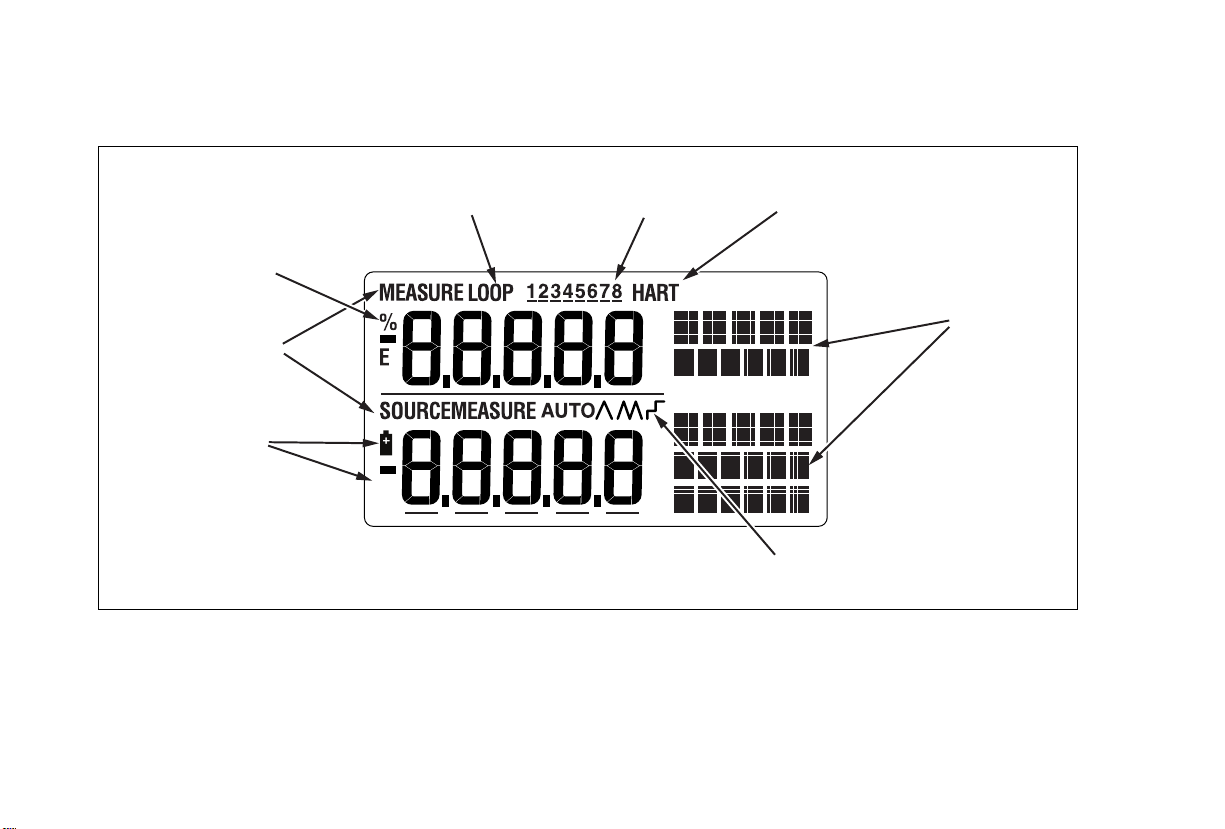
On page 13, replace Figure 4 with the following:
7/15 1
Page 3
Manual Supplement 726 Users
% Error
Indicators
Mode
Indicator
Low Battery
Symbol
Loop
Indicator
Figure 4. Elements of a Typical Disp lay
Memory Locations
for Calibrator Setups
HART Mode
Indicator
Units
Display
Auto
Ramp
2 7/15
Page 4

726 Users Manual Supplement
On page 14, under Configuration Menus, add the following under the last bullet:
• Step time
• Ramp time
On page 15, under Shut Down Mode, replace numbered steps with the following:
1. Press until SHUT DOWN appears on the display.
2.
Use and to increase or decrease the time.
3. Use and to turn on and off.
4. Press to save the setting.
On page 16, under Hart
Resistor ON/OFF, replace step 2 with the following:
2. Use or and to toggle ON and OFF.
Add the following below the Note:
Step Time
Step Time sets the ramp step time from 1 sec to 99 sec.
1. Press until STEP TIME appears on the display.
2. Use and to set the step time.
3. Press to save the setting.
7/15 3
Page 5

Manual Supplement 726 Users
Ramp Time
Ramp Time sets the ramp time from 5 sec to 99 sec.
1. Press until RAMP TIME appears on the display.
2. Use and to set the ramp time.
3. Press to save the setting.
On page 25, Table 6, add the following:
Cu10 10 Ω Copper 0.0042 Ω/°C -100 to 250
On page 42, under Auto Ramping the Output, replace the 2
nd
and 3rd bullets with the following:
• 0 % - 100 % - 0 % configurable time smooth ramp. Set ramp time using configuration
menu.
• 0 % - 100 % - 0 % Stair-step ramp in 25 % steps, pausing at each step. Set ramp
time using configuration menu. Steps are listed in Table 7.
On page 60, under Frequency Measurement, add the following to the bottom of the table:
Sensitivity: 1 V peak to peak minimum
Waveform: Squarewave
4 7/15
Page 6

726 Users Manual Supplement
On page 62, change the Range entries for “Thermocouple in mV read” and “Thermocouple in
mV source”:
From:
To:
-10 °C to 75 °C
-10 mV to 75 mV
On page 63, under the RTD Accuacy (Read and Source) (ITRS-90) table, replace the CU10 row
with the following:
Cu10 -100.0 250.00 1.8
On page 64, under Pulse Read and Pulse Source, replace the Frequency entry with the
following:
2 CPM to 15 kHz
7/15 5
Page 7

Manual Supplement 726 Users
Change #2, 57003
On page 5, add the following under Caution:
Static Sensitive
The 726 MEASURE/SOURCE terminals are ESD (electro-static discharge) sensitive to
levels above ± 4 kV. The Calibrator can experience temporary loss of measurement or
source functionality, which may require operator intervention to restore product
function, or even cause permanent damage. In general, a disruptive ESD event will
only occur during connection of the test leads to the circuits being measured or if the
operator is carrying a large static charge and touches the Calibrator terminals. The
most common cause of ESD is the user carrying the Calibrator across a carpet, or
other similar triboelectric activity, before they connection to the circuit being
measured.
On page 59, in the notes under DC mA Measurement and Source, add:
When in a 3 V/m radiated EM field ≤ 300 MHz, floor counts are increased to 30 μA in mA Read.
On page 60, in the notes under Ohms Measurement add:
When in a 3 V/m radiated EM field ≤ 300 MHz, floor counts are increased to 2.5 Ω in 400 Ω range.
6 7/15
Page 8

726 Users Manual Supplement
On page 61, in the notes under Temperature, Thermocouples add:
When in a 3 V/m radiated EM field ≤ 300 MHz, add 2 % of range for all TC types.
Change #3
On page 54, Table 8:
Change:
To:
8
8 Fluke-7XX Test Lead Set 3397308 1
Test lead, red
Test lead, black
688051
688066
1
1
Change #4, 67391, 171, 512
On page 7, under Table 2, add:
Symbol
Consult user documentation.
Conforms to relevant Australian EMC standards.
Conforms to relevant South Korean EMC Standards.
7/15 7
Meaning
Page 9

Manual Supplement 726 Users
On page 65, under General Specifications, replace the Safety section and add:
Safety IEC 61010-1: Pollution Degree 2
Electromagnetic Compatibility
(EMC)
International IEC 61326-1: Portable Electromagnetic Environment
CISPR 11: Group 1, Class A
Group 1: Equipment has intentionally generated and/or uses conductively-coupled radio
frequency energy that is necessary for the internal function of the equipment itself.
Class A: Equipment is suitable for use in all establishments other than domestic and
those directly connected to a low-voltage power supply network that supplies buildings
used for domestic purposes. There may be potential difficulties in ensuring
electromagnetic compatibility in other environments due to conducted and radiated
disturbances.
Emissions that exceed the levels required by CISPR 11 can occur when the equipment
is connected to a test object.
Korea (KCC)
USA (FCC) 47 CFR 15 subpart B. This product is considered an exempt device per clause 15.103.
Class A Equipment (Industrial Broadcasting & Communication Equipment)
Class A: Equipment meets requirements for industrial electromagnetic wave equipment
and the seller or user should take notice of it. This equipment is intended for use in
business environments and not to be used in homes.
8 7/15
 Loading...