

Page 1

421D
Distance Meter
Users Manual
September 2009
© 2009 Fluke Corporation. All rights reserved. Specifications are subject to change without notice.
All product names are trademarks of their respective companies.
Page 2

LIMITED WARRANTY AND LIMITATION OF LIABILITY
Each Fluke product is warranted to be free from defects in material and workmanship under normal use and service. The warranty period is
two years and begins on the date of shipment. Parts, product repairs, and services are warranted for 90 days. This warranty extends only to
the original buyer or end-user customer of a Fluke authorized reseller, and does not apply to fuses, disposable batteries, or to any product
which, in Fluke's opinion, has been misused, altered, neglected, contaminated, or damaged by accident or abnormal conditions of operation
or handling. Fluke warrants that software will operate substantially in accordance with its functional specifications for 90 days and that it has
been properly recorded on non-defective media. Fluke does not warrant that software will be error free or operate without interruption.
Fluke authorized resellers shall extend this warranty on new and unused products to end-user customers only but have no authority to
extend a greater or different warranty on behalf of Fluke. Warranty support is available only if product is purchased through a Fluke
authorized sales outlet or Buyer has paid the applicable international price. Fluke reserves the right to invoice Buyer for importation costs of
repair/replacement parts when product purchased in one country is submitted for repair in another country.
Fluke's warranty obligation is limited, at Fluke's option, to refund of the purchase price, free of charge repair, or replacement of a defective
product which is returned to a Fluke authorized service center within the warranty period.
To obtain warranty service, contact your nearest Fluke authorized service center to obtain return authorization information, then send the
product to that service center, with a description of the difficulty, postage and insurance prepaid (FOB Destination). Fluke assumes no risk
for damage in transit. Following warranty repair, the product will be returned to Buyer, transportation prepaid (FOB Destination). If Fluke
determines that failure was caused by neglect, misuse, contamination, alteration, accident, or abnormal condition of operation or handling,
including overvoltage failures caused by use outside the product’s specified rating, or normal wear and tear of mechanical components,
Fluke will provide an estimate of repair costs and obtain authorization before commencing the work. Following repair, the product will be
returned to the Buyer transportation prepaid and the Buyer will be billed for the repair and return transportation charges (FOB Shipping
Point).
THIS WARRANTY IS BUYER'S SOLE AND EXCLUSIVE REMEDY AND IS IN LIEU OF ALL OTHER WARRANTIES, EXPRESS OR
IMPLIED, INCLUDING BUT NOT LIMITED TO ANY IMPLIED WARRANTY OF MERCHANTABILITY OR FITNESS FOR A PARTICULAR
PURPOSE. FLUKE SHALL NOT BE LIABLE FOR ANY SPECIAL, INDIRECT, INCIDENTAL OR CONSEQUENTIAL DAMAGES OR
LOSSES, INCLUDING LOSS OF DATA, ARISING FROM ANY CAUSE OR THEORY.
Since some countries or states do not allow limitation of the term of an implied warranty, or exclusion or limitation of incidental or
consequential damages, the limitations and exclusions of this warranty may not apply to every buyer. If any provision of this Warranty is held
invalid or unenforceable by a court or other decision-maker of competent jurisdiction, such holding will not affect the validity or enforceability
of any other provision.
11/99
Fluke Corporation
P.O. Box 9090
Everett, WA 98206-9090
U.S.A.
Fluke Europe B.V.
P.O. Box 1186
5602 BD Eindhoven
The Netherlands
Page 3

Table of Contents
Title Page
Introduction .................................................................................................................... 1
How to Contact Fluke ..................................................................................................... 1
Use of the instrument ..................................................................................................... 1
Permitted use ............................................................................................................ 1
Prohibited use ........................................................................................................... 1
Limits of use .............................................................................................................. 2
Areas of responsibility ............................................................................................... 2
Responsibilities of the manufacturer (Fluke)......................................................... 2
Responsibilities of the manufacturer of non-Fluke accessories ............................ 2
Responsibilities of the person in charge of the instrument.................................... 2
Hazards in use........................................................................................................... 3
Precautions ............................................................................................................... 3
Safety Instructions.......................................................................................................... 3
Symbols..................................................................................................................... 3
Electromagnetic Compatibility (EMC) ........................................................................ 4
i
Page 4

421D
Users Manual
FCC statement (U.S.A only) .......................................................................................... 4
Laser classification.................................................................................................... 5
Integrated distance meter .................................................................................... 5
Laser Class 2 products: ....................................................................................... 5
Start-up.......................................................................................................................... 6
Inserting/replacing batteries...................................................................................... 6
Changing the reference point (multifunctional endpiece) .......................................... 7
Keypad...................................................................................................................... 8
Display ...................................................................................................................... 9
Menu functions .............................................................................................................. 10
Settings..................................................................................................................... 10
Navigation in the menu ........................................................................................ 10
General description .............................................................................................. 10
Setting the unit for distance measurements .............................................................. 12
Setting the unit for tilt measurements........................................................................ 12
Beep (BEEP)............................................................................................................. 12
Continuous laser ().............................................................................................. 12
Measuring with the tripod (TRIPOD)......................................................................... 12
Display - keypad illumination ().............................................................................. 13
Reset - returning the instrument to the factory settings (RESET) ............................. 13
Operation....................................................................................................................... 13
Switching on and off.................................................................................................. 13
CLEAR button........................................................................................................... 13
Display / keypad illumination..................................................................................... 13
Reference setting...................................................................................................... 13
Measuring...................................................................................................................... 14
Single distance measurement................................................................................... 14
Minimum/maximum measurement ............................................................................ 14
Functions ....................................................................................................................... 15
ii
Page 5

Contents (continued)
Addition / subtraction ................................................................................................. 15
Distance measuring .............................................................................................. 15
Area........................................................................................................................... 15
Volume ........................................................................................................................... 15
Tilt measurement ........................................................................................................... 16
Tilt sensor calibration................................................................................................. 16
Indirect horizontal distance........................................................................................ 17
Stake out function...................................................................................................... 17
Room corner angle function ...................................................................................... 18
Indirect measurement................................................................................................ 19
Indirect measurement - determining a distance using 2 auxilliary measurements 19
Indirect Measurement - determining a distance using 3 measurements............... 20
Indirect measurement - determining a chain value using 3 measurements .......... 20
Storage of constants/historical storage...................................................................... 21
Storage of a constant............................................................................................ 21
Recalling the constant .......................................................................................... 21
Historical storage .................................................................................................. 21
Timer (self-triggering) ................................................................................................ 21
Appendix ........................................................................................................................ 22
Message codes ......................................................................................................... 22
Technical data ........................................................................................................... 23
Measuring conditions................................................................................................. 25
Measuring range................................................................................................... 25
Target surfaces..................................................................................................... 25
Care and Cleaning..................................................................................................... 25
iii
Page 6

421D
Users Manual
iv
Page 7

Distance Meter
Introduction
Carefully read the Safety Instructions and the User
Manual before using this product.
How to Contact Fluke
To contact Fluke, call one of the following telephone
numbers:
• Technical Support USA: 1-800-44-FLUKE (1-800-
443-5853)
• Calibration/Repair USA: 1-888-99-FLUKE (1-888-
993-5853)
• Canada: 1-800-36-FLUKE (1-800-363-5853)
• Europe: +31 402-675-200
• Japan: +81-3-3434-0181
• Singapore: +65-738-5655
• Anywhere in the world: +1-425-446-5500
Or, visit Fluke's website at www.fluke.com
To register your product, visit http://register.fluke.com
.
To view, print, or download the latest manual supplement,
visit http://us.fluke.com/usen/support/manuals
.
Use of the instrument
Permitted use
• Measuring distances
• Computing functions, e. g. areas and volumes
• Measuring tilts
Prohibited use
• Using the instrument without instruction
• Using outside the stated limits
• Deactivation of safety systems and removal of
explanatory and hazard labels
• Opening of the equipment by using tools
(screwdrivers, etc.), as far as not specifically
permitted for certain cases
.
• Carrying out modification or conversion of the
product
1
Page 8

421D
Users Manual
• Use of accessories from other manufacturers without
the express approval of Fluke
• Deliberate or irresponsible behavior on scaffolding,
when using ladders, when measuring near machines
which are running, or near parts of machines or
installations which are unprotected
• Aiming directly into the sun
• Pointing the laser directly at people or animals in light
or dark conditions.
• Inadequate safeguards at the surveying site (for
example, when measuring on roads, construction
sites, etc.)
Limits of use
Note
See section “Technical Data”.
The Fluke 421D is designed for use in areas permanently
habitable by humans, do not use the product in explosion
hazardous areas or in aggressive environments.
Areas of responsibility
Responsibilities of the manufacturer (Fluke)
Fluke is responsible for supplying the product, including
the User Manual and original accessories, in a completely
safe condition.
Responsibilities of the manufacturer of non-Fluke accessories
The manufacturers of non-Fluke accessories for the 421D
are responsible for developing, implementing and
communicating safety concepts for their products. They
are also responsible for the effectiveness of these safety
concepts in combination with Fluke equipment.
Responsibilities of the person in charge of the instrument
W Warning
The person responsible for the instrument
must ensure that the equipment is used in
accordance with the instructions. This
person is also accountable for the
deployment of personnel and for their
training and for the safety of the equipment
when in use.
The person in charge of the instrument has the following
duties:
• To understand the safety instructions on the product
and the instructions in the User Manual.
• To be familiar with local safety regulations relating to
accident prevention.
• To inform Fluke immediately if the equipment
becomes unsafe.
2
Page 9

Distance Meter
Safety Instructions
Hazards in use
W Caution
Watch out for erroneous distance
measurements if the instrument is defective
or if it has been dropped or has been
misused or modified.
Precautions
Carry out periodic test measurements. Particularly after
the instrument has been subject to abnormal use, and
before, during and after important measurements.
Make sure the 421D optics is kept clean and that there is
no mechanical damage to the bumpers.
W Caution
In using the instrument for distance
measurements or for positioning moving
objects (for example, cranes, building
equipment, platforms, etc.) unforeseen
events may cause erroneous measurements.
Only use this product as a measuring sensor, not as a
control device. Your system must be configured and
operated in such a way, that in case of an erroneous
measurement, malfunction of the device or power failure
due to installed safety measures (for example, safety limit
switch), it is assured that no damage will occur.
~W Warning
Flat batteries must not be disposed of with
household waste. Care for the environment
and take them to the collection points
provided in accordance with national or local
regulations.
The product must not be disposed of with household
waste.
Dispose of the product appropriately in accordance with
the national regulations in force in your country.
Always prevent access to the product by unauthorized
personnel.
Product specific treatment and waste management
information can be downloaded from the Fluke home
page at http://www.fluke.com
dealer.
Safety Instructions
Symbols
The symbols used in the Safety Instructions have the
following meanings:
Indicates a potentially hazardous situation or
an unintended use which, if not avoided, will
result in death or serious injury.
or received from your Fluke
W Warning
3
Page 10
421D
Users Manual
W Caution
Indicates a potentially hazardous situation or
an unintended use which, if not avoided, may
result in minor injury and/or in appreciable
material, financial and environmental
damage.
Symbol Description
Do not dispose of this product as
~
unsorted municipal waste. Go to Fluke’s
website for recycling information.
* Warning. Laser
W
P
Important paragraphs which must be adhered to
in practice as they enabled the product to be
used in a technically correct and efficient
manner.
Electromagnetic Compatibility (EMC)
The term "electromagnetic compatibility" is taken to mean
the capability of the product to function smoothly in an
environment where electromagnetic radiation and
Risk of Danger. Important information.
See Manual.
Conforms to European Union directives.
Note
electrostatic discharges are present, and without causing
electromagnetic interference to other equipment.
W Warning
The 421D conforms to the most stringent
requirements of the relevant standards and
regulations. Yet, the possibility of it causing
interference in other devices cannot be
totally excluded.
W Caution
Never attempt to repair the product yourself.
In case of damage, contact Fluke
(www.fluke.com
).
FCC statement (U.S.A only)
This equipment has been tested and found to comply with
the limits for a Class B digital device, pursuant to part 15
of the FCC Rules. These limits are designed to provide
reasonable protection against harmful interference in a
residential installation.
This equipment generates, uses and can radiate radio
frequency energy and, if not installed and used in
accordance with the instructions, may cause harmful
interference to radio communications.
However, there is no guarantee that interference will not
occur in a particular installation.
4
Page 11

Distance Meter
FCC statement (U.S.A only)
If this equipment does cause harmful interference to radio
or television reception, which can be determined by
turning the equipment off and on, the user is encouraged
to try to correct the interference by one or more of the
following measures:
• Reorient or relocate the receiving antenna.
• Increase the separation between the equipment and
receiver.
• Connect the equipment into an outlet on a circuit
different from that to which the receiver is connected.
• Consult the dealer or an experienced radio/TV
technician for help.
W Warning
Changes or modifications not expressly
approved by Fluke for compliance could void
the user’s authority to operate the
equipment.
Laser classification
Integrated distance meter
The 421D produces a visible laser beam which emerges
from the front of the instrument.
It is a Class 2 laser product in accordance with:
• IEC60825-1 : 2007 "Radiation safety of laser
products"
Laser Class 2 products:
Do not stare into the laser beam or direct it towards other
people unnecessarily. Eye protection is normally afforded
by aversion responses including the blink reflex.
W Warning
Do not look directly into the beam with
optical aids. Looking directly into the beam
with optical aids (for example, binoculars,
telescopes) can be hazardous.
W Caution
Looking into the laser beam may be
hazardous to the eyes.
Do not look into the laser beam. Make sure the laser is
aimed above or below eye level. (particularly with fixed
installations, in machines, etc.)
5
Page 12

421D
Users Manual
Start-up
Inserting/replacing batteries
See figure {A}
1. Remove battery compartment lid and attach
handstrap.
2. Insert two AAA (LR3) batteries, observing correct
polarity.
3. Close the battery compartment again. Replace the
batteries when the symbol
the display.
Use alkaline batteries only.
Remove the batteries before any long period of
non-use to avoid the danger of corrosion.
flashes permanently in
Note
Note
A
6
Page 13

Distance Meter
Start-up
Changing the reference point (multifunctional endpiece)
See figure {B}.
B
1
2
The instrument can be adapted for the following
measuring situations:
• For measurements from an edge, fold out the
positioning bracket until it first locks in place. See
figure {C}.
C
• For measurements from a corner, open the
positioning bracket until it locks in place, then push
the positioning bracket lightly to the right to fold it out
fully. See figure {D}.
7
Page 14

421D
Users Manual
D
A built-in sensor automatically detects the orientation of
the positioning bracket and adjusts the zero point of the
instrument accordingly.
Keypad
See figure {E}:
1. Measure/Min Max/Power On
2. Plus (+)/Scroll up
3. Minus (-)/Scroll down
4. Area/volume
5. Tilt function/Stake out
6. Reference
7. Timer
8. Memory
9. Clear/off
10. Setup/mem/equal
11. Room corner/triangle angles
12. Indirect measurement (Pythagoras)
E
23
12
11
10
1
4
5
6
7
8
9
8
Page 15

Distance Meter
Start-up
Display
See figure {F}
1. Laser active
2. Reference (front)
3. Reference (rear)
4. Reference (corner stop)
5. Measuring with the tripod
6. Stake out function
7. Single Pythagorean measurement
8. Double Pythagorean measurement
9. Double (partial height) measurement
10. Illumination
11. Save constant value, call up constant value
12. Historical memory, call up values
13. Battery status
14. Timer
15. Area/volume
16. Tilt
17. Horizontal distance measurement using tilt
18. Room corner angle function
19. Menu
20. Continuous laser
21. Reset
22. Reference (tripod)
23. Beep
24. Circumference
25. Wall area
26. Ceiling area
27. Intermediate line 1
28. Intermediate line 2
29. Intermediate line 3
30. Summary line
31. Message code indicator
F
1
2
4
3
5
6
7
8
9
10
a
b
b
11 13
12 14
TIMER
a
max
b
min
15 16 17 18
?
193120
MENU
UNIT
TRIPOD
BEEP
RESET
ONOFF
21
22
23
27
24
28
25
29
26
30
9
Page 16

421D
Users Manual
Menu functions
Settings
The menu allows settings to be altered and permanently
stored. After switching off the device or replacing the
batteries the settings are stored.
Navigation in the menu
The menu allows settings to be made at the user level.
The instrument can be specifically configured to your
personal requirements.
General description
button (long press) brings up the MENU, the set
units and the symbol UNIT are displayed.
button (short press) pages through each menu
item. See figure {G}.
or button to make changes in menu items.
button (short press) brings up the next menu item.
A long press on the button in the menu confirms
the new settings made in the submenu items.
Pressing the button (short press) in the menu allows
you to quit the settings function without saving.
10
Page 17

Distance Meter
Menu functions
G
1
7
EXIT
6
2
3
4
5
11
Page 18

421D
Users Manual
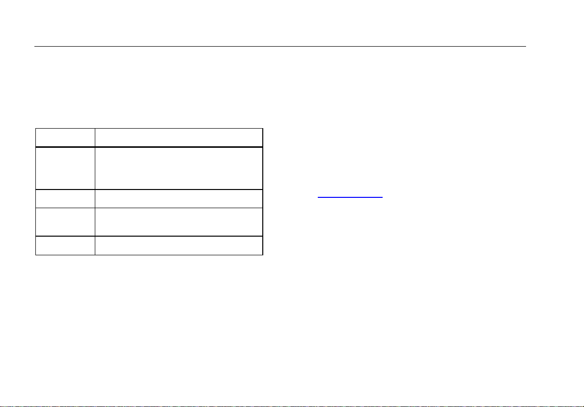
Setting the unit for distance measurements
The following units can be set:
Menu # Distance Area Volume
1.1 0.000 m 0.000 m2 0.000 m3
1.2 0.000
1.3 0.00 m 0.000 m2 0.000 m3
1.4 0.00 ft 0.00 ft2 0.00 ft3
1.5 0'00'' 1/32 0.00 ft2 0.00 ft3
1.6 0.0 in 0.00 ft2 0.00 ft3
1.7 0 1/32 in 0.00 ft2 0.00 ft3
0
m 0.000 m
2
0.000 m3
Setting the unit for tilt measurements
The following units can be set for tilt measurements:
Menu # Units for tilt
2.1 +/- 0.0°
2.2 0.00%
Beep (BEEP)
You can switch the beep on or off.
Menu #
Beep function
3.1 On
3.2 Off
Continuous laser ()
You can switch the continuous laser function on or off.
Menu #
With the continuous laser function set on, each press of
the button triggers a measurement. The laser
automatically switches off after 15 minutes.
Continuous laser function
4.1 On
4.2 Off
Measuring with the tripod (TRIPOD)
The reference must be appropriately adjusted in order to
be able to take correct measurements with a tripod. To do
this select the TRIPOD symbol in this menu item. You can
switch the reference on the tripod on or off. The setting
can be seen on the display
Menu #
Measuring with tripod function
5.1 On
5.2 Off
.
12
Page 19

Distance Meter
Operation
Display - keypad illumination ()
Automatic illumination of the display and the keypad can
be switched on or off.
Menu #
Illumination function
6.1 On
6.2 Off
Reset - returning the instrument to the factory settings (RESET)
The instrument has a RESET function. When you select
the menu function RESET and confirm, the instrument
defaults to the factory settings.
Menu # Reset function
7.1 On
7.2 Off
A reset returns the following values to their factory
settings:
• Reference (rear)
• Display illumination (ON)
• Beep (ON)
• Unit (m(mm))
• Stack and memory are erased
Note
All customized settings and stored values are
also lost.
Operation
Switching on and off
Switches on the instrument and laser. The display
shows the battery symbol until the next button is pressed.
Pressing this button for longer switches the
instrument off.
The instrument switches off automatically after six
minutes of inactivity.
CLEAR button
The last action is cancelled. While making area or
volume measurements, each single measurement can be
deleted and remeasured in series.
Display / keypad illumination
The instrument has a sensor that automatically switches
the display and keypad illumination on or off in response
to lighting conditions.
Reference setting
The default reference setting is from the rear of the
instrument. A special beep sounds whenever the
reference setting is changed.
13
Page 20

421D
Users Manual
Press this button (short press) to take the next
measurement from the front edge
After a measurement the reference returns automatically
to the default setting (rear reference). See figure {H}.
.
H
1
Measure
Min Max
2
Press this button (long press) to set the reference to
the front. Does not return to default (rear) reference.
Press this button, the rear reference is set again.
Measuring
Single distance measurement
Press to activate the laser. Press again to trigger
the distance measurement.
The result is displayed immediately.
Minimum/maximum measurement
This function allows the user to measure the minimum or
maximum distance from a fixed measuring point. It can
also be used as to determine spacings. See figure {I}.
I
Min. Max.
It is commonly used to measure room diagonals
(maximum values) or horizontal distances (minimum
values).
Press and hold down this button until you hear a
beep. Then slowly sweep the laser back and forth and up
and down over the desired target point - (for example,
into the corner of a room).
14
Page 21

Distance Meter
Functions
Press to stop continuous measurement. The
values for maximum and minimum distances are shown in
the display as well as the last measured value in the
summary line.
Functions
Addition / subtraction
Distance measuring
The next measurement is added to the previous one.
The next measurement is subtracted from the
previous one.
This process can be repeated as required. Press
this key to display result. The result is always shown in
the summary line with the previous value in the second
line.
The last step is cancelled.
Area
Press once. The symbol appears in the display.
Press this button to take the first length
measurement (for example, length).
Press it again to take the second length
measurement (for example, width).
The result is displayed in the summary line.
Press the button (long press) to calculate the
circumference.
Volume
Press this button twice. The symbol appears in the
display.
Press this button to take the first length
measurement (for example, length).
Press this button to take the second length
measurement (for example, width).
Press this button to take the third length
measurement (for example, height). The value is shown
in the second line.
The volume then appears in the summary line.
Press the button (long press) to display additional
room information such as ceiling/floor area, surface area
of the walls, circumference.
Ceiling/floor area
Wall area
Circumference
15
Page 22

421D
Users Manual
Tilt measurement
Note
The inclination sensor measures tilts between
±45°.
Note
During tilt measurement the instrument should
be held without a transverse tilt (±10°).
Press this button once to activate the tilt sensor. The
symbol appears in the display. The tilt is continuously
shown as ° or % depending on the setting.
Press to measure the inclination and the distance.
See figure {J}.
J
Tilt sensor calibration
The user can calibrate the device’s tilt sensor. The angle
sensor is switched on by pressing the once. Then two
measurements are taken on a flat surface. The first
measurement is taken and a note is made of the
measured angle a. The device is then turned through
exactly 180 °, the second measurement is taken and a
note is made of the measured angle b. The value x to
which the device must be corrected is calculated as
follows:
x = -(a+b)/2
The calibration mode is then entered by pressing keys
and the both at the same time for 2 seconds.
The correction value x can be entered here using the
and keys. The entered value is stored and
implemented by pressing the key.
16
Page 23

Distance Meter
1
2
3
Tilt measurement
Indirect horizontal distance
This function allows the user to determine a horizontal
distance even when the line-of-sight is blocked by an
object or obstacle. See figure {K}.
K
Press this button twice and the following symbol
appears in the display .
Press this button to measure tilt and diagonal
distance. The summary line displays the result as the
direct horizontal distance.
Stake out function
Two different distances (a and b) can be entered into the
instrument and can then be used to mark off defined
measured lengths, for example, in the construction of
wooden frames.
See figure {L}.
L
1
2
0.625 m
0.625 m
0.625 m
b
Entering stake out distances:
Press this button three times and the stake out
function symbol appears in the display .
The value (a) and the corresponding intermediate line
flash.
By using and , you can adjust the values (first a
and then b) to suit the desired stake out distances.
Holding the buttons down increases the rate of change of
the values.
Once the desired value (a) has been reached it can be
confirmed with the button.
The value (b) and the intermediate line flashes (the
defined value (a) is automatically adopted). Value (b) can
be entered using and .
a
b
a=b
3
0.625 m
b
0.625 m
1.025 m
a
b
17
Page 24

421D
Users Manual
The defined value (b) is confirmed with the button
and starts the stake out laser measurement.
The display shows required stake out distance in the
summary line between the stake out point (first a and
then b) and the instrument (rear reference).
If the 421D is then moved slowly along the stake out line
the displayed distance decreases. The instrument starts
to beep at a distance of 0.1 m from the next stake out
point.
The arrows in the display
the 421D needs to be moved in order to achieve the
defined distance (either a or b). As soon as the stake out
point is reached the beep changes and the arrows in the
display disappear.
The function can be stopped at any time by pressing the
button.
indicate in which direction
Room corner angle function
The angles in a triangle can be calculated by measuring
the three sides. This function can be used e. g. to check a
right-angled room corner. See figure {M}.
M
Press this button and the room corner symbol appears
in the display .
Mark the reference points to the right and left (d1/d2) of
the angle to be measured.
Press this button to measure the first (short) side of
the triangle (d1 or d2).
Press this button to measure the second (short)
side of the triangle (d1 or d2).
Press this button to measure the third (long) side of
the triangle (d3).
The result is displayed in the summary line as the room
corner angle.
18
Page 25

Distance Meter
Tilt measurement
Indirect measurement
The instrument can calculate distances using Pythagoras’
theorem.
Note
Make sure you adhere to the prescribed
sequence of measurement:
• All target points must be in a horizontal or
vertical plane.
• The best results are achieved when the
instrument is rotated about a fixed point (for
example, with the positioning bracket fully
folded out and the instrument placed on a
wall).
• The minimum/maximum function can be
used -see explanation in "Measuring ->
Minimum/maximum measurement". The
minimum value must be used for
measurements at right angles to the target;
the maximum distance for all other
measurements.
Note
Make sure that the first measurement and the
distance to be measured are at right angles. Use
the Minimum/maximum function, as explained in
"Measuring -> Minimum/maximum
measurement".
Indirect measurement - determining a distance using 2 auxilliary measurements
See figure {N}.
N
1
2
For example, for measuring building heights or widths. It
is helpful to use a tripod when measuring heights that
require the measurement of two or three measurements.
Press this button once, the display shows .
The laser is switched on.
Aim at the upper point (1) and trigger the
measurement. After the first measurement the value is
adopted. Keep the instrument as horizontal as possible.
Press and hold down this button to trigger
continuous measurement, sweep the laser back and forth
and up and down over the ideal horizontal target point.
19
Page 26

421D
Users Manual
Press to stop continuous measurement (2). The
result is displayed in the summary line, the partial results
in the secondary line.
Indirect Measurement - determining a distance using 3 measurements
See figure {O}.
O
1
2
3
Press this button twice; the display shows the
following symbol . The laser is switched on.
Aim at the upper point (1) and trigger the
measurement. After the first measurement the value is
adopted. Keep the instrument as horizontal as possible.
Press and hold down this button to trigger
continuous measurement, sweep the laser up and down
over the ideal horizontal target point.
Press to stop continuous measurement (2). The
value is adopted. Aim at the lower point and press
this button to trigger the measurement (3). The result is
displayed in the summary line, the partial results in the
secondary lines.
Indirect measurement - determining a chain value using 3 measurements
See figure {P}.
P
1
2
3
For example, determining the height between point 1 and
point 2 using three target points.
Press this button three times; the display shows the
following symbol . The laser is switched on.
Aim at the upper point (1).
Press this button and trigger the measurement.
After the first measurement the value is adopted. The
display flashes (2).
fig_p.eps
20
Page 27

Distance Meter
Tilt measurement
Triggers the measurement. After the second
measurement the value is adopted. The display flashes
(3). Keep the instrument as horizontal as possible.
Press and hold down this button to trigger
continuous measurement. Sweep the laser up and down
over the ideal horizontal target point.
Press this button to end continuous measurement.
The result is displayed in the summary line, the partial
results in the secondary lines.
Storage of constants/historical storage
Storage of a constant
You can store and recall a frequently used value for
example, height of a room. Measure the desired distance,
press and hold the button until the device beeps to
confirm storage.
Recalling the constant
Press this button once to recall the constant and
make it available for further calculations by pressing
button .
Historical storage
Press this button twice and the previous 20 results
(measurements or calculated results) are shown in
reverse order.
The and buttons can be used for navigation.
Press this button to use a result from the summary
line for further calculations.
Pressing the and buttons at the same time
erases all the values in historical storage.
Timer (self-triggering)
Press this button to set a 5-second time delay.
or
Press and hold down this button until the desired time
delay is reached (max. 60 seconds).
Press to begin the timer. The remaining seconds
until measurement (for example, 59, 58, 57...) are
displayed in a countdown. The last 5 seconds are
counted down with a beep. After the last beep the
measurement is taken and the value is displayed.
Note
The timer can be used for all measurements.
21
Page 28

421D
Users Manual
Appendix
Message codes
All message codes are displayed with either or "Error".
The following errors can be corrected:
Cause Remedy
156
160
204
252
253
255
256
Transverse tilt
greater than 10°
Main tilt direction,
angle too high
(>45°)
Calculation error Repeat procedure
Temperature too
high
Temperature too
low
Receiver signal
too weak,
measurement
time too long,
distance >100 m
Received signal
too strong
Hold the instrument
without any
transverse Tilt
Measure angle up to
max. ±45°
Cool down instrument
Warm up instrument
Use target plate
Target too reflective
(use target plate)
257
260
Error Cause Remedy
Error Hardware error Switch on/off the
Wrong
measurement,
background
brightness too
high
Laser beam
interrupted
Darken target
(measure in different
lighting conditions)
Repeat measurement
device several
times. If the symbol
still appears, then
your instrument is
defective. Please
call your dealer for
assistance.
22
Page 29

Distance Meter
Appendix
Technical data
Distance measurements:
Measuring accuracy up to 10 m
(2 σ, standard deviation)
Power Range Technology™:
Range (use target plate from
about 80m)
Smallest unit displayed 0.1 mm
Distance measurement √
Minimum/maximum
measurement, Continuous
measurement
Area/volume calculation of room
data
Addition / subtraction √
Indirect measurement using
Pythagoras
Tilt measurements:
Tilt sensor:
Accuracy (2 σ, standard
deviation)
- to laser beam
- to the housing
Indirect measurement using tilt
sensor (direct horizontal
distance)
Angle measurement using tilt
sensor(± 45°)
typically: ± 1.5
mm* (± 1/16 in*)
0.05 m to 100 m
± 0.3°
± 0.3°
General:
Laser class
II
Laser type 635 nm, < 1 mW
∅ laser point
(at distances)
Automatic laser switch-
6 / 30 / 60 mm
(10 / 50 / 100 m)
after 3 min
off
√
Automatic instrument
after 6 min
switchoff
√
Display illumination √
Keypad illumination √
√
Multifunctional endpiece √
Timer (self-triggering) √
Save constant value √
Historical storage (20
√
values)
Tripod thread √
√
√
Battery life,
Type AAA, 2 x 1.5 V
NEDA 24A/IEC LR03
Protection against
splashes and dust
up to 5 000
measurements
IP 54, dust-proof,
splash-proof
23
Page 30

421D
Users Manual
Dimensions 125 x 45 x 25 mm
Weight (with batteries) 110 g
Temperature range:
Storage
Operation
Maximum altitude 3500 m (AMSL)
Maximum relative
humidity
Pollution degree 2
Safety
EMC
*maximum deviation occurs under unfavorable
conditions such as bright sunlight or when measuring to
poorly reflecting or very rough surfaces. Measuring
accuracy between 10 m and 30 m may deteriorate to
approx. ± 0.025 mm/m, for distances above 30 m to ±
0.1 mm/m.
-25 °C to +70°C
(13 °F to +158 °F)
-10 °C to +50 °C
(14 °F to +122 °F)
85% at 20 °F to 120
°F (-7 °C to 50 °C)
CAN/CSA-C22.2 No.
61010-1-04, UL Std.
No. 61010-1 (2nd
Edition), ISA-
82.02.01, IEC
Standard No. 610101:2001, and
EN60825-1:2007
(Class II)
61326-1:2006
24
Page 31

Distance Meter
Appendix
Measuring conditions
Measuring range
The range is limited to 100 m.
At night or dusk and if the target is in shadow the
measuring range without target plate is increased.
Use a target plate to increase the measurement range
during daylight or if the target has poor reflection
properties.
Target surfaces
Measuring errors can occur when measuring toward
colorless liquids (for example, water) or dust free glass,
Styrofoam or similar semi-permeable surfaces.
Aiming at high gloss surfaces may deflect the laser beam
and lead to measurement errors.
Against non-reflective and dark surfaces the measuring
time may increase.
Care and Cleaning
Do not immerse the instrument in water. Wipe off dirt with
a damp, soft cloth. Do not use aggressive cleaning
agents or solutions. Handle the instrument as you would
a telescope or camera.
25
Page 32

421D
Users Manual
26
 Loading...