

Page 1
Clamp meter readings:
problems and solutions
Application Note
A motor trips on overload.
Visual and physical inspection reveals no abnormalities.
There is no smell of burnt insulation, the load appears normal,
the coupling is intact, ambient temperature is not above
the nameplate specified value
of 40 °C (104 °F). As expected,
however, the motor is too hot to
touch. The next obvious troubleshooting tactic is to measure
the amperage the motor draws
while running. Since a small
increase in current flow to a
motor produces a proportionately
larger amount of heat, motor
amperage exceeding nameplate values should be carefully
investigated as a possible cause.
These overload trips, though
often caused by motor loading
issues, can also indicate bearing
failure, insulation breakdown or
voltage unbalance.
After you ensure that all safety
requirements for working near
energized components are satisfied, open the fuse disconnect
door in preparation for using
your clamp meter to measure
current. Once again, a visual
inspection reveals no obvious
problems. You begin to clamp
around a motor phase conductor
at the bottom of a fuse—and now
the problems begin.
Clamping around a phase
conductor
When you use a clamp meter it
is necessary to clamp around
only one phase conductor at a
time. When current flows to a
conductor it produces a magnetic
field around the conductor. The
more current, the stronger the
magnetic field. The magnetic
field induces a voltage into the
clamp portion of the meter. The
meter reading will be proportional to the amount of voltage
induced into the clamp. Therefore, reading the current flow
through a conductor requires
that only the magnetic field
produced by that one conductor be induced into the clamp.
Clamping around two or more
conductors will cause the
magnetic fields to cancel each
other and the resultant reading,
if not “zero,” will be completely
erroneous.
So, what is the problem
when clamping around only
one conductor? Have you ever
tried getting a clamp around a
10 AWG (American wire gauge)
solid conductor with inadequate
conductor length inside the
box? Have you ever tried pulling
away one 2 AWG conductor from
two others in an attempt to get
that clamp to fit? Sometimes
two of the conductors can be
reached fairly easily, but clamping around the third conductor
may be difficult. In some cases,
the clamp you are using may
simply not be big enough to go
around the conductor you need
to measure. You may need to
clamp around two conductors in
parallel. Each set of measurements will produce its own
unique problems.
F r o m t h e F l u k e D i g i t a l L i b r a r y @ w w w . f l u k e . c o m / l i b r a r y
Page 2
Safety is always a prime
consideration. Even when you
wear the appropriate shock and
arc-flash protection, having to
push and pull on live conductors
is not an enjoyable task and can
be dangerous. Conductors come
loose from underneath terminals.
Conductor insulation scraped off
during installation can come in
contact with the metal enclosure
when clamping around conductors. The phase-to-ground fault
can instantly escalate into a
phase-to-phase arcing fault with
potentially catastrophic arc-flash
results. There are no guarantees
anytime you are exposed to
energized conductors and circuit
parts. And, probing about those
conductors with the clamp meter
can only compound the problem.
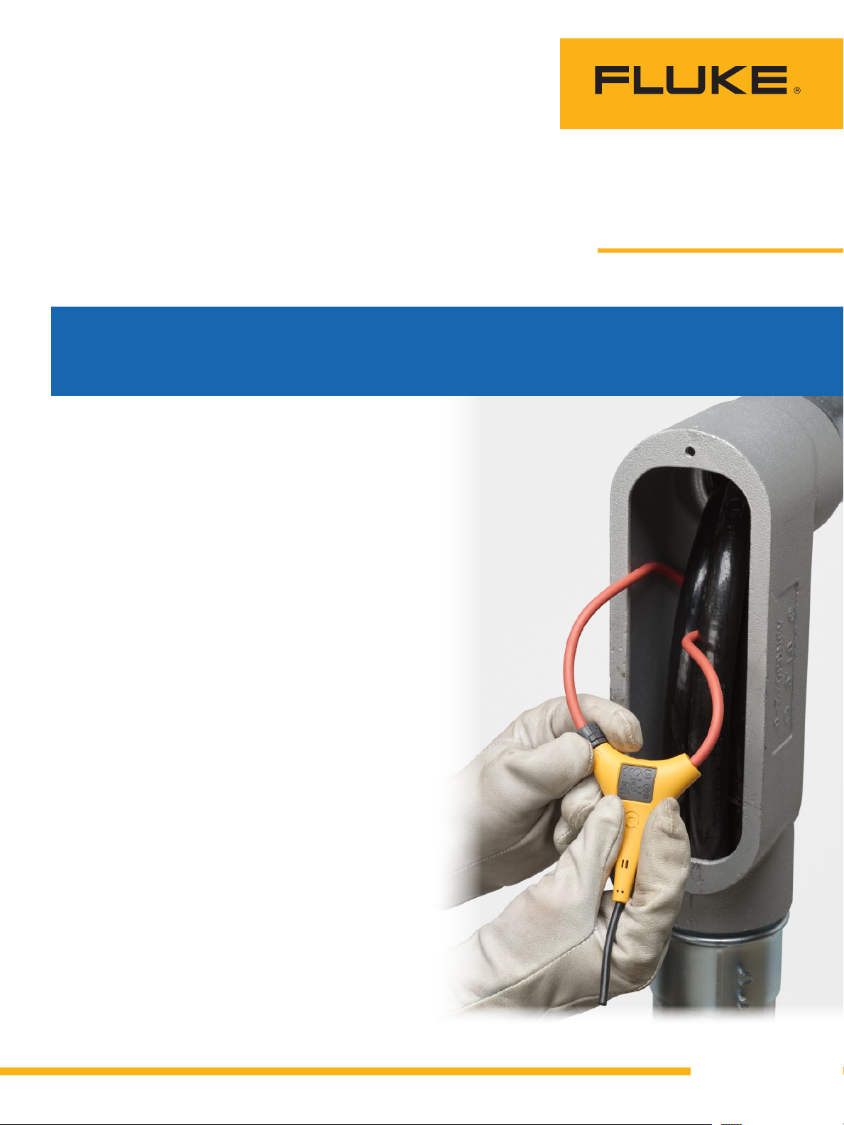
The solution to the above
problems is a flexible clamp.
Weaving a flexible clamp around
a conductor means not pulling
and tugging on it to move it from
adjacent conductors. Whether
dealing with the 10AWG solid
conductor or a 2 AWG (or larger)
stranded conductor, installing
the flexible clamp is simpler
and unquestionably much safer.
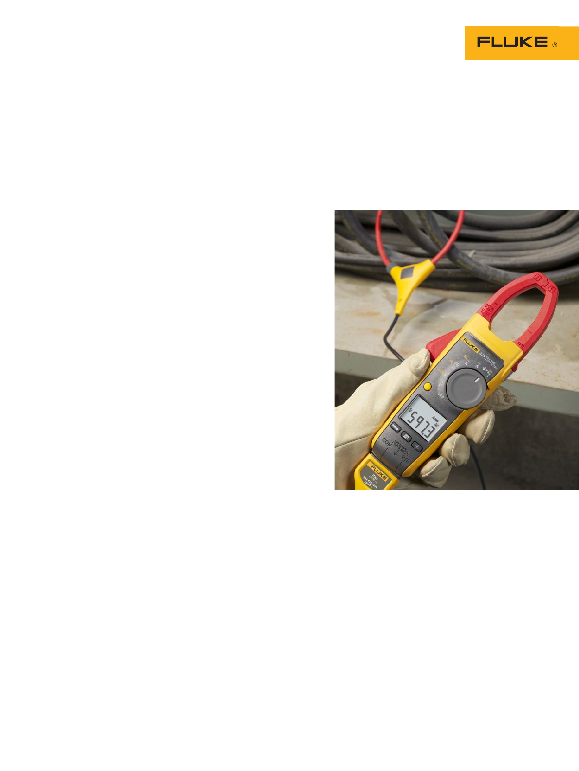
The problem has always been
that flexible clamps were typically found only on equipment
such as data loggers and power
quality analyzers, and were not
available for the standard clamp
meter used by professionals in
the field. Not true anymore, as
Fluke now offers true-rms ac/
dc clamp meters that utilize the
iFlex
™ flexible current probe.
One model even offers remote
display.
Determining inrush
current
When an ac motor starts it will
draw more current than its full
load value on the nameplate.
How much more current depends
on the load on the motor when
it starts and the code letter on
the nameplate. Excessive starting torque requirements or low
system voltages can result in
excessive inrush current during
start-up. Determining inrush
current can be tough with a
digital meter. Values change
rapidly and determining the
actual inrush value can be difficult. Min, max, average and
inrush recording features of the
Fluke models allow the meter
to capture variations automatically. Also, electronics filter out
noise and capture motor starting current exactly as the circuit
protection sees it. That means
what you see on the meter is
the same value sensed by the
overloads, time-delay fuses and
inverse-time circuit breakers.
Another problem is that inrush
current values may exceed the
maximum value read by the
meter. For example, a 460 volt,
250 horsepower motor should
draw no more than 302 amps
at full load. Inrush currents for
such a motor starting under full
load may be 1,500 to 2,000
amps. Determining the inrush
value can be important in diagnosing motor overload problems.
Obviously the meter must be
capable of reading such values.
Most clamp meters read a maximum value of 400 amps. Some
of the new Fluke clamp meters
have a 1000 amp limitation
with the fixed jaw and all have
a 2500 amp maximum current
measurement with the iFlex
™.
That means you can measure
the running current on a 460
volt, 500 horsepower motor!
Beyond motors
Certainly not all clamp-on
ammeter readings are taken on
motors. Current readings must
be taken on all types of nonlinear loads. Line side currents
on uninterrupted power supply
(UPS) systems and variablesystem drives (VFDs) must
be measured. Lighting loads
containing electronic ballasts, branch circuits supplying
computers, printers and copy
machines must all be measured.
The new Fluke true-rms clamp
meters feature a low pass filter,
allowing for accurate readings
on such nonlinear equipment.
When taking clamp meter
readings you should be ready for
problems. Remember that safety
is number one. And make sure
you have the right measurement
tool for the job—one that allows
for safe and accurate readings,
can measure the current range
you need, and even provide
remote display for both safety
and convenience.
Fluke. Keeping your world
up and running.
Fluke Corporation
PO Box 9090, Everett, WA 98206 U.S.A.
Fluke Europe B.V.
PO Box 1186, 5602 BD
Eindhoven, The Netherlands
For more information call:
In the U.S.A. (800) 443-5853 or
Fax (425) 446-5116
In Europe/M-East/Africa +31 (0) 40 2675 200 or
Fax +31 (0) 40 2675 222
In Canada (800)-36-FLUKE or
Fax (905) 890-6866
From other countries +1 (425) 446-5500 or
Fax +1 (425) 446-5116
Web access: http://www.fluke.com
©2010 Fluke Corporation.
Specifications subject to change without notice.
Printed in U.S.A. 10/2010 3949064A A-EN-N
Modification of this document is not permitted
without written permission from Fluke Corporation.
®
2 Fluke Corporation Clamp meter readings: problems and solutions
 Loading...