

Page 1
Troubleshooting 4 mA
to 20 mA controls,
ethanol style
In this operation, downtime is
not an alternative
Field
Applications
Case
Study
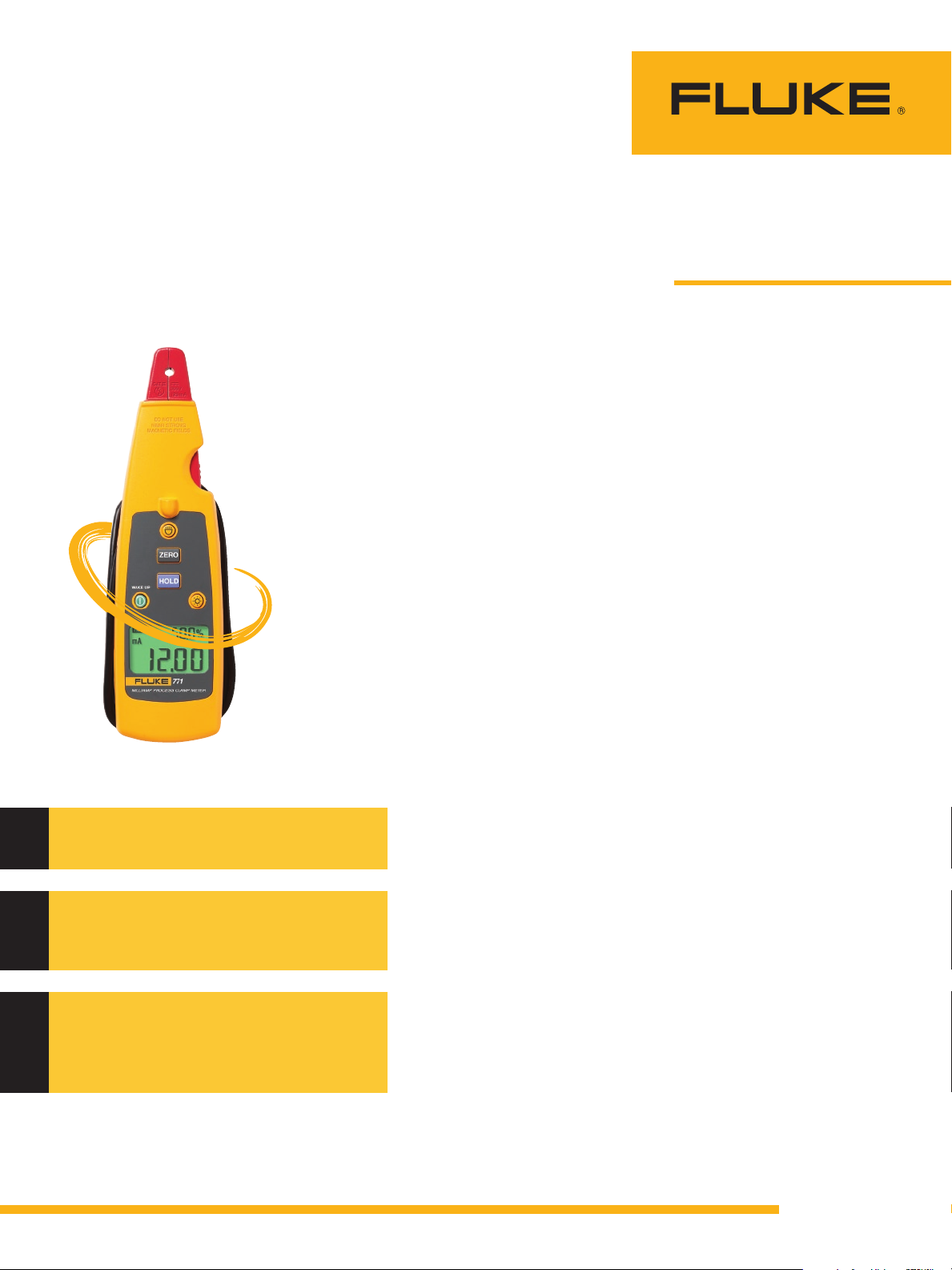
Tool: Fluke 771 Miliamp Process
Clamp Meter
Profile: Bruce Yenzer, instrumentation
technician, Siouxland Energy and
Livestock Cooperative
Measurements: Troubleshooting
live 4-20 mA controls for temperature,
pressure, flow, and pH devices and
valves
An ethanol production plant is
a storehouse of process control
technologies and a great venue
for illustrating the enduring
benefits of 4 mA to 20 mA
technology. Ask Bruce Yenzer,
an instrumentation technician
at the Siouxland Energy & Livestock Cooperative (Sioux Center,
IA). He “keeps the gears oiled”
in an ethanol production facility that manufactures 60 million
gallons of the alternative fuel
annually. Control devices at
the plant measure temperature, pressure, flow, pH, “and a
whole myriad of parameters,”
says Yenzer. And what all the
control devices have in common
is that they output a 4 mA to
20 mA signal—more or less the
industry standard of control
instrumentation. “I also have
a vast array of proportional
devices—valves—that are fed a
4 mA to 20 mA signal. 4 mA to
20 mA is our lifeblood.”
However, the simplicity of
the 4 mA to 20 mA current
loop masks the complexity of
the challenge to keep a plant
running optimally and reveals a
basic limitation of conventional
electronic measurement tools.
Let’s look deeper.
Measuring current with a
multimeter requires making a
connection within the circuit
under test, which often requires
powering down the circuit. Of
course, that could mean shutting down power to a complex,
dynamic system in which
Application Note
performance is measured in
thousands of dollars of revenue
per hour. “In a plant like this,
where production is paramount—we’re online 24 hours
a day—closing a valve or shutting down a device can have
far-reaching effects throughout
the process and the plant,” says
Yenzer. “If I were using a multimeter to troubleshoot a circuit, I
would have to break the circuit
and stop the process, which
would cause the valves to slam
shut and ‘deadhead’ the pump.
That could cause myriad problems. Taking my measurements
while things are running is the
best of all possible worlds.”
The other limitation of a
multimeter or ammeter in
Yenzer’s application? Inserting the meter within the circuit
changes the resistance of the
circuit—even if slightly—and can
skew a current measurement.
Enter the clamp meter (a name
derived from “clamp-on ammeter”). Because a clamp meter
“clamps” around an individual
wire, no disruption to the circuit
is required.
“I use the Fluke 771 Milliamp
Clamp Meter almost daily. Used
to be, I had to break the circuit
and insert my meter, which
meant I had to shut down the
circuit. The 771 allows me to
take my measurement and
to perform calibration while
online, with no interruption of
the circuit whatsoever.”
From the Fluke Digital Library @ www.fluke.com/library
Page 2

Going with the flow
“Ethanol is like other chemical production, says Yenzer.
“Using corn fermentation and
extracting the alcohol involves,
quite literally, thousands of
transmitters—constantly taking
measurements and reporting
back to the DCS.” The majority of SELC’s operations are
controlled from computers that
are part of a DCS. The system,
he says, can often run automated, with occasional manual
intervention from facility operators.
“We know what kind of flow
we should be getting through
a pipe. If an operator notices
that the flow is wrong, but the
DCS says the valve is adjusted
correctly to 50 % open, I can
place the 771 on the signal
lines coming in, verify that they
are correct, and use that data to
verify that the valve is open to
the proper position. Typically,
the signal is not getting to the
valve. We are in a nasty environment for electronics—high
moisture and high heat—and
that can cause malfunctions in
the wiring, in the computers,
the terminals, or the connection
to the device.”
Or, he says, the valve itself
might require an adjustment—
essentially an impromptu calibration. The 4 mA to 20 mA
current-to-pressure transducer
at the device would output a
3 psi to 15 psi pressure signal
that actually controls the valve.
“I could use this signal to get a
pneumatic response to control
the valve,” says Yenzer. “Less
frequently, I could have a fuse
blown, could have a bad output
on my computer card, or could
have a bad rack in the card
cage.”
In the loop
The 4 mA to 20 mA current
loop is a common method of
transmitting sensor information
in many industrial processmonitoring applications—
typically in systems monitoring
2 Fluke Corporation Troubleshooting 4 mA to 20 mA controls, ethanol style
pressure, temperature, pH, flow,
or other physical factors. These
systems employ the familiar two-wire, 4 mA to 20 mA
current loop, in which a single
twisted-pair cable supplies
power to a module and also
carries the output signal.
The loop’s operation is
straightforward: a sensor’s
output voltage is first converted
to a proportional current, with
4 mA normally representing
the sensor’s zero-level output
and 20 mA representing the
sensor’s full-scale output. A
reading of 20 mA means that a
direct-acting valve, for example,
is 100 % open, and a reading of 4 mA means that it is
closed (and the opposite for a
reverse-acting valve). Readings between the maximum
and minimum values indicate
that the circuit is controlling the
valve.
Transmitting sensor information via a current loop is
particularly useful when the
signal has to be sent over long
distances—1,000 feet typically,
or more. The use of basic twowire technology makes the
installation both inexpensive
and simple to wire, maintain
and troubleshoot.
Key among the advantages
of 4 mA to 20 mA current loop
technology is that the accuracy
of the signal is not affected by
voltage drop in the interconnecting wiring, and that the
loop can supply operating
power to the device. Even if
there is significant electrical resistance in the line, the
current loop transmitter will
maintain the proper current, up
to its maximum voltage capability.
Back at the plant
“Our team considers this clamp
meter indispensable,” says
Yenzer. “Once I expose a positive or negative lead, all I have
to do is clamp on the circuit
and take a measurement.” The
771 display, he says, provides
an Open or Close indication—
meaning that, even if the
mechanic is not able to diagnose the reading, the tool will
tell him, for example, that 8 mA
= 25 % open. If the reading
doesn’t agree with the DCS, it
means the mechanic needs to
make an adjustment.
“After I received my Fluke
771, I ordered another one.
We’ve cut troubleshooting and
device calibration or alignment
by 70 % to 80 %. For us, the
biggest advantage of a clamp
meter is that it allows analysis
without interrupting the circuit.
And honestly, I have people
with little or no electrical background using the Fluke 771. It
couldn’t be easier.”
Checking a Fieldvue control on a Fischer valve for a condensate
collection system.
Fluke. Keeping your world
up and running.
Fluke Corporation
PO Box 9090, Everett, WA 98206 U.S.A.
Fluke Europe B.V.
PO Box 1186, 5602 BD
Eindhoven, The Netherlands
For more information call:
In the U.S.A. (800) 443-5853 or
Fax (425) 446-5116
In Europe/M-East/Africa +31 (0) 40 2675 200 or
Fax +31 (0) 40 2675 222
In Canada (800)-36-FLUKE or
Fax (905) 890-6866
From other countries +1 (425) 446-5500 or
Fax +1 (425) 446-5116
Web access: http://www.fluke.com
©2008 Fluke Corporation.
Specifications subject to change without notice.
Printed in U.S.A. 7/2008 3358397 A-EN-N Rev A
Modification of this document is not permitted
without written permission from Fluke Corporation.
®
 Loading...