

Page 1
Application Note
Problem description
This case history came from
an electric utility engineer
assigned to maintain the power
systems for several small towns
in the western U.S. The eng ineer carries a Fluke 43B on
all trouble calls, because it
provides a graphical display
that allows customers to see
a “picture” of the problem.
The case history began
with a call from a local police
department. The officer
explained that the traffic light
at the main intersection of town
was randomly malfunctioning.
Sometimes it worked fine,
while other times it generated
unacceptably long delays in
one direction or the other.
Normally when a traffic light
fails, it will not work at all. In
this case, however, the problem
was intermittent. Therefore, the
engineer suspected the problem
was due to an interaction with
the power system, rather than
a failure within the traffic light
Malfunctioning
traffic light
From the Fluke Digital Library @ www.fluke.com/library
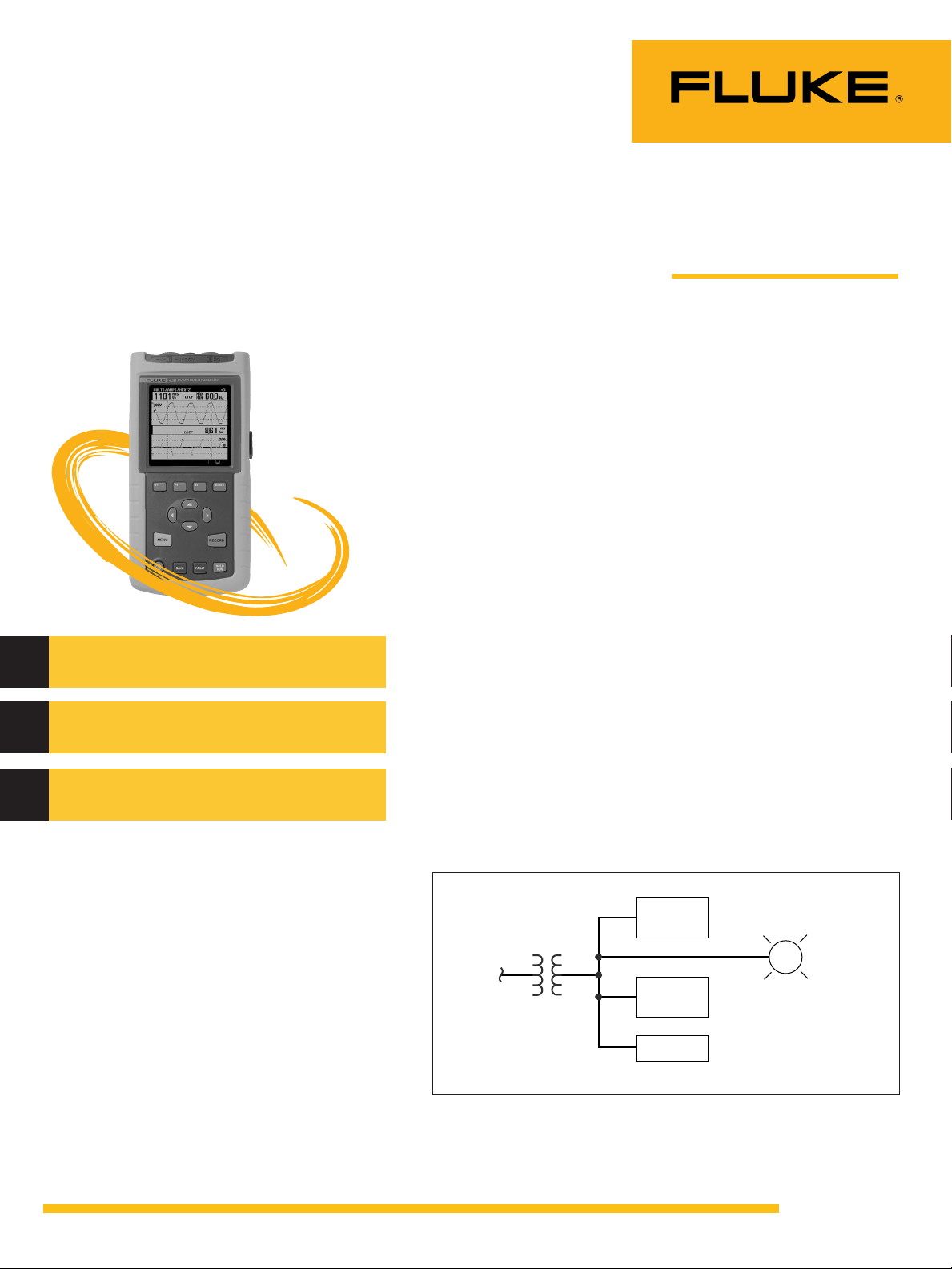
itself. The engineer’s investigation showed that three facilities
(a barbershop, a small café and
an automotive machine shop)
shared the transformer secondary that supplied power to the
traffic light. See Fig. 1.
One of the keys to troubleshooting a problem is determining what changed just prior
to the appearance of the problem. Visits to the barbershop
and café didn’t reveal anything
meaningful. The machine shop,
however, had a different story.
The shop had just installed a
new brake lathe they were
using to resurface brake drums
and rotors for cars and trucks.
The lathe was equipped with a
dc motor powered by a dc
adjustable speed drive.
Machine
Shop
Traffic
Light
Utility
Barber
Shop
Café
Fig. 1 One-line diagram showing power supplied to the traffic light
Operator: Electric utility engineer
Measuring tools: Fluke 43B Power
Quality Analyzer
Features used: Voltage, transient
capture
Power
Quality
Case
Study
Page 2
Fluke.Keeping your world
up and running.
Fluke Corporation
PO Box 9090, Everett, WA USA 98206
Fluke Europe B.V.
PO Box 1186, 5602 BD
Eindhoven, The Netherlands
For more information call:
In the U.S.A. (800) 443-5853 or
Fax (425) 446-5116
In Europe/M-East/Africa (31 40) 2 675 200 or
Fax (31 40) 2 675 222
In Canada (800)-36-FLU K E or
Fax (905) 890-6866
From other countries +1 (425) 446-5500 or
Fax +1 (425) 446-5116
Web access: http://www.fluke.com/
©2003 Fluke Corporation. All rights reserved.
Printed in U.S.A. 8/2003 2103520 A-ENG- N Rev A
Theory and analysis
Machine tool applications need
high torque at low speeds, and
dc motor/drive configurations
serve this need well. Thus,
machine tools commonly have
dc motors and drives. The input
rectifier circuit in a dc drive is
designed to provide variable
amounts of current to meet the
torque and speed requirements
of the motor. A commonly used
circuit configuration uses silicon
controlled rectifiers (SCRs) to
provide the variable current.
The SCR c ircuit produces
commutating spikes as one
rectifier is turned off before the
next rectifier is turned on. In
this case, the spikes generated
when the lathe was operating
were large enough to disrupt
the traffic light.
Solution
The engineer ordered a new
transformer and separate feeder
connection for the traffic light.
This new configuration
provided enough isolation to
keep things running normally.
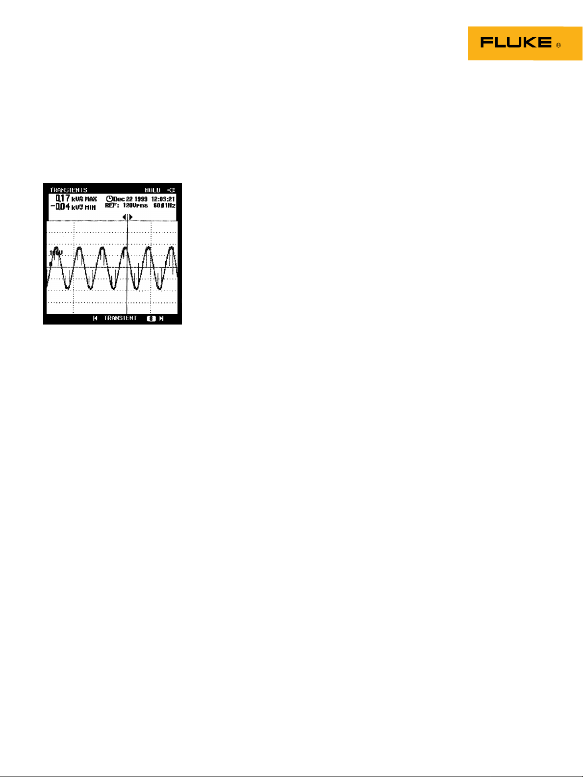
Measurements
The engineer connected his
43B to the machine shop’s
service entrance, line-to-line
with “Transient Capture” mode
activated. The 43B recorded
large voltage spikes whenever
the lathe was operating. See
Fig. 2.
Fig. 2 Voltage spikes from a dc adjustable
speed drive
2 Fluke Corporation Power Quality Case Study: Malfunctioning traffic light
 Loading...