

Page 1

33X
ClampMeters
Calibration Information
Introduction
XWWarning
To avoid electric shock or injury, do not perform the performance tests or
calibration procedures unless you are qualified to do so.
The information provided in this manual is for the use of qualified personnel
only.
The 33X Calibration Information provides the information necessary to verify the performance and adjust
the calibration of the Fluke 333, 334, 335, 336, and 337 ClampMeters, hereafter known as the Meter(s).
®
The following information is included in this document:
• Safety Information and International Electrical Symbols
• Specifications
• Replacing the Batteries
• Cleaning
• Performance Tests
• Calibration Adjustment
• User-Replaceable Parts and Accessories
• Warranty Statement
See the 33x Instruction Cards for complete operating instructions.
Contact Information
To contact Fluke, call:
1-888-99-FLUKE (1-888-993-5853) in USA
1-800-36-FLUKE (1-800-363-5853) in Canada
+31 402-675-200 in Europe
+81-3-3434-0181 Japan
+65-738-5655 Singapore
+1-425-446-5500 in other countries
For additional information about Fluke, its products, and services, visit Fluke’s web site at:
www.fluke.com
To register this product, go to register.fluke.com
PN 1618765 June 2001 Rev. 3, 4/06
© 2001-2006 Fluke Corporation. All rights reserved. Printed in U.S.A.
1
Page 2

33x
Calibration Information
Safety Information
XWWarnings and Precautions
To avoid possible electric shock or personal injury, and to avoid possible damage to the Meter
or the equipment under test, adhere to the following practices:
• Avoid working alone so assistance can be rendered.
• Never use the Meter on a circuit with voltages higher than 600 V or a frequency
higher than 400 Hz fundamental. The meter may be damaged.
• Do not use the Meter or test leads if they look damaged.
• Use extreme caution when working around bare conductors or bus bars. Contact
with the conductor could result in electric shock.
• Read the instruction card and safety sheet before use and follow all safety instructions.
• Use the Meter only as specified in the instruction card; otherwise, the Meter's safety
features may be impaired.
• Use caution when working with voltages above 60 V dc or 30 V ac. Such voltages
pose a shock hazard.
• Before using the Meter, inspect the case. Do not use the Meter if it is damaged. Look for
cracks or missing plastic. Pay particular attention to the insulation around the connectors.
• Verify the Meter’s operation by measuring a known voltage. Do not use the Meter if it
operates abnormally. Protection may be impaired. When in doubt, have the Meter serviced.
• Do not apply more than the rated current or voltage, as marked on the Meter.
• Use the proper terminals, function, and range for your measurements.
• Do not operate the Meter with the case (or part of the case) removed.
• When servicing the Meter, use only specified replacement parts.
International Electrical Symbols
The following international symbols appear in this document and on the Meter.
Y
W
T
M
)
P
J
F
B
;
N10140
s
~
Risk of electric shock
Risk of danger. Important Information. See manual.
Equipment protected by double or reinforced Insulation
Battery
Complies with U.S. and Canadian standards: UL61010B-1; CSA C22.2 No.1010.1-92
and amendment 2. Also complies with European standard EN 61010-2-032-04.
Conforms to EU directives
Earth
DC measurement
AC measurement
Conforms to relevant Australian standards
Inspected and licensed by TÜV Product Services
Do not dispose of this product as unsorted municipal waste. Contact Fluke or a qualified
recycler for disposal.
2
Page 3

ClampMeters
Specifications
Specifications
*These specifications apply
@ 23 °C ± 5 °C, in relative
humidity of 0 - 90%
?
(50 Hz/60 Hz)
Inrush Current Integration
Range 0 - 400.00 A 0 - 600.0 A 0 - 999.9 A
Accuracy 2 % ± 5 counts (50/60 Hz) 2 % ± 5 counts (10 - 100 Hz)
Crest
Factor
add 2% for
CF > 2
AC
response
Time
Range NA NA NA 0 - 600.0 A 0 - 999.9 A A
Accuracy NA NA NA 2 % ± 5 counts
Range 0 - 600.00 V K
Accuracy 1 % ± 5 counts
333
NA NA 2.4 @ 500 A
Avg Rms
NA 100 ms
334
2.0 @ 600 A
50/60 Hz
335
3 @ 500 A
2.5 @ 600 A
336
6 % ± 5 counts (10 - 400 Hz)
3 @ 500 A
2.5 @ 600 A
1.42 @ 1000 A
1 % ± 5 counts (20 - 100 Hz)
6 % ± 5 counts (100 - 400 Hz)
337
Range 0 - 600.0 V L
Accuracy 1 % ± 5 counts
e
Continuity R ≤ 30 Ω
Trigger Level:
10-100 Hz ≥ 5 A
5-10 Hz,
100-400 Hz > 10 A
Storage
Temperature
Operating
Temperature
Altitude 2500 m
EMC- instrument unspecified for use in EMC field ≥ 0.5 V/m
CAT III 600 V, Pollution Degree II:
CAT III equipment is designed to protect against transients in equipment in fixed-equipment installations, such as
distribution panels, feeders and short branch circuits, and lighting systems in large buildings.
Range 0 - 600.0 Ω 0 - 600.0 Ω
600 - 6000 Ω
Accuracy 1.5 % ± 5 counts
Range NA NA NA NA 5.0 - 400.0 Hz Hz-Amps Only
Accuracy NA NA NA NA 0.5 % ± 5 counts
-40 °C to 60 °C
-10 °C to 50 °C
*< 18 °C,> 28 °C add 0.1 x (specified accuracy)/°C
3
Page 4
33x
Calibration Information
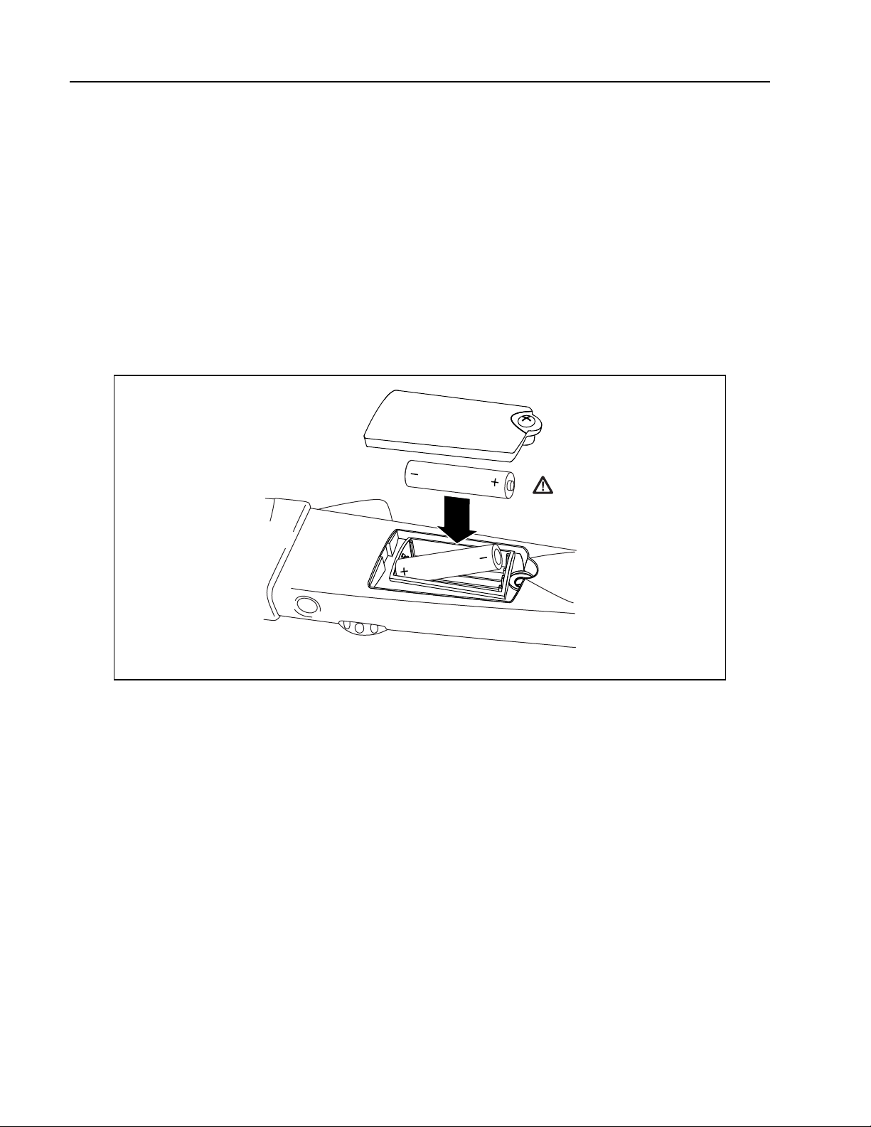
Replacing the Batteries
To avoid false readings, that could lead to possible electric shock or personal
injury, replace the batteries as soon as the low battery indicator (B) appears.
Disconnect the test leads before replacing the batteries.
To replace the batteries (refer to Figure 1):
XWWarning
1. Turn the rotary switch to
OFF and remove the test leads from the terminals.
2. Loosen the battery compartment door screw, and remove the door from the case bottom.
3. Remove the batteries.
4. Replace the batteries with 2 new AA batteries.
5. Reattach the battery compartment door to the case bottom and tighten the screw.
Figure 1. Replacing the Batteries
Cleaning
XW Warning
To avoid electrical shock, remove any input signals before cleaning.
WCaution
To avoid damaging the Meter, do not use aromatic hydrocarbons or chlorinated
solvents for cleaning. These solutions will react with the plastics used in the
instruments.
Clean the instrument case with a damp cloth and mild detergent.
4
adc02f.eps
Page 5
static awareness
A Message From
Fluke Corporation
Some semiconductors and custom IC's can be
damaged by electrostatic discharge during
handling. This notice explains how you can
minimize the chances of destroying such devices
by:
1. Knowing that there is a problem.
2. Learning the guidelines for handling them.
3. Using the procedures, packaging, and
bench techniques that are recommended.
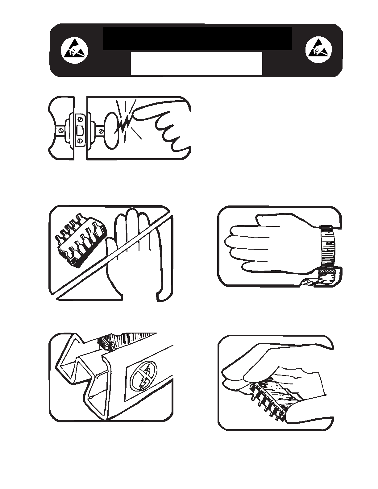
The following practices should be followed to minimize damage to S.S. (static sensitive) devices.
1. MINIMIZE HANDLING
2. KEEP PARTS IN ORIGINAL CONTAINERS
UNTIL READY FOR USE.
3. DISCHARGE PERSONAL STATIC BEFORE
HANDLING DEVICES. USE A HIGH RESIS TANCE GROUNDING WRIST STRAP.
4. HANDLE S.S. DEVICES BY THE BODY.
Page 6
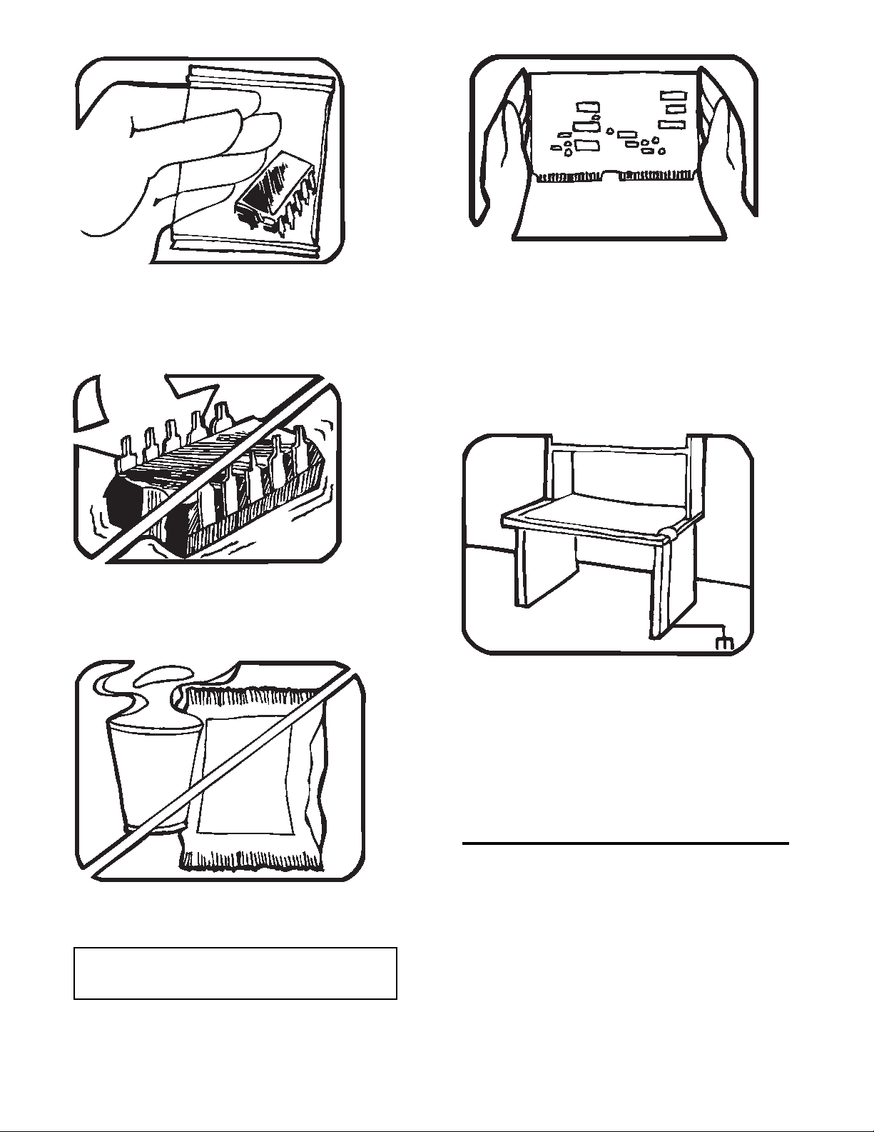
5. USE STATIC SHIELDING CONTAINERS FOR
HANDLING AND TRANSPORT.
6. DO NOT SLIDE S.S. DEVICES OVER
ANY SURFACE.
8. WHEN REMOVING PLUG-IN ASSEMBLIES
HANDLE ONLY BY NON-CONDUCTIVE
EDGES AND NEVER TOUCH OPEN EDGE
CONNECTOR EXCEPT AT STATIC-FREE
WORK STATION. PLACING SHORTING
STRIPS ON EDGE CONNECTOR HELPS
PROTECT INSTALLED S.S. DEVICES.
9. HANDLE S.S. DEVICES ONLY AT A
STATIC-FREE WORK STATION.
7. AVOID PLASTIC,VINYL AND STYROFOAM
IN WORK AREA.
PORTIONS REPRINTED
WITH PERMISSION FROM TEKTRONIX INC.
AND GERNER DYNAMICS, POMONA DIV.
Dow Chemical
10. ONLY ANTI-STATIC TYPE SOLDER SUCKERS SHOULD BE USED.
11. ONLY GROUNDED-TIP SOLDERING
IRONS SHOULD BE USED.
Page 7

ClampMeters
Performance Tests
Performance Tests
XWWarning
To avoid electric shock, do not perform the performance test procedures unless
the Meter is fully assembled.
The following performance tests verify the complete operation of the Meter and check the accuracy of
each meter function against the Meter’s specifications. If the Meter fails any part of the test, calibration
adjustment and/or repair is indicated.
In the performance tests, the Meter is referred to as the unit under test (UUT).
Table 1. Required Equipment
Equipment Recommended Model
AC Calibrator Fluke 5520A
Digital Multimeter (DMM) Any Fluke model
50-Turn Current Coil Fluke 5500A/Coil
Testing the Display
For models 334 - 337, test the display by turning the Meter on while holding down the INRUSH button.
Check all segments for clarity and contrast. The 333 is not equipped with this feature. Refer to Figure 2.
Figure 2. Testing the Display (337 is shown)
5
adc01f.eps
Page 8

33x
Calibration Information
Backlight Test
The 334, 335, 336, and 337 Clampmeters are equipped with a display backlight. To test the backlight,
press b. The backlight will come on and the unit will beep. To turn off the backlight, press b a second
time. Refer to Figure 3.
Figure 3. Testing the Backlight
Keypad Test
To test the keypad, turn the Meter on and push each button separately. Each button push will cause the
Meter to beep.
Preparing for the Performance Test
XWWarning
To avoid possible electric shock or personal injury:
• Do not perform the following procedures unless qualified to do so. Some
procedures involve the use of high voltages.
• Before handling the test connections and in between tests, make sure the
calibrator is in standby mode (STBY).
To prepare for the performance test:
1. Make sure that you have the required equipment, see Table 1.
2. Warm up the calibrator as required by its specifications.
3. Allow the temperature of the UUT to stabilize at room temperature ( 23 °C ± 5 °C [73 °F ± 9 °F] ).
adc03f.eps
6
Page 9

ClampMeters
Performance Tests
Performance Test Procedure
To test each of the Meter's functions and operating ranges, do the following:
1. Connect the source to the Meter's VΩ and COM input jacks.
2. Referring to Table 2, put the Meter in the desired function and range for each test.
3. Apply the indicated output from the source.
4. When using the amp function on the 5520A, make sure LCOMP on the 5520A is ON.
5. The reading on the Meter display should be within the low and high limits shown in the table.
6. Repeat steps 1-4 for each function and range in Table 2.
If the Meter fails to perform within the low-high range indicated for each test in Table 2, the Meter needs
to be calibrated and adjusted, or requires some repair.
Figure 4. 33x Amps/Hz Verification Setup
7
adc07f.eps
Page 10

33x
Calibration Information
Table 2. Performance Tests 333, 334, 335
Test
(Switch Position)
20 V 50 Hz 19.3 V AC 20.7 V AC K
AC Volts
L
DC Volts
R
Continuity
Ohms
?
Amps AC
*INRUSH **5 A 60 Hz 4.4 A AC 5.6 A AC
600 V 50 Hz 593.5 V AC 606.5 V AC
20 V 19.3 V DC 20.7 V DC
-20 V -20.7 V DC -19.3 V DC
600 V 593.5 V DC 606.5 V DC
-600 V -606.5 V DC -593.5 V DC
25 Ω Beeper On
600 Ω 590.5 Ω 609.5 Ω e
6 KΩ (334, 335) 5905 Ω 6095 Ω
.4 A 50 Hz 19.1 A AC 20.9 A AC
4 A 50 Hz 195.5 A AC 204.5 A AC
10 A 50 Hz (333) 391.5 408.5
12 A 50 Hz (334, 335) 587.5 A AC 612.5 A AC
Meter Response
5520A Output Lower Limit Upper Limit
*The “INRUSH” button must be pressed after current is applied to the 50-turn coil.
**Display should bar (- - - -), then show reading with inrush light on (334, 335)
8
Page 11

ClampMeters
Table 2. Performance Tests 336, 337 (cont.)
Performance Tests
Test
(Switch Position)
K
AC Volts
L
DC Volts
R
Continuity
Ohms
?
Amps AC
Meter Response
5520A Output Lower Limit Upper Limit
20 V 50 Hz 19.3 V AC 20.7 V AC
600 V 50 Hz 593.5 V AC 606.5 V AC
600 V 400 Hz 563.5 V AC 636.5 V AC
600 V 400 Hz 563.5 V AC 636.5 V AC Min/Max (337)
20 V 400 Hz Reading does not change
20 V 19.3 V DC 20.7 V DC
-20 V -20.7 V DC -19.3 V DC
600 V 593.5 V DC 606.5 V DC
-600 V -606.5 V DC -593.5 V DC
25 Ω Beeper On
600 Ω 590.5 Ω 609.5 Ω e
6 KΩ 5905 Ω 6095 Ω
.4 A 50 Hz 19.1 A AC 20.9 A AC
4 A 50 Hz 195.5 A AC 204.5 A AC
10 A 50 Hz 187.5 A AC 212.5 A AC
12 A 50 Hz 587.5 A AC 612.5 A AC
18 A 50 Hz (337 only) 881.5 A AC 918.5 A AC
*INRUSH **5 A 60 Hz 4.4 A AC 5.6 A AC
A
DC Amps
*The “INRUSH” button must be pressed after current is applied to the 50-turn coil.
**Display should bar (- - - -), then show reading with inrush light on (334, 335)
0.0 A after button push -0.5 A DC 0.5 A DC
.4 A 19.1 A DC 20.9 A DC
-.4 A -20.9 A DC -19.1 A DC
12 A 587.5 A DC 612.5 A DC
-12 A -612.5 A DC -587.5 A DC
18 A (337) 881.5 A DC 918.5 A DC
-18 A (337) -918.5 A DC -881.5 A DC
5 A 10 Hz 9.4 Hz 10.6 Hz Frequency (337)
10 A 300 Hz 298.0 Hz 302.0 Hz
9
Page 12

33x
Calibration Information
Calibration Adjustment 333, 334, & 335
Use the following steps to adjust the calibration of the 333, 334, and 335 meters (refer to Figure 5):
1. Remove the 2 screw on the bottom of the Meter.
2. Lift off the top case.
3. Apply 600.0 V 50 Hz.
4. Adjust R12 until display reads within 1.0 V.
5. Apply 200.0 A 50 Hz (remove 600 Vac).
6. Adjust R15 until the display reads within 0.5 A.
7. Replace the top case.
8. Replace the case screws.
9. Verify the calibration by going through the performance test procedures.
10
Page 13

ClampMeters
Performance Tests
Figure 5. Calibration Adjustment Points (333-335)
adc05f.eps
11
Page 14

33x
Calibration Information
Calibration Adjustment 336 & 337
Use the following steps to adjust the calibration of the 336 and 337 meters (refer to Figures 5 and 6):
1. Remove the 2 screw on the bottom of the Meter.
2. Lift off the top case.
3. Apply 600.0 V 50 Hz.
4. Adjust R12 until the UUT display reads within 1.0 V.
5. Remove 600.0 V.
6. Change to the A DC Function.
7. Adjust R60 until the display reads within 2.0 A of 0 A DC.
8. Change to the A AC function.
9. Apply 100.0 A 50 Hz.
10. Note measurement with wire at top and bottom of jaw opening.
11. Adjust R9 until this difference is within 1.0 A.
12. Replace top case.
13. Open battery door and remove the batteries.
14. Apply 2.7 V to 3.2 V to battery terminals.
15. Change to AAC function.
16. Apply 600.0 A 50 Hz.
17. Adjust R61 until the display reads within 1.0 A.
18. Replace the batteries.
19. Verify the calibration by going through the Performance Test procedures.
12
Page 15

ClampMeters
Performance Tests
Figure 6. Calibration Adjustment Points 336-337
adc06f.eps
13
Page 16

33x
Calibration Information
Figure 7. Calibration Adjustment (336-337)
adc04f.eps
14
Page 17

ClampMeters
User-Replaceable Parts and Accessories
User-Replaceable Parts and Accessories
Item # Description Part No Qty
A
B
C
D
E
F
G
H
I
J
K
L
Not Shown
Not Shown
Not Shown
Not Shown
* WTo ensure safety, use exact replacement only.
** Fluke accessories are available from your authorized Fluke distributor.
Knob 1611630 1
Case Top (Model 333)
Case Top (Model 334)
Case Top (Model 335)
Case Top (Model 336)
Case Top (Model 337)
Button, Backlight (334-337) 1611585 1
Button, Hold 1611572 1
Screw, case (small) 1611682 1
Battery,1.5V,0-150MA, AA Alkaline 376756 2
Battery Door 1611653 1
Screw, Battery Door 1611694 1
Screw, case (large) 1611666 1
Input Recepticle Housing 1611648 1
Keypad (334,335)
Keypad (336)
Keypad (337)
TL75 Test Lead Set** 855705 1
Softcase 1587541 1
333, 334, 335, 336, and 337 Safety Sheet 1561546 1
333,334, and 335 Instruction Card
336 and 337 Instruction Card
Calibration Manual 1618765 1
1611439
1611442
1611456
1611474
1611488
1611597
1611611
1611627
1549865
1549876
adc08f.eps
1
1
1
1
1
1
1
1
1
1
Figure 8. User-Replaceable Parts and Accessories
15
Page 18

33x
Calibration Information
LIMITED WARRANTY AND LIMITATION OF LIABILITY
This Fluke product is warranted to be free from defects in material and workmanship under normal use and service. The warranty period is
three years and begins on the date of shipment. Parts, product repairs, and services are warranted for 90 days. This warranty extends only
to the original buyer or end-user customer of a Fluke authorized reseller, and does not apply to fuses, disposable batteries, or to any
product which, in Fluke's opinion, has been misused, altered, neglected, contaminated, or damaged by accident or abnormal conditions of
operation or handling. Fluke warrants that software will operate substantially in accordance with its functional specifications for 90 days
and that it has been properly recorded on non-defective media. Fluke does not warrant that software will be error free or operate without
interruption.
Fluke authorized resellers shall extend this warranty on new and unused products to end-user customers only but have no authority to
extend a greater or different warranty on behalf of Fluke. Warranty support is available only if product is purchased through a Fluke
authorized sales outlet or Buyer has paid the applicable international price. Fluke reserves the right to invoice Buyer for importation costs
of repair/replacement parts when product purchased in one country is submitted for repair in another country.
Fluke's warranty obligation is limited, at Fluke's option, to refund of the purchase price, free of charge repair, or replacement of a defective
product which is returned to a Fluke authorized service center within the warranty period.
To obtain warranty service, contact your nearest Fluke authorized service center to obtain return authorization information, then send the
product to that service center, with a description of the difficulty, postage and insurance prepaid (FOB Destination). Fluke assumes no risk
for damage in transit. Following warranty repair, the product will be returned to Buyer, transportation prepaid (FOB Destination). If Fluke
determines that failure was caused by neglect, misuse, contamination, alteration, accident, or abnormal condition of operation or handling,
including overvoltage failures caused by use outside the product’s specified rating, or normal wear and tear of mechanical components,
Fluke will provide an estimate of repair costs and obtain authorization before commencing the work. Following repair, the product will be
returned to the Buyer transportation prepaid and the Buyer will be billed for the repair and return transportation charges (FOB Shipping
Point).
THIS WARRANTY IS BUYER'S SOLE AND EXCLUSIVE REMEDY AND IS IN LIEU OF ALL OTHER WARRANTIES, EXPRESS OR
IMPLIED, INCLUDING BUT NOT LIMITED TO ANY IMPLIED WARRANTY OF MERCHANTABILITY OR FITNESS FOR A PARTICULAR
PURPOSE. FLUKE SHALL NOT BE LIABLE FOR ANY SPECIAL, INDIRECT, INCIDENTAL OR CONSEQUENTIAL DAMAGES OR
LOSSES, INCLUDING LOSS OF DATA, ARISING FROM ANY CAUSE OR THEORY.
Since some countries or states do not allow limitation of the term of an implied warranty, or exclusion or limitation of incidental or
consequential damages, the limitations and exclusions of this warranty may not apply to every buyer. If any provision of this Warranty is
held invalid or unenforceable by a court or other decision-maker of competent jurisdiction, such holding will not affect the validity or
enforceability of any other provision.
Fluke Corporation
P.O. Box 9090
Everett, WA 98206-9090
U.S.A.
Fluke Europe B.V.
P.O. Box 1186
5602 BD Eindhoven
The Netherlands
11/99
To register this product, go to register.fluke.com
16
 Loading...