

Page 1

Nuclear Associates 30-471
VeriDose
®
Solid-State Diode Detectors
February 2005
Manual No. 30-471-8000-1 Rev. 2
©2004, 2005 Fluke Corporation, All rights reserved. Printed in U.S.A.
All product names are trademarks of their respective companies
Operators Manual
Page 2

Fluke Biomedical
Radiation Management Services
6045 Cochran Road
Cleveland, Ohio 44139
440.498.2564
120 Andrews Road
Hicksville, New York 11801
516.870.0100
www.flukebiomedical.com/rms
Page 3

Table Of Contents
Section 1: General Information................................................................................... 1-1
1.1 Introduction .................................................................................................. 1-1
1.2 Specifications............................................................................................... 1-2
1.3 Accessories ................................................................................................. 1-2
1.4 Calibration Technique.................................................................................. 1-2
1.5 Receiving Inspection.................................................................................... 1-3
1.6 Storage ........................................................................................................ 1-3
1.7 Routine Cleaning ......................................................................................... 1-3
1.8 Procedures, Warnings, and Cautions .......................................................... 1-3
Section 2: Operation.................................................................................................... 2-1
2.1 Operation ..................................................................................................... 2-1
2.2 Phonton Detectors ....................................................................................... 2-2
2.3 Electron Detectors ....................................................................................... 2-6
Section 3: Theory of Operation................................................................................... 3-1
3.1 Theory of Operation..................................................................................... 3-1
Section 4: Maintenance, Calibration and Troubleshooting...................................... 4-1
4.1 Maintenance ................................................................................................ 4-1
4.2 Calibration.................................................................................................... 4-1
4.3 Troubleshooting ........................................................................................... 4-1
Appendix A Drawings.....................................................................................................A-1
A.1 Drawings...................................................................................................... A-1
Appendix B: Radiation Damage ..................................................................................... B-1
B.1 Radiation Damage ....................................................................................... B-1
i
Page 4

(Blank Page)
Page 5
General Information
Introduction
1
Section 1
General Information
This device is intended for use only by persons who
have been trained in the proper interpretation of its
readings and in the appropriate safety procedures
to be followed in the presence of radiation.
These detectors are not designed, nor are they
recommended for use in primary calibration.
WARNING
CAUTION
1.1 Introduction
The VeriDose Detectors, Models 30-471 through 30-475 and 30-471-8000 through 30-475-8000, are ntype diodes utilizing a p-n junction and are designed for use as radiation detection devices. These diodes
are encased within a FDA approved polystyrene material. A low noise coaxial cable is used to connect
the diode to an electrometer. In this configuration, these diodes provide enhanced sensitivity,
instantaneous response time and are very rugged. With advantages such as large signal and fast
response, these diodes are ideal for relative measurements in areas of steep dose gradients and relative
absorbed dose in electron beam fields.
The Solid State Radiation Detector Diodes are constructed using a "parallel plate" geometry with planar
electrodes opposing each other at a given spacing. This configuration has many advantages over the
commonly used coaxial cylindrical geometry which have the electrodes being inner and outer shells.
The most obvious advantage is its superior construction and ease of orientation to the radiation beam.
Unlike the cylindrical style diodes where the alignment of the diode's sensitive volume is critical in
relationship to the radiation beam, the sensitive volume of the VeriDose Diode is the entire diode, which
allows for a less stringent alignment to the radiation beam. The hemispherical shape also allows for
easier attachment to the patient. The ideal orientation of the diode within the radiation beam is to have the
beam perpendicular to the diode's horizontal axis. As long as the beam is wider than the diode, full
collection of all ionization produced will occur regardless of the exact position in the active region.
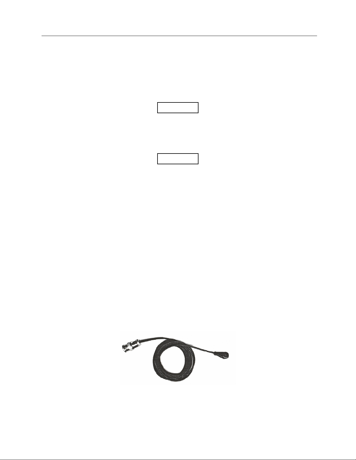
However, for ease of alignment within a radiation
beam a raised X has been placed on top of the diode.
Figure 1-1. General View of the VeriDose Diode
1-1
Page 6
Nuclear Associates 30-471
Operators Manual
1.2 Specifications
Sensitivity:
Diameter:
Cable Length:
Output Polarity:
Weight:
Sensitive Volume:
Linearity:
Reproducibility:
Temp. Dependence:
Angular Dependence:
Rad Damage @10 kGy:
Operating Temp.:
Relative Humidity:
1.5 nC/cGy
Phonton: 12 mm Diameter
Electron: 11 mm Diameter
2 meters
pos/neg
42 gm
0.25 mm
2.25%
0.2%
< 0.5% /°C
Refer to the graphs on page 18 - 25
< 15%
10° C to 40° C (50° F to 104° F)
5 to 95%, non-condensing
3
1.3 Accessories
Part Number Description
VeriDose QC
(37-705-5000)
Diode Detector Holder
(37-492-1000)
Calibration Fixture
(37-705-4000)
Extension Cable
(88-490)
Dual purpose acrylic phantom, daily QA, flatness/symmetry & depth
dose
Acrylic, 5-slot, wall mount
Acrylic, 5-slot
10 meter low noise coaxial cable
1.4 Calibration Technique
The VeriDose diode detectors are part of a dose monitoring system. In order to obtain accurate results,
the detectors must be used with a suitable patient dose-monitoring device. The VeriDose V, available
from Fluke Biomedical, Radiation Management Services is a 5-channel dose monitor designed
specifically for use with this type of detector. A calibration fixture is available to hold the detectors in a
fixed, reproducible geometry during the calibration process. For optimum performance, the detector must
be used within the energy range for which it was designed. Since the detectors are designed with an
internal build-up cap, additional build-up is not required.
It is recommended that the system be calibrated under clinical conditions at which the detectors will be
normally used. Since the calibration process will associate a particular detector to a specific channel on
the dose-monitoring device, it is necessary to exercise caution when reconnecting the detectors for
subsequent measurements. Each detector must be connected to the channel to which it was calibrated.
1-2
Page 7

General Information
Calibration Technique
The detectors must be positioned in close proximity to the isocenter using the optional calibration fixture
or an alternative method to obtain a uniform dose. A typical exposure of 100-200 cGy at a dose rate of
100-300 cGy/min is adequate for calibration. Refer to the calibration section of the appropriate operator’s
manual for the dose-monitoring device for a complete description of the adjustment procedure. Upon
completion of the calibration process, several additional exposures should be made in the normal
measurement mode of the dose monitor in order to verify the calibration.
1
1.5 Receiving Inspection
Upon receipt of the diodes:
1. Inspect the carton(s) and contents for damage. If damage is evident, file a claim with the carrier and
contact Fluke Biomedical, Radiation Management Services at 440.248.9300.
2. Remove the contents from the packing material and visually inspect the unit for damage.
3. Verify that all items on the packing list have been received and are in good condition.
1.6 Storage
If the diodes are to be stored prior to use, pack them in the original container, if possible, and store in an
environment free of corrosive materials, fluctuations in temperature and humidity, and vibration and
shock.
1.7 Routine Cleaning
The VeriDose diodes should be kept clean and free from dirt and contamination. The unit may be
cleaned by wiping with a damp cloth, using any commercially available cleaning or decontaminating
agent.
1.8 Procedures, Warnings, and Cautions
The equipment described in this manual is intended to be used for the detection and measurement of
ionizing radiation. It should be used only by persons who have been trained in the proper interpretation of
its readings and the appropriate safety procedures to be followed in the presence of radiation.
Although the equipment described in this manual is designed and manufactured in compliance with all
applicable safety standards, certain hazards are inherent in the use of electronic and radiometric
equipment.
WARNINGS and CAUTIONS are presented throughout this document to alert the user to potentially
hazardous situations. A WARNING is a precautionary message preceding an operation which has the
potential to cause personal injury or death. A CAUTION is a precautionary message preceding an
operation which has the potential to cause permanent damage to the equipment and/or loss of data.
Failure to comply with WARNINGS and CAUTIONS is at the user's own risk and is sufficient cause to
terminate the warranty agreement between Fluke Biomedical and the customer.
Adequate warnings are included in this manual and on the product itself to cover hazards that may be
encountered in normal use and servicing of this equipment. No other procedures are warranted by Fluke
Biomedical. It shall be the owner's or user's responsibility to see to it that the procedures described here
are meticulously followed, and especially that WARNINGS and CAUTIONS are heeded. Failure on the
part of the owner or user in any way to follow the prescribed procedures shall absolve Fluke Biomedical
and its agents from any resulting liability.
1-3
Page 8

Nuclear Associates 30-471
Operators Manual
Indicated battery and other operational tests must be performed prior to each use to assure that the
instrument is functioning properly. If applicable, failure to conduct periodic performance tests in
accordance with ANSI N323-l978 (R1983) Radiation Detection Instrumentation Test and Calibration,
paragraphs 4.6 and 5.4. and to keep records thereof in accordance with paragraph 4.5 of the same
standard, could result in erroneous readings or potential danger. ANSI N323-1978 becomes, by this
reference, a part of this operating procedure.
1-4
Page 9

Operation
Operation
2
Section 2
Operation
2.1 Operation
The solid-state detectors are p-n junction style diodes that are operated with zero applied bias voltage.
This mode of operation is known as the photovoltaic mode. In this mode the diode becomes a selfgenerating device, not requiring a power supply. When the diode's sensitive region is introduced to
radiation, it produces a current output. Based on the internal construction of the detector, this output
current is either positive or negative.
Within these detectors a silicon conductor chip is utilized. By using this chip, it minimizes the detectors
leakage current. Since the leakage current has been reduced and due to the detectors great resistance, a
stable output is achieved. This output is exceptionally linear throughout the specified range of the
detector. With radiation fields that cover the specified range of the appropriate diode detector, the
detector's reproducibility is better than 0.2%. This output remains constant as long as the dose and diode
position remain constant. Changes in this output only become noticeable when the source to detector
distance (SDD) is altered.
The isotropic characteristics of these detectors allows for measurements to be made with little
consideration of the detectors orientation within the radiation field. The reason for this is that the
detector's sensitive area always faces the radiation field regardless of the detectors position. This
characteristic allows for an excellent geometric response. However, ideally the detector should be placed
in the radiation field so that the field totally encompasses the detector. A raised cross hair has been
placed on top of the detector to allow for ease of alignment. They can be applied to the patient with tape,
and the rugged waterproof housing allows ease of cleaning with no degradation to the detector.
The sensitivity variation with temperature (SVWT) coefficient which is taken into account for thermal
transfer from the patient is < 0.5% per degree Celsius. The semiconductor material within the detector is
influenced by temperature. The effect of temperature is to introduce or remove more thermoenergy to the
system. More energy bounces more charge carriers out of the centers, and thus increases the signals.
The rate of change in sensitivity with temperature depends on the number of generation-recombination
centers.
2-1
Page 10

Nuclear Associates 30-471
y
Operators Manual
2.2 Photon Detectors
These detectors are used in the measurement of radiation in the range of 1 MV to 25 MV. They are
available with a negative or positive output. They have been color coded for ease of identification.
Following is a list of the detectors, polarity, color codes, and range.
Model Number Range Polarity Color
30-471 1-4 MV Photon Positive Blue
30-471-8000 1-4 MV Photon Negative Blue
30-472 5-11 MV Photon Positive Yellow
30-472-8000 5-11 MV Photon Negative Yellow
30-473 12-17 MV Photon Positive Red
30-473-8000 12-17 MV Photon Negative Red
30-474 18-25 MV Photon Positive Green
30-474-8000 18-25 MV Photon Negative Green
30-475 5-25 MeV Electron Positive Gray
30-475-8000 5-25 MeV Electron Negative Gray
Build-up shields are utilized in their design to provide equilibrium and filtering of low energy radiation.
These build-up shields also increase the detector's stability along with increasing the sensitivity in their
respective ranges. The output of a typical detector is 1.2 nano coulombs/RAD (1.2 nC/cGy).
The semiconducting material in these diodes is planar and the diodes as a whole is hemispherical in
shape, thus they have a preferred direction. Following are typical angular dependence of these photon
detectors.
Angular Dependence
1-4 MV Diodes
The following figures show the results for incident angles rotation along the diode cable axis and along
the axis perpendicular to diode cable axis. For angle deflections less than 50 degrees from the diodes
preferred direction, 180 degrees, the diode output changed by less than 1%.
Diode (type 471 [1–4 MV rated]) output vs. incident angle;
symmetric setup in 6 MV photons
Diode output (normalized to 180°)
angle (degree with 180 being vertical)
Gantr
2-2
Page 11

Operation
y
Photon Detectors
Diode output (normalized to 180°)
Diode (type 471 [1–4 MV rated]) output vs. incident angle;
asymmetric setup cable faces collimator when at 90 degrees
angle (degree with 180 being vertical)
Gantr
2
5–11 MV Diodes
Similar results are shown in the following figures for 5-11 MV diodes, although the output changes by less
than 1% for a slightly smaller range of angles. That range being 35-40 degrees from 180 for both planes
of rotation.
Diode (type 472 [5–11 MV rated]) output vs. incident angle;
symmetric setup in 6 MV phontons
Diode output (normalized to 180°)
Gantry angle (degree with 180 being vertical)
2-3
Page 12

Nuclear Associates 30-471
y
Operators Manual
12-17 MV Diodes
Diode (type 472 [5–11 MV rated]) output vs. incident angle;
asymmetric setup in 6 MV photons
Diode output (normalized to 180°)
angle (degree with 180 being vertical)
Gantr
As seen in the following figures, the results are good for angle variations in the plane perpendicular to the
direction of the cable. Again, there is a small (less than 1%) variation extending to ± 30-35 degrees off
center. Along the plane that includes the cable there is a 3% - 4% variation over the same angular range.
Diode (type 473 [12–17 MV rated]) output vs. incident angle;
symmetric setup in 6 MV photons
Diode output (normalized to 180°)
Gantry angle (degree with 180 being vertical)
2-4
Page 13

Operation
Photon Detectors
Diode (type 473 [12–17 MV rated]) output vs. incident angle;
asymmetric setup cable faces collimator when at 90 degrees
Diode output (normalized to 180°)
Gantry angle (degree with 180 being vertical)
2
18–25 MV Diodes
As seen in the following figure, the results are good for angle variations in the plane perpendicular to the
direction of the cable.
Diode (type 474 [18–25 MV rated]) output vs. incident angle;
symmetric setup in 6 MV photons
Diode output (normalized to 180°)
Gantry angle (degree with 180 being vertical)
2-5
Page 14

Nuclear Associates 30-471
y
Operators Manual
2.3 Electron Detectors
These detectors are used in the measurement of radiation in the range of 5 MeV to 25 MeV. They are
available with a negative or positive output. They are color coded for ease of identification. Following is a
list of the detectors, polarity, color codes, and range.
Model Number Range Polarity Color
30-475 5-25 MeV Electron Positive Gray
30-475-8000 5-25 MeV Electron Negative Gray
The semiconducting material in these diodes is planar and the diode as a whole is hemispherical in
shape, thus they have a preferred direction. Following are typical graphs of the angular dependence of
these electron detectors.
The output of a typical detector is 1.00 nano coulombs/RAD (1.00 nC/cGy).
Angular Dependence
The electron diodes in a 20 MeV electron beam, shown in the following two figures have a I % change
after a 30 degrees deflection, in both planes from 180.
Diode output (normalized to 180°)
Diode (type 475 [electron diode]) output vs. incident angle;
asymmetric setup in 20 MeV electrons
angle (degree with 180 being vertical)
Gantr
2-6
Page 15

Operation
y
Electron Detectors
Diode output (normalized to 180°)
Diode (type 475 [electron diode]) output vs. incident angle;
symmetric setup in 20 MeV electrons
angle (degree with 180 being vertical)
Gantr
2
2-7
Page 16

(Blank Page)
Page 17

Theory Of Operation
Theory of Operation
3
Section 3
Theory of Operation
3.1 Theory of Operation
Semiconductors have been actively used as a solid medium for radiation monitoring since the 1960's.
Early versions of semiconductor detectors were referred to as crystal counters. Today they are known as
diode detectors or solid-state detectors.
The main advantage of using a semiconductor for a radiation detector is its ability to generate a large
number of information carriers for a given incident radiation event. The information carriers that we are
concerned with are the electron-hole pairs created by the impinging radiation through the detector. When
a charged particle passes through the semiconductor it generates electron-hole pairs along its path. The
amount of charge collected by this event is related to the energy loss of the charged particles passing
through the semiconductor.
It is the charge carriers’ interaction with the generator-recombination centers that cause variations with
dose rate. At low dose rates, electrons and holes recombine and are ejected from the centers at some
rate. As the dose rate becomes high, the center starts to become saturated by electrons or holes. The
carriers are then able to proceed farther then they were previously. Increasing the path length of the
carriers in effect increases the sensitivity of the detector.
By placing a detector, along with a farmer chamber, at different distances from a radiation source, the
determination of variation with dose rate can be accomplished. Any variations of the detector with respect
to the farmer chamber reflects that detector's variation with dose rate. It was determined that the farmer
chamber accurately recorded the relative change in dose with distance. Both sets of measurements were
normalized to 100 SSD. The following graphs show the results to the measurement made.
Diode (type 472 [5–11 MV phontons]) output farmer chamber
vs. SSD “Dose Rate Dependence”
Normalized reading (diode/farmer chamber)
SSD (cm)
3-1
Page 18

Nuclear Associates 30-471
p
Operators Manual
Diode (type 474 [18–25 MV phontons])
output farmer chamber vs. SSD
ut/farmer chamber (normalized to 100 SSD)
Diode out
SSD (cm)
Based on the characteristics of these detectors, they are used for specific applications such as exit dose
measurements, intracavitary measurements and also with radiation therapy. Given the quick response of
these detectors, they are very useful for verifying the patient’s dose delivered during therapy and also as
a safeguard against misadministered radiation treatments.
With various types of integral filters and build-up shields these detectors can measure radiation
exposures as low as 1 MeV and as high as 25 MV. They are also available with a negative or positive
polarity output. The various types of detectors have been color coded to identify them with a specific
energy range. This allows for ease of identification and avoidance of misuse. Following is a list of diodes
and their associated part numbers that are available.
Model Number Range Polarity Color
30-471 1-4 MV Phonton Positive Blue
30-471-8000 1-4 MV Phonton Negative Blue
30-472 5-11 MV Phonton Positive Yellow
30-472-8000 5-11 MV Phonton Negative Yellow
30-473 12-17 MV Phonton Positive Red
30-473-8000 12-17 MV Phonton Negative Red
30-474 18-25 MV Phonton Positive Green
30-474-8000 18-25 MV Phonton Negative Green
30-475 5-25 MeV Electron Positive Gray
30-475-8000 5-25 MeV Electron Negative Gray
3-2
Page 19

Maintenance, Calibration, and Trouble Shooting
Maintenance
Section 4
Maintenance, Calibration and Troubleshooting
4.1 Maintenance
Due to the rugged construction of these detectors, periodic maintenance is not required.
4.2 Calibration
Over time, the amount of exposures the detector is subject to may result in damage to the detector. The
effect these exposures have is a reduction in the detectors original response.
In light of this characteristic of these detectors, they provide a high degree of reproducibility in their
outputs, even after a substantial accumulation of doses. When a significant change in the detector’s
response occurs, a calibration should be performed.
4
4.3 Troubleshooting
There are no troubleshooting procedures for the detector.
4-1
Page 20

(Blank Page)
Page 21

A.1 Drawings
Appendix
Drawings
A
Appendix A
Drawings
A-1
Page 22

(Blank Page)
Page 23

B.1 Radiation Damage
Radiation Damage in Diodes as delivered from Fluke Biomedical.
Radiation Damage
(Irradiated with 15 MV phontons)
Appendix
Radiation Damage
Appendix B
B
Sensitivity (normalized to zero dose)
Number of Treatments
1 Treatment = 200 cGy
B-1
Page 24

Fluke Biomedical
Radiation Management Services
6045 Cochran Road
Cleveland, Ohio 44139
440.498.2564
120 Andrews Road
Hicksville, New York 11801
516.870.0100
www.flukebiomedical.com/rms
 Loading...