

Page 1
Ordering Information
291 1 Channel 100 MS/s Arbitrary Waveform Generator and Waveform Manager Plus Software.
Compact Flash Memory Card and USB Card Reader/Writer
292 2 Channel, 100 MS/s Arbitrary Waveform Generator and Waveform Manager Plus Software.
Compact Flash Memory Card and USB Card Reader/Writer
294 4 Channel, 100 MS/s Arbitrary Waveform Generator and Waveform Manager Plus Software.
Compact Flash Memory Card and USB Card Reader/Writer
281 1 Channel 40 MS/s Arbitrary Waveform Generator and Waveform Manager Plus Software
282 2 Channel, 40 MS/s Arbitrary Waveform Generator and Waveform Manager Plus Software
284 4 Channel, 40 MS/s Arbitrary Waveform Generator and Waveform Manager Plus Software
Additional included accessories (290 Series)
IEC Mains Lead
RS-232 Lead
Manual
Additional included accessories (280 Series)
IEC Mains Lead
RS-232 Lead
Manual
Options and accessories
19-inch rack mounting kit for one multi-channel generator
19-inch rack mounting kit for one or two single- channel generators
Fluke 280 and 290 Series Single and
Multi-Channel Universal ARB Generators
Fluke. Keeping your world
up and running.
Fluke Corporation
PO Box 9090, Everett, WA U.S.A. 98206
Fluke Europe B.V.
PO Box 1186, 5602 BD
Eindhoven, The Netherlands
For more information call:
In the U.S.A. (800) 443-5853 or
Fax (425) 446-5116
In Europe/M-East/Africa +31 (0) 40 2675 200 or
Fax +31 (0) 40 2675 222
In Canada (800)-36-FLUKE or
Fax (905) 890-6866
From other countries +1 (425) 446-5500 or
Fax +1 (425) 446-5116
Web access: http://www.fluke.com
©2008 Fluke Corporation. Specifications subject
to change without notice. Printed in U.S.A.
1/2008 3105848 B-EN-N Rev A
Pub_ID: 11328-eng, rev 01
®
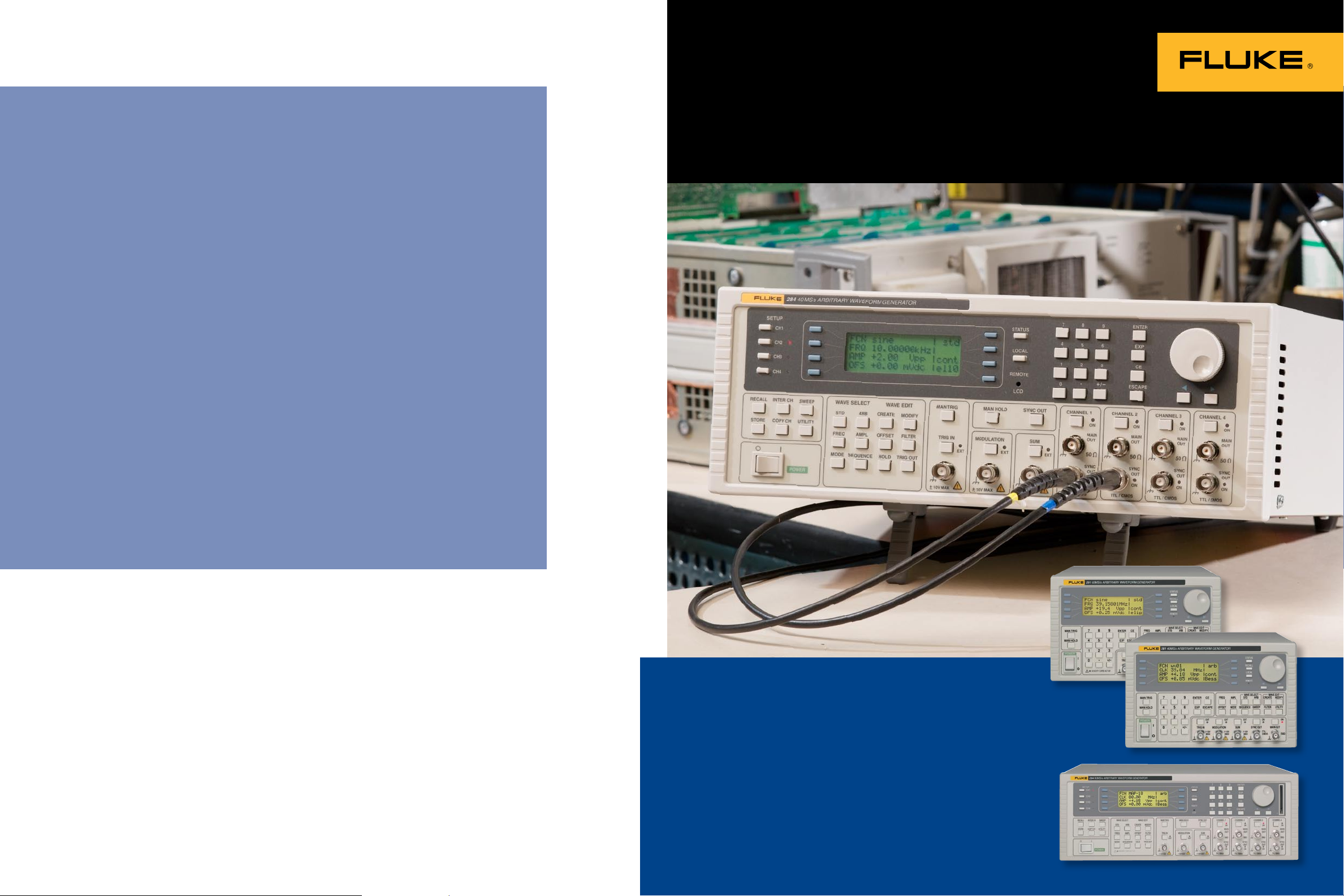
• One, two or four independent
or inter-linked channels
• 40 MS/s or 100 MS/s, up to
1 M words per channel
• Function generator and pulse
generator capabilities
291
281
294
Page 2
2 Fluke 280 and 290 Series
Universal waveform generators offering
superior performance and excellent value
Pulse generator
Waveform sequencing
The Fluke 280 Series and
290 Series Waveform
Generators combine a
true variable clock
arbitrary waveform
generator with a high
performance DDS function generator and pulse
generator in a single
instrument.
Wide model range
The Fluke 280 Series and
290 Series comprise of six models:
• 281 40 MS/s single-channel
waveform generator in 3U half
rack size case.
• 282 40 MS/s two-channel
waveform generator in 3U case.
• 284 40 MS/s four-channel
waveform generator in 3U case.
• 291 100 MS/s single-channel
waveform generator in 3U half
rack size case.
• 292 100 MS/s two-channel
waveform generator in 3U case.
• 294 100 MS/s four-channel
waveform generator in 3U case.
On multi-channel units, each
channel can be operated fully
independently, or multiple channels can be linked using simple
or complex relationships.
A true arbitrary generator
The 280 and 290 Series are
highly sophisticated 12-bit
arbitrary waveform generators
capable of recreating virtually
any waveform. True variable
clock architecture is used with
clock speeds between 0.1 Hz and
100 MHz (40 MHz on 280 Series
units). This architecture avoids
the clock jitter associated with
DDS arbitrary generators and
permits waveform linking,
looping and sequencing.
Waveforms may be defined
with up to 4096 vertical points
and from 8 M to 1 M horizontal
points (4 K to 64 K points on
280 Series units).
Arbitrary waveforms may be
replayed at a specified waveform
frequency, period or sample clock
rate. An external sample clock
can also be used on 290 Series
units allowing seamless on the
fly changes to output frequency.
The 290 series waveform
storage is on removable Compact
Flash cards, making waveform
management easy and effectively
unlimited.
Function generator
Each channel can operate as a
full DDS function generator. High
quality sine, cosine, haversine,
havercosine and square waves
are available between 1 mHz and
16 MHz (280 Series) or up to 50
MHz (290 Series). Triangle, ramp
and sine(x)/x waveforms are
available from 0.1 mHz up to
500 kHz.
Pulse generator
Each channel can generate not
just pulses, but also complex
pulse trains. A pattern of up to
10 pulses can be quickly defined,
with each pulse having its own
amplitude, width and delay.
The whole pulse train pattern
can then be replayed at a user
defined repetition rate. Where
variable rise time pulses are
required, the full arbitrary
function can be used.
Features
1, 2 or 4 waveform channels,
•
independent or linked
40 MS/s or 100 MS/s 12-bit arbitrary
•
waveform capability using true
variable clock architecture
64 K or 1 M point waveform memory
•
per channel
16 MHz or 50 MHz function
•
generators using direct digital
synthesis (DDS)
Multiple standard waveforms includ-
•
ing sine, square, triangle, haversine,
ramp, pulse and sin(x)/x
Pulse train pattern generation for up
•
to 10 pulses
Complex waveform sequencing and
•
looping capability using up to 1024
waveform segments
Wide range sweep, AM, tone
•
switching, signal summing
Inter-channel triggering, summing
•
and phase control
Multiple generators can be easily
•
phase locked
External ARB clock input
•
(290 Series only)
Waveform creation/editing tools built
•
in; sophisticated external Windows
based software included
Built-in trigger generator, gated and
•
triggered burst modes
Tone switching facilitates precision
•
DTMF generation
Unlimited waveform storage using CF
•
memory cards (290 Series only)
GPIB (IEEE-488.2), RS-232 and USB
•
interfaces (280 Series units have
GPIB and RS-232 only)
40 MS/s or 100 MS/s
one, two or four channels
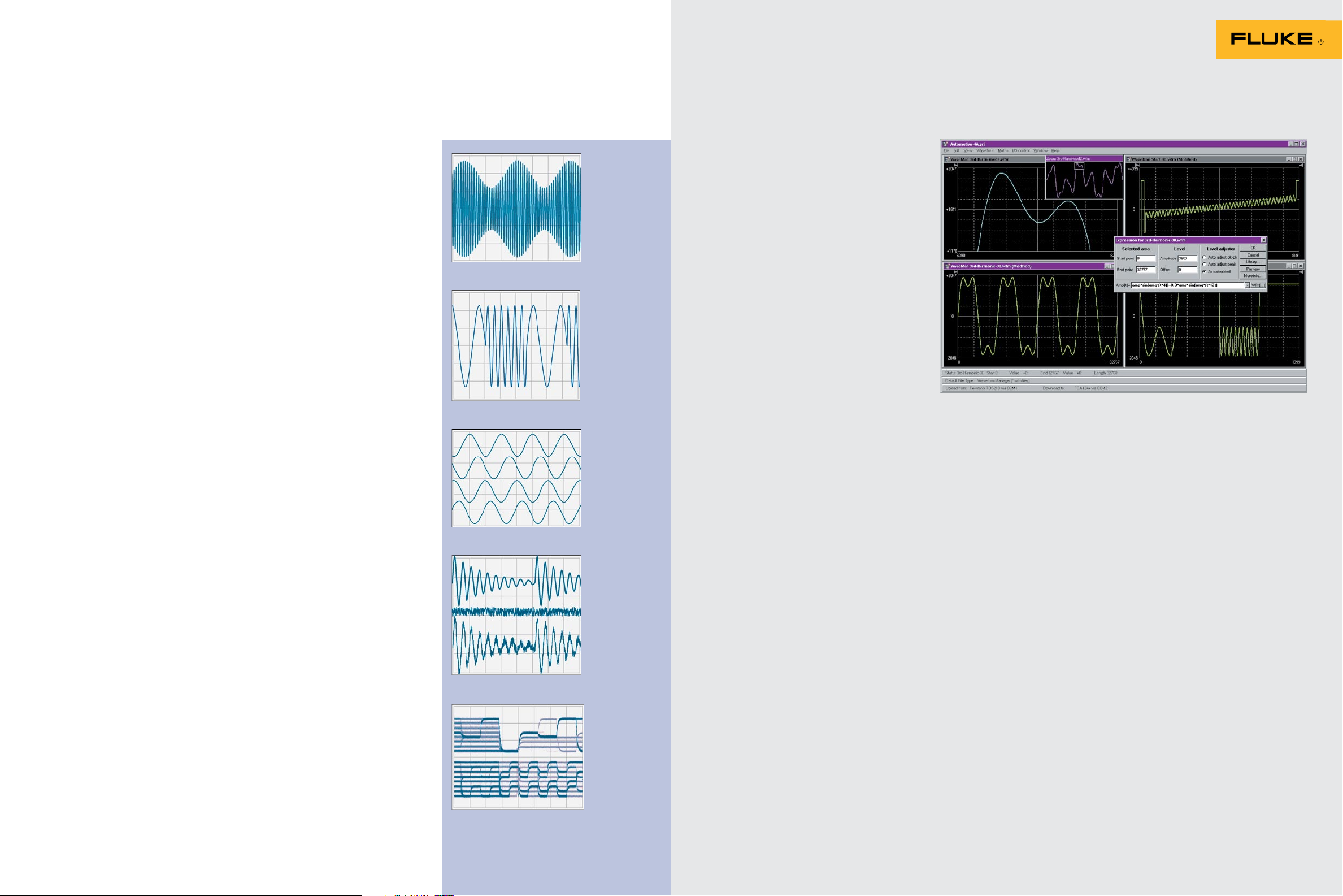
Waveform creation
and editing
Waveform creation and editing
features are in corporated within
the instrument. These in clude
waveform insert, point edit,
line draw, amplitude adjust and
invert.
A wide range of standard
waveforms are avail able for
insertion within an arbitrary
waveform. Sections of existing
arbitrary waveforms can also
be inserted. For more sophisticated waveform creation and
editing, Waveform Manager
Plus soft ware for the Windows®
operating system is provided.
Waveforms created on a PC
can be down loaded to the
instrument via the digital interfaces (or memory card where
fitted).
Memory card storage
Fluke 290 Series units incorporate a CompactFlash memory
card, giving effectively unlimited stor age for waveforms and
setups. Waveform data can be
transferred directly from a PC to
the memory card using the USB
card reader/writer supplied.
GPIB, RS-232, USB
The 280 and 290 Series
incorporate both RS-232 and
GPIB (IEEE-488) interfaces as
standard. 290 Series units also
have a USB interface. These can
be used for loading arbitrary
wave forms and for remote
control of all the instru ment
functions.
Waveform sequencing
The variable clock architecture of the 280 and 290 Series
enables waveforms to be
se quenced. Up to 1024 arbitrary
waveforms may be linked in a
sequence (16 waveforms on 280
Series). Each waveform can have
a loop count of up to 32,768 and
the whole sequence can be run
contin uously or re peated more
than a million times.
For multi-channel models,
waveforms on dif ferent channels
can be ‘daisy chained’ and
looped. By summing the channel
outputs, multiple segments from
multiple channels can be used
to create highly complex waveforms.
Wide range sweep
All waveforms can be swept
over their full fre quency range
at a rate variable between milliseconds and minutes. Sweep
can be linear or logarithmic,
single or continuous. Single
sweeps can be triggered from
the front panel, the trigger input,
or the digital interfaces. Multiple
channels can be swept simultaneously.
Page 3
4 Fluke 280 and 290 Series
Waveform Manager Plus software
Amplitude modulation
Amplitude modulation and
suppressed car rier modulation
are available for all waveforms.
Any channel can be used to
modu late another chan nel.
Alternatively, all channels can
be modulated simul taneously via
the modulation input.
Built-in trigger generator
All waveforms are available as
a triggered burst whereby each
trigger edge will produce one
burst of the carrier. Start and
stop phase is fully variable. Both
triggered and gated modes can
be op erated from the internal
trigger generator, from an
adjacent channel, an external
source or a key press or remote
command. The trigger generator
signal is available as a separate
output if required.
Tone switching
The Fluke 280 and 290 Series
can provide triggered switching
between up to 16 frequencies of
standard or arbitrary waveforms.
Tone switching modes can be
gated, triggered or FSK using
any trig ger source. By summing
two channels together, it is possible to generate precise DTMF
test signals.
Fast and easy to use
All of the main information is
clearly displayed on a backlit
80 character LCD. Eight soft keys
enable fast data editing. Parameters can be entered directly
from the nu meric keypad or
changed with the spin wheel.
On the 2 and 4 channel models,
a Copy Chan nel key enables
similar setups to be created
across multiple channels with
ease.
Multi-channel phase
locking
Any number of channels can
be phase locked with offsets
defined to a resolution of
0.1° (or 360°/waveform points
for arbitrary wave forms). For
applications requiring more than
four channels, multiple generators can be phase locked.
290 Series models can be phase
locked to an external clock and
offer phase continuous
fre quency changes.
All models, including the
281 and 291, have the facility
for phase synchonising to
another similar generator.
Multi-channel summing
Waveform summing sums the
waveform from any channel into
the next channel. Alternatively
any number of chan nels can
be summed with an external
signal. This permits com plex
modulations, such as noise
superim position, to be created.
Inter-channel triggering
and modulation
Because any channel can be
triggered by the previous or next
channel, waveforms on differ ent
channels can be “daisy chained”
and looped. By summing the
channel outputs, many segments
from different channels can
be used to generate the final
waveform. A channel can be
used to AM modulate or SCM
modulate another channel.
Digital modulation
Inter-channel modulation and
summing allows the simulation
of various telecom digital modulation systems.
Amplitude modulation
Tone switching
Multi-channel phase locking
Multi-channel summing
Digital modulation
Advanced waveform creation,
editing and management
software included with all
280 and 290 Series generators
Full waveform building tools includ-
•
ing standard waveforms, mathemati cal
expressions, and freehand drawing
Full waveform building tools includ-
•
ing standard waveforms, mathemati cal
expressions, and freehand drawing
Operates under Windows 95, 98,
•
Millennium, NT, 2000 and XP
Supports vertical resolutions up
•
to 16 bits (65536 points)
Supports horizontal resolutions
•
to over one million points
Provides waveform import and
•
export via clipboard functions
Directly supports waveform
•
upload from some Tektronix DSOs
Supports download and upload
•
via RS-232, GPIB and USB
Waveform building tools
Toolkit
Waveforms can be built in any number
of sec tions using any combination of
the following: standard waveforms,
mathematical expressions, drawn
waveforms, uploaded waveforms,
im ported waveforms (using clipboard),
existing stored waveforms.
Waveform section limits can be defined
via move able cursors, which can be
dragged or positioned numeri cally.
Standard waveforms
The following waveforms are available
directly from the Waveforms dialogue
box: Sine, square, triangle, pulse, ramp,
sinc [sin(x)/x], gaussian, exponent, noise.
The mathematical expression for any
standard waveform can be examined by
opening the expression editor window.
Expression editor functions
The following mathematical operators
are available within the expression
editor: add, subtract, multiply, divide, xn,
sin, cos, arcsin, arccos, abs, log10, loge,
en, square root, floor, ceiling, random,
pulse, in conjunction with constants and
waveforms.
The expressions used for each section
of a waveform are retained and can be
displayed in a drop-down window.
Expression libraries
The mathematical expressions used
for wave form creation can be stored in
libraries. A de fault library is created for
each project that includes a number of
useful examples, including waveshapes
and modulations.
Waveform drawing
functions
Waveforms can be created or edited
using free hand drawing and/or
point-to-point line drawing.
Smoothing
Waveforms can be smoothed using a
running average filter. Start and end
points can be spec ified as well as the
number of points to average.
Single and Multi-Channel Universal ARB Generators 5
Page 4

6 Fluke 280 and 290 Series
Single and Multi-Channel Universal ARB Generators 7
Technical specifications
Waveform
editing/conversion
Toolkit
All of the waveform building tools previously mentioned can be used to edit
existing wave forms. In addition, waveforms can be manipu lated directly using
the following functions:
Resize waveform
Allows a waveform to be resized
horizontally to any length between
4 K to 64 K for 280 and 8 M to1 M for
290. Note: The vertical resolution of a
waveform is automati cally adjusted when
it is downloaded to the generator. Thus
an 8-bit waveform from a DSO will be
expanded to 12 bits if it is downloaded to
a 12-bit generator (and vice versa)
Waveform mathematics
The Waveforms Maths function allows
wave forms to be combined and manipulated inde pendently of the expression
editor. Waveforms can be scaled, offset,
added, subtracted or multi plied using
dialogue boxes. Waveforms can also be
combined and manipulated within the
expression editor, giving access to the full
range of mathematical functions.
Input/output functions
File formats
Waveforms can be read from and saved
as any of the following formats: WFM
(binary), NRM (nor malised data in ASCII),
WAV (WaveCAD), ASC (WaveCAD), DSF
(Tektronix DSO).
Waveform download/upload
Waveforms can be downloaded/uploaded
to/from Fluke arbitrary generators (or
certain Tektronix DSOs) using either an
RS-232 or GPIB (IEEE-488) interface or,
for the 290 Series, a USB interface.
Clipboard functions
Waveforms can be imported to the
program and exported from the program
using the Windows® Clipboard.
Waveform import uses the “Text”
clipboard for mat (i.e. numeric lists). This
enables waveforms to be imported from
spreadsheets such as Excel
and from mathematical programs such
as MathCad. Values are automatically
normalised and re-scaled.
Waveform export creates multiple
clipboard for mats of Text (normalised
numeric values be tween ± 1), Bitmap (as
per on-screen display) and Picture (metafile retaining waveform vector prop erties).
Pictures or bitmaps can be pasted into
programs such as Word for documentation purposes.
®
software
Display area and printing
Multiple waveform windows can be open
simulta neously. Each window is fully
scaleable. Vari able zoom is provided with
panning from a “navigator” sub-window.
Waveform section limits can be
defined via moveable cursors that can
be dragged or posi tioned numerically.
Waveforms can be printed with
automatic anno tation and scaling.
Management and
utilities
Projects
To maintain good housekeeping, waveforms can be organized into “projects”
with separate direc tory structures. Each
project maintains its own li brary of
expressions. Waveforms and expressions
can be imported and exported from other
projects.
Instrument setup
The instrument setup screen enables
options for the waveform generator to
be set from the pro gram. Examples of settable options are output amplitude, clock
frequency and trigger source.
Help
Full on-screen Help is available with a
hyperlinked contents table.
Variable-clock ARB
architecture
Direct replay for jitter-free
waveforms
All Fluke 280 and 290 Series units
generate arbitrary waveforms using a
variable clock architecture rather than
DDS. This ensures that every point in the
waveform is replayed exactly as it was
defined, the rate of replay being set by
the clock frequency.
By contrast, a DDS arbitrary generator
uses a fixed clock frequency and varies
the replay rate by duplicating or omitting waveform points. Unless there is
an integer relationship between the
desired replay rate, clock fre quency and
waveform length, each “cycle” of the
waveform will differ from the previous
one, resulting in jitter.
Sequencing for increased
waveform length
Variable clock architecture also allows
sequencing and looping. The 64K words
of waveform memory per channel provided in Fluke 280 Series units can be
used to create arbitrary waveforms with
many more than 65536 points.
Many real-world waveforms include
repetitive elements. By using a segment of the memory to recreate each
repeating element, the waveform can be
constructed by a “sequence” in which
the individual elements are re played
in a defined order and with a defined
number of repetitions (loop count). In this
way waveforms can be created with a
much greater number of points than the
waveform memory size.
DDS arbitrary generators cannot do
this and the effective waveform length
is limited to the actual waveform
memory size.
Fluke 290 Series: the
next step forward
The design of the new Fluke 290 Series
generators is based upon extensive
expe rience of actual user requirements.
So in addition to raising the maximum
clock speed from 40 MHz to 100 MHz,
a number of other important features
have been added that meet the needs of
particular groups of customers.
1 M word waveform memory
Some users require very long arbitrary
waveforms. 290 Series units incorporate
1,048,576 words of waveform memory
per channel. Thus, even long and complex waveforms that have no repetitive
elements can be accommodated.
Compact Flash memory card storage
provides effectively unlimited stor age for
waveforms. Greater sequencing capability (up to 1024 segments) gives even
more flexibility in waveform reconstruction.
External ARB clock input
Some applications require that the
arbitrary waveform is clocked in direct
synchronism with an external signal.
Fluke 290 Series units incorporate an
external ARB clock input that can be
used to clock any number of channels at
any rate from dc up to 50 MHz.
It should be noted that DDS arbitrary
generators have no such capability.
Page 5

8 Fluke 280 and 290 Series
Single and Multi-Channel Universal ARB Generators 9
System clock architecture
All Fluke 290 Series units incorporate a separate clock generator for
each chan nel, allowing completely
independent operation.
On the Fluke 282 and Fluke
284, channel synchronization is
achieved by defining one channel
as the master channel and driving
the other channel(s) from its clock.
The Fluke 292 and 294 provide
a further option by incorporating
an additional independent system
clock generator. The system clock
cre ates an internal version of the
external ARB clock signal and can
generate frequencies between 0.1
Hz and 50 MHz.
When the system clock (or
external ARB clock) is used to drive
multiple channels, phase skew is
significantly reduced and frequency
changes can be made without any
discontinuities.
The system clock output is also
available on the rear panel to drive
external circuitry or the external
ARB input of another generator
when more than four channels are
required.
Auxiliary sinewave output
The output of the master clock
generator is also available as a
fixed level sinewave. When not
being used as the master for
channel synchronization, this can
be used as another independent
variable frequency genera tor over
the range 0.1 Hz to 50 MHz,
providing the equivalent of three
or five channel outputs.
Specifications apply between
18 °C to 28 °C after 30 minutes
warm up, at maximum output
into 50 Ω.
Arbitrary waveforms
Waveform parameters
280 Series 290 Series
Waveform memory 64k points/ch
Waveform length 4 to 65,536 points
Vertical resolution 12 bits (4096 levels)
Sample clock rate 0.1 Hz to 40 MHz 0.1 Hz to 100 MHz (1)
Clock resolution 4 digits 8 digits
Clock accuracy < 10 ppm for 1 year (± 1 digit of setting)
Clock temp. stability Typically < 1 ppm/ °C
Waveform storage 256K Words
Max. waveforms 100 500 per card
Note 1: 290 Series generators can also use an external sample clock, dc to 50 MHz.
Non-volatile RAM
Waveform creation and editing
All Models
Internal Basic arbitrary waveform creation and editing tools are built
External All Fluke 280 and 290 series units are supplied with Wave-
into the instrument. Arbitrary waveforms can be built-up us ing
insertion of standard waveforms between points, point by point
value setting, and straight line drawing between points.
form Man ager Plus software for Windows which provides full
waveform creation, editing and management. Waveforms are
trans ferred using the digital interfaces or memory card.
Sequence
A number of waveforms can be linked and played as a
sequence. Each waveform can have a loop count of up
to 32,768. A sequence of waveforms can be looped up to
1,048,575 times or run continuously.
280 Series 290 Series
Max. waveforms in a
sequence
16 1024
Output filter
The output filter type is selectable. This can be used to optimize
a particular waveshape.
280 Series 290 Series
Filter choice 16 MHz elliptic, 10 MHz
elliptic, 10 MHz Bessel
or none
1M points/ch
8 to 1,048,576 points
CF Memory Cards
(32 MB to 1 GB size)
40 MHz elliptic, 20
MHz Bessel or none
Standard waveforms
Sine, square, triangle, dc, positive ramp, negative ramp, sin(x)/x,
pulse, pulse train, cosine, haversine and havercosine.
All waveforms
280 Series
Frequency accuracy < 10 ppm for 1 year
Temp. stability Typically < 1 ppm/ °C
Output level
Sine, cosine, haversine, havercosine
Frequency range 0.1 mHz to 16 MHz 0.1 mHz to 40 MHz
Freq. resolution 0.1 mHz or 7 digits 0.1 mHz or 10 digits
Harmonic distortion < 0.1 % THD to 100 kHz;
Nonharmonic spurii < –65 dBc to 1 MHz,
Square
Frequency range 1 mHz to 16 MHz 1 mHz to 50 MHz
Freq. resolution 1 mHz or 4 digits 1 mHz or 8 digits
Freq. accuracy ± 1 digit of setting
Rise and fall times < 25ns
Pulse and pulse train
Period range 100 ns to 100 s 40 ns to 100 s
Period resolution 4 digits 8 digits
Period accuracy ± 1 digit of setting
Delay range -99.99s to + 99.99s
Delay resolution 0.002 % of period
Width range 25 ns to + 99.99 s 10 ns to + 99.99 s
Width resolution 0·002 % of period
Rise and fall times < 25 ns
Note that the pulse width and absolute value of the delay may
not exceed the pulse period at any time. Pulse trains of up to
10 pulses may be specified, each pulse having independ ently
defined width, delay and level. The baseline voltage is separately defined and the sequence repetition rate is set by the
pulse train period.
2.5 mV to 10 V pp into 50 Ω (5 mV to 20 V pp e.m.f.)
280 Series 290 Series
< –65dBc to 20 kHz,
< –50dBc to 300 kHz,
< -35dBc to 10 MHz
< -30 dBc to 16 MHz
< –65 dBc + 6 dB/octave
1 MHz to 16 MHz
280 Series 290 Series
< 8ns
280 Series 290 Series
(25 ns minimum)
(25 ns minimum)
< 8 ns
< 0.15 % THD to 100 kHz;
< -60 dBc to 20 kHz,
< -50 dBc to 1 MHz,
< -40 dBc to 10 MHz,
< -30 dBc to 40 MHz
< -60 dBc to 1 MHz,
< -60 dBc + 6 dB/octave
1 MHz to 40 MHz
0.001 % of period
(10 ns minimum)
0.001 % of period
(10 ns minimum)
Triangle
280 Series 290 Series
Frequency
range
Frequency
resolution
Linearity
error
0.1 mHz to 100 kHz 0.1 mHz to 500 kHz
0.1 mHz or 7 digits 0.1 mHz or 10 digits
< 0.1 % to 30 kHz
Ramps and sin(x)/x
280 Series 290 Series
Frequency
range
Frequency
resolution
Linearity
error
0.1 mHz to 100 kHz 0.1 mHz to 500 kHz
0.1 mHz or 7 digits 0.1 mHz or 10 digits
< 0.1 % to 30 kHz
Noise function (290 Series only)
Digital noise generated by a 35-bit linear
feedback register clocked at 100 MHz. User’s
external filter defines bandwidth and response.
Page 6

Operating modes
Continuous
Waveform runs continuously.
Triggered burst
Each active edge of the trigger signal will produce one burst
of the waveform.
280 Series 290 Series
Carrier waveforms All standard and arbitrary waveforms
Max. carrier
frequency
Number of cycles 1 to 1,048,575
Trigger repetition 0.005 Hz to 100 kHz internal, dc to 1 MHz external.
Trigger signal Source Internal from keyboard, previous channel, next
Trigger start/stop
phase
1 MHz or the maximum for the selected
wave form if lower. 40
Msamples/s for ARB and
Sequence.
channel or trigger generator. External from TRIG IN
or remote interface.
± 360° settable with 0.1° resolution, subject to
waveform frequency and type.
2.5 MHz or the maximum for the selected
waveform if lower. 100
Msamples/s for ARB and
Sequence.
Tone switching modes:
Gated: The tone is output while the trigger
signal is true and stopped, at the end of the
current waveform cycle, while the trigger
signal is false. The next tone is output
when the trigger signal is true again.
Triggered: The tone is output when the
trigger signal goes true and the next tone is
output, at the end of the current waveform
cycle, when the trigger signal goes true
again.
FSK: The tone is output when the trigger
signal goes true and the next tone is
output, immediately, when the trigger
signal goes true again. Using 2 channels
with their outputs summed together it is
possible to generate DTMF test signals.
Trigger generator: Internal source 0.005
Hz to 100 kHz square wave adjustable in
10 us steps. 3-digit resolution. Available for
external use from any SYNC OUT socket.
Outputs
Main output—One for each channel
280 Series 290 Series
Output impedance
Amplitude range 5 mV to 20 V pp open circuit (2.5 mV to 10 V pp into
Amplitude accuracy
Amplitude flatness ± 0.2 dB to 200 kHz;
DC offset range
DC offset accuracy Typically 3 % ± 10 mV, unattenuated
Resolution 3 digits or 1 mV for both Amplitude and DC Offset
Auxiliary sine output
280 Series 290 Series 292/294
n/a n/a Nominal 1V p-p sinewave, frequency set by
50 Ω
50 Ω). Amplitude can be specified open cir cuit (hi Z)
or into an assumed load of 50 Ω or 600 Ω in Vpk-pk,
Vrms or dBm.
2 % ± 1 mV at 1 kHz into 50 Ω
± 1dB to 10 MHz;
± 2.5 dB to 16 MHz
± 10 V from 50 Ω. Offset plus signal peak limited
to ± 10 V.
system clock, frequency 0.1 Hz to 50 MHz
± 0.2 dB to 1 MHz;
± 0.4 dB to 40 MHz
Gated
Waveform will run while the Gate signal is true and stop while false.
280 Series 290 Series
Carrier waveforms All standard and arbitrary waveforms
Max. carrier
frequency
Number of cycles 1 to 1,048,575
Trigger repetition 0.005 Hz to 100 kHz internal, dc to 1 MHz external
Gate signal source Internal from keyboard, previous channel, next
Gate start/stop phase ± 360° settable with 0.1° resolution, subject to
1 MHz or the maximum
for the selected wave form
if lower. 40 Msamples/s
for ARB and Sequence
channel or trigger generator. External from TRIG IN
or remote interface.
waveform frequency and type
2.5 MHz or the maximum for the selected
waveform if lower. 100
Msamples/s for ARB and
Sequence
Sweep
Frequency sweep capability is provided for both standard and
arbitrary wave forms. Arbitrary waveforms are expanded or condensed to exactly 4096 points and DDS techniques are used to
perform the sweep.
280 Series 290 Series
Carrier waveforms All standard and arbitrary except pulse, pulse train
Sweep mode Linear or logarithmic, triggered or continuous
Sweep direction Up, down, up/down or down/up.
Sweep range From 1 mHz to 16 MHz in
Sweep time 30 ms to 999 s 1 ms to 999 s
Marker Variable during sweep
Sweep trigger source The sweep may be free run or triggered from the
Sweep hold Sweep can be held / restarted by the HOLD key
and sequence
one range
following: Manually from keyboard. Externally from
TRIG IN input or remote interface
From 1 mHz to 40 MHz in
one range
Multi channel sweep
(multi-channel units only)
Any number of channels may be swept simultaneously. Amplitude, Offset and Waveform can
be set independently for each channel. For Fluke
280 units the sweep parameters will be the
same for all channels. For Fluke 290 units the
sweep parameters can be set independently for
each channel.
Tone switching
Capability provided for both standard and
arbitrary waveforms. Arbitrary wave forms are
expanded or condensed to exactly 4096 points
and DDS techniques are used to allow instantaneous frequency switching.
280 Series 290 Series
Carrier
waveforms
Frequency
list
Trigger
repetition
rate
Trigger
source
Tone
switching
modes
All except pulse, pulse train and sequence
Up to 16
frequencies from
1 mHz to 10 MHz
0.005 Hz to 100 kHz internal. dc to 1MHz
exter nal. Usable repetition rate and
waveform fre quency depend on the tone
switching mode.
Internal from keyboard, previous channel,
next channel or trigger generator. External
from TRIG IN or remote interface.
Gated, Triggered or FSK (see box top right)
Up to 16 frequencies
from 1mHz to 40 MHz
Sync out—One for each channel
Multifunction output user definable or automatically selected to
be any of the following:
280 Series 290 Series
Waveform sync: (all waveforms) Square wave with 50 % duty cycle at the main waveform frequency, or pulse
Position markers: (Arbitrary only) Any point(s) on the waveform may have associated marker bit(s) set high or low
Burst done Produces a pulse coincident with the last cycle of a burst
Sequence sync Produces a pulse coincident with the end of a waveform sequence
Trigger Selects the current trigger signal. Useful for syn chronizing burst or gated signals.
Sweep sync Outputs a pulse at the start of sweep to synchronize an oscilloscope or recorder
Sweep marker N/A Additional pulse for use as sweep marker
Phase lock out Used to phase lock two generators. Produces a positive edge at the 0° phase point.
Signal level Logic levels of < 0.8 V and > 3 V for
Signal level: (sweep sync. only) N/A 3 level waveform - as above but plus
coincident with the first few points of an arbitrary waveform
all outputs
Logic levels of < 0.8 V and > 3 V for
all outputs except Sweep Sync
narrow +1 V pulse at marker
Single and Multi-Channel Universal ARB Generators 11
Page 7

Single and Multi-Channel Universal ARB Generators 13
Inputs
Trig in
280 Series 290 Series
Frequency range DC to 1 MHz
Signal range Threshold nominally TTL
Min. pulse width 50 ns, for Trigger/Gate; 50 us for Sweep mode
Polarity Selectable as high/rising edge or low/falling edge
Input impedance
level; maximum input
± 10 V
Typically 10 kΩ
Threshold adjustable
over ± 5 V range;
maximum input ± 10 V
Modulation in
280 Series 290 Series
Frequency range DC to 100 kHz DC to 100 kHz
VCA signal range Approximately 1 V pk-pk for 100 % level change at
SCM signal range Approximately ± 1 V pk for maximum output.
Input impedance
maximum output
Typically 1 kΩ
Sum in
280 Series 291 292/294
Frequency range DC to 8 MHz DC to 30 MHz DC to 16 MHz
Signal range Approximately 2 V pk-pk input for 20 V pk-pk out put
Input impedance
Typically 1 kΩ
Ref clock in/out
280 Series 290 Series
Set to input Input for an external 10MHz reference clock.
Set to output Buffered version of the internal 10 MHz clock. Output
Set to phase lock Used together with SYNC OUT on a master and
TTL/CMOS threshold level
levels nominally 1 V and 4 V from 50 Ω
TRIG IN on a slave to synchronize (phase lock) two
separate generators
ARB clock in/out
290 Series generators can use an external signal as the arbitrary
waveform clock. The 292 and 294 also include an internal system
clock generator (in addition to the individual channel clock generators). The output of this system clock can be made available to drive
external circuitry or the input of another generator.
280 Series 291 292/294
Set to input N/A Input for an external Arb clock.
Set to output N/A N/A Outputs System Clock,
TTL/CMOS threshold level.
logic level < 0.8 V to > 3 V
Hold
Holds an arbitrary waveform at
its current position. A TTL low
level or switch clo sure causes the
waveform to stop at the current
position and wait until a TTL high
level or switch opening which
allows the waveform to continue.
The front panel MAN HOLD key
or remote command may also be
used to control the Hold function.
While held the front panel MAN
TRIG key or remote command
may be used to return the waveform to the start. The Hold input
may be enabled independently
for each channel. Input impedance is10kΩ.
Channel relationships
The channels of a multi-channel
unit can be operated entirely
independently, as if they were
separate generators. The “copy”
key allows the settings of any
channel to be instantly copied to
another when required.
Alternatively, inter-channel
relationships of modulation,
summing, triggering, or phase
locking can be set up.
Multi channel sweep
Any number of channels may be
swept simultaneously. Amplitude,
Offset and Waveform can be set
independently for each channel.
For 280 Series units, the sweep
parameters will be the same
for all channels. For 290 Series
units,the sweep parameters can
be set independently for each
channel.
ARB clock out
See ARB clock In/Out within INPUTS section.
Cursor/marker out (280 Series units only)
Adjustable output pulse for use as a marker in
sweep mode or as a cursor in arbitrary waveform editing mode. Can be used to modulate the
Z axis of an oscilloscope or be displayed on a
second ‘scope channel.
280 Series 290 Series
Signal level: Adjustable from
Output
impedance:
nominally 2 V to 14
V, normal or inverted;
ad justable width as a
cursor
600 Ω typical
N/A
N/A
System clock (292/294 only)
The 292/294 units incorporate an additional
frequency generator, which can be used as a
clock source for multi-channel arbitrary waveforms and as an auxiliary output.
280
Series
Frequency
range
Frequency
resolution
N/A N/A DC to 50 MHz
N/A N/A 0.1 Hz
The output of the system clock is available as a
1 volt pk-pk sinewave at the Auxiliary Sine Out
socket, and as a logic level squarewave at the
Ext. ARB In/Out socket.
When not being used as a clock source for
multi-channel arbitrary waveforms, the system
clock provides an independent fixed amplitude
sine or square output which is additional to the
two or four main channel outputs.
292/294
291
Inter-channel modulation
The waveform from any channel may be used to Amplitude
Modulate (AM) or Suppressed Carrier Modulate (SCM) the next
channel. Alternatively any num ber of channels may be
Modulated (AM or SCM) with the signal at the MODULA TION
input socket.
282/284/292/294
Carrier frequency Entire range for selected waveform
Carrier waveforms All standard and arbitrary waveforms
Modulation types AM: Double sideband with carrier. SCM: Double
Modulation source Internal from the previous channel. External from
Frequency range DC to > 100 kHz
Internal AM depth 0 % to 105 %.
Internal AM resolution 1 %
Carrier suppression
(SCM)
External modulation
signal range
sideband suppressed carrier.
Modulation input socket. The external modulation
signal may be applied to any num ber of channels
simultaneously.
> 40 dB
VCA: Approximately 1V pk-pk for 100 % level
change at maximum output. SCM: Approximately ±
1 V pk for max. output.
Inter-channel analog summing
Waveform Summing sums the waveform from any channel into
the next channel. Alternatively any number of channels may be
summed with the signal at the SUM input socket.
282/284 292/294
Carrier frequency Entire range for selected waveform
Carrier waveforms All standard and arbitrary waveforms
Sum source Internal from the previous channel. External from
Frequency range DC to > 8 MHz. DC to > 16 MHz.
External signal range Approx. 5 V pk-pk input
Input impedance
SUM IN socket
for 20 V pk-pk output
Typically 1 kΩ
Approx. 2 V pk-pk input
for 20 V pk-pk output
Frequency range N/A DC to 50 MHz.
Max. input voltage N/A +5 V, -1 V
12 Fluke 280 and 290 Series
Page 8

Single and Multi-Channel Universal ARB Generators 15
Multi-channel operation
Inter-channel phase
locking
Two or more channels may be
phase locked together. Each
locked channel may be assigned
a phase angle relative to the
other locked channels. With one
channel assigned as the Master
and other channels as Slaves, a
fre quency change on the master
will be repeated on each slave
thus allowing multiphase waveforms at the same frequency to
be easily generated. The signals
from the REF IN/OUT socket and
the SYNC OUT socket can be used
to phase lock two instruments
where more than 4 channels
are re quired. Different condition
apply to Standard waveforms
generated using DDS tech niques
(sine, cosine, haversine,
havercosine, triangle, ramps and
sinex/x), and those generated
using variable clock arbitrary
waveform techniques which
include square, pulse and pulse
train. Arbitrary waveforms and
waveform sequences may be
phase locked to the Master
channel, but certain constraints
apply to waveform lengths and
clock frequency ratios. 292/294
arbitrary waveforms and waveform sequences can alternatively
be clocked from a separate
internal clock generator (Sys tem
clock), or from an external clock
input (external ARB clock). When
using these clock sources, the
restrictions that apply when using
the Master channel as the clock
source are eliminated. In addition, frequency changes require
no settling time to re-establish
phase locking, and thus phase
continuous frequency changing or
sweeping is possible.
282/284 292/294
Phase resolution:
(DDS waveforms)
Phase resolution:
(Non DDS waveforms)
Clock source Master channel Master Channel, System
Phase error < ± 10 ns < ± 5 ns (internal clock)
0.1 degree
0.1 degree or 360 degrees/number of points
Clock or Ext. ARB clock
< +/-2 ns (external ARB
or system clock)
N.B. DDS waveforms are Sine, Cosine, Haversine, Havercosine,
Triangle, Ramps and Sin(x)/x. Non DDS waveforms are Pulse,
Pulse Train, and all Arbitrary waveforms.
Inter-channel triggering
Any channel can be triggered by the previous or next channel.
The previous/next connections can be used to ’daisy chain’ a
trigger signal from a ‘start’ channel, through a number of channels in the ‘chain’ to an ‘end’ channel. Each channel receives the
trigger out signal from the previous (or next) channel, and drives
its selected trigger out to the next (or previous) channel. The ‘end’
channel trigger out can be set up to drive the ‘start’ chan nel,
closing the loop. In this way, complex and versatile inter-channel
trigger schemes may be set up. Each channel can have its trigger
out and its output waveform set up in dependently. Trigger out
may be selected from Waveform End, Position Markers, Sequence
Sync or Burst Done.
Interfaces
Full remote control and waveform transfer is available through the
digital in terfaces.
280 Series 290 Series
IEEE488 Conforms with IEEE488.1 and IEEE488.2
RS232 Variable baud rate, 9600
baud maximum
USB N/A Conforms with USB1.1
Variable baud rate, 38400
baud maximum
General
280 Series 290 Series
Display 20 character x 4 row alphanumeric LCD
Data Entry Keyboard selection of mode, wave etc., value entry direct by
Memory Card N/A Removable card slot con forming to
Waveform
Storage:
(non volatile)
Stored Settings Up to 9 full setups Up to 500 full setups per CF card
numeric keys or by rotary control
the Compact Flash standard. Sizes
32 MB to 1 GB.
Up to 100 waveforms
within 256 K words
Up to 500 waveforms per CF card
Mechanical, power, compliance
281 291 282 292 284 294
Width 212 mm (½ rack) 350 mm
Height 130 mm (3 U) 130 mm (3 U)
Length 335 mm 335 mm
Weight 4.1 kg 4.2 kg 7.1 kg 5.9 kg 7.2 kg 6.0 kg
Power A B A C A C
A = 230 V, 115 V or 100 V ± 14 %, 50/60 Hz, adjustable internally B = 230 V,
115 V or 100 V ± 14 %, 50/60/400 Hz, adjustable internally C =100 V to 230
V ± 14 %, 50/60/400 Hz, universal input
Maximum VA 40 60 75 150 100 150
Temperature Operating Range +5 °C to 40 °C, 20-80 % RH Storage
Environmental Indoor use at altitudes to 2000 m, Pollution Degree 2
Safety Complies with EN61010-1
EMC Complies with EN61326
Range -20 °C to +60 °C.
14 Fluke 280 and 290 Series
 Loading...