

Page 1
The future of installation
testing is here
The 1650 Series
Multifunction Testers
Page 2

1650 Series
Safer, easier installation testing.
Robin and Fluke joined forces in 1999 to become the largest supplier of hand-held test and measurement
equipment in Europe. These breakthrough products are the result of a combined experience of over 50
years in instrument design and development.
The 1650 Series testers verify the safety of electrical installations in domestic, commercial and industrial
applications. They can ensure that fixed wiring is safe and correctly installed to meet the requirements of
IEC 60364 and BS 7671 16th Edition IEE Wiring Regulations.
The unique ergonomic design, low weight, and padded neck-strap to free your hands, make operating a
1650 Series multifunction tester a pleasure. With easy-to-operate controls and a large display with
exceptionally wide viewing angle, it’s also comfortable and safe to use.
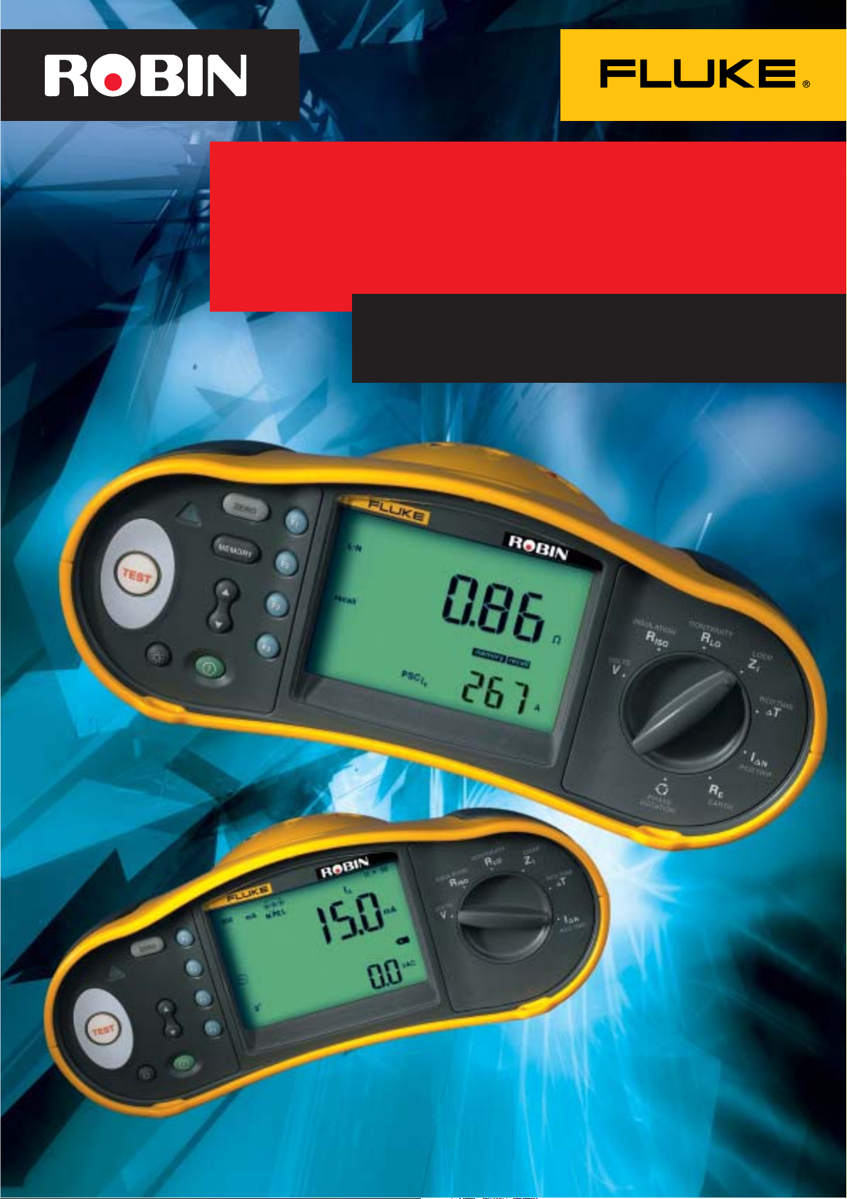
Select from two models
1652
1652: Performs all basic installation tests including
continuity/insulation/loop impedance, RCD tripping time,
RCD tripping current level and RCD auto-testing
1653: As 1652 but with earth resistance and phase sequence
measurement. Has internal memory and a PC interface for
documentation and reporting
1653
(see back page for a comparison chart)
1
Phase/Earth Voltage warning indicator
2
On/off button
3
Press to test button
4
Function buttons to assist easy navigation
5
Memory mode button
6
Scroll memory locations button
7
Backlight button
8
Test lead resistance zero button
8
1
5
6
3
27
4
Page 3

Learn in minutes, test in seconds.
Save time on every installation.
• Easy: simply turn the knob, press the button and
see the results
• Efficient: measure loop impedance without tripping
RCDs, eliminating the need to bypass them
• Rugged: withstands a one-meter drop for
demanding field use.
• Safe: slim probe with test button keeps your eyes
on the panel while probing hard to reach points
• Comfortable: compact and lightweight (less than
1.2 kg) for all day testing
• Compliant: meets all relevant standards including
BS EN 61557
The unique curved shape, ergonomic control layout and
padded neck-strap ensure comfort in use.
Performs all electrical installation tests including
1
Voltage and frequency
2
Insulation resistance
3
Continuity
4
3
2
1
4
5
6
7
8
Loop impedance (with patented non-trip technology)
5
RCD tripping time
6
RCD tripping current
7
Earth resistance (model 1653)
8
Phase sequence (model 1653)
Page 4

R
LO
Continuity (R
Test continuity of live and protective
conductors
Time-saving 'auto-null' feature
•
subtracts lead resistance from
measurements (and stores it in
memory even after power-down)
Wiring connection check indication
•
and live circuit detection for added
safety
High-resolution measurements down
•
to 0.01 1
LO
)
RCD
Carry out functional trip testing and
current tripping level tests
Test wide range of RCDs (both models)
•
Test DC-sensitive and delayed-
•
response RCDs
Automated test sequence function for
•
rapid RCD testing
RCD Tripping Current Test (ramp test)
•
Wiring connection check indication
•
for added safety
Phase selector switch
•
6
I
N
Voltage and frequency (V)
Dual display gives simultaneous
•
readout of mains voltage and
frequency
R
ISO
Insulation resistance (R
Test the insulation resistance of live
and protective conductors
Insulation test voltages of 50, 100,
•
250, 500 and 1000 V cover all
applications including telecom
(depending on model)
Clear indication of applied voltage
•
Auto discharge allows fast and safe
•
discharge of electrical energy in
capacitive circuits
Added safety through live circuit
•
detection, to check and inhibit test if
circuit under test is live
ISO
)
Loop impedance (Z
Measure earth-loop or line impedance
Advanced and patented loop
•
measurement technology prevents
RCD tripping and guarantees
consistent readings after multiple
tests
0.01 1 resolution on loop
•
measurements
Auto-null to remove test-lead
•
resistance from measurement
Prospective short-circuit/
fault current (PSC/PFC)
Measure the potential fault current
between phase/neutral and
earth/neutral conductors
Simultaneous read-out with loop
•
impedance
1 A resolution on measurements
•
)
I
Z
I
Earth resistance (R
(1653 only)
Measure resistance to earth of
electrodes, stakes and earthing mats
Test with auxiliary earth spikes in the
•
ground
Three-wire tests for accurate
•
measurement
User selectable safety voltage level of
•
50 or 25 V
Phase sequence (1653 only)
Test phase sequence rapidly on three
•
phase systems
4
-
)
E
Page 5

Slim probe design
Thanks to its slim probe with integral test
button, you can safely make one-handed
measurements on hard to reach points,
while keeping your eyes on the panel.
Professional reports
Up to 500 test results can be
stored in the 1653 installation
tester. The data stored for each
measurement consists of the test
function, user selectable test
conditions and unique references.
Model 1653 has an IR port and adaptor to enable the results to
be uploaded to a computer for preparing professional reports
using (optional) FlukeView™ Forms software. Reports can easily
be customized to suit individual requirements. Standard formats
are also available.
Page 6

More functions in one tool
AC Voltage Measurement
Range Resolution Accuracy Input Overload
500 V 0.1 V 0.8% + 3 3.3 M1 660 Vrms
Continuity Testing
Range Resolution Test Current Open Circuit Accuracy
(autoranging) Voltage
20 1 0.01 1
200 1 0.1 1 > 200 mA > 4 V ± (1.5%+3 dgt.)
2000 1 1 1
Insulation Resistance Measurement
Model Test Voltages Accuracy of Test Voltage
1652 250 - 500 - 1000 V +10%, -0%
1653 50 –100 - 250 - +10%, -0%
50 Hz - 60 Hz Impedance Protection
(at rated test current)
500 - 1000 V
Test Voltage Insulation Resolution Test Current Accuracy
50 V 10 k1 to 50 M1 0.01 M1 1 mA ± (3%+3 dgt.)
100 V 100 k1 to 20 M1 0.01 M1 1 mA ± (3%+3 dgt.)
250 V 100 k1 to 200 M1 0.1 M1 1 mA ± (1.5%+3 dgt.)
500 V 100 k1 to 200 M1 0.1 M1 1 mA ± (1.5%+3 dgt.)
1000 V 100 k1 to 200 M1 0.1 M1 1 mA ± (1.5%+3 dgt.)
Auto Discharge Discharge time constant, 0.5 second
Live Circuit Detection Inhibits test if terminal voltage > 30 V prior to
Maximum Capacitive Load Operable with the 5 µF load
20 M1 to 100 M1 0.1 M1 @ 100 k1 ± (3%+3 dgt.)
200 M1 to 500 M1 1 M1 @ 500 k1 + 10%
200 M1 to 1000 M1 1 M1 @ 1 M1 + 10%
Resistance
Range
@ 50 k1
@ 250 k1
for C = 1 µF or less.
initiation of test.
Loop Impedance Measurement
Measuring Range 100 – 500 V AC (50/60 Hz)
Input connection Loop Impedance: phase to earth
(soft key selection) Line impedance: phase to neutral
Limit on consecutive tests Automatic thermal shutdown after 50
Range Resolution Accuracy
20 1 0.01 1
200 1 0.1 1 ± (3%+10 digits)
2000 1 1 1
consecutive tests at 10 second intervals
(typical)
PFC, PSC Test
Computation PFC or PSC determined by dividing measured
Range 0 to 10 kA
Resolution and Units lk< 1000 A 1 A
Accuracy Determined by accuracy of loop resistance and
mains voltage by measured loop (L-PE)
resistance or line (L-N) resistance
lk* 1000 A 0.1 kA
mains voltage measurements.
Page 7

RCD Testing
RCD Type Model 1652 Model 1653
1
AC
AC
4
AG ✓✓
2
G ✓✓
3
S ✓✓
AS ✓✓
1
AC – Responds to AC
2
G – General, no delay
3
S – Time delay
4
A – Responds to pulsed signal
Tripping Time Test (6T)
Current Settings Multiplier Current Accuracy
10, 30, 100, 300, 500, 1000 mA
10, 30, 100, 300, 500, 1000 mA
10, 30 mA x 5 ±10%
x1/
2
x 1 +10% -0%
+0% - 10% of test current
Current Multiplier *RCD Type Measurement Range Trip Time Accuracy
Europe UK
x1/
2
x1/
2
x 1 G 310 ms 310 m s
x 1 S 510 ms 510 m s
x 5 G 50 ms 50 ms
x 5 S 160 ms
*G – General, no delay
*S – Time delay
G 310 ms 2000 ms
S 510 ms 2000 ms
160 m s
±(1% Reading + 1 digit)
±(1% Reading + 1 digit)
±(1% Reading + 1 digit)
±(1% Reading + 1 digit)
±(1% Reading + 1 digit)
±(1% Reading + 1 digit)
Tripping current (ramp) test
Current Range Step size Dwell time Trip Current
Type G Type S
50% to 110% of 10% of I
RCD’s rated current step step
Earth Resistance Test (R
300 ms/ 500 ms/ ± 5%
∆N
)
E
Measurement
Accuracy
Model 1653 Only
Range Resolution Accuracy
200 1 0.1 1 ±(2% + 5 digits)
2000 1 1 1 ±(3.5% + 10 digits)
Frequency Compliance Voltage
128 Hz + 25 V
Phase Sequence Indication
Model 1653 Only
Icon icon Phase Sequence indicator is active
Display of Displays ‘1-2-3’ in digital display field for correct sequence.
Phase Sequence Displays ‘3-2-1’ for incorrect phase. Dashes in place of a
number indicate a valid determination could not be made.
General Specifications
Operating Range -10 °C to 40 °C
Operating Humidity • Noncondensing <10 °C
Safety Rating EN 61010-1, CAT III 500 V
Battery size, quantity Type AA,6
Battery type Alkaline supplied, usable with 1.2V NiCD or
Dimensions (L x W x H) 10 x 25 x 12.5 cm.
Weight (with batteries) 1.17 kg
• 95% 10 to 30 °C; 75% 30 to 40 °C
NiMH rechargeable batteries
Page 8

1650 Series
T
N
A
I
L
P
M
O
C
7
5
5
1
6
N
E
Measurement functions
Voltage & Frequency
Wiring polarity checker
Insulation Resistance
Continuity
Loop & Line Resistance
PFC/PSC (fault/short-circuit current)
RCD tripping time
RCD tripping current level
Automatic RCD test sequence
Test DC-sensitive RCD’s
Earth Resistance
Phase Sequence Indicator
Other features
Self-test
BS/EN 61557* VDE 0413 compliant
Illuminated Display
Live voltage indicator
Battery indicator and battery test function
Memory, Interface
Memory (500 measurements)
Computer interface
Time stamp (with FlukeView
Software Option
*1652: sections 1,2,3,4,6,10
1653: sections 1,2,3,4,5,6,7,10
®
Forms)
Fluke/Robin 1652 Fluke/Robin 1653
250, 500, 1000 V 50, 100, 250,
ramp test ramp test
500, 1000 V
BS 7671 16
IEE Wiring Regulations
th
Edition
Fluke (UK) Ltd.
52 Hurricane Way
Norwich
Complete kit
3
Year Warranty
The 1652 and 1653 are equipped with detachable leads that can be replaced in case of
Norfolk
NR6 6JB
Tel 0207 942 0700
Fax 0207 942 0701
E-mail industrial@uk.fluke.nl
damage or loss. A durable hard carrying case will protect your instrument in tough field
conditions. A probe with built-in test button comes with every instrument.
Web : www.fluke.co.uk
Accessories and Ordering Information
Included Accessories
TP165X Remote Control Probe
TL165X/UK Fused Test Lead Set
C1600 Hard Carrying Case
Mains Test Cord
Padded Carrying Strap
Quick Reference Guide
6 AA Cell batteries
Optional Accessories
ES165X Earth Spike Test Kit
FlukeView
®
Forms and Cable
Ordering Information
Fluke 1652 Multifunction Installation Tester
Fluke 1653 Multifunction Installation Tester
© Copyright 2003 Fluke Corporation. All rights reserved.
Printed in the Netherlands 09/03.
Data subject to alteration without notice.
Pub_ID: 10640-eng
Rev. 01
 Loading...