

Page 1
Maintaining a solid ground
Application Note
Why must a facility
electrical system have a
good electrical ground?
In addition to being required
by the National Fire Protection Association (NFPA) and
the Occupational Safety Health
Administration (OSHA), and
recommended by the Institute of
Electrical and Electronics Engineers (IEEE), American National
Standards Institute (ANSI),
and the International Electrotechnical Commission (IEC), a
well-grounded system increases
electrical safety and decreases
the odds of equipment damage
or failure.
The National Electrical Code
(NEC) provides specific requirements for both utility-provided
electrical service and separately
derived systems. A separately
derived system receives power
from a source of electrical
energy or equipment other
than the utility service. Here
we’ll address certain aspects
associated only with grounding utility-provided electrical
service.
Definition of terms
Article 100 of the NEC includes
definition of terms essential to
the proper application of the
code. The following electrical
system grounding definitions are
from Part I of Article 100:
• Ground: The earth.
• Grounded: Connected to
ground or to a conductive
body that extends the ground
connection.
• Grounded conductor: A
system or circuit conductor
that is intentionally grounded.
• Equipment grounding con-
ductor: The conductive path
(or paths) installed to connect
normally non-current-carrying
metal parts of equipment
together and to the system
grounded conductor or to the
grounding electrode conductor, or both. It is recognized
that the equipment grounding conductor also performs
bonding.
• Grounding electrode: A con-
ducting object through which
a direct connection to earth is
established.
• Grounding electrode con-
ductor: A conductor used to
connect the system grounded
conductor or the equipment
to a grounding electrode or
to a point on the grounding
electrode system.
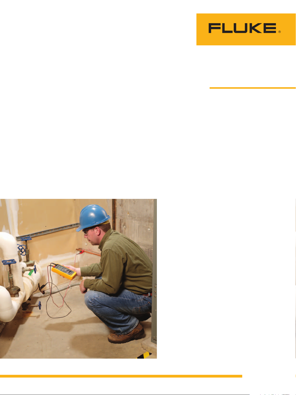
The Fluke 1621 Earth Ground Tester is an easy-to-use earth ground tester,
the first line of defense in detecting reliable ground connections.
From the Fluke Digital Library @ www.fluke.com/library
Page 2
Grounding connections
A premises wiring system supplied by a grounded ac service
must have a grounding electrode
conductor connected to the
grounding service conductor.
The connection must be made
at an accessible point from the
load end of the service drop or
service lateral to the terminal or
bus to which the grounded service conductor is connected at
the service disconnect. Service
drop refers to overhead conductors; service lateral refers to
underground conductors.
If the transformer supplying
the service is located outside the
building, at least one additional
grounding connection must
be made from the grounded
service conductor to a grounding
electrode—either at the transformer or elsewhere outside the
building. For services that are
dual fed in a common enclosure
or grouped together in separate
enclosures and use a secondary
tie, a single grounding electrode
conductor connection to the tie
point of the grounded conductors from each power source is
allowed.
While earth grounding
involves an intentional connection from a circuit or system
conductor to a ground electrode
placed in the earth, equipment
grounding connects the equipment housing or cabinet to a
grounding electrode. This circuit
or system conductor typically
refers to the neutral conductor.
Article 250.26 of the NEC specifies which conductor is to be
grounded for ac premises wiring
systems:
System wiring configuration Conductor to be grounded
Single-phase, 2-wire One conductor
Single-phase, 3-wire Neutral conductor
Multi-phase systems with one
wire common to all phases
Multi-phase systems where one
phase is grounded
Multi-phase systems in which
one phase is used as in the
single-phase, 3-wire system
Common conductor
One phase conductor
Neutral conductor
Exposed, normally noncurrent-carrying metal parts of
fixed equipment supplied by or
enclosing conductors or components that are likely to become
energized must be connected
to an equipment grounding conductor if the operating
equipment:
• Has any terminals with more
than 150 V to ground.
• Is located in a wet or damp
area and not electrically
isolated.
• Is subject to human contact.
• Is supplied by a wiring
method that provides an
equipment grounding
conductor.
Earth ground
Properly grounding a facility’s
electrical system ensures a low
impedance connection from the
electrical system to the earth.
However, the effectiveness
of the earth ground depends
on several factors. While the
ground electrode placed into the
earth should be highly conductive, actual ground resistance
depends on the length and
depth of the ground electrode
placed into the earth, the
diameter of the electrode, the
actual number of electrodes, the
grounding system design, and
the actual resistivity—or conductivity—of the soil.
The degree to which soil conducts electricity is both variable
and complex. Soil depth affects
resistivity, which typically
decreases as depth increases.
Deep electrode placement can
reduce earth ground impedance,
as can using multiple electrodes.
Other factors affecting soil resistivity include soil composition,
mineral content, settling and/or
compression, temperature (resistivity increases as temperature
decreases), and the presence (or
absence) of metal objects buried
in the soil (such as tanks or
pipes).
Because grounding electrodes
are subject to oxidation and
corrosion and because of the
potential for soil resistivity to
vary, the integrity of the ground
electrode should be tested
periodically. Earth grounding
systems can be tested using
earth ground testers such as
models 1621, 1625/1623, and
1630 available from Fluke.
Earth ground testers measure
ground resistivity by applying
a voltage to
the electrode
and measuring
the resulting
current. Fluke
offers a great
deal of information about earth
ground testing
on its website.
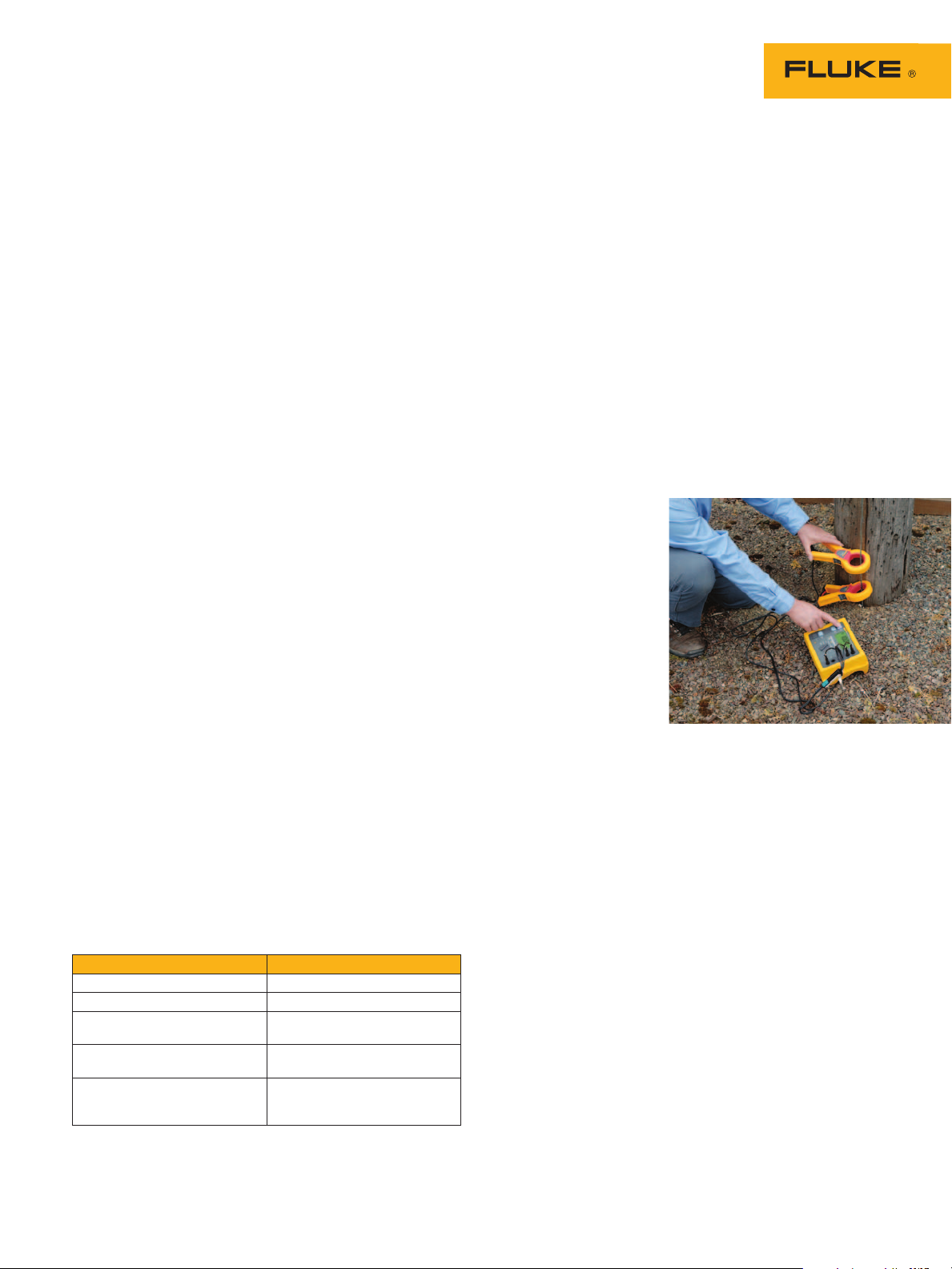
With the Fluke 1625 GEO Earth Ground Tester you can perform
3- and 4-pole earth ground measurement, 4-pole soil resistivity
testing, 2-pole resistance measurement ac, 2- and 4-pole resistance
measurement dc, selective testing, and stakeless testing.
Fluke. The Most Trusted Tools
in the World.
Fluke Corporation
PO Box 9090, Everett, WA 98206 U.S.A.
Fluke Europe B.V.
PO Box 1186, 5602 BD
Eindhoven, The Netherlands
For more information call:
In the U.S.A. (800) 443-5853 or
Fax (425) 446-5116
In Europe/M-East/Africa +31 (0) 40 2675 200 or
Fax +31 (0) 40 2675 222
In Canada (800)-36-FLUKE or
Fax (905) 890-6866
From other countries +1 (425) 446-5500 or
Fax +1 (425) 446-5116
Web access: http://www.fluke.com
©2012 Fluke Corporation.
Specifications subject to change without notice.
Printed in U.S.A. 6/2012 4236260A_EN
Modification of this document is not permitted
without written permission from Fluke Corporation.
2 Fluke Corporation Temperature and vibration send maintenance signals
 Loading...