

Page 1

1623-2
Earth/Ground Tester
January 2014
© 2014 Fluke Corporation. All rights reserved. Specifications are subject to change without notice.
All product names are trademarks of their respective companies.
Users Manual
Page 2

LIMITED WARRANTY AND LIMITATION OF LIABILITY
Each Fluke product is warranted to be free from defects in material and workmanship under normal use and
service. The warranty period is two years and begins on the date of shipment. Parts, product repairs, and
services are warranted for 90 days. This warranty extends only to the original buyer or end-user customer of
a Fluke authorized reseller, and does not apply to fuses, disposable batteries, or to any product which, in
Fluke's opinion, has been misused, altered, neglected, contaminated, or damaged by accident or abnormal
conditions of operation or handling. Fluke warrants that software will operate substantially in accordance
with its functional specifications for 90 days and that it has been properly recorded on non-defective media.
Fluke does not warrant that software will be error free or operate without interruption.
Fluke authorized resellers shall extend this warranty on new and unused products to end-user customers
only but have no authority to extend a greater or different warranty on behalf of Fluke. Warranty support is
available only if product is purchased through a Fluke authorized sales outlet or Buyer has paid the
applicable international price. Fluke reserves the right to invoice Buyer for importation costs of
repair/replacement parts when product purchased in one country is submitted for repair in another country.
Fluke's warranty obligation is limited, at Fluke's option, to refund of the purchase price, free of charge repair,
or replacement of a defective product which is returned to a Fluke authorized service center within the
warranty period.
To obtain warranty service, contact your nearest Fluke authorized service center to obtain return
authorization information, then send the product to that service center, with a description of the difficulty,
postage and insurance prepaid (FOB Destination). Fluke assumes no risk for damage in transit. Following
warranty repair, the product will be returned to Buyer, transportation prepaid (FOB Destination). If Fluke
determines that failure was caused by neglect, misuse, contamination, alteration, accident, or abnormal
condition of operation or handling, including overvoltage failures caused by use outside the product’s
specified rating, or normal wear and tear of mechanical components, Fluke will provide an estimate of repair
costs and obtain authorization before commencing the work. Following repair, the product will be returned to
the Buyer transportation prepaid and the Buyer will be billed for the repair and return transportation charges
(FOB Shipping Point).
THIS WARRANTY IS BUYER'S SOLE AND EXCLUSIVE REMEDY AND IS IN LIEU OF ALL OTHER
WARRANTIES, EXPRESS OR IMPLIED, INCLUDING BUT NOT LIMITED TO ANY IMPLIED WARRANTY
OF MERCHANTABILITY OR FITNESS FOR A PARTICULAR PURPOSE. FLUKE SHALL NOT BE LIABLE
FOR ANY SPECIAL, INDIRECT, INCIDENTAL OR CONSEQUENTIAL DAMAGES OR LOSSES,
INCLUDING LOSS OF DATA, ARISING FROM ANY CAUSE OR THEORY.
Since some countries or states do not allow limitation of the term of an implied warranty, or exclusion or
limitation of incidental or consequential damages, the limitations and exclusions of this warranty may not
apply to every buyer. If any provision of this Warranty is held invalid or unenforceable by a court or other
decision-maker of competent jurisdiction, such holding will not affect the validity or enforceability of any other
provision.
Fluke Corporation
P.O. Box 9090
Everett, WA 98206-9090
U.S.A.
Fluke Europe B.V.
P.O. Box 1186
5602 BD Eindhoven
The Netherlands
11/99
To register your product online, visit register.fluke.com.
Page 3

Table of Contents
Title Page
Introduction ........................................................................................................ 1
How to Contact Fluke ......................................................................................... 1
Safety Information .............................................................................................. 2
Storage ............................................................................................................... 3
Models and Accessories .................................................................................... 4
Additional Accessories ....................................................................................... 5
Features ............................................................................................................. 6
Display ............................................................................................................... 7
Setup .................................................................................................................. 8
Batteries ......................................................................................................... 8
Description of Functions ................................................................................ 10
Operation ........................................................................................................... 11
RA 2-Pole, 3-Pole Measurements .................................................................. 11
RA 4-Pole Measurements .............................................................................. 13
RA 3-Pole Selective Earth Resistance Measurement with Current Clamp .... 15
RA 4-Pole Selective Earth Resistance Measurement with Current Clamp .... 17
Stakeless Ground Loop Measurement .......................................................... 19
Advanced Operation .......................................................................................... 21
Measurements on High Voltage Pylons ........................................................ 21
Measurement of Soil Resistivity .................................................................... 24
Export Stored Data to PC .................................................................................. 26
Delete Stored Data ............................................................................................. 26
How to Troubleshoot .......................................................................................... 27
Maintenance ....................................................................................................... 29
Calibration .......................................................................................................... 29
Service ............................................................................................................... 29
Specifications ..................................................................................................... 30
i
Page 4

1623-2
Users Manual
ii
Page 5

List of Tables
Table Title Page
1. Symbols .................................................................................................................. 3
2. Models and Accessories ........................................................................................ 4
3. Features and Functions .......................................................................................... 6
4. Display .................................................................................................................... 7
5. Sample .CSV File for Logged Data ........................................................................ 26
6. Troubleshooting ...................................................................................................... 27
iii
Page 6

1623-2
Users Manual
iv
Page 7

List of Figures
Figure Title Page
1. External Current Transformer EI-162BN ................................................................ 5
2. Battery Insertion ..................................................................................................... 9
3. R
4. R
5. R
6. R
7. R
8. Stakeless Ground Loop Measurement ................................................................... 20
9. Earthing Resistance without Disengaging the Overhead Earth Wire ..................... 21
10. Measurement of Soil Resistivity ............................................................................. 24
11. Troubleshooting ...................................................................................................... 28
2-Pole Measurement ......................................................................................... 12
A
3-Pole Measurement ......................................................................................... 12
A
4-Pole Measurements ....................................................................................... 14
A
3-Pole Selective Earth Resistance Measurement with Current Clamp ............. 16
A
4-Pole Selective Earth Resistance with Current Clamp .................................... 18
A
v
Page 8

1623-2
Users Manual
vi
Page 9

Introduction
The 1623-2 Earth Ground Tester (Tester or Product) is a compact, field-rugged
instrument that performs all four types of earth ground measurement. Specifically, the
Tester is able to measure earth ground loop resistances using only clamps – called
Stakeless testing. This method doesn’t require the use of earth ground stakes or the
disconnection of ground rods.
The 1623-2 features:
• One-button measurement concept
• 3-pole and 4-pole earth ground measurement
• 4-pole soil resistivity testing
• Selective testing, no disconnection of ground conductor (1 clamp)
• Stakeless testing, quick ground loop testing (2 clamps)
• Measuring frequency 128 Hz
How to Contact Fluke
To contact Fluke, use one of these telephone numbers:
• USA: 1-800-760-4523
• Canada: 1-800-36-FLUKE (1-800-363-5853)
• Europe: +31 402-675-200
• Japan: +81-3-6714-3114
• Singapore: +65-6799-5566
• Anywhere in the world: +1-425-446-5500
Go to www.fluke.com to register your product, download manuals, and find more
information.
To view, print, or download the latest manual supplement, visit
http://us.fluke.com/usen/support/manuals.
1
Page 10

1623-2
Users Manual
Safety Information
A Warning identifies hazardous conditions and procedures that are dangerous to the
user. A Caution identifies conditions and procedures that can cause damage to the
Product or the equipment under test.
Warning
To prevent possible electrical shock, fire, or personal injury:
• Read all safety information before you use the Product.
• Use the Product only as specified, or the protection supplied by
the Product can be compromised.
• Do not use the Product if it operates incorrectly.
• Do not use the Product if it is damaged.
• Do not use test leads if they are damaged. Examine the test leads
for damaged insulation, exposed metal, or if the wear indicator
shows. Check test lead continuity.
• Do not use the Product around explosive gas, vapor, or in damp or
wet environments.
• Do not apply more than the rated voltage, between the terminals or
between each terminal and earth ground.
• Use only current probes, test leads, and adapters supplied with the
Product.
• Do not use a current measurement as an indication that a circuit is
safe to touch. A voltage measurement is necessary to know if a
circuit is hazardous.
• The battery door must be closed and locked before you operate the
Product.
• Replace the batteries when the low battery indicator shows to
prevent incorrect measurements.
• Do not connect directly to mains.
• Do not touch voltages >30 V ac rms, 42 V ac peak, or 60 V dc.
2
Page 11
Earth/Ground Tester
Storage
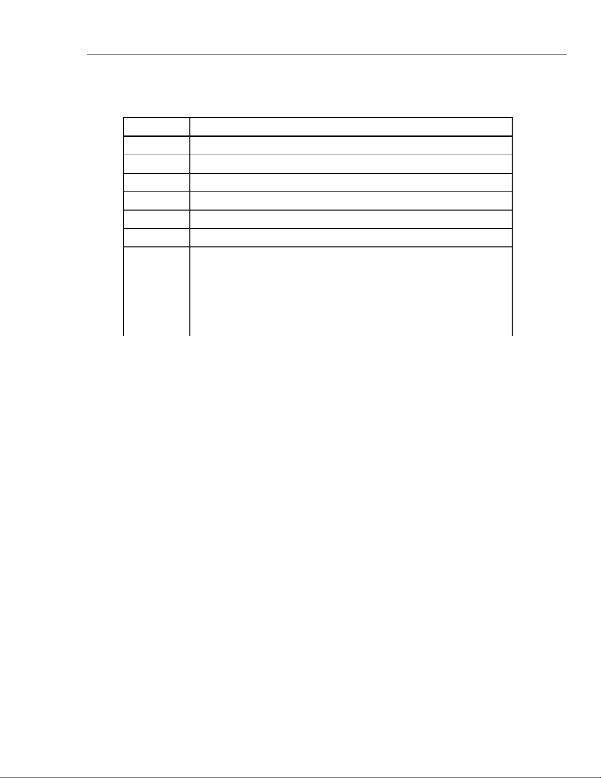
Table 1 is a list of symbols used on the Tester and in this manual.
Table 1. Symbols
Symbol Description
Risk of Danger. Important information. See Manual.
Hazardous voltage. Risk of electrical shock.
Battery Indicator
Conforms to European Union directives.
Conforms to relevant South Korean EMC Standards.
Conforms to relevant Australian EMC requirements.
This product complies with the WEEE Directive (2002/96/EC) marking
requirements. The affixed label indicates that you must not discard this
electrical/electronic product in domestic household waste. Product Category:
With reference to the equipment types in the WEEE Directive Annex I, this
product is classed as category 9 "Monitoring and Control Instrumentation”
product. Do not dispose of this product as unsorted municipal waste. Go to
Fluke’s website for recycling information.
Storage
If the Tester is stored for an extended period of time or is not in use for a long time, you
should remove the batteries.
3
Page 12

1623-2
Users Manual
Models and Accessories
These standard accessories were shipped with your Tester:
• 6 alkaline AA – type (LR6) batteries
• 2 measuring leads 1.5 m
• 1 connector cable (for RA 2-pole measurements)
• 2 alligator clips
• 1 Documentation CD with Users Manual
• Quick Reference Guide
• Safety Information
Table 2 lists the models and accessories.
Table 2. Models and Accessories
Description Part Number
1623-2 Earth Ground Tester
(Includes Users Manual, Safety Information, QRG, Geox Probe
Cable, 2 clips, Lead set) 4325155
1623-2 Earth Ground Tester Kit
(Includes Users Manual, Safety Information, QRG, Geox Probe
Cable, 2 clips, Lead set, 4 Earth Stakes, 3 Cable Reels, C1620
Carrying Case, EI-162X & EI-162AC) 4325170
162x-7001 Service Replacement Kit
(Includes Lead set & 2 clips) 2577167
Earth Stake 4325492
ES-162P3-2 Stake Set for 3 Pole Measurement
(Includes 3 Earth Stakes, 1 Cable Reel 25M Blue, 1 Cable Reel 50M
Red) 4359377
ES-162P4-2 Stake Set for 4 Pole Measurement
(Includes 4 Earth Stakes, 1 Cable Reel 25M Blue, 1 Cable Reel 25M
Green, 1 Cable Reel 50M Red) 4359389
EI-1623 Selective/Stakeless Clamp Set for 1623-2/1625-2
(Includes EI-162X, EI-162AC) 2577115
EI-162X Clip-on Current Transformer (sensing) with shielded cable
set 2577132
EI-162AC Clip-on Current Transformer (inducing) 2577144
EI-162BN Split Core Transformer - for Pylon Testing
(12.7 inch - 320 mm) 2577159
Shielded Cable (Used w/ EI-162X Clamp) 2630254
4
Cable Reel, 25M, Blue wire 4343731
Cable Reel, 25M, Green wire 4343746
Cable Reel, 50M, Red wire 4343754
C1620 Carrying Case 4359042
Page 13

Earth/Ground Tester
Additional Accessories
Additional Accessories
An external current transformer is available as an option, see Figure 1. The
transformer has a transformation ratio between 80 and 1200:1 for the measurement of a
single branch in mesh-operated earthing systems. This enables the user to measure on
high voltage pylons without separating the overhead earth wires or earth strips at the
bottom of the pylons. It is also used to measure lightning protection systems without
separating the individual lightning protection wires.
1
3
NORMA
1000
500
A 6805 06211
200
!
2
Figure 1. External Current Transformer EI-162BN
Transformer half (2)
Transformer end faces have bolts that pivot to aid in separating the Transformer
halves. One Transformer end face has a slotted bolt hole that allows the bolt to
pivot out of the end face.
Transformation ratio connections: ⊥, 200, 500, and 1000
Fastener (2)
evx01.eps
5
Page 14

1623-2
Users Manual
Features
Typical applications for the Tester include:
• Earth/ground resistance measurements in different installations, such as, high
voltage pylons, buildings, electrical service grounding systems, mobile
communication stations, and HF transmitters.
• Monitor and plan lightning protection systems
• Resistance measurements with earth electrodes; no separation
See Table 3 for a list of features and functions.
Table 3. Features and Functions
3
2
1
1623-2 EARTH/GROUND TESTER
11
9 10
4
5
6
7
8
edv001.eps
Item Description
Rotary switch to select measurement function and ON/OFF
“START” button to start the selected measurement function
6
Liquid crystal display (LCD)
Connection “H/C2” for auxiliary earth (4 mm ∅)
Connection “S/P2” for probe (4 mm ∅)
Connection for sense current test clamp
Connection “ES/P1” for earth electrode probe (4 mm ∅)
Connection “E/C1” for the earth/ground electrode to be measured (4 mm ∅)
Battery compartment for 6 alkaline batteries (type AA, LR6)
Screws to fasten the battery compartment
USB Type B Port
Page 15

Earth/Ground Tester
Display
Display
The LCD is a 1999-digit display with special symbols and digit height of 25 mm. See
Table 4 for location and description of each display element.
Table 4. Display
1
11
10
2
3
4
5
6
789
edv009.eps
Item Description
Measurement value
Measurement in process
Measurement complete
Connection for current clamp
Measurement unit
Socket indicator
Battery voltage too low, replace batteries
Current clamp socket indicator
Error
External voltage too high/External current
RH>Limit: Auxiliary Earth electrode resistance too high
RS>Limit: Probe resistance too high
7
Page 16

1623-2
Users Manual
Setup
Warning
Read the safety information before you power on the instrument. If
you have problems, see How to Troubleshoot.
Batteries
Warning
To prevent possible electrical shock, fire, or personal injury:
• The battery door must be closed and locked before you operate
the Product.
• Replace the batteries when the low battery indicator shows to
prevent incorrect measurements.
• Batteries contain hazardous chemicals that can cause burns or
explode. If exposure to chemicals occurs, clean with water and get
medical aid.
Warning
For safe operation and maintenance of the Product:
• Repair the Product before use if the battery leaks.
• Be sure that the battery polarity is correct to prevent battery
leakage.
To insert the batteries:
1. Switch off instrument, see Figure 2.
2. Disconnect all test leads.
3. Open battery compartment.
4. Insert batteries. Always replace the complete set of batteries.
5. Close battery compartment.
8
Page 17

Earth/Ground Tester
Setup
1 2
1623-2 EARTH/GROUND TESTER
3 4
Figure 2. Battery Insertion
+
edv002.eps
9
Page 18

1623-2
Users Manual
Description of Functions
The functions are selected with the central rotary switch. Measurement values are shown
on a liquid crystal display with correct decimal point and unit. Additional special
characters indicate measurement mode, operating condition, and error messages.
The Tester includes these measurement functions:
• Earthing Resistance (RE) The earthing resistance is determined by a 3-pole or
4-pole current and voltage measurement. The
measuring voltage is a square pulse ac voltage with
48 / 20 V and a frequency of 94, 105, 111 or 128 Hz.
The frequency can be selected manually or
automatically (AFC).
• Selective Measurement of
Earthing (R
• Low Battery Indicator Battery voltage is low, replace batteries.
)
E
Measurement of a single earth electrode in a mesh
operated (parallel) earthing system. The current flowing
through the single earth electrode is measured with an
external current transformer.
10
Page 19

Earth/Ground Tester
Operation
Operation
The Tester is equipped with a 3-pole as well as a 4-pole resistance measurement that
renders measurements of resistances of earthing systems and measurements of the soil
resistivity of geological strata. The Tester also makes measurements with an external
current transformer, with which a measurement of single resistance branches in
interlinked networks (lightning protection and high voltage pylons with cabling) can be
performed without separating parts of the system.
RA 2-Pole, 3-Pole Measurements
To make 2-pole or dead-earth measurements, connect a jumper between terminals H/C2
and S/P2 with the supplied connector cable. Use only the earth electrode and the
auxiliary earth electrode. Minimum distance between earth electrode (E/CD1) and
auxiliary earth (H/C2) should be at least 20 m.
See Figures 3 and 4 and do steps 1 thru 4:
1. Select 3 POLE.
2. Connect the test leads.
Connect terminal E/C1 to the earth/ground system to be measured with the
supplied test lead and clip (1.5 m). Place two ground stakes in earth/dirt.
Note
Minimum distance between earth electrode (E/C1), probe
(S/P2), and auxiliary earth (H/C2) should be at least 20 m.
Connect the stakes with the 25 m and 50 m cable reels to H/C2 and S/P2 as
shown in Figures 3 and 4.
3. Push START.
indicates that a measurement is in progress. For a continuous
measurement, continue to push the START button.
4. indicates a completed measurement. The result is kept on the display until a
new measurement is started or the main switch is turned.
11
Page 20

1623-2
Users Manual
1 2
1623-2 EARTH/GROUND TESTER
H/C2E/C1
>20 m
3 4
START
Figure 3. RA 2-Pole Measurement
1 2
1623-2 EARTH/GROUND TESTER
3 4
START
>20 m
S/P2
>20 m
edv003.eps
H/C2E/C1
12
Figure 4. RA 3-Pole Measurement
edv003b.eps
Page 21

Earth/Ground Tester
Operation
RA 4-Pole Measurements
To make 4-pole measurements:
1. Select 4 POLE function. See Figure 5.
2. Connect test leads.
Connect terminals E/C1 and ES/P1 to the earth system to be measured with the
two supplied test leads (1.5 m). Place two ground stakes in earth/dirt. Minimum
distance between earth electrode (E/C1), probe (S/P2), and auxiliary earth (H/C2)
should be at least 20 m. The ES test lead eliminates the influence of the test
leads.
Connect the stakes with the 25 m and 50 m cable reels to H/C2 and S/P2 as
shown below.
3. Push START.
indicates that a measurement is in progress. For a continuous
measurement, continue to push the START button.
4. indicates a completed measurement. The result is kept on the display until a
new measurement is started or the rotary switch is turned.
13
Page 22

1623-2
Users Manual
1 2
1623-2 EARTH/GROUND TESTER
3 4
START
Figure 5. RA 4-Pole Measurements
ES/P1
E/C1
>20 m
S/P2
>20 m
H/C2
edv004.eps
14
Page 23

Earth/Ground Tester
Operation
RA 3-Pole Selective Earth Resistance Measurement with Current Clamp
The RA 3-pole Selective Earth Resistance Measurement with Current Clamp procedure is
useful for the resistance measurement of different parallel sections of an earth/ground
system.
Select 3 POLE . See Figure 6.
1.
2.
Connect test leads.
Connect the supplied test lead (1.5 m) to terminal E/C1 and its other end to the
ground system to be measured. Place two ground stakes in earth/dirt. Minimum
distance between earth electrode (E/C1), probe (S/P2) and auxiliary earth (H/C2)
should be at least 20 m.
Connect stakes with 25 m and 50 m wires to H/C2 and S/P2 as shown.
Connect current clamp with adapter cable as shown.
3.
Push START.
indicates that measurement is in progress. For continuous
measurement, continue to push the START button.
4. indicates completed measurement. The result is kept on display until a new
measurement is started or the rotary switch is turned.
15
Page 24

1623-2
Users Manual
1 2
1623-2 EARTH/GROUND TESTER
3 4
START
Figure 6. RA 3-Pole Selective Earth Resistance Measurement with Current Clamp
E/C1
>20 m
S/P2
E
>20 m
HS
H/C2
edv005.eps
16
Page 25

Earth/Ground Tester
Operation
RA 4-Pole Selective Earth Resistance Measurement with Current Clamp
The RA 4-pole Selective Earth Resistance Measurement with Current Clamp procedure is
useful for the resistance measurement of different parallel sections of an earth/ground
system.
Select function 4 POLE . See Figure 7.
1.
Connect test leads.
2.
Connect terminals E/C1 and ES/P1 with the supplied safety test leads (1.5 m) to
the earth electrode to be measured. Place two ground stakes in earth/dirt.
Minimum distance between earth electrode (E/C1), probe (S/P2) and auxiliary
earth (H/C2) should be a minimum 20 m. The test lead eliminates the influence
of the test leads.
Connect stakes with 25 m and 50 m wires to H/C2 and S/P2 as shown.
Connect current clamp with adapter cable as shown.
Push START.
3.
indicates that measurement is in progress. For continuous
measurement, continue to push the START button.
indicates completed measurement. The result is kept on display until a new
4.
measurement is started or the rotary switch is turned.
17
Page 26

1623-2
Users Manual
1 2
1623-2 EARTH/GROUND TESTER
ES/P1
E/C1
3 4
START
Figure 7. RA 4-Pole Selective Earth Resistance Measurement with Current Clamp
E/C1
>20 m
S/P2
>20 m
H/C2
edv006.eps
18
Page 27

Earth/Ground Tester
Operation
Stakeless Ground Loop Measurement
With this test method, two clamps are placed around the earth ground rod or the
connecting cable and each are connected to the Tester. Earth ground stakes are not
used. A known voltage is induced by one clamp, and the current is measured with the
second clamp. The tester automatically determines the ground loop resistance at this
ground rod.
1. Select
2. Connect current clamps.
Connect the inducing clamp (see Models and Accessories) to terminals H/C2 and
E/C1 with the supplied safety test leads (1.5 m) as shown.
Connect the second current clamp using the adapter cable (sensing current
clamp).
Clamp both current clamps around the earth electrode, which will subsequently be
measured.
3. Push START.
indicates that measurement is in progress. For continuous
measurement, continue to push the START button.
. See Figure 8.
Note
Use the recommended current clamp for inducing only.
Other current clamps are not suited.
Note
Minimum distance between the two current clamps is
10 cm.
4. indicates completed measurement. The result is kept on display until a new
measurement is started or the rotary switch is turned.
19
Page 28

1623-2
Users Manual
1 2
1623-2 EARTH/GROUND TESTER
≥10 cm
3 4
START
Figure 8. Stakeless Ground Loop Measurement
edv007.eps
20
Page 29

Earth/Ground Tester
Advanced Operation
Advanced Operation
The Tester uses advanced features to measure earth resistance of a single high voltage
pylon and soil resistivity for calculation and design of earthing systems.
Measurements on High Voltage Pylons
The measurement of the earth resistance of a single high voltage pylon usually requires
the overhead earth wire to be disengaged (lifted off) or the separation of the earthing
system from the pylon construction. Otherwise, false reading of the resistance of the
pylon earth electrode are liable to occur because of the parallel circuit of the other pylons
connected to each other by an overhead earth wire.
The new measuring method employed in this instrument - with its external current
transformer to measure the true current flowing through the earth electrode - allows
measurements of earth electrode resistances without disconnection of the earthing
system or disengaging the overhead earth wire. See Figure 9.
1 2
1623-2 EARTH/GROUND TESTER
3 4
START
Figure 9. Earthing Resistance without Disengaging the Overhead Earth Wire
4 Probe
S/P2 H/C2
>20 m>20 m
edv016.eps
21
Page 30

1623-2
Users Manual
As all four pylon stubs are connected to the foundation earth of the pylon, the measuring
current I
is divided into five components according to the present resistances
meas
involved.
One part flows via pylon construction to the overhead earth wire and further to the
parallel circuited pylon earthing resistances.
The other four current components (I
The addition of all currents result in a current I
... I4) flow via the individual pylon foots.
1
going through the earthing resistance, for
E
example, the resistance of the "composite" earth electrode to the soil.
If the current transformer is fixed to each pylon stub, one after the other, four resistances
have to be measured which show a behavior inversely proportional to the corresponding
current components I
... I4. The feeding point of the measuring current is to be left
1
unchanged to avoid a change in the current distribution.
Accordingly, these equivalent resistances are displayed as:
U
meas
=
R
Ei
Therefore the earthing resistance R
li
of the pylon is determined as a parallel circuit of the
E
individual equivalent resistances:
R
=
E
1
+++
1. Turn central rotary switch to position “R
1111
RRRR
4321
EEEE
3pole" or RE 4pole". The instrument
E
is to be wired according to picture and messages on the display.
2. Apply current transformer to the pylon stub.
3. Push START.
Now a fully automated test sequence of all relevant parameters like auxiliary earth
electrode, probe and earth electrode resistances is implemented and finishes with the
display of the result R
.
E
22
Page 31

Earth/Ground Tester
Advanced Operation
4. Read out measured value R
.
E
Note
Before setting the earth stakes for probe and auxiliary earth electrode make
sure that the probe is set outside the potential gradient of earth electrode
and auxiliary earth electrode. Such a condition is normally reached by
allowing a distance of >20 m between the earth electrode and the earth
stakes as well as to the earth stakes to each other. An accuracy test of the
results is made with another measurement after repositioning of auxiliary
earth electrode or probe. If the result is the same, the distance is sufficient.
If the measured value changes, probe or auxiliary earth electrode must be
repositioned until the measured value R
remains constant.
E
Stake wires should not run too close.
5. Apply current transformer to next pylon stub.
6. Repeat measuring sequence.
Current feeding point of measuring current (alligator clip) and the polarity of the split
core current transformer has to be left unchanged.
After values of R
of all pylon foots are determined, the actual earth resistance RE
Ei
has to be calculated:
R
=
E
1
+++
1111
RRRR
4321
EEEE
Note
If the displayed R
value is negative despite correct orientation of the
E
current transformer, a part of the measuring current is flowing upwards into
the tower body. The earthing resistance, thus coming into effect, correctly
calculates if the individual equivalent resistances (under observation of their
polarity) are inserted into the equation above.
23
Page 32

1623-2
Users Manual
Measurement of Soil Resistivity
The soil resistivity is the geological and physical quantity for calculation and design of
earthing systems. The measuring procedure shown in Figure 10 uses the method
developed by Wenner (F. Wenner, A method of measuring earth resistivity; Bull. National
Bureau of Standards, Bulletin 12 (4), Paper 258, S 478-496; 1915/16).
1623-2 EARTH/GROUND TESTER
Figure 10. Measurement of Soil Resistivity
edv020.eps
1. Four earth stakes of the same length are positioned into the soil in an even line and
with the same distance "a" to each other. The earth stakes should not be hammered
in deeper than a maximum of 1/3 of "a".
2. Turn central rotary switch to position "R
4pole".
E
The instrument is to be wired according to picture and notices given on the display.
3. Push START.
4. Read out measured value R
.
E
24
Page 33

Earth/Ground Tester
π
ρ
Advanced Operation
From the indicated resistance value R
, the soil resistivity calculates according to the
E
equation:
=
ρ
...... mean value of soil resistivity (Ωm)
E
R
...... measured resistance (Ω)
E
Ra..2
EE
a ...... probe distance (m)
The measuring method according to Wenner determines the soil resistivity down to a
depth of approx. the distance "a" between two earth stakes. By increasing "a", deeper
strata can be measured and checked for homogeneity. By changing "a" several times, a
profile can be measured from which a suitable earth electrode can be determined.
According to the depth to be measured, "a" is selected between 2 m and 30 m. This
procedure results in curves depicted in the graph below.
2
1
3
Soil restivity ρE
A
Distances of Probe
edw021.eps
Curve 1: As ρE decreases only deeper down, a deep earth electrode is advisable
Curve 2: As ρE decreases only down to point A, an increase in the depth deeper
than A does not improve the values.
25
Page 34

1623-2
Users Manual
Curve 3: With increasing depth ρE is not decreasing: a strip conductor electrode is
advisable.
As measuring results are often distorted and corrupted, for example, by
underground pieces of metal and underground aquifers, a second
measurement, in which the stake axis is turned by an angle of 90 °, is
always advisable (see graph below).
90°
E
ES
S
H
I
edw022.eps
Export Stored Data to PC
Test data is automatically stored for all tests as a .csv file. Table 5 is an example of the
.csv file.
To export data from the Tester to a PC:
1. Connect the USB cable from the Tester to the PC.
2. Use Windows Explorer on the PC to find new EGT drive in the Devices list.
3. Locate the Data.csv file on the EGT drive.
4. Use the standard PC tools to copy the file to a new location.
Table 5. Sample .CSV File for Logged Data
Measurement Timestamp
1 15th Oct 2013 20:13:55 3-pole RE 1.022 Ω NA
2 15th Oct 2013 20:13:55 4-pole RE 1.022 Ω NA
3 15th Oct 2013 20:13:55 3-pole Selective 1.022 Ω NA
4 15th Oct 2013 20:13:55 4-pole RE NA Rh Limit
Measurement
Mode
Earth Ground
Resistance R
Error
Status
E
26
Delete Stored Data
To delete stored data in the Tester:
1. Connect the USB cable from the Tester to the PC.
2. Use Windows Explorer on the PC to find new EGT drive in the Devices list.
3. Locate the Data.csv file on the EGT drive.
4. Use the standard PC tools to delete the file from the EGT drive or move the file to a
new location.
This action removes all stored date from the Tester.
Page 35

Earth/Ground Tester
How to Troubleshoot
How to Troubleshoot
Follow the steps in Table 6. See Figure 11 for steps 1-5.
Table 6. Troubleshooting
Step Description
1. External voltage (Uext) too high
If the external voltage applied to the instrument is too high, usually from leakage currents in the
system under test, no measurement can be started (see Specifications for Uext limit).
Hint: Reposition probe (S/P2) and restart measurement.
2. Auxiliary earth electrode resistance (RH) too high
If the auxiliary earth electrode resistance is too high it is not possible to drive the current
necessary for reliable measurements. The measurement is blocked (see Specifications for Rh
limit).
Hint: Check connection of test lead with terminal H/C2, check auxiliary earth stake.
Probe resistance (Rs) too high
3.
If the probe resistance is too high measurements are not reliable. The measurement is blocked
(see Specifications for Rs limit).
Hint: Check connection of test lead with terminal S/P2, check probe stake.
Weak batteries
4.
If the batteries are weak, the supply voltage may break down during measurement. If there is
enough energy to complete the measurement “
are valid. If not, a reset occurs.
Hint: Replace batteries. Use 6 alkaline AA-type (LR6) batteries.
Is your R
5.
Probe S/P2 must be outside the potential gradient areas of E/C1 and H/C2 for accurate
measurements. Normally a probe distance of more than 20 m is sufficient. However, in some
environmental conditions where the soil resistivity is variable, this may not be sufficient. To be
sure, reposition the probes and take several measurements. If the readings are approximately
the same, your measurement results are reliable. If not, increase the probe distance.
Is the result of a “Stakeless ground loop measurement” reliable?
6.
Ensure that you have the correct inducing clamp (see Accessories).
The clamp parameters are suited for this test method. An undefined clamp will give incorrect
results.
Ensure that the recommended minimum distance between the current clamp is kept. If the
clamps are positioned too close together, the magnetic field of the inducing clamp will influence
the sensing current clamp. To avoid mutual influencing, the distance between the clamps can be
varied and a new test performed. If the measurement values vary only a little or not at all, the
value can be regarded as reliable.
measurement result reliable?
A
” symbol is displayed – measurement results
27
Page 36

1623-2
Users Manual
1
5
2
S/P2
H/C2E/C1
3
Us
>20 m
Ug
>20 m
4
Figure 11. Troubleshooting
edv008.eps
28
Page 37

Earth/Ground Tester
Maintenance
Maintenance
If used and treated properly, the instrument needs no maintenance. To clean the
instrument, use only a moist cloth with some soap water or soft household detergent or
spirit. Avoid aggressive cleaning agents and solvents, such as trilene or chlorothene.
Service work must only be undertaken by trained qualified staff.
In all repair work care must be taken that the design parameters of the instrument are not
modified to the detriment of safety, that assembled parts correspond to the original
spares and that they are reassembled properly (factory state).
Warning
To prevent possible electrical shock, fire, or personal injury:
• Use only specified replacement parts.
• Have an approved technician repair the Product.
• The battery door must be closed and locked before you operate
the Product.
• Replace the batteries when the low battery indicator shows to
prevent incorrect measurements.
• Batteries contain hazardous chemicals that can cause burns or
explode. If exposure to chemicals occurs, clean with water and get
medical aid.
• Remove the input signals before you clean the Product.
For safe operation and maintenance of the Product:
• Repair the Product before use if the battery leaks.
• Be sure that the battery polarity is correct to prevent battery
leakage.
Calibration
One-year calibration intervals are recommended.
Service
If you suspect that the Tester has failed, review this manual to make sure you are
operating it correctly. If the meter still fails to operate properly, pack it securely (in its
original container if available) and forward it, postage paid, to the nearest Fluke Service
Center. Include a brief description of the problem. Fluke assumes NO responsibility for
damage in transit.
To locate an authorized service center, go to www.fluke.com.
Warning
29
Page 38

1623-2
Users Manual
Specifications
Temperature ranges
Operating temperature range: 0 °C to +35 °C (+32 °F to +95 °F)
Storage temperature range: -20 °C to +60 °C (-4 °F to +140 °F)
Temperature coefficient: ±0.1 % of rdg / °C (below 18 °C and above 28 °C)
Operating humidity: <95 % RH noncondensing
Operating altitude: 2000 m
Climatic class: C1 (IEC 654-1), -5 °C to +45 °C, 5 % to 95 % RH
Protection type
Case: IP56
Battery door: IP40
Electromagnetic compatibility: Complies with IEC61326-1: Portable
Safety: Complies with IEC 61010-1: CAT None, Pollution Degree 2
External voltage: U
Noise rejection: >120 dB (162/3, 50, 60, 400 Hz)
Measurement time: 6 seconds, typical
Maximum overload: 250 V
Batteries: 6 x 1.5 v, AA, LR6 Alkaline
Battery life span: >3000 measurements, typical
Dimensions: 240 mm x 180 mm x 110 mm (9.5 in x 7.1 in x 4.4 in)
Weight with batteries: 1.49 kg (3.28 lb)
Memory: Internal memory storage up to 1500 records
, max = 24 V (dc, ac < 400 Hz), measurement inhibited
ext
for higher values
(pertains to misuse)
rms
accessible via USB port
RA 3-Pole and 4-Pole ground resistance measurement
Resolution Measurement range Accuracy Operating error
0.001 … 10 Ω 0.020 Ω to 19,99 kΩ ±(2 % rdg + 3 d) ±(5 % rdg + 3 d)
Note
For 2-pole measurements, connect terminals H and S with the supplied
connector cable.
30
Page 39

Earth/Ground Tester
Specifications
Measurement principle: Current and voltage measurement
Measurement voltage: Um = 48 V ac
Short-circuit current: > 50 mA ac
Meas. frequency: 128 Hz
Probe resistance (R
Auxiliary earth electrode resistance (R
Additional error from R
): max 100 kΩ
S
): max 100 kΩ
H
and RS: RH[kΩ] RS[kΩ]/Ra[Ω] 0.2 %
H
RA 3-Pole and 4-Pole selective ground resistance measurement with current
clamp (RA )
Resolution Measurement range Accuracy Operating error
0.001 to 10 Ω 0.020 Ω to 19.99 kΩ ±(7% rdg + 3 d) ±(10% rdg + 5 d)
Measurement principle: Current/voltage measurement (with external current clamp)
Measurement voltage: Um = 48 V ac
Short-circuit current: > 50 mA ac
Measurement frequency: 128 Hz
Probe resistance (Rs): max 100 kΩ
Auxiliary earth electrode resistance (Rh): max 100 kΩ
Stakeless ground loop measurement ()
Resolution Measurement range Accuracy Operating error
0.001 to 0.1 Ω 0.020 Ω to 199.9 Ω ±(7% rdg + 3 d) ±(10% rdg + 5 d)
Measuring principle: Stakeless measurement of resistance in closed loops using two current
clamps
Measurement voltage: Um = 48 V ac (primary)
Measurement frequency: 128 Hz
Noise current (I
max I
The information about stakeless ground loop measurements is only valid when used in
conjunction with the recommended current clamps at the minimum distance specified.
): max I
ext
= 10 A (ac) (Ra < 20 Ω)
ext
= 2 A (ac) (Ra > 20 Ω)
ext
31
Page 40

1623-2
Users Manual
32
 Loading...