

Page 1

1621 Earth Ground Tester
Addendum to Users Manual
Earth Ground Resistance
Earth ground resistance consists of:
• resistance of the connecting lead to the earth ground electrode
• resistance of the earth ground electrode, earthing rod, earthing plate,
earthing strip, mesh earth electrode, and similar
• dissipation resistance (the resistance between the earth ground
electrode and soil potential)
The resistances of the connecting lead and earth ground electrode are
negligible (after correct dimensioning), so the earth ground resistance consists
primarily of the dissipation resistance.
To determine the exact earth ground conditions, an accurate measurement of
the dissipation resistance is required. Because dissipation resistance is
dependent on soil resistivity and the shape of the earth ground electrode, a
metrological check must be made even if the position of the earth ground
electrode and the condition of the soil are known.
When redesigning an earth ground system (for example, for lightning
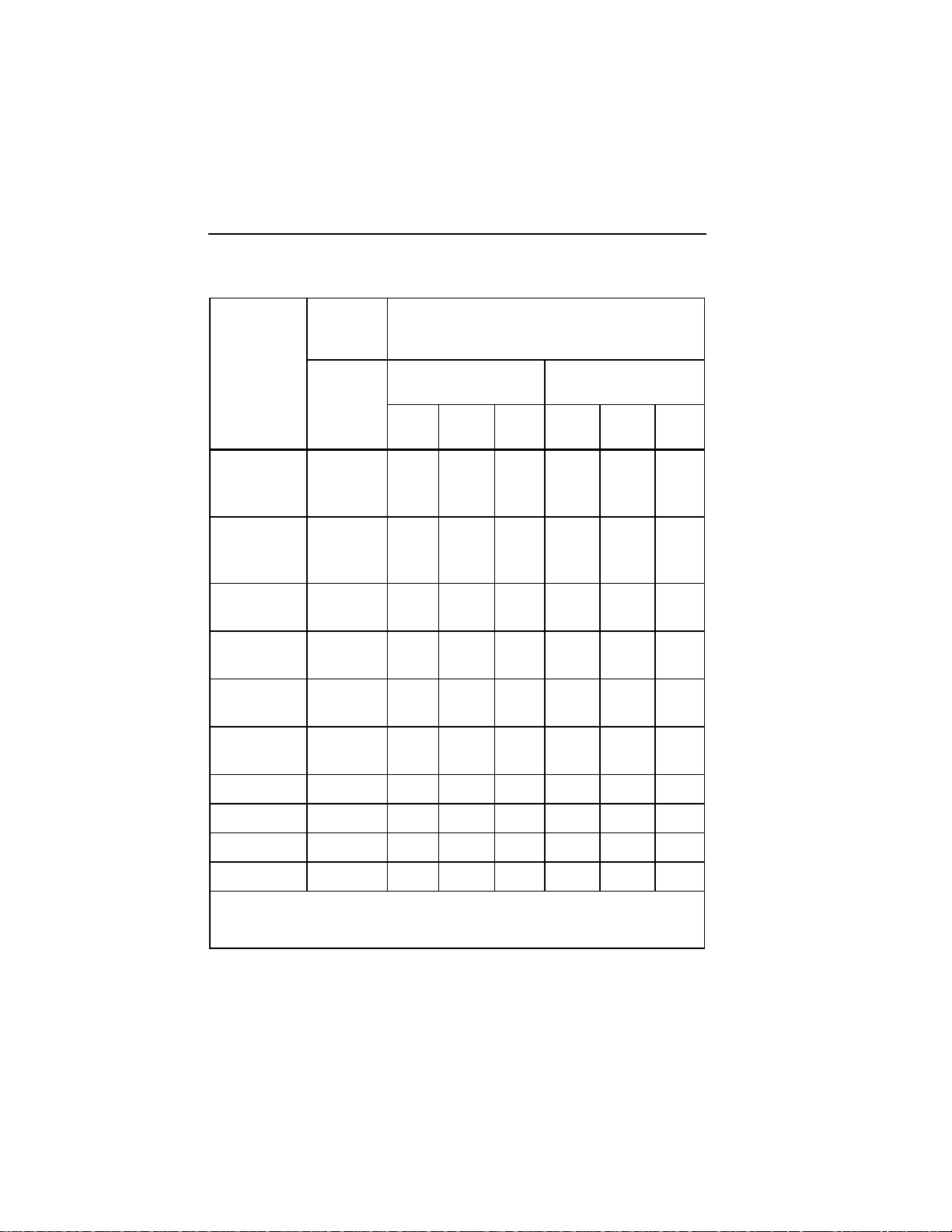
protection), the resistance can be calculated using Table 1. As a basis for this
calculation, the soil resistivity of the location where the earth ground electrode
is to be installed must be known. See “Soil Resistivity.”
1
Page 2
1621
Users Manual Addendum
Table 1. Earth Ground Resistance Calculation
Soil
Resistivity
(ρE)
Earth Ground Resistance e
Soil Type
Moist humus
Earth Ground Rod
Depth in meters
em
3 m
(9 ft)
6 m
(20 ft)
10 m
(33 ft)
30 10 5 3 12 6 3
Earth Ground Strip
[1]
Length in meters
5 m
(16 ft)
10 m
(33 ft)
[1]
20 m
(66 ft)
soil, moor
soil, swamp
Farming soil,
100 33 17 10 40 20 10
loamy and
clay soils
Sandy clay
150 50 25 15 60 30 15
soil
Moist sandy
300 66 33 20 80 40 20
soil
Dry sandy
1000 330 165 100 400 200 100
soil
Concrete
[2]
1 : 5
400 160 80 40
Moist gravel 500 160 80 48 200 100 50
Dry gravel 1000 330 165 100 400 200 100
Stony gravel 30000 1000 500 300 1200 600 300
Rock 107 - - - - - -
[1]
All values in the table are in meters except where specifically noted
[2]
For 1 : 7 concrete mixtures, increase value 24 %
2
Page 3
Earth Ground Tester
Addendum to Users Manual
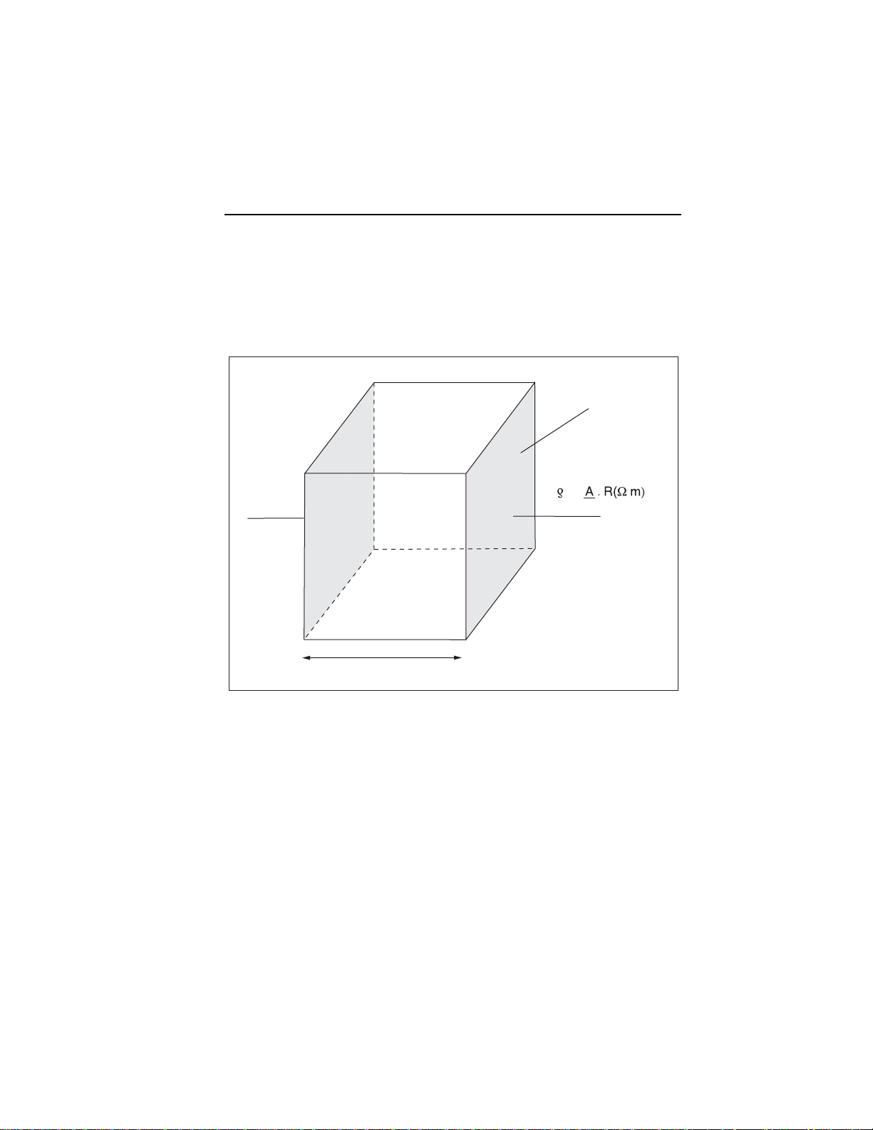
Soil Resistivity
Soil resistivity (ρE) is the resistance measured between two opposing surfaces
of a cube of soil, with a lateral length of 1 meter. Soil resistivity is measured in
ohms-meters (em). See Figure 1.
2
A = 1m
=
E
L
L = 1m
Figure 1. Soil Resistivity
evp007.eps
Soil resistivity primarily depends on soil type (like farming soil, dry sand,
moist sand, concrete, gravel), although seasonal changes can also influence
resistivity. Dry soil has a higher resistivity than moist soil, and frozen ground
has a higher resistivity than dry, warm sand. See Figure 2 for examples of how
resistivity can change over the course of a year.
3
Page 4

1621
Users Manual Addendum
28
24
20
E
16
12
Earth Resistance R
8
4
0
1
0
14
12
10
E
8
6
4
Earth Resistance R
2
0
2 3 4 5 6 7 8 9 10 11 12
Jan
Temporal change of the earthing resistance of a set earth electrode.
10
2 3 4 5 6 7 8 9 10 11 12
Temporal change of the earthing resistance of a buried earth electrode.
DecJuly
DecJulyJan
evp008.eps
Figure 2. Examples of Temporal Changes to Resistivity
Measuring Method
The current-voltage measuring method is demonstrated in Figure 3.
In Figure 3, ac generator G directs current I to earth ground electrode E (earth
ground electrode resistance R
electrode resistance R
H).
E) and auxiliary earth electrode H (auxiliary earth
Voltage U
E drops on earth ground resistance RE (UE proportional to RE). This
voltage is measured by probe S. With a 3-wire circuit, instrument sockets E
and ES are connected to each other, so the voltage drop of the cable between
socket E and the earth ground electrode is not measured. (In a 4-wire circuit, a
separate cable connects socket ES to the earth ground electrode.) Because the
voltage measuring circuit is high impedance, the influence of probe resistance
R
S is negligible. Therefore, the earth ground resistance is calculated as:
R
E = UMEAS / I
and is independent of the resistance of the auxiliary earth electrode R
H.
AC generator G runs at a frequency between 70 and 140 Hz. It must be within
5 Hz of one of the nominal frequencies of 16-2/3, 50 or 60 Hz and their
harmonic waves. A frequency selective filter is inserted and adjusted to the
generator frequency.
4
Page 5

Earth Ground Tester
Addendum to Users Manual
I
U
meas
G
II
E
ES
V
S
H
E
R
E
U
E
Figure 3. Current Voltage Measuring Method
S
R
S
H
R
H
evp009.eps
Potential Gradient Area
When electric current flows through an earth ground electrode, the area around
the electrode develops what is called the “potential gradient area.” When
selecting a location to insert the probe into the ground, you will need to
determine the size of this potential gradient area because you must place the
probe outside this area. Placing the probe inside the area will lead to inaccurate
resistance measurements.
The size of the potential gradient area is determined by soil resistivity. Soils
with high resistivity (bad conductivity) have larger diameters, typically 30 to
60 m (100 to 200 ft); soils with a low resistance (good conductivity) have
comparatively small diameters, typically 10 to 15 m (33 to 50 ft).
As you increase the distance between the probe and earth ground electrode, the
voltage measured between the earth ground electrode and probe decreases.
When the probe is at a distance where the voltage no longer changes, the
voltage has leveled to earth potential ΦE and the probe is outside the potential
gradient area. See Figure 4.
Measuring the probe and auxiliary earth electrode resistances helps to
determine the size of the potential gradient area. Because low resistances result
in smaller potential gradient areas (and vice versa), you must take into account
5
Page 6

1621
Users Manual Addendum
that soil with good conductivity (low resistance) results in a steep voltage
shape, and therefore a higher step voltage. If necessary, check the potential of
such systems.
To use the correct voltage drop from the earth ground resistance (the resistance
between the earth ground electrode and the soil potential ΦE), ensure the probe
is placed outside the potential gradient areas of the earth ground electrode and
the auxiliary earth electrode. Further, it is advisable to repeat each
measurement with repositioned probes, and only regard a measurement as
successful and accurate if several subsequent measurements result in the same
value.
A distance of 20 m (64 ft) between the earth ground electrode and auxiliary
electrode, and a distance of 20 m (64 ft) between the auxiliary electrode and
probe, is normally sufficient.
U
6
U
S
E
Figure 4. Potential Gradient Area
E
U
40 60 m (197 ft)
evp010.eps
Page 7

Earth Ground Tester
Addendum to Users Manual
Demonstration of Potential Gradient Area’s Influence
on Measurements
This section demonstrates how placing a probe inside the potential gradient
area of an earth ground electrode leads to incorrect measurements. As shown
in Figure 5, probes S1, S2 and S4 are positioned inside the potential gradient
area, and probe S3 is positioned outside the potential gradient area.
Probes S1 and S2 deliver voltages (US1 and US2) that are too low, which
means the earth ground resistance is too low. Probe S4 delivers a voltage
(US4) that is too high, which means the earth ground resistance is too high.
Only probe S3 delivers an unaltered voltage (US3) between the earth ground
electrode and soil potential ΦE.
U
G
I
U
S1
VV V
I
1
E
1
S
1
U
S2
I
2
E
2
S
2
G
U
S3
S
3
U
S4
I
V
H
S
4
U
S1
U
S2
U
S3
U
G
U
S4
evp011.eps
Figure 5. Demonstration of Potential Gradient Area's Influence on
Measurements
7
 Loading...