

Page 1

Operation and Administration
Manual
1
Page 2

Contents
1 Introduction. 6
2 Overview 6
3 Terminology 6
4 Warranty Information. 6
4.1 Warranty terms. . . . . . . . . . . . . . . . . . . . . . . . . . . . . . . . . . . . . . . . . . . . . . . . . . 6
4.2 Special notes for use with generators. . . . . . . . . . . . . . . . . . . . . . . . . . . . . . . . . . . . . . 7
I SmartFill Operation and Administration 8
5 Communications Setup 8
5.1 3G . . . . . . . . . . . . . . . . . . . . . . . . . . . . . . . . . . . . . . . . . . . . . . . . . . . . . . . . 8
5.1.1 Details for the 3G SIM . . . . . . . . . . . . . . . . . . . . . . . . . . . . . . . . . . . . . . . . . 8
6 Using the System to Get Fuel 9
7 Short Cut keys 9
8 Adding Vehicle Keys/VINs and/or Driver Keys and PINs 9
8.1 Unit is online to the Website via 3G, WiFi or Direct Ethernet . . . . . . . . . . . . . . . . . . . . . . . . 9
8.2 Unit is oine and data transfer is done via a USB stick . . . . . . . . . . . . . . . . . . . . . . . . . . . 9
8.2.1 Browser Notes . . . . . . . . . . . . . . . . . . . . . . . . . . . . . . . . . . . . . . . . . . . . . 10
9 The SmartFill GEN 2 Admin Menu 10
9.1 Vehicles . . . . . . . . . . . . . . . . . . . . . . . . . . . . . . . . . . . . . . . . . . . . . . . . . . . . . 11
9.2 Plant . . . . . . . . . . . . . . . . . . . . . . . . . . . . . . . . . . . . . . . . . . . . . . . . . . . . . . . 12
9.3 Drivers . . . . . . . . . . . . . . . . . . . . . . . . . . . . . . . . . . . . . . . . . . . . . . . . . . . . . . 12
9.4 View Transactions . . . . . . . . . . . . . . . . . . . . . . . . . . . . . . . . . . . . . . . . . . . . . . . . 13
9.5 Unit . . . . . . . . . . . . . . . . . . . . . . . . . . . . . . . . . . . . . . . . . . . . . . . . . . . . . . . 14
9.6 Time and Date . . . . . . . . . . . . . . . . . . . . . . . . . . . . . . . . . . . . . . . . . . . . . . . . . 14
9.7 Access . . . . . . . . . . . . . . . . . . . . . . . . . . . . . . . . . . . . . . . . . . . . . . . . . . . . . . 15
9.7.1 Admin . . . . . . . . . . . . . . . . . . . . . . . . . . . . . . . . . . . . . . . . . . . . . . . . . . 15
9.7.2 Installer . . . . . . . . . . . . . . . . . . . . . . . . . . . . . . . . . . . . . . . . . . . . . . . . . 15
9.8 Import/Export to Website . . . . . . . . . . . . . . . . . . . . . . . . . . . . . . . . . . . . . . . . . . . 16
10 SmartFill Gen 2 Website Operation and Conguration 17
10.1 Creating Your Website and Adding Your First Unit . . . . . . . . . . . . . . . . . . . . . . . . . . . . . . 17
10.2 Logging In Once the Website is Created . . . . . . . . . . . . . . . . . . . . . . . . . . . . . . . . . . . . 17
10.3 Transactions Page . . . . . . . . . . . . . . . . . . . . . . . . . . . . . . . . . . . . . . . . . . . . . . . . 18
10.3.1 View . . . . . . . . . . . . . . . . . . . . . . . . . . . . . . . . . . . . . . . . . . . . . . . . . . . 18
10.3.2 Columns - . . . . . . . . . . . . . . . . . . . . . . . . . . . . . . . . . . . . . . . . . . . . . . . . 19
10.4 Setting up Vehicle and Plant Details . . . . . . . . . . . . . . . . . . . . . . . . . . . . . . . . . . . . . . 19
10.4.1 Add Vehicle/Plant . . . . . . . . . . . . . . . . . . . . . . . . . . . . . . . . . . . . . . . . . . . 20
10.4.2 View . . . . . . . . . . . . . . . . . . . . . . . . . . . . . . . . . . . . . . . . . . . . . . . . . . 20
10.4.3 Columns . . . . . . . . . . . . . . . . . . . . . . . . . . . . . . . . . . . . . . . . . . . . . . . . 20
10.4.4 Add Vehicle/Plant . . . . . . . . . . . . . . . . . . . . . . . . . . . . . . . . . . . . . . . . . . . . 20
10.4.5 Unit Allocation . . . . . . . . . . . . . . . . . . . . . . . . . . . . . . . . . . . . . . . . . . . . . 20
10.4.6 Transaction Input . . . . . . . . . . . . . . . . . . . . . . . . . . . . . . . . . . . . . . . . . . . . 21
10.4.7 Time of Day Access . . . . . . . . . . . . . . . . . . . . . . . . . . . . . . . . . . . . . . . . . . 21
10.4.8 Fill Limits . . . . . . . . . . . . . . . . . . . . . . . . . . . . . . . . . . . . . . . . . . . . . . . . 21
10.4.9 Daily Allocation . . . . . . . . . . . . . . . . . . . . . . . . . . . . . . . . . . . . . . . . . . . . 21
10.5 Setting up Drivers . . . . . . . . . . . . . . . . . . . . . . . . . . . . . . . . . . . . . . . . . . . . . . . . 21
10.5.1 View . . . . . . . . . . . . . . . . . . . . . . . . . . . . . . . . . . . . . . . . . . . . . . . . . . 21
10.5.2 Add Driver . . . . . . . . . . . . . . . . . . . . . . . . . . . . . . . . . . . . . . . . . . . . . . . . 22
10.5.3 Columns . . . . . . . . . . . . . . . . . . . . . . . . . . . . . . . . . . . . . . . . . . . . . . . . 22
10.5.4 Unit Allocation . . . . . . . . . . . . . . . . . . . . . . . . . . . . . . . . . . . . . . . . . . . . . 22
10.5.5 Time of Day Access . . . . . . . . . . . . . . . . . . . . . . . . . . . . . . . . . . . . . . . . . . 22
10.5.6 Fill Limits . . . . . . . . . . . . . . . . . . . . . . . . . . . . . . . . . . . . . . . . . . . . . . . . 22
10.5.7 Daily Allocation . . . . . . . . . . . . . . . . . . . . . . . . . . . . . . . . . . . . . . . . . . . . 22
10.5.8 Transaction Input . . . . . . . . . . . . . . . . . . . . . . . . . . . . . . . . . . . . . . . . . . . . 22
10.5.9 Supervisor Inputs . . . . . . . . . . . . . . . . . . . . . . . . . . . . . . . . . . . . . . . . . . . . 23
10.6 Tanks . . . . . . . . . . . . . . . . . . . . . . . . . . . . . . . . . . . . . . . . . . . . . . . . . . . . . . 23
2
Page 3
10.6.1 View . . . . . . . . . . . . . . . . . . . . . . . . . . . . . . . . . . . . . . . . . . . . . . . . . . 23
10.6.2 Add Tanks . . . . . . . . . . . . . . . . . . . . . . . . . . . . . . . . . . . . . . . . . . . . . . . 23
10.6.3 Tanks - Conguration . . . . . . . . . . . . . . . . . . . . . . . . . . . . . . . . . . . . . . . . . 24
10.6.4 All . . . . . . . . . . . . . . . . . . . . . . . . . . . . . . . . . . . . . . . . . . . . . . . . . . . . 24
10.6.5 Dips . . . . . . . . . . . . . . . . . . . . . . . . . . . . . . . . . . . . . . . . . . . . . . . . . . . 24
10.6.6 Deliveries . . . . . . . . . . . . . . . . . . . . . . . . . . . . . . . . . . . . . . . . . . . . . . . . 24
10.6.7 History - Conguration . . . . . . . . . . . . . . . . . . . . . . . . . . . . . . . . . . . . . . . . . 24
10.7 User Dened Data . . . . . . . . . . . . . . . . . . . . . . . . . . . . . . . . . . . . . . . . . . . . . . . 24
10.7.1 Denitions . . . . . . . . . . . . . . . . . . . . . . . . . . . . . . . . . . . . . . . . . . . . . . . . 25
10.7.2 Unit Allocation . . . . . . . . . . . . . . . . . . . . . . . . . . . . . . . . . . . . . . . . . . . . . 25
10.8 Jobs . . . . . . . . . . . . . . . . . . . . . . . . . . . . . . . . . . . . . . . . . . . . . . . . . . . . . . . 25
10.8.1 Add Job . . . . . . . . . . . . . . . . . . . . . . . . . . . . . . . . . . . . . . . . . . . . . . . . . 25
10.8.2 Denitions . . . . . . . . . . . . . . . . . . . . . . . . . . . . . . . . . . . . . . . . . . . . . . . 25
10.8.3 Unit Allocation . . . . . . . . . . . . . . . . . . . . . . . . . . . . . . . . . . . . . . . . . . . . . 25
10.9 SmartFill Units . . . . . . . . . . . . . . . . . . . . . . . . . . . . . . . . . . . . . . . . . . . . . . . . . 26
10.9.1 Status . . . . . . . . . . . . . . . . . . . . . . . . . . . . . . . . . . . . . . . . . . . . . . . . . . 26
10.9.2 Info . . . . . . . . . . . . . . . . . . . . . . . . . . . . . . . . . . . . . . . . . . . . . . . . . . . 26
10.9.3 SmartFill GEN 2 Import . . . . . . . . . . . . . . . . . . . . . . . . . . . . . . . . . . . . . . . . 26
10.9.4 SmartFill Gen 2 Export . . . . . . . . . . . . . . . . . . . . . . . . . . . . . . . . . . . . . . . . . 26
10.9.5 Add New Unit . . . . . . . . . . . . . . . . . . . . . . . . . . . . . . . . . . . . . . . . . . . . . . 26
10.9.6 Congure - General . . . . . . . . . . . . . . . . . . . . . . . . . . . . . . . . . . . . . . . . . . . 26
10.9.7 Congure - Pumps . . . . . . . . . . . . . . . . . . . . . . . . . . . . . . . . . . . . . . . . . . . 27
10.9.8 Tank Gauges . . . . . . . . . . . . . . . . . . . . . . . . . . . . . . . . . . . . . . . . . . . . . . 28
11 Troubleshooting at the SmartFill GEN 2 unit. 28
11.1 Key Problems ?. . . . . . . . . . . . . . . . . . . . . . . . . . . . . . . . . . . . . . . . . . . . . . . . . . 28
11.1.1 Require more vehicle keys ? . . . . . . . . . . . . . . . . . . . . . . . . . . . . . . . . . . . . . . . 28
11.1.2 SmartFill GEN 2 does nothing when a key is presented. . . . . . . . . . . . . . . . . . . . . . . . . 29
11.1.3 Keys shows as `INVALID'. . . . . . . . . . . . . . . . . . . . . . . . . . . . . . . . . . . . . . . . 29
11.1.4 Lost vehicle keys. . . . . . . . . . . . . . . . . . . . . . . . . . . . . . . . . . . . . . . . . . . . . 29
11.1.5 Lost door lock key. . . . . . . . . . . . . . . . . . . . . . . . . . . . . . . . . . . . . . . . . . . . 29
11.2 PIN Number Problems ?. . . . . . . . . . . . . . . . . . . . . . . . . . . . . . . . . . . . . . . . . . . . . 29
11.2.1 Not asking for PIN number. . . . . . . . . . . . . . . . . . . . . . . . . . . . . . . . . . . . . . . 29
11.3 Pump / dispenser problems. . . . . . . . . . . . . . . . . . . . . . . . . . . . . . . . . . . . . . . . . . . 29
11.3.1 Pump stops after a short period. . . . . . . . . . . . . . . . . . . . . . . . . . . . . . . . . . . . . 29
11.3.2 SmartFill GEN 2 is not recording Litres accurately. . . . . . . . . . . . . . . . . . . . . . . . . . . 29
II SmartDip Operation 31
12 Overview 31
13 Operation 31
List of Figures
1 Admin Menu . . . . . . . . . . . . . . . . . . . . . . . . . . . . . . . . . . . . . . . . . . . . . . . . . . . 10
2 Vehicles Menu . . . . . . . . . . . . . . . . . . . . . . . . . . . . . . . . . . . . . . . . . . . . . . . . . . 11
3 Plant Menu . . . . . . . . . . . . . . . . . . . . . . . . . . . . . . . . . . . . . . . . . . . . . . . . . . . 12
4 Drivers Menu . . . . . . . . . . . . . . . . . . . . . . . . . . . . . . . . . . . . . . . . . . . . . . . . . . 12
5 View Transactions Menu . . . . . . . . . . . . . . . . . . . . . . . . . . . . . . . . . . . . . . . . . . . . 13
6 Unit Menu . . . . . . . . . . . . . . . . . . . . . . . . . . . . . . . . . . . . . . . . . . . . . . . . . . . . 14
7 Time and Date Menu . . . . . . . . . . . . . . . . . . . . . . . . . . . . . . . . . . . . . . . . . . . . . . 14
8 Unit Access Settings . . . . . . . . . . . . . . . . . . . . . . . . . . . . . . . . . . . . . . . . . . . . . . 15
9 Installer Access Settings . . . . . . . . . . . . . . . . . . . . . . . . . . . . . . . . . . . . . . . . . . . . . 15
10 Import/Export Menu . . . . . . . . . . . . . . . . . . . . . . . . . . . . . . . . . . . . . . . . . . . . . . 16
11 Initial Account Activation Page . . . . . . . . . . . . . . . . . . . . . . . . . . . . . . . . . . . . . . . . 17
12 Website Transaction Page . . . . . . . . . . . . . . . . . . . . . . . . . . . . . . . . . . . . . . . . . . . 18
13 Conguring the Transactions Page . . . . . . . . . . . . . . . . . . . . . . . . . . . . . . . . . . . . . . . 19
14 Vehicles Page . . . . . . . . . . . . . . . . . . . . . . . . . . . . . . . . . . . . . . . . . . . . . . . . . . 19
15 Add Vehicle Page . . . . . . . . . . . . . . . . . . . . . . . . . . . . . . . . . . . . . . . . . . . . . . . . 20
16 Drivers Page . . . . . . . . . . . . . . . . . . . . . . . . . . . . . . . . . . . . . . . . . . . . . . . . . . . 21
17 Add Driver Page . . . . . . . . . . . . . . . . . . . . . . . . . . . . . . . . . . . . . . . . . . . . . . . . . 22
18 Tanks Page . . . . . . . . . . . . . . . . . . . . . . . . . . . . . . . . . . . . . . . . . . . . . . . . . . . 23
19 Tank Add Page . . . . . . . . . . . . . . . . . . . . . . . . . . . . . . . . . . . . . . . . . . . . . . . . . 24
3
Page 4
20 User Dened Data Page . . . . . . . . . . . . . . . . . . . . . . . . . . . . . . . . . . . . . . . . . . . . 25
21 Jobs Page . . . . . . . . . . . . . . . . . . . . . . . . . . . . . . . . . . . . . . . . . . . . . . . . . . . . 25
22 SmartFill Units Page . . . . . . . . . . . . . . . . . . . . . . . . . . . . . . . . . . . . . . . . . . . . . . 26
23 Conguration - General . . . . . . . . . . . . . . . . . . . . . . . . . . . . . . . . . . . . . . . . . . . . . 27
24 Conguration - Pumps . . . . . . . . . . . . . . . . . . . . . . . . . . . . . . . . . . . . . . . . . . . . . 27
25 Conguration - Tank Guages . . . . . . . . . . . . . . . . . . . . . . . . . . . . . . . . . . . . . . . . . . 28
4
Page 5
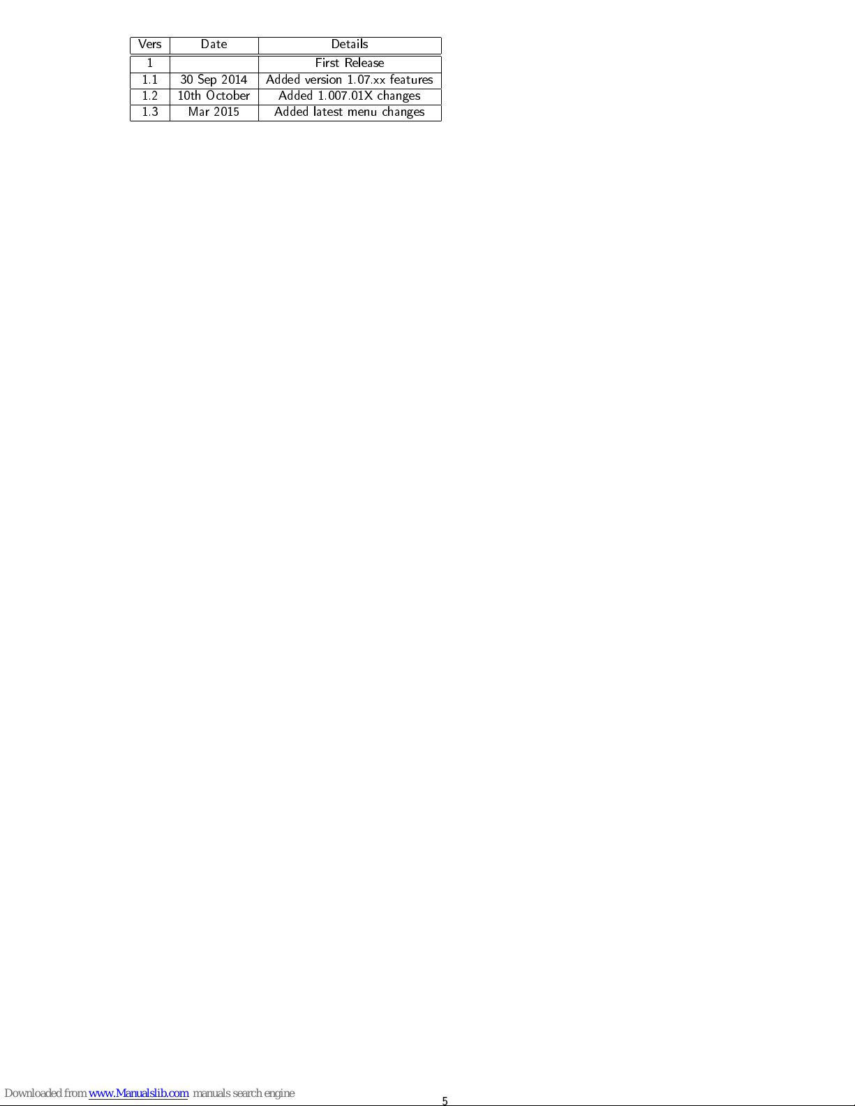
Vers Date Details
1 First Release
1.1 30 Sep 2014 Added version 1.07.xx features
1.2 10th October Added 1.007.01X changes
1.3 Mar 2015 Added latest menu changes
5
Page 6
1 Introduction
.
This manual is designed to step through the operation and admin setup of a SmartFill GEN 2 system. Please contact the
manufacturer should you have any suggestions, or error corrections.
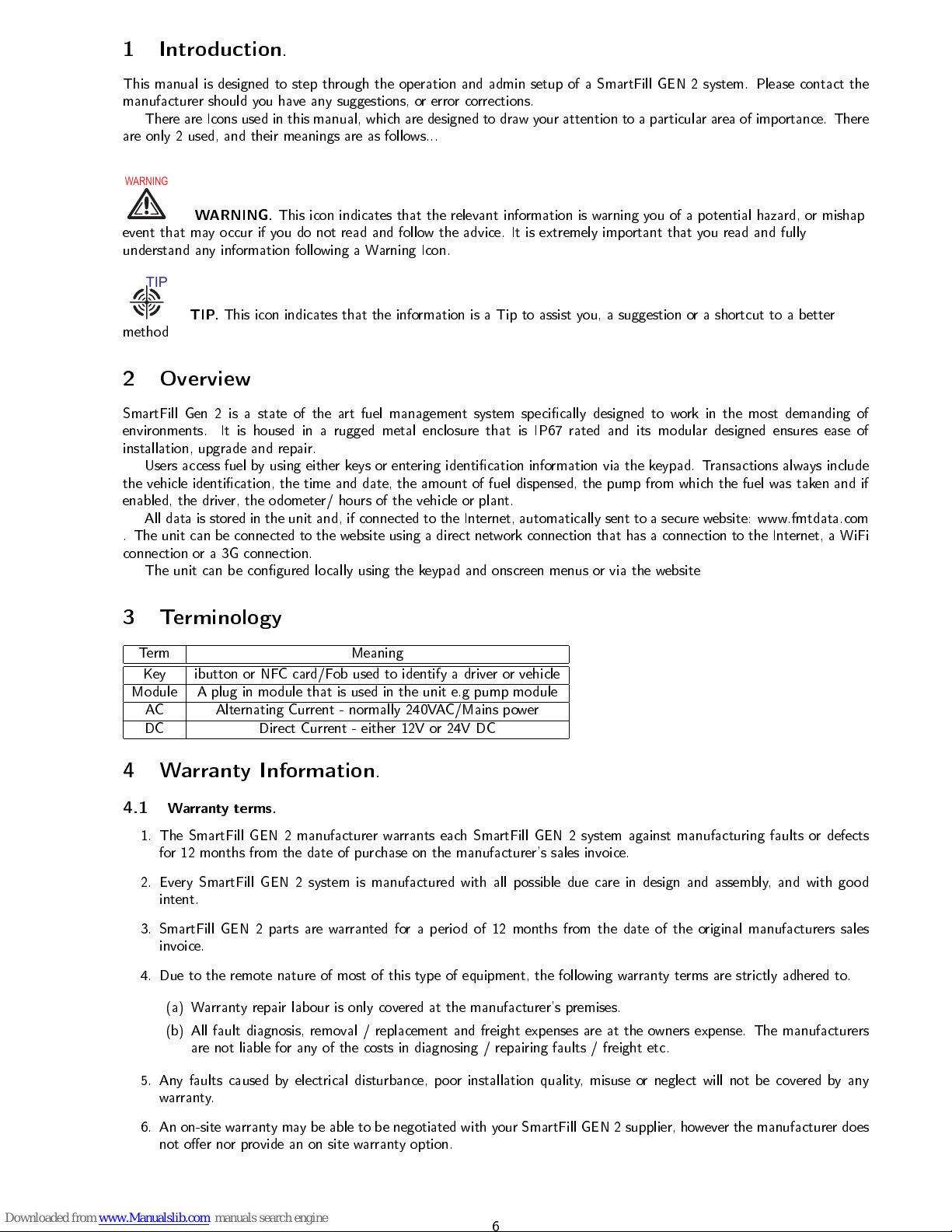
There are Icons used in this manual, which are designed to draw your attention to a particular area of importance. There
are only 2 used, and their meanings are as follows...
WARNING
WARNING.
This icon indicates that the relevant information is warning you of a potential hazard, or mishap
event that may occur if you do not read and follow the advice. It is extremely important that you read and fully
understand any information following a Warning Icon.
TIP
TIP.
This icon indicates that the information is a Tip to assist you, a suggestion or a shortcut to a better
method
2 Overview
SmartFill Gen 2 is a state of the art fuel management system specically designed to work in the most demanding of
environments. It is housed in a rugged metal enclosure that is IP67 rated and its modular designed ensures ease of
installation, upgrade and repair.
Users access fuel by using either keys or entering identication information via the keypad. Transactions always include
the vehicle identication, the time and date, the amount of fuel dispensed, the pump from which the fuel was taken and if
enabled, the driver, the odometer/ hours of the vehicle or plant.
All data is stored in the unit and, if connected to the Internet, automatically sent to a secure website: www.fmtdata.com
. The unit can be connected to the website using a direct network connection that has a connection to the Internet, a WiFi
connection or a 3G connection.
The unit can be congured locally using the keypad and onscreen menus or via the website
3 Terminology
Term Meaning
Key ibutton or NFC card/Fob used to identify a driver or vehicle
Module A plug in module that is used in the unit e.g pump module
AC Alternating Current - normally 240VAC/Mains power
DC Direct Current - either 12V or 24V DC
4 Warranty Information
.
4.1
Warranty terms.
1. The SmartFill GEN 2 manufacturer warrants each SmartFill GEN 2 system against manufacturing faults or defects
for 12 months from the date of purchase on the manufacturer's sales invoice.
2. Every SmartFill GEN 2 system is manufactured with all possible due care in design and assembly, and with good
intent.
3. SmartFill GEN 2 parts are warranted for a period of 12 months from the date of the original manufacturers sales
invoice.
4. Due to the remote nature of most of this type of equipment, the following warranty terms are strictly adhered to.
(a) Warranty repair labour is only covered at the manufacturer's premises.
(b) All fault diagnosis, removal / replacement and freight expenses are at the owners expense. The manufacturers
are not liable for any of the costs in diagnosing / repairing faults / freight etc.
5. Any faults caused by electrical disturbance, poor installation quality, misuse or neglect will not be covered by any
warranty.
6. An on-site warranty may be able to be negotiated with your SmartFill GEN 2 supplier, however the manufacturer does
not oer nor provide an on site warranty option.
6
Page 7
7. The manufacturers may not be held liable for any product or data loss, equipment damage or loss, equipment or
business downtime, personal injury or death which is either directly or indirectly caused by the system hardware or
software, regardless of the cause of the failure.
8. If the above warranty conditions can not be agreed upon or are deemed unacceptable by the client, then the client
must contact their supplier immediately to arrange a resolution, and must not use the SmartFill GEN 2 system until
a resolution is agreed.
4.2
Special notes for use with generators.
WARNING
1. To enable the manufacturers to fully warrant any system connected to a portable generator, the system MUST be
designed so that it is impossible for the generator to be started or stopped while the SmartFill GEN 2 is electrically
connected to the generator power output. The SmartFill GEN 2 must only be powered up after the generator is
running with a stable regulated power supply, and must be disconnected from the power supply before the generator
is turned o.
2. At the very minimum a power failure relay and current sensing relay will be required when generator power is used.
7
Page 8

Part I
SmartFill Operation and Administration
5 Communications Setup
The SmartFill GEN 2 is designed to automatically send data to a central website using either a direct Ethernet connection,
3G or WiFi. Ethernet is standard with all units and 3G or WiFi are optional modules that can be ordered with the unit or
tted later.
5.1 3G
The 3G module is located in the upper left hand corner of the unit to operate it needs to be tted with a 3G data SIM.
The picture below shows how the SIM is tted into the module:
5.1.1 Details for the 3G SIM
The SmartFill GEN 2 module uses a 3G SIM enabled for data to send data to your website account. Below are the details
of what is required for the card:
•
Application Description:
A machine to machine application where data is automatically send to a website
•
Data Capacity
: Minimum of 500MB per month (.5GB)
•
Passcode Settings:
Passcode should be disabled. This should be done when the card is supplied, but can also be
done by tting the card into a phone and using the phone settings menu to turn on this functionality
•
Physical Size:
To t into the module the SIM must a Standard SIM, as shown below NOT a micro or nano SIM.
Mini SIM
•
Service Provider/ Plan:
All service providers can provide a data SIM and plans vary between suppliers. The default
conguration for the access point in the SmartFill unit is Telstra, but this can be changed if needs be in the SmartFill
set up menu.
Telstra have a machine to machine data plan, M2M, which is specically designed for this type of application. Details can be
found at:
http://www.telstra.com.au/business-enterprise/business-products/managed-services/machine-2-machine/
Once the SIM is installed, you can view the status of the connection by holding down the 4 key.
8
Page 9
6 Using the System to Get Fuel
1. The driver touches the an ID key (button) onto the sensor or swipes a card on the SmartFill GEN 2 unit or enters
either a VIN (Vehicle Indentication Number) or PIN (Personal Indenticaiton Number)
2. The SmartFill GEN 2 checks if the key is authorized. If the key is not authorized, the pump won't start, and the
display will show Key Not Valid.
3. This system identies whether a driver or vehicle key has been used. If a vehicle key has been used it, it may request
the driver to enter a PIN, and/or an odometer reading depending on how the system has been congured.
4. If the following options are turned on
(a) The SmartFill GEN 2 requests the Speedo / hour meter reading. The driver enters this into the SmartFill GEN
2 keypad.
(b) The SmartFill GEN 2 requests the PIN number. The driver enters this into the keypad
(c) The SmartFill GEN 2 checks the pin number. If the pin number is not valid, the fuel pump won't start.
5. The driver fuels the vehicle. Once the fuel delivery is complete, the SmartFill GEN 2 stores the details. If the system
is online, the transaction information is automatically sent to the appropriate account on the SmartFill website
7 Short Cut keys
The SmartFill GEN 2 has a series of short cut keys that allows easy access to commonly requested information. These are
accessed by holding down the relevant key:
1.
CLR
- Displays the current tank levels if a SmartDip module is tted and congured
2.0- Enables the entry of details regarding a fuel delivery
3.4- Displays the status of the network connection, which can be either 3G, WiFi or Ethernet
4.5-Displays the details of the most recent transactions
5.
6 -
Displays the unit's model and serial number
8 Adding Vehicle Keys/VINs and/or Driver Keys and PINs
Keys and PINs for drivers, vehicles and plant can either be added at the unit using the Admin menu options: add vehicle1,
add plant or add driver2 or at the website.Use the add vehicle button 10.4.1or add driver button to add new vehicles, plant
or drivers to add these items at the website on the corresponding pages . To edit an existing entry click of the eld and
edit the text using backspace and delete as required
•
Driver names must be added to the website and will be automatically downloaded to the unit
•
Vehicle details such as registration, make and model should be added at the website. Not all of the vehicles details
are downloaded to the unit
8.1 Unit is online to the Website via 3G, WiFi or Direct Ethernet
Any information added at the unit or on the website will be automatically synchronised between the two.
WARNING
Keys or
PINs/VINs deleted at the website must be added back at the website if they are to be reinstated. Adding them at the unit
will result in them being removed when the unit synchronises with the website.
8.2 Unit is oine and data transfer is done via a USB stick
NB: The SmartFill unit must have 1.07.xxx software of later to use this procedure
It is recommended that a single USB drive be used for all SmartFill units and les.
At the SmartFill Unit:
1. Insert the USB drive.
2. Enter the administration menu (hold CLR and ENT keys together for a few seconds, enter 1234 at the prompt, then
press ENT).
3. Select (5) Unit.
9
Page 10
4. Select (2) Import Data. (If you get an error, remove and re-insert the USB drive and try again. If is still doesn't work,
then skip this step as the le was possibly not saved to the USB drive.)
5. Select (3) Export Data.
6. When the download has completed successfully, remove the USB drive.
7. Repeat steps (1) - (6) for the other SmartFill units.
At the Website:
1. Insert the USB drive into the computer.
2. Log in to your account and select the 'SmartFill Units' menu.
3. Select 'Import' from the left submenu.
4. Select the le from the rst unit to import. e.g. '2183web.dat' and press the Import button.
5. When prompted to download the le, press the 'Download File' button.
6. Select the top directory of the USB drive and save the le as 'xxxxunit.dat' (see Browser Notes below), where xxxx
is the serial number. e.g. '2183unit.dat' 7) Repeat from (3) for the remaining units.
7. Eject and remove the USB drive.
The data that has been exported can be imported into the SmartFill unit next time you need to export data from the unit.
It doesn't have to be done straight away. You can now select the 'Transactions' menu to view the transactions.
8.2.1 Browser Notes
Depending on the browser used, saving the le will be dierent. It is important to do this correctly to prevent any problems.
Here are some notes for the latest versions of the most common browsers.
1.
Internet Explorer (IE)
You will be prompted at the bottom of the screen to open or save the le. Press the small
triangle to the right of the Save button and select 'Save as'. Select the top level directory of the USB drive and press
Save. If prompted to replace it, press 'Yes'. You can then cancel any remaining message at the bottom of the browser
screen.
2.
FireFox
When prompted where to save the le, select the top level directly of the USB drive and press Save. If
prompted to replace it, press 'Yes'. If you are not prompted where to save the le, this must be changed in the
FireFox settings, as follows. Press the FireFox settings icon (three stacked horizontal lines to the far right of the
address bar). Make sure the General tab is selected (rst on the left). Under 'Downloads', select 'Always ask me
where to save les'.
3.
Chrome
When prompted where to save the le, select the top level directly of the USB drive and press Save. If
prompted to replace it, press 'Yes'. If you are not prompted where to save the le, this must be changed in the Chrome
settings, as follows. Press the Chrome settings icon (three stacked horizontal lines to the far right of the address bar)
and select 'Settings'. If you see at the bottom of the page a blue link saying 'Show advanced settings. . .', press it.
Scroll down to the 'Downloads' heading and select 'Ask where to save each le before downloading'.
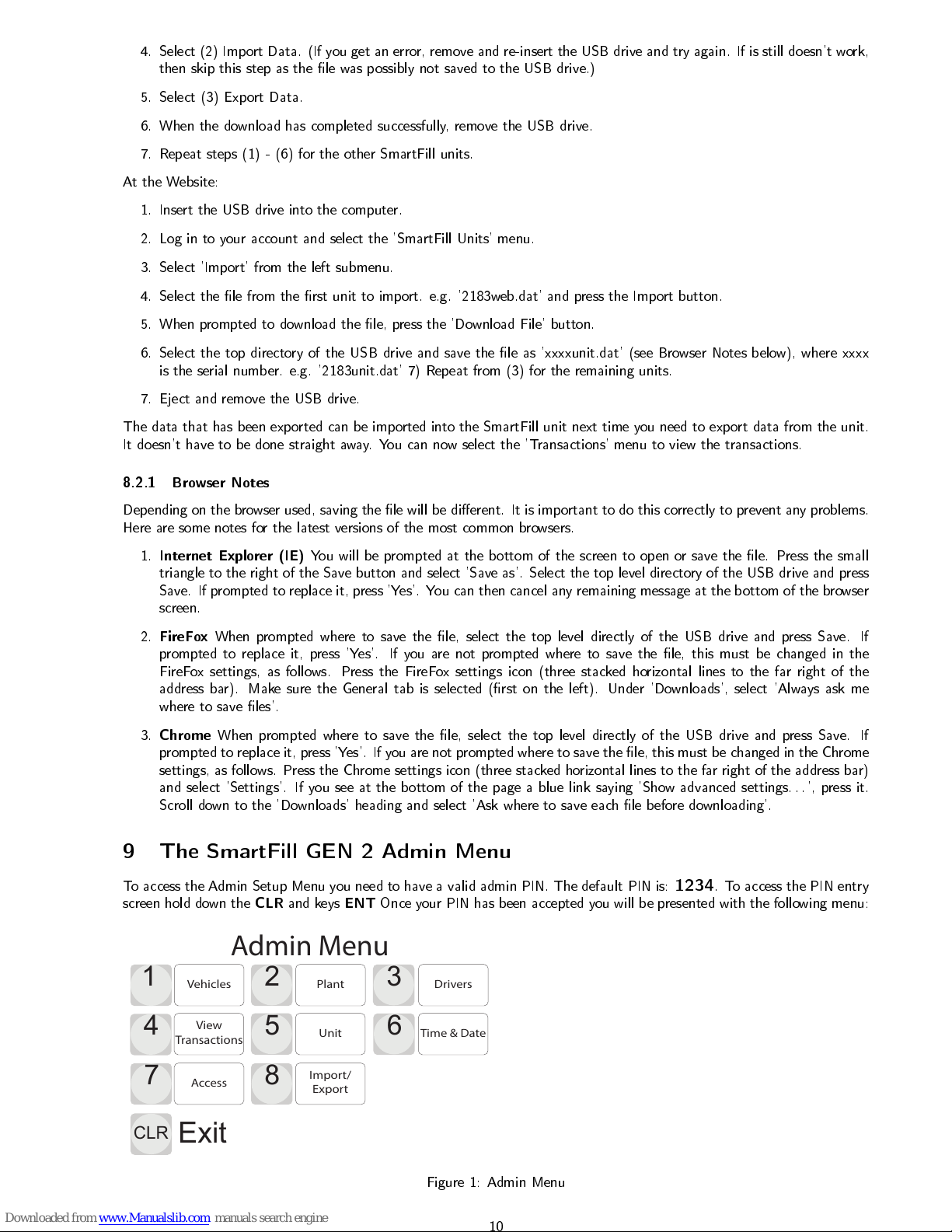
9 The SmartFill GEN 2 Admin Menu
To access the Admin Setup Menu you need to have a valid admin PIN. The default PIN is:
1234
. To access the PIN entry
screen hold down the
CLR
and keys
ENT
Once your PIN has been accepted you will be presented with the following menu:
1
2
3
5
7
8
CLR
Exit
Vehicles Plant
Drivers
Admin Menu
View
Transactions
Unit
Access
Import/
Export
6
Time & Date
4
Figure 1: Admin Menu
10
Page 11

To select a menu item push the corresponding key on the keypad. You will then be presented with the choices available
for that menu selection. The menu below appears if you push key number '1'.
9.1 Vehicles
1
2
3
4
5
6
CLR
Back
Vehicles
On / O
Add Delete
Vehicles
View /
Delete
Speedo
On / O
Hourmeter
On/O
Figure 2: Vehicles Menu
This menu is used to set what the inputs the user will be asked to enter to identify a vehicle and allows codes or keys to be
added, deleted etc. There are seven items in this menu :
1.
Vehicle On/O
(a)
Key
or (
Default
)
(b)
VIN
(c)
None
In this menu you set whether a vehicle ID is required and if it is, how it will be entered: either using a key (card or ibutton)
or a vehicle identication number (VIN)
1.
Add
- allows the addition of vehicle Keys or VINs to the system. If Key has been selected the actual key must be
presented to the system to enter it. The key number cannot be directly entered. VINs are added by using the keypad
to enter the value.
2.
Delete
- allows Keys or VINs to be deleted from the system. Keys can be deleted by presenting the key to be deleted.
VINs can be deleted by entering the VIN from the keypad
3.
View/Delete
- Keys or VINS in the system can be viewed. Any key or VIN can be deleted by this screen by rst
selecting it and then selecting delete. Deleting a key removes it from the unit and on the website removes it from
being associated with this units, but not other units that are connected to the website.
4.
Speedo On/O
(a) Yes - Driver is required to enter speedo
(b) No - No speedo entry is required
(Default
)
5.
Hourmeter On/O
(a) Yes - Driver is required to enter Hourmeter
(b) No - No speedo entry is required
(Default
)
11
Page 12

9.2 Plant
1
2
3
4
5
6
CLR
Back
Plant
On / O
Add Delete
Plant
View /
Delete
Speedo
On / O
Hourmeter
On/O
Figure 3: Plant Menu
This menu is used to set what the inputs the user will be asked to enter to identify a pice of plant e.g Gen Set or tank and
allows codes or keys to be added, deleted etc. There are seven items in this menu :
1.
Plant On/O
In this menu you set whether a plant ID is required and if it is, how it will be entered: either using a key (card or ibutton)
or a plant identication number (PIN)
1.
Key
or
(a)
PIN
(b)
None(Default
)
2.
Add
- allows the addition of plant Keys or PINs to the system. If Key has been selected the actual key must be
presented to the system to enter it. The key number cannot be directly entered. VINs are added by using the keypad
to enter the value.
3.
Delete
- allows Keys or PINs to be deleted from the system. Keys can be deleted by presenting the key to be deleted.
VINs can be deleted by entering the PIN from the keypad
4.
View/Delete
- Keys or VINS in the system can be viewed. Any key or VIN can be deleted by this screen by rst
selecting it and then selecting delete. Deleting a key removes it from the unit and on the website removes it from
being associated with this units, but not other units that are connected to the website.
5.
Speedo On/O
(a) Yes - Driver is required to enter speedo
(b) No - No speedo entry is required
(Default
)
6.
Hourmeter On/O
(a) Yes - Driver is required to enter Hourmeter
(b) No - No speedo entry is required
(Default
)
9.3 Drivers
1
2
3
4
CLR
Back
Drivers
On / O
Add Delete
Drivers
View /
Delete
Figure 4: Drivers Menu
12
Page 13

This menu is used to set what the inputs the user will be asked to enter to identify a vehicle and allows codes or keys to be
added, deleted etc. There are seven items in this menu :
1.
Drivers On/O
(a) Key - the driver will need to use an I button or card for identication
(b) PIN - The driver will need to enter a PIN for identication)
(c) None - No driver identication is required to operate the system (
Default
)
2.
Add
- allows the addition of Driver Keys or VPNs to the system. If Key has been selected in the Transaction Inputs
Menu, the actual key must be presented to the system to enter it. The key number cannot be directly entered. PINs
are added by using the keypad to enter the value.
3.
Delete
- allows Keys or PINs to be deleted from the system. Keys can be deleted by presenting the key to be deleted.
PINs can be deleted by entering the PIN from the keypadTr
4.
View/Delete-
Keys or VINS in the system can be viewed. Any key or VIN can be deleted by this screen by rst
selecting it and then selecting delete. Deleting a key removes it from the unit and on the website removes it from
being associated with this units, but not other units that are connected to the website.
5.
Import -
used to import Keys or PINs into the system from a USB drive (when the system is online to the website
Keys or PINs are automatically downloaded to the system)
6.
Export
- used to export Keys or PINs from the system to the USB drive (when the system is online to the website
Keys or PINs are automatically uploaded to the website)
9.4 View Transactions
1
2
CLR
Back
View Delete
View Transactions
Figure 5: View Transactions Menu
This menu is used to view transactions that are stored in the unit, export transactions to an Excel format and delete
transactions. There are three options:
1.
View Transactions
- shows all the transactions stored in the unit
2.
Delete
- allows you to delete all transactions in the unit
13
Page 14

9.5 Unit
1
2
3
CLR
Back
Unit Name Import Data
Export Data
Unit Conguration
4
Upgrade
Software
6
Export
Settings
5
Import
Settings
7
Restore
Software
8
Clear
Settings
8
Restart
Figure 6: Unit Menu
1.
Unit Name
- allows you to set or edit the unit name. Use the Help function to understand how to navigate the
keyboard entry. This name is used on the website to identify which unit the transaction came from and to allow the
allocation of keys and PINs to vehicles, drivers and plant
2.
Import Data
- imports a the le that is created from the website export function. This imports all keys, codes and
conguration that exist on the website, but are not in the unit.
3.
Export Data
- exports a le with all the keys, codes and transactions from the unit. This can then be imported into
the website
4.
Upgrade Software -
is used to upgrade the unit's software via the USB port
5.
Import Settings
- is used to import a conguration le
6.
Export Settings -
is used to export a conguration le
7.
Restore Software
- is used to restore the previous version of the software that was installed prior to the last upgrade
8.
Restart
- Reboots the unit, which produces the same result as power cycling it.
9.
Clear Setting
s - Has two options:
(a) Clear Data - clears all keys, codes and transactions
(b) Factory Default - clears all keys, codes, transactions and returns the conguration to the original factory settings
9.6 Time and Date
1
2
3
CLR
Back
Set Time
Set Date
Display
On / O
Set Time & Date
Figure 7: Time and Date Menu
This menu is used to set the system time and date and set whether the time and date will appear on the display. There are
four menu options:
1.
Time
- allows you to set the system time
2.
Date
- allows you to set the system date
14
Page 15

3.
Display On/O
- has two options
(a) No - do not display the time and date
(b) Yes - display the time and date
9.7 Access
1
2
CLR
Back
Admin
Installer
Unit Access Setting
Figure 8: Unit Access Settings
This menu is used to change the Admin password, change the installer password and enable and disable installer access
9.7.1 Admin
Used to change the admin password from the default of 1234 to some other code.
9.7.2 Installer
1
2
CLR
Back
Enable/
Disable
Password
InstallerAccess Settings
Figure 9: Installer Access Settings
1. Enable/Disable - enables or disable installer access. If disabled, no one is able to access the units set up conguration
2. Password - allows the default password to be changed from 1234 to some other password
15
Page 16

9.8 Import/Export to Website
1
2
CLR
Back
Import
Export
Import/Export to Website
Figure 10: Import/Export Menu
This menu is used to export and import all data (transactions, vehicle/plant and driver details) to and from a USB drive
for use with the website.There are two options:
1.
Import -
imports a le exported from the website into the unit. This includes all vehicle, plant, driver details, job
numbers and user dened eld data. The export le is created using the export link on the SmartFill Units page on
the website
2.
Export
- Creates an export le that can be imported into the website. The resultant le is imported using the import
on the SmartFill Units page of the website
16
Page 17

10 SmartFill Gen 2 Website Operation and Conguration
The SmartFill Gen 2 website is used to store all transactional data from the units, conguration information for the unit
and data that is associated with transactions, such as a drivers name or the department to which the vehicle belongs:
The website is located at www.fmtdata.com
10.1 Creating Your Website and Adding Your First Unit
To set up your website and add an unit for the very rst time use your web browser to navigate to www.fmtdata.com/new
Once you arrive at this page enter the serial number and code provided with the unit. A copy if this information is contained
on the USB drive supplied with the unit and a hardcopy is supplied with the unit.
Figure 11: Initial Account Activation Page
Once you do this you will be asked to ll in some company details and create an Admin user name and password. Unless
you change them, these are credentials you will use from now on to log on to the your website. Once you have completed
this step you will be taken to the rst page of your website.
10.2 Logging In Once the Website is Created
Once you have created your website you can log in using the credentials you created in 10.1 at www.fmtdata.com
17
Page 18

10.3 Transactions Page
The transactions page is the rst one that appears when you log on. It displays transactions in the selected date range that
have been transferred to the website from all associated units. You can select the required date range from the drop menu
at the top of the screen
Figure 12: Website Transaction Page
10.3.1 View
Displays the main transaction screen from here you have the following options
18
Page 19

1.
Date Range
- From drop down menu you select what date range you want to display and export. Whatever range is
selected here is what is exported to the CSV le
2.
Export to CSV
- Exports all transactions to a .csv le that can be viewed in Excel
10.3.2 Columns -
If you select Columns on the transactions page you will be presented with the transaction page conguration page. This
page enables you to change the order of the columns by dragging them up or down the table. The item at the top of the
table is show rst. You can change the column headings by selecting the heading name and then over typing it with the
new name. Headings that are grayed out are set in one of the other conguration screen. You can choose which columns
are displayed by dragging and dropping those required into the left hand site table or remove them by dragging them into
the right hand side table.
Figure 13: Conguring the Transactions Page
10.4 Setting up Vehicle and Plant Details
Details for vehicles and plant, such as which key or code (PIN or VIN) is used to identify the equipment and description are
set up on the vehicles and plant page respectively.
Figure 14: Vehicles Page
19
Page 20

10.4.1 Add Vehicle/Plant
The add vehicle button allows you to add a new vehicle. Refer the the gure below. You will be prompted to enter data for
each of the columns that are displayed on the vehicles page. On the input type you must select whether the entry is a key
or a code (PIN/VIN). Once a vehicle is added you can edit it from the vehicles page by selecting and over typing the entry.
Figure 15: Add Vehicle Page
10.4.2 View
The main page provides a overview of existing vehicles and the details that have been associated with tehm. Details of
the key or code are automatically transferred to all selected units. In addition for vehicles the description and registration
details are automatically transferred to all selected, connected units.
Details for existing vehicles can be changed by selecting a cell, such as description and over typing the existing text.
Vehicles can be disabled by deleting them in the unit or selecting the action button next to key or code on the website
10.4.3 Columns
If you select Columns on the vehicles or plant pages you will be presented with the columns conguration page. This page
enables you to change the order of the columns by dragging them up or down the table. The item at the top of the table is
show rst. You can change the column headings by selecting the heading name and then over typing it with the new name.
Headings that are grayed out are set in one of the other conguration screen. You can choose which columns are displayed
by dragging and dropping those required into the left hand site table or remove them by dragging them into the right hand
side table.
10.4.4 Add Vehicle/Plant
Use this to add a new key or code. You will be prompted to enter data for all the columns you currently have selected for
display e.g make, model, registration number.
10.4.5 Unit Allocation
Allows keys to be allocated to specic units that report to this website. The default settings is keys/codes are allocated to
all units
20
Page 21

10.4.6 Transaction Input
Use this to select what inputs are request on a per vehicle basis. The default is all keys/codes set up for a particular unit
to have any option that has been enabled at the unit The options are:
1. Speedo - driver must enter odometer when refuelling the vehicle or piece of plant associated with the key or code
2. Hourmeter - driver must enter hourmeter when refuelling the vehicle or piece of plant associated with the key or code
3. Job No. - driver must enter a job number when refuelling the vehicle or piece of plant associated with the key or code
4. User Data - driver must enter User Data when refuelling the vehicle or piece of plant associated with the key or code
10.4.7 Time of Day Access
Used to set during what periods of time a specic key/code associated with a vehicle or piece of plant will be able to access
fuel. Use Edit Time of Day List button to edit existing time of congurations or add new ones.
10.4.8 Fill Limits
Sets a ll fuel limit for a specic key/code associated with a vehicle or piece of plant. This prohibits more than the specied
amount of fuel being dispensed into a given vehicle or piece of plant on a given transaction. . To change the limit click in
the Allocation per Fill eld and either enter the value or over type an existing value.
10.4.9 Daily Allocation
Sets a total daily allocation of fuel for a specic key/code associated with a vehicle or piece of plant. If this feature is used
the daily limit must be more than the ll limit or the vehicle will be unable to lled to specied limit. The two setting
interact and the lower of the two will be determine how fuel can be taken.
10.5 Setting up Drivers
Driver details are set up on the Drivers page. The name of the driver can be associated with a key or code and when this
is used the driver name will be shown in the transaction.
10.5.1 View
The main page provides a overview of existing codes or keys and the names that have been associated with them. Details of
the key or code are automatically transferred to all selected units. In addition the driver names are automatically transferred
to all selected, connected units.
Details for existing drivers can be changed by selecting a cell, such as description and over typing the existing text.
Drivers can be disabled by deleting them in the unit or selecting the action button next to key or code on the website
Figure 16: Drivers Page
21
Page 22

10.5.2 Add Driver
The add driver button allows you to add a new driver. Refer the the gure below. You will be prompted to enter data for
each of the columns that are displayed on the vehicles page. On the input type you must select whether the entry is a key
or a code (PIN/VIN). Once a driver is added you can edit it from the drivers page by selecting and over typing the entry.
Figure 17: Add Driver Page
10.5.3 Columns
If you select Columns on the vehicles or plant pages you will be presented with the columns conguration page. This page
enables you to change the order of the columns by dragging them up or down the table. The item at the top of the table is
show rst. You can change the column headings by selecting the heading name and then over typing it with the new name.
Headings that are greyed out are set in one of the other conguration screen. You can choose which columns are displayed
by dragging and dropping those required into the left hand site table or remove them by dragging them into the right hand
side table.
10.5.4 Unit Allocation
Allows drivers to be allocated to specic units that report to this website. The default settings is drivers are allocated to all
units. Drivers can be unallocated or allocated to specic units that report to this website
10.5.5 Time of Day Access
Used to set during what periods of time a specic key/code associated with a driver will be able to take fuel. Use Edit
Time of Day List button to edit existing time of congurations or add new ones.
10.5.6 Fill Limits
Sets a ll fuel limit for a specic key/code associated with a driver. This prohibits more than the specied amount of fuel
being dispensed into a given vehicle or piece of plant on a given transaction. . To change the limit click in the Allocation
per Fill eld and either enter the value or over type an existing value.
10.5.7 Daily Allocation
Sets a total daily allocation of fuel for a specic key/code associated with a driver. If this feature is used the daily limit
must be more than the ll limit or the vehicle will be unable to lled to specied limit. The two setting interact and the
lower of the two will be determine how fuel can be taken.
10.5.8 Transaction Input
Use this to select what inputs are request on a per driver basis. The default is all drivers set up for a particular unit to have
any option that has been enabled at the unit The options are:
1. Second ID - Can be a key or code that the driver must use in addition to his primary key or code to get fuel
22
Page 23

2. Job No. - driver must enter a job number when refuelling the vehicle or piece of plant associated with the key or code
3. User Data - driver must enter User Data when refuelling the vehicle or piece of plant associated with the key or code
4. Supervisor - when selected a driver is designated a supervisor, which means he can issue fuel to a vehicle or piece
of plant without needing to enter a vehicle/plant key or code. A user can be both a driver and a supervisor. If a
vehicle key or code is entered before the driver ID, the user is treated as a driver. No vehicle identication (key or
code) is used to start a transaction and only a driver ID is entered/presented, the user is treated as a supervisor, if
the supervisor check box has been selected.
10.5.9 Supervisor Inputs
Use this page to select what inputs a driver who is designated to be a supervisor must enter when they are operating as a
supervisor. The options are:
1. Enable Job Entry - requires the supervisors to enter a valid job number
2. Enable User Dened Entry - requires the supervisors to enter a valid user dened value, such as location.
10.6 Tanks
Use this page to add tanks, if you system has a SmartDip or TLS interface tted
10.6.1 View
This is the default page and allows you to view in almost real time the levels in your tanks. You edit elds such
Figure 18: Tanks Page
10.6.2 Add Tanks
The add tank button allows you to add a new tank. Refer the the gure below. You will be prompted to enter data for each
of the columns that are displayed on the tanks page. Once a tank is added you can edit it from the tank page by selecting
and over typing the entry. The tank number refers to the input that is used on the SmartDip module. So, on the same site
where more than one SmartDip is installed you could have more than one tank number one.
23
Page 24

Figure 19: Tank Add Page
10.6.3 Tanks - Conguration
If you select conguration below the TANKS heading you will be presented with the conguration page for the live view of
the tanks. This page enables you to change the order of the columns by dragging them up or down the table. The item at
the top of the table is show rst. You can change the column headings by selecting the heading name and then over typing
it with the new name. Headings that are greyed out are set in one of the other conguration screen. You can choose which
columns are displayed by dragging and dropping those required into the left hand site table or remove them by dragging
them into the right hand side table.
10.6.4 All
Selecting All below the HISTORY heading shows a record of all the transactions for the all the tanks. A automatic dip is
done for each tank at one minute after midnight or a close as practical to this time, eectively when the unit is next turned
on. It also shows all deliveries that have been made both automatic and manual
10.6.5 Dips
Selecting Dips below the HISTORY heading shows a record of all the dip transactions for the all the tanks. A automatic
dip is done for each tank at one minute after midnight or a close as practical to this time, eectively when the unit is next
turned on. all deliveries that have been made both automatic and manual.
10.6.6 Deliveries
When there is a large change in volume in a short period of time detected in the tank, a delivery is taken to have occurred
and recorded as a tank transaction. This is an automatic delivery. Delivery drivers can also enter a delivery at the unit by
holding down the '0' key. This is recorded as a manual delivery. You can also select add manual delivery to add a manual
delivery at the website.
10.6.7 History - Conguration
If you select conguration below the HISTORY heading you will be presented with the conguration page for the transaction
history of the tanks. This page enables you to change the order of the columns by dragging them up or down the table.
The item at the top of the table is show rst. You can change the column headings by selecting the heading name and then
over typing it with the new name. Headings that are greyed out are set in one of the other conguration screen. You can
choose which columns are displayed by dragging and dropping those required into the left hand site table or remove them
by dragging them into the right hand side table.
10.7 User Dened Data
On the user dened data page you can dene your own data that you want a driver to enter while refuelling e.g. a department
or a location. The driver enters a numeric code that is mapped to a value on the website. Below is a page set up for the
entry of location data. To use this function vehicle and/or drivers must have their transaction input set for a user dened
eld input
24
Page 25

Figure 20: User Dened Data Page
10.7.1 Denitions
This is the default view when the page is selected and allows to edit existing denitions, such as in this case entering 2
corresponds to production. You can also add new denitions by selecting the add button.
10.7.2 Unit Allocation
Allows user dened entries to be allocated to specic units that report to this website. The default settings is they are
allocated to all units. User dened data elds can be unallocated or allocated to specic units that report to this website
10.8 Jobs
The details for job numbers are set up on the jobs page. On this page you can add new job numbers and map a numeric
entry made at the unit to an internal job number that can be used on transaction report
Figure 21: Jobs Page
10.8.1 Add Job
Selecting the Add button on the jobs page allows you to enter a new job number and map a description to it.
10.8.2 Denitions
Selecting denitions displays the list of input numbers ( what the user will need to enter at the unit) and what information
is mapped to the input number e.g an internal job number that may have characters as well as letters in it. These entries
can be edited by selecting the eld and over typing the entry with the new entry
10.8.3 Unit Allocation
Allows job numbers to be allocated to specic units that report to this website. The default settings is all job numbers are
allocated to all units. Job numbers can be unallocated or allocated to specic units that report to this website
25
Page 26

10.9 SmartFill Units
This page enables you to see the status and the conguration of units allocated to this website and add new units
Figure 22: SmartFill Units Page
10.9.1 Status
Is the main screen and show the status of the connected units. The time represents the last time the unit reported its status
10.9.2 Info
Provides information on the units. This includes the model number and the version of software that is installed
10.9.3 SmartFill GEN 2 Import
If your unit(s) is not connected to the website via a network connection and you are downloading and uploading data via a
USB drive, you can use this page to import your vehicle, plant, driver details and transactions from the unit between the
unit and the website. You must rst export the vehicle details from the unit onto the USB.
10.9.4 SmartFill Gen 2 Export
If your unit(s) is not connected to the website via a network connection and you are downloading and uploading data via a
USB drive, you can use this page to export your vehicle, plant, driver details from the website. You can then import the
le that is created during this process into the unit using the import option that is found in the Unit menu accessed via
the More menu at the unit.
10.9.5 Add New Unit
Is used to add a new unit to this website. To do this requires the security code that is shipped with the unit.
10.9.6 Congure - General
This option shown next to each unit assigned to the website is used to remotely congure options in the unit. There are
three pages, if tank gauging is installed and two if there is no tank gauging
26
Page 27

Figure 23: Conguration - General
1.
Time
(a)
Display
sets whether the time is shown on the display (default is on)
(b)
Auto Update
- sets whether the time is automatically updated from the cellular network ( This option is only
available if the 3G module is tted)
2.
Measurements
- Sets what units are used for measurement in the unit. The options are litres and imperial gallons
3.
Security
- If the hide PIN numbers is selected, PIN entries are shown as an * on the display when the driver enters
his PIN.
10.9.7 Congure - Pumps
This page is used to remotely congure the pumps (hoses) in the unit.
Figure 24: Conguration - Pumps
1.
Name
- used to name the pump. This name is shown on the display when the pump is in use and when the pump
selection screen is show ( when there is more than one hose being controlled)
27
Page 28

2.
Pre Walk Time
- This sets the amount of time allowed before the transaction/ow commences. If ow is not
detected during this time the transaction will automatically terminate
3.
Post Walk Time
- This sets the time out when no ow is detected usually at the end of the transaction. If the ow
recommences before the time out has expired, the timer will be reset to its original value. In the example shown, ten
seconds. Once the time has expired, the transaction will be terminated.
4.
Tank
- Assigns the pump/hose to an available tank, if one or more are set up for this unit.
5.
Fuel Type
- Selects the fuel type being dispensed by this pump/hose. This should be setting if you are going to use
fuel type checking on the vehicles or plant page.
6.
Fuel Price
- Sets the price that is displayed when the transaction is in progress. NB this is a display only function
and it DOES NOT enable the system to calculate the total price of delivery.
7.
Enabled
- Sets whether this pump/hose is enabled on the unit. If it is not selected, the driver will not be given the
option to select this pump
10.9.8 Tank Gauges
Figure 25: Conguration - Tank Guages
1.
Alarm Enabled
- sets whether the tank level alarms are active. If enabled and notications are set on the tanks page,
an SMS will be sent to the numbers on the notication list when either a low or high alarm condition occurs
2.
Low Alarm Volume
- sets the level at which the system will send a low level alert via SMS, if congured
3.
High Alarm Volume
- sets the level at which the system will send a high level alert via SMS, if congured
11 Troubleshooting at the SmartFill GEN 2 unit.
11.1
Key Problems ?.
11.1.1 Require more vehicle keys ?
•
You can order new SmartFill GEN 2 keys from your SmartFill GEN 2 supplier.
•
WARNING
Always use genuine SmartFill GEN 2 keys, as there are several types of button, and some types do not operate
correctly with SmartFill GEN 2 system due to dierences inside the button.
•
WARNING
Check that your supplier can guarantee that the keys will be SmartFill GEN 2 compatible before purchasing.
28
Page 29

11.1.2 SmartFill GEN 2 does nothing when a key is presented.
1. Ensure the SmartFill GEN 2 is powered on.
2. Check the area around the sensors for dirt or moisture, and clean with a soft cloth if necessary.
3. Perform a power reset by turning the power OFF to the SmartFill GEN 2 for 30 seconds, then on again.
4. Try another key, if it works, then the ibutton may be faulty.
5. If another key also does not work, have an electrician check the SmartFill GEN 2 is properly powered.
6. If the key has not been supplied by the SmartFill GEN 2 manufacturers, it may not be compatible.
7. If all above are OK, arrange a SmartFill GEN 2 supplier to inspect / service your SmartFill GEN 2.
11.1.3 Keys shows as `INVALID'.
•
The key may not have been loaded into the SmartFill GEN 2, or may be an incompatible type key (not a genuine
manufacturer supplied SmartFill GEN 2 key). You can add via the installation menu at the unit or by adding them at
the website.
•
If the front of the SmartFill GEN 2 is wet, you may need to dry the area around the key sensors with a tissue or clean
rag. Moisture around the sensors will cause the keys to misread.
11.1.4 Lost vehicle keys.
If you lose a vehicle key.. .
1. Delete the key, see section
If you nd old keys, you can use them again. Test them on the SmartFill GEN 2 when nding them to ensure they work,
but will not operate the system. If they do operate, disable that number in the system.
11.1.5 Lost door lock key.
If you lose your SmartFill GEN 2 door lock key, you should replace the lock immediately. Some SmartFill GEN 2 systems
have a bypass switch tted internally, and having the door key may give the person the opportunity to bypass the SmartFill
GEN 2, and take fuel unauthorized, and unrecorded.
11.2
PIN Number Problems ?.
11.2.1 Not asking for PIN number.
•
The SmartFill GEN 2 may not have PIN number requesting turned on
11.3
Pump / dispenser problems.
11.3.1 Pump stops after a short period.
The cause of this problem is easier to identify, if you check that the Litres taken were recorded or not.
1. If Litres are NOT recorded by the SmartFill GEN 2...
(a) The SmartFill GEN 2 is most likely not receiving pulses from the ow meter.
2. If Litres ARE recorded by the SmartFill GEN 2.
(a) The SmartFill GEN 2 thinks that the nozzle has been hung up. Check wiring / micros switches etc.
(b) The wiring to the pump / valve may be faulty / poor connections. Check all wiring.
11.3.2 SmartFill GEN 2 is not recording Litres accurately.
1. Systems with relay pump modules (pulse input and relay / valve control).
(a) SmartFill GEN 2 is not calibrated correctly to ow meter / dispenser. The SmartFill GEN 2 should be calibrated
with a proving measure or master ow meter.
2. Systems with a Gilbarco comms module
(a) Gilbarco communications systems. . .
29
Page 30

i. The SmartFill GEN 2 and the dispenser MUST both be in the same 5 or 6 digit mode. If they are set
dierently, the Decimal point in the Litres reading may be in the wrong place. See the relevant installers
documentation for 5/6 digit setup procedures.
ii. The Dispenser may be set in 5 digit mode, but still allowing a fuel delivery over 999.99 Litres. This has
occurred previously on PEC dispensers, and it causes the dispenser to lose the 1000's in the Litres, i.e. a
delivery of 1354.77 Litres is recorded as 354.77. This is a dispenser issue, not a SmartFill GEN 2 issue.
Ensure that both the SmartFill GEN 2 and the dispenser are both set in 6 digit mode wherever possible.
30
Page 31

Part II
SmartDip Operation
12 Overview
The SmartDip is a tank gauging product that is either tted as an option to the SmartFill unit or supplied as a stand alone
unit. One SmartDip module can monitor up to four tanks. The levels from tanks can be displayed locally by holding down
the CLR key if incorporated with a SmartFill GEN 2, sent via an SMS message, if a 3G module is tted and viewed on the
website.
The SmartDip has the ability to generate high and low levels alarms. On activation of the alarm an SMS will be sent to
all numbers recorded in the unit
13 Operation
If installed and congured, the tank levels can be viewed by holding down the
CLR
key. Levels can also be viewed n the
Tanks page of the website. If you have the phone number of the 3G module, you can sent it an SMS and it will be send
back the current tank levels
31
 Loading...