


Miller GyroMixer

GyroMixer | End User Guide
Getting Started
Maintenance and Care
Troubleshooting
Service Parts
Warranty
Part No: 4708000
Rev. I
07.30.10

©2010 Fluid Management as published work all rights reserved.
Under the copyright laws, this material may not be copied, in whole or in part, without the
written consent of Fluid Management.
Your rights to the software are governed by the acc om p an yin g softwa r e licen se
agreement.
Use of Fluid Management trademarks, service marks, or logos for commercial purposes
without the prior written consent of Fluid Management may constitute trademark
infringement and unfair competition in violation of fe deral and state laws. Fluid
Management, FMDirect, ColorPro, DVX, Harbil, Blendorama, Accutinter, Duraflow, Fast &
Fluid Management, GyroFlex, GyroMixer, Infina, MicroTint, TintMaster, V1, and VR1 are
trademarks of Fluid Management, registered in the U.S. and/or other countries.
Every effort has been made to ensure that the information in this guide is accurate.
Fluid Management is not responsible for printing or clerical errors.
Fluid Management
1023 Wheeling Road
Wheeling, Illinois 60090-5776 USA
800-462-2466
http://www.fluidman.com
Published in the United States.
Mention of third-party products is for informational purposes only and constitutes neither
an endorsement nor a recommendation. Fluid Management assumes no responsibility
with regard to the performance or use of these products
Fluid Management Customer Service 1.800.462.2466

Table of Contents
GyroMixer End User Guide
SAFETY INFORMATION . . . . . . . . . . . . . . . . . . . . . . . . . . . . . . . .1
MIXER WARNING LABELS . . . . . . . . . . . . . . . . . . . . . . . . . . . . . . . . 1
SAFETY NOTICE INFORMATION . . . . . . . . . . . . . . . . . . . . . . . . . . 1
WARNINGS AND CAUTIONS . . . . . . . . . . . . . . . . . . . . . . . . . . . . . . 2
INTRODUCTION . . . . . . . . . . . . . . . . . . . . . . . . . . . . . . . . . . . . . . .3
PRODUCT DESCRIPTION . . . . . . . . . . . . . . . . . . . . . . . . . . . . . . . . 3
SPECIFICATIONS . . . . . . . . . . . . . . . . . . . . . . . . . . . . . . . . . . . . . . . 3
CONTAINER DIMENSIONS . . . . . . . . . . . . . . . . . . . . . . . . . . . . . . . 3
ELECTRICAL SUPPLY . . . . . . . . . . . . . . . . . . . . . . . . . . . . . . . . . . . 4
EQUIPMENT MAINTENANCE LOG. . . . . . . . . . . . . . . . . . . . . . . . . . 5
SPARE PARTS ORDER FORM. . . . . . . . . . . . . . . . . . . . . . . . . . . . . 6
UNPACKING DIRECTIONS . . . . . . . . . . . . . . . . . . . . . . . . . . . . . .7
INSPECT FOR DAMAGE . . . . . . . . . . . . . . . . . . . . . . . . . . . . . . . . . 7
REMOVE MIXER FROM SKID . . . . . . . . . . . . . . . . . . . . . . . . . . . . . 7
UNPACK THE MIXER . . . . . . . . . . . . . . . . . . . . . . . . . . . . . . . . . . . . 7
SETTING UP THE MIXER . . . . . . . . . . . . . . . . . . . . . . . . . . . . . . .8
INSTALLATION . . . . . . . . . . . . . . . . . . . . . . . . . . . . . . . . . . . . . . . . . 8
ELECTRICAL CONNECTION . . . . . . . . . . . . . . . . . . . . . . . . . . . . . . 8
LEVELING . . . . . . . . . . . . . . . . . . . . . . . . . . . . . . . . . . . . . . . . . . . . 11
OPERATIONAL TEST . . . . . . . . . . . . . . . . . . . . . . . . . . . . . . . . . . . 12
OPERATIONS . . . . . . . . . . . . . . . . . . . . . . . . . . . . . . . . . . . . . . .13
OPERATING THE MIXER . . . . . . . . . . . . . . . . . . . . . . . . . . . . . . . . 13
MIX TIMES . . . . . . . . . . . . . . . . . . . . . . . . . . . . . . . . . . . . . . . . . . . . 14
MAINTENANCE . . . . . . . . . . . . . . . . . . . . . . . . . . . . . . . . . . . . . .15
TROUBLESHOOTING . . . . . . . . . . . . . . . . . . . . . . . . . . . . . . . . .17
SERVICE . . . . . . . . . . . . . . . . . . . . . . . . . . . . . . . . . . . . . . . . . . .20
GENERAL INFORMATION . . . . . . . . . . . . . . . . . . . . . . . . . . . . . . . 20
REMOVING THE SHEET METAL COVERS . . . . . . . . . . . . . . . . . . 21
REPLACING/SERVICING THE SECONDARY DRIVE V-BELT . . . 21
REPLACING/SERVICING THE PRIMARY DRIVE POLY V-BELT . 22
ADJUSTING THE CLAMPING FORCE IN THE CLAMP HANDLE . 23
ADJUSTING THE DOOR LOCK LINKAGE AND START SWITCH . 23

Table of Contents
REPLACING THE ROLLER . . . . . . . . . . . . . . . . . . . . . . . . . . . . . . 24
INSTALLING THE UPPER TABLE PAD . . . . . . . . . . . . . . . . . . . . . 24
REPLACING THE SLIDING DOOR . . . . . . . . . . . . . . . . . . . . . . . . 25
REMOVING THE MOTOR . . . . . . . . . . . . . . . . . . . . . . . . . . . . . . . . 27
REASSEMBLING THE MOTOR . . . . . . . . . . . . . . . . . . . . . . . . . . . 28
ELECTRICAL . . . . . . . . . . . . . . . . . . . . . . . . . . . . . . . . . . . . . . . . 30
REPLACING THE TIMER . . . . . . . . . . . . . . . . . . . . . . . . . . . . . . . . 30
REPLACING THE POWER RELAY . . . . . . . . . . . . . . . . . . . . . . . . . 30
ELECTRICAL DRAWINGS . . . . . . . . . . . . . . . . . . . . . . . . . . . . . . . 31
PARTS . . . . . . . . . . . . . . . . . . . . . . . . . . . . . . . . . . . . . . . . . . . . . 33
FLUID MANAGEMENT PAINT EQUIPMENT
LIMITED WARRANTY . . . . . . . . . . . . . . . . . . . . . . . . . . . . . . . . . 58
SAFETY INFORMATION
GyroMixer End User Guide 1
SAFETY
INFORMATION
MIXER WARNING LABELS
You should become familiar with important warning labels which are affixed to the
mixer, as well as the symbols which appear throughout this manual. These
warnings have been included to help you safely perform your job.
Please read all warning labels that are on the mixer. Keep them clean so they are
easy to read. If the warning labels become damaged or unreadable, new labels can
be purchased from Fluid Management. See the parts list in the back of the manual
for ordering information.
SAFETY NOTICE INFORMATION
The two main safety notices used in this manual are Warning and Caution.
Notices in this manual will look like the example below.
Warning Notice
WARNING ELECTRICAL HAZARD
Do not operate the mixer with the door open.
Disconnect power before servicing.
A Warning notice tells you about a hazard that could cause serious injury to you or
extensive damage to the mixer. This information is placed at the beginning of the
manual to emphasize the importance of safety to your well being.
When you see a Warning notice in this manual, read it carefully . Before continuing
with the operation of the mixer, take all necessary precautions to avoid potential
injury.
Caution Notice
CAUTION ELECTRICAL HAZARD
All electrical components must be kept dry.
Never place containers of liquid on or near the
control box.
A Caution notice tells you about a danger that could cause injury to you or minor
damage to the mixer. When you see a Caution notice in this manual, read it
carefully and be sure you understand it before continuing.

SAFETY INFORMATION
2
Information Notice
Note: If the cabinet vibrates, loosen the locking nuts on the right
front leveling foot and slightly adjust the length.
An Information notice gives details that will assist you in efficiently using the
mixer. When you see an Information notice in this manual, know that it is there to
save you time and energy.
WARNINGS AND CAUTIONS
WARNINGS
• The paint mixer must be properly grounded to protect the operator from
possible electrical shock. Only use a 3-prong receptacle.
• Do not operate the mixer if the power cord has been cut or damaged. Keep
the cord away from open flame or heat exposure.
• Properly level the paint mixer. Improper leveling may cause severe damage
to the machine during the mixing operation.
• Always shut off the POWER lever and unplug the mixer from the AC
power outlet before servicing the paint mixer.
• Keep hands away from moving parts.
• NON-EXPLOSION MODEL
• Do not use the paint mixer near flammable liquids.
• Do not mix flammable liquids containing gasoline or toxic materials.
• Do not clean the mixer with flammable solvents.
CAUTIONS
• Always check to be sure that the containers are tightly sealed.
• Overloading can damage the paint mixer. The maximum capacity is a 125
pound solid load.
• Make sure the bail shield is properly positioned before operating the mixer .
• The mixer's sliding door must be closed to operate the mixer.
• Most containers one gallon or larger have bails. All such containers must
have the bail properly secured to prevent possible damage to the
equipment. As an option to using the bail shield, an elastic cord can be used
to achieve this purpose.

INTRODUCTION
GyroMixer End User Guide 3
INTRODUCTION
PRODUCT DESCRIPTION
The Miller GyroMixer is a versatile, automatic paint mixer designed for safety,
reliability and ease of use. Its features are as follows:
• Improved mixing. Gyroscopic mixing at a 2:1 ratio thoroughly blends the
toughest colorants.
• Robust design. Handles up to 125 pound (56.7 kg.) solid load.
• Easy to service. Most service and repair procedures can be performed by
opening the door, removing the back panel or the top cover.
• Simple to move and operate. Casters on the bottom of the mixer allow it to
be moved into operating position.
• Safe to operate. The mixer offers improved safety features.
• Universal can sizes. Handles the requirements of paint manufacturers
around the world.
• Easy to load. A roller in the front of the table assists in loading the
container. A groove in the table keeps the container centered and in the
proper position.
SPECIFICATIONS
Height 39.5" (100.3 cm)
Width 32" (83.8 cm)
Depth 28" (71.0 cm) with removable shelf
26” (66.0 cm) without shelf
Shipping Weight 400 lb (181 kg)
CONTAINER DIMENSIONS
Accepts can heights from 3.5” (with bail shield removed) to 16”
INTRODUCTION
4
ELECTRICAL SUPPLY
Explosion-Proof Model
Standard Models
Motor
1 HP, 1425/1725 RPM, 50/60 Hz
28708 200-240 V 60 Hz 5.5-4.6 Amps
28709 100-120 V 60 Hz 12-10.1 Amps
28988, 28989 110 V 60 Hz 11.0-9.4 Amps
30099 220 V 60 Hz 5.5-4.8 Amps
28987 220 V 50 Hz 6.5-5.7 Amps

INTRODUCTION
GyroMixer End User Guide 5
EQUIPMENT MAINTENANCE LOG
RECORD MODEL NUMBER HERE: _________________________
RECORD SERIAL NUMBER HERE: _________________________
SERVICE
DATE
DESCRIPTION & PARTS REPLACED
(STATE IF UNDER WARRANTY)
SERVICED
BY

INTRODUCTION
6
SPAREPARTSORDER
Fluid Management Parts Order Form
Photocopy and use this form to
Mail or fax orders to:
IDEX
Phone: 1(800) 462-2466
1023 Wheeling Road | Fax: 1(847)537-5530
Wheeling, IL 60090 |
|
Sold To:
Ship To:
________________________ ________________________
________________________ ________________________
________________________ ________________________
________________________ ________________________
PurchaseOrder Number_________________
Ship Via: ______________________
Collect Prepaid
Taxable Tax Exempt (Fax copy of exemption certificate.)
QUANTITY PART
NUMBER
DESCRIPTION UNIT
PRICE
S
S
S
S
S
S
S
S
S
S
S
Comments: ____________________________________________________
____________________________________________________
____________________________________________________
_________________________________________________
Signature
______________
Date:

UNPACKING DIRECTIONS
GyroMixer End User Guide 7
UNPACKING
DIRECTIONS
INSPECT FOR DAMAGE
Inspect the shipping carton for damages. If any damage is found, notify the carrier
at once and arrange for an inspection in order to claim recovery.
Note: Claims for damage must be made by the consignee (you).
The carrier assumes full responsibility upon acceptance of
shipment and will not entertain any claims by the consignor
(Fluid Management).
REMOVE MIXER FROM SKID
1. Place the carton in the area where the mixer will be located.
2. Remove the strapping and the cardboard carton stapled to the skid.
3. Open the sliding door.
4. Remove the two bolts holding mixer to the skid.
5. Slide the mixer back until half of the unit is off of the skid.
6. Carefully tilt the mixer back until its lower rear edge touches the floor
and the skid is free.
Important: Keep the weight of the mixer on its lower rear edge.
7. Pull the skid out from under the front of the unit.
8. Carefully tilt the mixer forward until all four casters are on the floor.
UNPACK THE MIXER
Caution Do not operate the mixer until the shipping
inserts are removed.
1. Open the mixer’s sliding door
2. Remove the two (2) shipping inserts positioned in the base of the mixer.
Note: The inserts are wedged against the sides of the mixer.
3. Record the serial number and model number in the space provided on
page 5. (See the identification label located on the side of the mixer. It is
important data when ordering parts or servicing the mixer.)

SETTING UP THE MIXER
8
SETTING UP
THE MIXER
INSTALLATION
The following instructions are for both the standard and explos ion-proof models.
Refer to the boxes for special information on explosion-proof installations.
1. Move the mixer to its permanent location.
2. Refer to the Electrical Supply section of this manual for power
requirements.
3. Locate the mixer as close as possible to a properly grounded outlet.
4. Leave ample room around the paint mixer to facilitate safe operation and
routine maintenance.
ELECTRICAL CONNECTION
Caution The unit must be plugged into a dedicated
electrical line with no other equipment using the
same circuit. DO NOT use an adapter or
extension cord with this product.
WARNING Improper use of the grounding plug can result in
a risk of electric shock.
Explosion-Proof Installation
• Installation to be completed by a registered master electrician
following local codes and regulations.
• Loosen the screws in order to remove the back cover.
• Referring to the wiring diagram in the Service Section of this manual,
connect the power supply to the explosion-proof box.
The timer, shipped with the mixer , is located within th e explosion-proof box.
It is preset for 1-1/2 minutes, but may be adjusted up to 3 minutes by
qualified service personnel.
SETTING UP THE MIXER
GyroMixer End User Guide 9
Grounding
This product must be grounded. In the event of an electrical short circuit, grounding
reduces the risk of electrical shock by providing an escape for the electric current.
This product is equipped with a cord that has a grounding wire and an appropriate
grounding plug. The plug must be inserted into an outlet that is properly installed
and grounded in accordance with all local codes and ordinances.
WARNING Check with a qualified electrician or service
person if grounding instructions are not
completely understood or if in doubt as to
whether product is properly grounded.
WARNING Improper installation of the grounding plug can
result in a risk of electric shock. If repair or
replacement of the cord or plug is necessary, do
not connect the grounding wire to either flat
blade terminal.
The insulation wire with green or green and yellow stripes on the outer surface is
the grounding wire. Check with a qualified electrician if the grounding instructions
are not completely understood, or if in doubt about whether the product is properly
grounded. DO NOT modify the plug provided. If it will not fit into the outlet, have
the proper outlet installed by a qualified electrician.
This product is designed for use in 100 to 240 Volt operation. The power
requirements of your unit will be outlined on the nameplate.
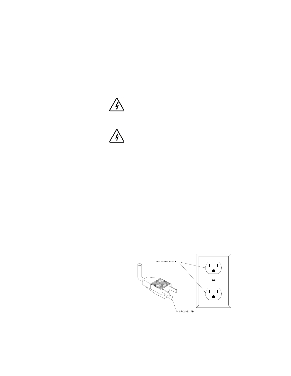
The non explosion-proof model is for use on a nominal 120-volt circuit and has a
grounding plug that looks like the plug illustrated in the figure below. Make sure
that the product is connected to an outlet having the same configuration as the p lug.
No adapter should be used with this product.
Note: If product has a nameplate for nominal 220-vo lt circuit, make
sure the proper grounded outlet is used.
Figure 1. Grounding Methods

SETTING UP THE MIXER
10
Caution Under no circumstances should you modify the
plug if it does not fit the outlet. Check with a
qualified electrician or serviceman if you are not
sure how to ground this unit.
Supply Current
The table "Minimum Wire Gauge" (below) shows the recommended wire size for
home run lengths. NOTE: The smaller the gauge number, the heavier the wire.The
following chart is the wire gauge size required for the distance from the circuit box
to the grounded receptacle (for up to 15 amperes at 115V, 60 Hz). Smaller gauge
wire than shown on the table could result in a voltage drop that can effect the
operation of your unit.
Extension Cords
Extension cords for 220 VAC models are not recommended. If an extension cord is
to be used, it should not be combined with others. Use only a 3-wire extension cord
that has a 3-pole grounding plug. Power should be provided by a 3-pole receptacle
that will accept the plug on the product. Make sure that your extension cord is in
good condition. It must have # 14 AWG conductors up to 25 feet long. An
extension cord no longer than 50 feet is permissible provided it has conductors of at
least # 12 AWG. It must be heavy enough to carry the current your product will
draw. An undersized cord will cause a drop in line voltage resulting in loss of
power and overheating.
Distance (feet) 25 50 100 150 20 250 300 400 500
Gauge Size
220V
14 14 12 10 10 8 8 6 6
Gauge Size
115V
14128664422
Table 1. Minimum Wire Gauge

SETTING UP THE MIXER
GyroMixer End User Guide 11
LEVELING
The customer must level the mixer. Although the unit is shipped on casters for ease
of positioning the mixer, all 4 feet must be extended firmly to the floor. Variations
on the floor will necessitate adjusting the leveling feet to ensure proper operation
and to minimize vibration.
CAUTION Improper leveling may cause severe vibration
while the mixer is operating.
1. Roll the unit into its intended location.
2. Lower the four (4) leveli ng feet to the ground. Each of the four leveling
feet can be adjusted independently. Using the front of the mixer as a
position guide, turn the foot in a clockwise direction to lengthen, or in a
counter-clockwise direction to shorten.
IMPORTANT: The feet should carry the load; not the casters.
Check the stability of the mixer on the floor by making
sure that the mixer is resting on all four feet, not on its
casters. All casters must rotate freely.
3. Verify that the mixer is level by gripping its sides and gently attempting
to rock the machine. It should not move.
4. Lock the leveling feet into place by tightening the upper locknuts to the
mixer bottom with a 3/4" wrench.
Note: Should additional leveling be necessary, loosen the upper
locknuts and repeat steps 2 - 3.

SETTING UP THE MIXER
12
OPERATIONAL TEST
1. Verify that the power is connected to the mixer.
2. Open the mixer's sliding door.
3. Slide a container into the groove on the table.
Note: Rotate the clamp handle counter clockwise first to open
the clamp arms.
4. Rotate the bail shield over the container bail. Remove the shield for
containers smaller than one gallon.
Note: Failure to properly position the bail shield on containers
larger than one gallon may damage the mixer.
5. With both hands, turn the knobs on the crank handle clockwise until
snug. Continue turning until the crank handle suddenly slips.
6. Close the sliding door.
7. Set the timer. (Not required for Explosion-Proof model)
Note: Make sure that the emergency stop switch is in the "on"
(pulled out) position. This can be done by turning the
knob counter clockwise.
8. Move the power lever to the ON position. The unit should cycle
automatically with minimum vibration. If vibration of the cabinet
occurs, immediately depress the emergency stop switch.
Note: Vibrations may occur because the unit is not properly
leveled. Try rocking the unit to make sure that all four feet
are solidly contacting the floor. Readjust the feet if
necessary. After the feet have been adjusted, reset the
emergency stop switch and continue.
9. When the test is complete, move the power lever to the OFF position.
10. Open the sliding door.
11. Rotate the mechanism to an upright locking position.
12. Use the knob marked "open" to turn the crank handle in the direction of
the arrow until the container is free. If necessary rotate the bail shield
away from the bail and remove the container.
OPERATIONS
GyroMixer End User Guide 13
OPERATIONS
Before operating the paint mixer, carefully read the Warnings and Cautions in the
Safety section and on the mixer, then follow these steps:
OPERATING THE MIXER
1. Open the mixer's sliding door.
2. Slid e a co ntainer into the groo ve on the table. Rotate the clamp handle
counter clockwise to open the clamp arms.
3. Position the bail shield over the container bail by rotating the upper
plate. The bail shield must be removed for containers smaller than
7-1/4" high.
Note: In situations involving frequent mixing of large and small
(less then 1-gallon) containers, a special elastic cord is
supplied to fasten the bail to the can.
CAUTION Failure to properly position the bail shield on
containers larger than one gallon may damage
the mixer. It is normal for the bail to move freely
behind the shield.
4. With both hands, turn the knobs on the crank handle clockwise until
snug. Continue turning until the crank handle suddenly slips.
5. Close the sliding door.
6. Set the timer. (Not required for Explosion-Proof model)
7. Make sure that the emer gency stop switch is in the "on" position (pulled
out). This can be done by turning the knob counter clockwise.
EXPLOSION-PROOF MODEL
• The timer is set to 1-1/2 minutes at the factory before
shipment.
• See the Service Section of this manual or consult an
authorized Service Center to adjust the timer.
OPERATIONS
14
8. Move the POWER lever to the ON position.
WARNING A safety interlock system prevents the operator
from opening the sliding door while the mixer is
running. Do not attempt to open the door while
the mixer is running.
• For an emergency stop in mid-cycle, push the EMERGENCY STOP
button.
• If vibrations occur, turn off the machine and refer to the leveling
section of this manual.
9. When the mixer has completed its cycle, move the power lever to the
OFF position.
10. Open the sliding door.
11. Rotate the mechanism to an upright locking position.
12. Use the knob marked "open" to turn the crank handle in the direction of
the arrow until the container is free. If necessary rotate the bail shield
away from the bail and remove the container.
MIX TIMES
Material Quantities Approx. Mix Times *
Latex Paint 5 gal, 15L, 20L 15 - 30 seconds
Latex Paint 1 gal, 5L or less 30 - 60 seconds
Gum-Based Paint 20L 1 - 1.5 minutes
Stucco** 5 gal, 15L, 20L 1.5 - 2 minutes
* Actual mixing times may vary depending upon material viscosity, container
size, head space, and colorant.
** When mixing stucco or other textured coatings, tip the container upside-
down, then upright again before adding colorant.

MAINTENANCE
GyroMixer End User Guide 15
MAINTENANCE
The Miller GyroMixer is designed for simple maintenance. For example, the motor
contains sealed bearings which require no lubrication.
To ensure safe, dependable operation of the paint mixer, follow the maintenance
schedule detailed below.
WARNING Always unplug the power cord when performing
maintenance procedures
.
DAILY
Immediately clean up spills with mild soap and water. A 3/4” drain pipe is
located under the front shelf to aid in cleanup.
• Thoroughly remove soap film with clean, lukewarm water.
• DO NOT clean this mixer with flammable solvents.
WEEKLY
• Inspect electrical cord for damage or wear.
• Clean/scape debris from sliding door track to maintain smooth operation.
MONTHLY
• Clean debris from guide rods for the upper and lower moving arms.
• Lubricate the guide rods and lead screws with graphite grease or
medium weight oil. NO grease or oil should touch the belts or pulleys.
 Loading...