

Page 1

FAST & FLUID MANAGEMENT
Blendorama series II
ENGLISH
Page 2

© Fast & Fluid Management, Blendorama series II
p1
Page 3

© Fast & Fluid Management, Blendorama series II
Table of Contents
Blendorama series II manual (EN) 3
Introduction, Conditions of Sale & Warranty 3
Safety instructions 6
Installation 7
Operation 10
Preventitive maintenance 17
General maintenance 21
Troubleshooting 38
Service Agents 39
Specificaties 40
Wiring diagram 41
p2
Page 4

© Fast & Fluid Management, Blendorama series II
Blendorama series II manual (EN)
Introduction, Conditions of Sale & Warranty
A - Introduction
By selecting a Fast & Fluid Management Color Dispenser you have opted for a product which is the result of
intensive research. Top-quality components, craftsmanship and a modern ergonomic design all serve to
guarantee a long service life and a high degree of user friendliness.
Blendorama Colorant Dispensers have been designed for long life and will withstand the normal wear expected
during use in plant or in store. However, each is a precision machined metering device and should be treated
accordingly
The basic unit of your dispensing system is represented as “Y” (except for metric and hybrid systems), and the
volume of this unit (approx. one fluid ounce) has been determined by the paint manufacturer.
The “Y” unit is further divided into (usually) 32, 48 or 64 sub-units. The basic unit of the metric dispenser is
one millilitre.
With the exception of Models 22/23XC, all feature a small bore inner pump to dispense small amounts of
colorant very accurately. The 1/64, 1/48 or millilitre units are divided further for this inner pump.
B - Standard Terms & Conditions of Sale
1. Application of Terms
These terms and conditions apply to every sale of a Blendorama Colorant Dispenser and Blendormix mixers
and each and every component part thereof ("the Product") by Fast & Fluid Management Australia ("the
Sellers) or any of its related companies to a Buyer and in the event that such Buyer purchases the Product
for resale, such resale shall be effected on the terms and conditions set out herein, except for price, and
such resale shall be deemed to be effected on such terms and conditions in the name and on behalf of the
parties to such resale transaction only, save for the Warranty contained in paragraph 6 which is given in the
name and on behalf of the Seller only.
2. Passing of Risk - transfer of title in the product
Prices are quoted ex-works. The risk of loss or damage to the Product shall pass to the Buyer in the case of a
contract for supply of the Product immediately upon delivery either to the Buyer or a nominated carrier for
transportation to the Buyer or to a place or site nominated by the Buyer or at the direction of the Buyer.
Such delivery shall be deemed to be delivery to the Buyer and acceptance by the Buyer of the Product
whether or not the Buyer is present at the time of delivery to sign a receipt for the Product. Notwithstanding
the foregoing property in and title to the Product shall not pass to the Buyer until payment in full for the
Product has been received by the Seller.
3. Delivery Time frame
Any date(s) given to the Buyer by the Seller for delivery shall be regarded as estimates only and while the
Seller shall use its best endeavours to meet such dates the Buyer agrees that no liability shall attach to the
Seller for any loss or damage, direct or consequential arising out of any delay in delivery or for non-delivery
from any cause whatsoever. If for any cause beyond the Seller's control, the Seller is unable to deliver
either within a reasonable time or at all, the contract shall be voidable at the Seller's option with no right of
either party to claim any damages against the other.
4. Sole Terms
These terms and conditions constitute the entire agreement for sale of the Product between the Seller and
the Buyer and shall prevail over any differing terms and conditions incorporated or purported to be
incorporated into the sale of the Product by the Buyer or by the Seller or otherwise alleged to have been
agreed and shall only be varied modified or rescinded by written agreement of the Seller.
p3
Page 5

© Fast & Fluid Management, Blendorama series II
5. Limitation of Liability
Subject to Paragraph 6 of these terms and conditions and in particular sub-paragraph 6.7 hereof the seller
shall neither be subject to nor incur, and the Buyer releases the Seller from any claim or liability (including
consequential loss or damage, loss or use or profit) by reason of delay, defective or faulty components or
materials or workmanship, negligence, or any act, matter or thing done admitted or omitted by the Seller or
by reason of the unsuitability of the Product for the Buyer's , purpose and the Buyer acknowledges that it did
not rely on the skill or judgement of the Seller in selecting and ordering the Product for the purpose for
which the same was required by the Buyers.
5.1 Product return
Subject to paragraph 6 hereof or as otherwise agreed by the Seller the Buyer may not return the Product or
any part or parts thereof after delivery has been effected. Any claim or claims for return of the Product or
any Parts thereof must be made within 30 days of delivery of the Product to the Buyer.
6.6.8 improper observance of the Daily Routine care instructions in the Booklet;
6.6.9 improper use in discharging the pump without observing the instructions in the Booklet;\
6.6.10 improper observance of the instructions in the Booklet;
6.6.11 improper observance of the Canister Drive maintenance instructions in the Booklet;
6.6.12 improper observance of the servicing of replacement parts instructions in the Booklet.
6. Warranty
The Seller hereby warrants to the Buyer that the Product will be free from defects in materials and
workmanship in normal use, service and operation for a period of twelve (12) months from the date of
delivery effected by the Seller or one of its authorised Distributors to the Buyer.
6.1 Warranty Limitations (1)
The Product is supplied subject to this Warranty only and liability arising out of or in respect of the supply,
resupply, use or re-use whether singularly or otherwise of the Product howsoever arising and whether in
respect of consequential loss or otherwise and including any other liability the Seller may otherwise have
had by virtue of any representation warranty condition or term (whether express or implied by law) is
hereby excluded.
6.2 Warranty Limitations (2)
Any liability incurred by the Seller to the Buyer is limited to the replacement of the Product or (at the
Sel1er's option) refund of the price paid by the Buyer, in particular does not extend to consequential loss
and is conditional upon the Buyer within 30 days of delivery making a written claim to the Seller setting out
the full particulars of any such claim. The transportation costs both ways are to be paid in full by the Buyer.
6.3 Claims Procedure
In the event of any defect arising the Buyer must notify the Seller or one of its authorised distributors in
writing and must establish to the reasonable satisfaction of the Seller or an authorised Distributor the date
of delivery of the Product by way of invoice or receipt and particulars delineated in the relevant part of this
Warranty
6.4 Future Modifications.
The Seller may make such modifications to any existing or future models of the Product as it may deem
necessary without incurring any obligation to incorporate such modifications in any Product(s) previously
sold or to which this Warranty may relate.
6.5 Sole Warranty
Subject to sub-paragraph 6.6 hereof, the obligations of the Seller or any authorised Distributor under this
Warranty are limited to those contained above ant this Warranty is the only Warranty made by the Seller
and is exclusively and expressly in lieu of all other warranties permitted to be excluded by law, whether
these warranties are express or implied, under the common law or by statute and the terms of the Warranty
may not be modified by any person, firm or corporation other than the Seller.
p4
Page 6

© Fast & Fluid Management, Blendorama series II
6.6 Warranty Exclusions
Subject to sub-paragraph 6.7 hereof this Warranty does not extend and the Seller or an authorised
Distributor will be relieved of all and any obligations, responsibilities and liabilities (direct or consequential)
in the event that defects in or malfunctions of the Product are directly or indirectly due to or result from:
6.6.1 lack of proper maintenance or care;
6.6.2 unreasonable or incorrect use, for a purpose other than that for which it was designed;
6.6.3 faulty setting up which is not carried out in accordance with the directions in the Blendorama
Booklet (''the Booklet");
6.6.4 failure to observe any other instruction or directions provided with the Product or given to the
Buyer by the Seller;
6.6.5 modifications or repairs made or attempted to be made by any unauthorised person;
6.6.6 improper use in operating the Product without observing the instructions in the Booklet
6.6.7 improper use in discharging the pump without observing the instructions in the Booklet;
6.6.8 improper observance of the Daily Routine care instructions in the Booklet;
6.6.9 improper use in discharging the pump without observing the instructions in the Booklet;
6.6.10 improper observance of the instructions in the Booklet;
6.6.11 improper observance of the Canister Drive maintenance instructions in the Booklet;
6.6.12 improper observance of the servicing of replacement parts instructions in the Booklet.
6.7 Statutory Warranties - The Product
It is expressly provided that this Warranty or any terms or conditions contained in it or other statement(s)
contained in these terms and conditions and Warranty, the Booklet or other literature given to the Buyer
shall not be read or applied so as to purport to exclude restrict or modify or have the effect of excluding,
restricting or modifying the application in relation to the supply of the Product of all or any of the provisions
of Division 2 and 2A of Part V of the Trade Practices Act 1974 ("The Act”) as amended or the exercise of a
right conferred by such a provision or any liability of the Seller or its Authorised Distributors for breach of a
condition or warranty implied by such provisions or any other conditions or warranties implied by any
relevant State Act or Territorial Ordinance or by the general law and which by law cannot be excluded,
restricted or modified PROVIDED THAT to the extent that The Act permits the Seller to limit its liability for
a breach of a condition or warranty implied by The Act, the liability of the Seller for such breach shall be
limited to the payment of the cost of replacing the Product or acquiring equivalent Product, or of repairing
the Product.
7. Product - In Store - Set Up
The Seller shall not be liable for any loss or damage caused directly or indirectly by:
Any damage to or deterioration in the conditions of the Product occurring after delivery to the Buyer and
prior to the setting up of the product;
any damage to the Product due to incorrect support or obstruction in setting up the Product;
any damage caused by the Product due to incorrect support or obstruction in setting up the Product.
p5
Page 7

© Fast & Fluid Management, Blendorama series II
Safety instructions
A - General safety instructions
Attention! Before installing the equipment, please read this instruction
manual carefully. This will increase your personal safety and prevent
unnecessary damage to the machine.
The manufacturer accepts no liability if the instructions below are not followed:
If a machine has been damaged (during transport, for example), do not attempt to set it in operation.
1.
When in doubt, first contact either your supplier or the F&FM service department.
The equipment should be positioned and connected up in strict accordance with the installation instructions.
2.
All local safety regulations and ordinances should be observed.
3.
The machine may be connected only to a 230/240V/50/60Hz or 110V/50/60HZ earthed wall socket
4.
installed in accordance with the regulations.
Users should ensure that the machine is kept in good condition. Defective components should be replaced.
5.
In order to prevent physical injury, the doors should be closed and the paneling fitted during normal use.
6.
All service activities (other than routine maintenance and adjustments) may only be carried out by
7.
qualified technicians. Ensure that the mains lead is always kept unplugged while repairs are being carried
out.
B - Specific warnings in this manual
Attention! MOVING PARTS CAN CAUSE INJURY. Always turn off power at
the wall socket before accessing moving parts.
p6
Page 8
© Fast & Fluid Management, Blendorama series II
Installation
A - Unpacking the dispenser
The box(es) you have received contain:
1 x Machine Base Assembly (for floorstand models)
1 x Turntable Assembly (This may be already assembled onto the base)
x Colorant Canisters, each with a lid, attached pump and fixing screws
1 x Operation Manual
A plastic bag or box containing:
1 x Allen Key for Pump Calibration (Note: Pumps preset in factory)
1 x No. 2 Phillips head screwdriver (for attaching canisters)
1 x ¼” spanner (for remote canister bracket attachement)
2 x Valve Inserts with "O" Rings
1 x Valve Insert Wrench (to enable pump to be removed from canister)
1 x Outer Piston Seal Kit complete with reusable Assembly Tool
2 x Nozzle Wiper Arms (with pads)
3 x Nozzles (larger bore)
3 x Nozzles (smaller bore)
1 x Inner Piston complete with reusable Assembly Tool
If any of these parts are missing, contact your supplier of F&FM immediately.
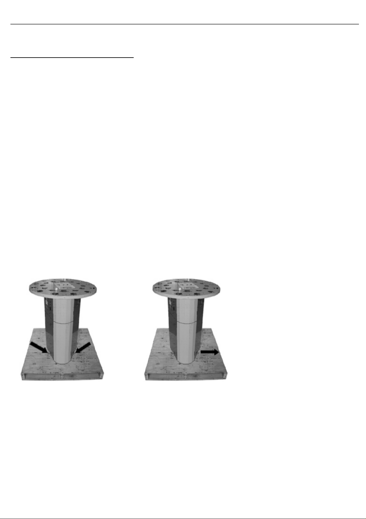
Step 1 - Detach the dispenser from its transport
skid
>
Unscrew the 2 transport
screws connecting the
machine to the skid
Carefully maneuver the
machine off the skid
p7
Page 9
© Fast & Fluid Management, Blendorama series II
B - Installing the canisters
Please note that this procedure is used for all canister sizes, although only
1.75L (22P) canisters are shown here. Other canister assemblies will vary
in size and appearance, however the procedure remains the same.
Connecting tubes are sized specifically for each canister and turntable size
– please do not mix between different models.
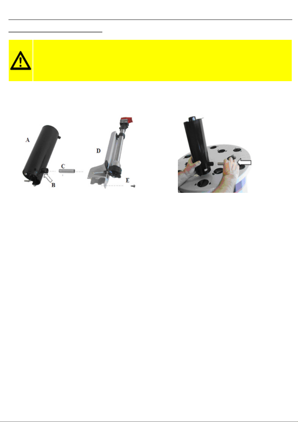
Step 1 - Prepare and install the inner ring of canisters.
>
(1) Select the parts used in an inner canister
assembly:
(A) canister with bush (B) at base
(C) connecting tube
(D) remote bracket and pump assembly
(E) washer collar self-tapping screw
(2) Firmly push the
connecting tube into the
bush.
p8
Page 10

© Fast & Fluid Management, Blendorama series II
> >
(3) Firmly push the canister
and connecting tube into the
remote bracket and pump
assembly.
(4) Fit this assembly to the
turntable. Canister screws
(already fitted to the
canister) fit into the inner
ring location keyholes and
the remote bracket fits into
the 4 slots simultaneously.
Push firmly into position.
Step 2 - Prepare and install the outer ring of canisters.
> >
(5) Secure the inner ring
canister assembly in position
with the washer collar
self-tapping screw
(provided) using either a
standard screwdriver or a
socket head (1/4” or 7mm).
(6) Repeat (2) to (5) for all
other inner ring canister
assemblies.
(1) Select the outer ring
canister assembly.
(2) Fit the canister screws
into the outer ring of keyhole
slots on the turntable. Push
firmly into position.
p9
(3) Locate the 2 guide holes
directly below each canister
and fasten the screws
(already located in canister)
with a Philips (No. 2)
screwdriver.
(4) Repeat steps (2) to (3)
for all other outer ring
canister assemblies.
Page 11
© Fast & Fluid Management, Blendorama series II
Operation
A - First time operation
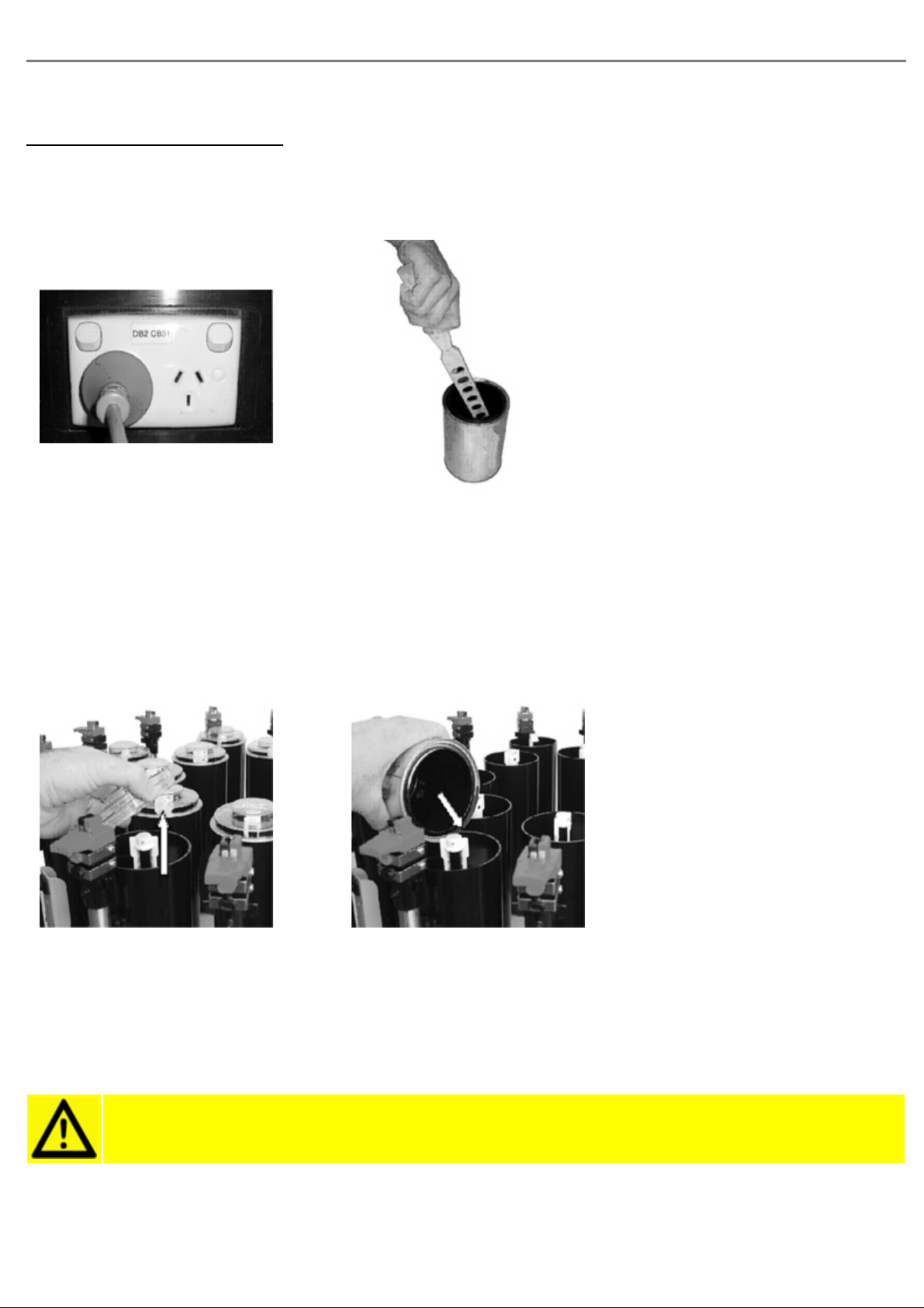
Step 4 - Preparing the dispenser
> >
Ensure that the machine is
switched off at the wall
socket
Remove the lids from all
canisters
>
Stir each can of colorant
thoroughly with a flat
bottomed paddle or palette
knife to reincorporate any
settled pigment
Pour the contents of each
colorant can into the correct
canister. Discard the
colorant can and replace the
canister lid
Ensure that the machine is
adequately supported and
clear of obstructions
Attention! Always wear eye protection when handling colorants
p10
Page 12
© Fast & Fluid Management, Blendorama series II
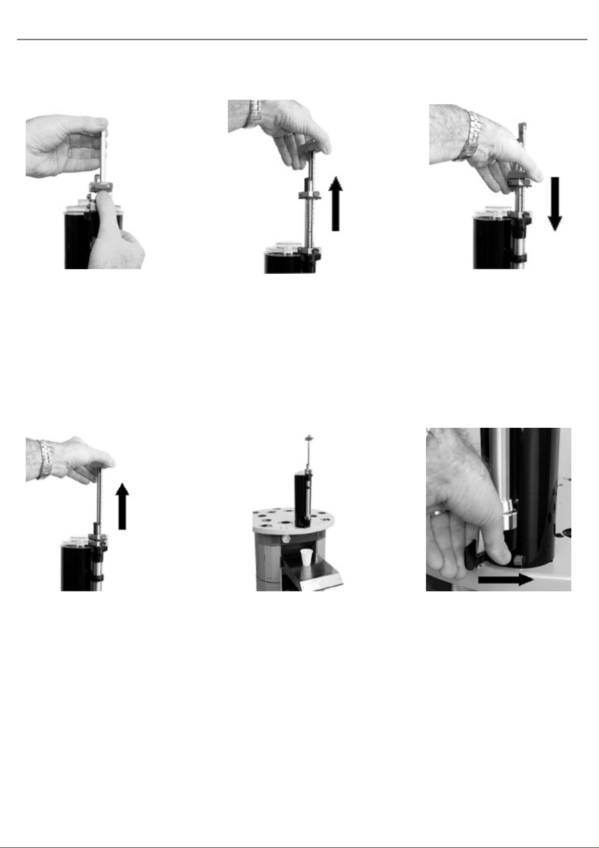
Step 2 - Purging the pumps
> >
Set the gauge or gauges of
each pump to its halfway
point by operating the spring
loaded button then lifting the
gauge by its handle
Step 3 - Purging the valve
> >
Without operating the valve
lever lift the red pump
handle to its maximum
travel (this draws the
colorant into the canister)
Discharge the colorant back
into the canister by
depressing the red pump
handle fully. Repeat this
process 30 times.
Lift the red pump handle to
its maximum travel
Place a clean can or paper
cup under the dispensing
nozzle
p11
Hold the valve lever open by
pulling the spring loaded
lever forward its full travel
Page 13

© Fast & Fluid Management, Blendorama series II
> >
Push the red pump handle
down fully to dispense
colorant into the cup
Release the valve lever Repeat this process until the
Step 4 - Check the effectiveness of the purge
> >
Open the valve lever
without operating the
pump. A small drop of
colorant will appear at the
nozzle
Release the valve lever
slowly and the drop will
withdraw into the nozzle
colorant emerges as an
unbroken stream
Repeat this process 10
times. If the drop of
colorant at the nozzle grows
appreciably with each
opening of the valve lever
and/or it drops from the
nozzle into the cup, then air
is still in the system and
steps 2 & 3 should be
repeated
Repeat this process for all
canisters.
Attention! For dispensers fitted with electronic timers, it is important that
the machine be switch on at all times unless topping up canisters.
Attention! For manual agitation type dispensers, it is good practice to
agitate the colorant twice daily for four (4) minutes.
p12
Page 14
© Fast & Fluid Management, Blendorama series II
B - General use of the dispenser
Step 1 - Select the color, base and can size
> >
Identify the color you wish
to supply either by name or
number
Step 2 - Position the
can
Look up the tint formula and
note the Tint Base required
Identify the quantity
required (can size)
Place the can on the
appropriate can shelf. Adjust
the height of the upper can
shelf (floorstand models )if
necessary
p13
Page 15

© Fast & Fluid Management, Blendorama series II
Step 3 - Bring canister to the correct position
>
Depress and hold the detent
lever to release the
turntable. You can lock the
detent lever in the release
position by pushing it
sideways.
When rotating the turntable, DO NOT use the canisters or pumps as
handles. Use the edge of the turntable.
Rotate the turntable so that
the pump of the appropriate
canister is directly over the
can. If the detent lever it
released it will lock the
canister into the correct
position. You may need to
move the turntable slightly
from side to side to allow
the locking pin to locate the
locking hole.
p14
Page 16

Step 4 - Set the Gauges
© Fast & Fluid Management, Blendorama series II
> >
According to the setting
required, operate the spring
loaded button to release the
gauge. The red knob is for
the red gauge and the black
knob is for the black gauge
Step 5 - Charge the pump
>
With the appropriate button
operated, lift the gauge to
the reading required.
The correct gauge setting is
shown when the figure
selected is fully exposed
above the RED handle and
the gauge release button
clicks firmly into place.
With the gauges correctly
set, slowly and gently lift the
red pump handle until both
red and black handles are
against the appropriate
gauge knobs
If the colorant level is too low, air can be sucked into the pump. If this
occurs, return the handle to the zero position, add sufficient colorant, and
purge the pumps and valve (see chapter IV, step 2 & 3)
Continue to hold this for a
few seconds to ensure the
pump is correctly filled with
colorant.
p15
Page 17

© Fast & Fluid Management, Blendorama series II
Step 6 - Discharge the pump
> >
While still holding the pump
handle in the raised
position, pull the
spring-loaded valve lever (at
the base of the pump)
forward its full travel
Holding the valve lever fully
forward, press the red
handle down with a smooth
and steady stroke until the
red handle is fully depressed.
Ensure that both the red and
black handles are fully
depressed against the end
cap. All the colorant has
now be discharged and the
valve lever can be released
Repeat the charging and
discharging process for each
colorant specified in the
formula
If you have to tint more than one container of the same color, leave the
gauges set at the required reading and simply recharge and discharge each
pump in turn in the order nominated by the tint formula.
p16
Page 18

Preventitive maintenance
A - Do’s & Don’ts
© Fast & Fluid Management, Blendorama series II
DO
DO
Keep the machine clean and display advertising promoting good housekeeping.
Keep this operation manual, Allen key, valve sleeve wrench and spare parts in a
convenient place to assist in regular maintenance
DON’T
DON’T
DON’T
Use the piston or valve assembly of each pump as a handle to rotate the
turntable. Instead, use the canister or edge of the turntable.
Attempt to replace the valve plate – if this is faulty, the whole valve assembly
must be replaced
Make any adjustments to the stirring timer. This unit has been factory set
and should only be adjusted by authorized personnel.
B - Daily maintenance
Clean the brush tray, refill canisters and run morning program
> >
Wipe down stand, canisters
and pumps with a moistened
cloth
Check nozzle outlets for dried
colorants.
If dried colorant is found to
be blocking the nozzle,
remove the nozzle by
pushing down on the top of
the nozzle.
p17
Page 19

© Fast & Fluid Management, Blendorama series II
>
Clean the nozzle using warm
soapy water
Refit the nozzle and dispense a
small amount of colorant
If the dispenser is not used on a regular daily basis, the following procedure
should be carried out.
> >
Check the level of colorant
and top up if required
Ensure that power is
connected to the dispenser
and turned on so that
automatic stirring occurs
Open and close each pump
valve 5 times
Purge the pumps (see chapter
IV, step 2 & 3) however only
operate the pump 5 times
>
Check the valve levers and nozzle
wiper arms for possible damage.
p18
Page 20

© Fast & Fluid Management, Blendorama series II
C - Weekly maintenance
If the dispenser is not used on a regular daily basis, the following procedure
should be carried out.
> >
Examine the machine for
loose canisters and loose
cylinder caps. Tighten if
necessary
Examine gauges for
damaged graduated scales
or worn holes and replace if
necessary
Raise the pump handle to its
maximum extension and
examine the pump shafts for
signs of colorant. This
indicates that the piston seal
will need replacement (see
Chapter VI - C,D,E)
p19
Page 21

© Fast & Fluid Management, Blendorama series II
D - Periodic maintenance
This maintenance should be carried out every 3 to 6 months depending
upon use.
> >
Inspect the function of the
valve and the canister for leaks
Remove stirrer paddle from
canister and wash the canister,
lid and stirrer paddle clean
Ensure that the machine is
disconnected from the power
source
> >
If required, tighten or replace
valve sleeve (with the wrench
supplied)
>
Remove canister from turntable
and drain colorant into a clean
container
Replace “O” ring seal
Reassemble and refit canister to
turntable
Attention! MOVING PARTS CAN CAUSE INJURY. Always turn off power
before accessing moving parts.
Return colorant to dispenser
and prepare the pump for
operation (see chapter IV-A)
p20
Page 22

© Fast & Fluid Management, Blendorama series II
General maintenance
A - Metalcal replacement (Models 22/23 XC)
Before replacing the metalcals, calibrate the plungers as per the calibration instructions. Also make sure that
the replacement metalcal is the correct one - check the part numbers.
> >
(1) Remove the red gauge
from the plunger.
(2) Peel the metalcal off the
gauge, and remove all traces
of adhesive (use a solvent if
necessary). Wipe dry.
> >
(3) Replace the gauge and
set to the zero (fully down)
position. The locking pin at
the rear of the pump should
be engaged in the first of the
small holes.
(4) Mark a line on the
gauge, level with the top of
the red handle. Use a fine
felt tip pen or pencil (or
scratch with a sharp object).
(5) Remove the gauge from
the pump and peel off the
adhesive backing.
p21
(6) Carefully place the “0”
line (the line below the
numeral) of the metalcal on
the marked line of the gauge.
Page 23

© Fast & Fluid Management, Blendorama series II
> >
(7) Once in position, press
the metalcal firmly onto the
gauge, ensuring it adheres
to the gauge along its full
length with no creases or
bubbles (use a clean cloth to
apply if necessary).
(8) Using a sharp knife or
blade cut any excess
metalcal off the end of the
gauge that may overlap the
red plastic handle.
(9) Refit the gauge to the
plunger.
B - Metalcal replacement (Models 22/23 XD/XE)
Before replacing the metalcals, calibrate the plungers as per the calibration instructions. Also make sure that
the replacement metalcal is the correct one - check the part numbers.
> >
(1) Remove both black and
red gauges.
(2) Peel the metalcals off
both the red and black
gauges, and remove all
traces of adhesive (use a
solvent if necessary). Wipe
dry.
p22
(3) Replace both gauges and
set to the zero (fully down)
position. The locking pin at
the rear of the pump should
be engaged in the first of the
small holes.
Page 24

© Fast & Fluid Management, Blendorama series II
> >
(4) Mark a line on the black
gauge, level with the top of
the red handle. Use a fine
felt tip pen or pencil (or
scratch with a sharp object).
(7) Once in position, press
the metalcal firmly onto the
gauge, ensuring it adheres
to the gauge along its full
length with no creases or
bubbles (use a clean cloth to
apply if necessary).
(5) Remove the gauge from
the pump and peel off the
adhesive backing.
> >
(8) Using a sharp knife or
blade cut any excess
metalcal off the end of the
gauge that may overlap the
black plastic handle.
(6) Carefully place the “0”
line (the line below the
numeral) of the metalcal on
the marked line of the gauge.
(9) Refit the gauge to the
plunger. Repeat steps (4)
through (9) for the inner
(red) gauge metalcal.
p23
Page 25

© Fast & Fluid Management, Blendorama series II
C - Metalcal replacement (Models 53 XB)
Before replacing the metalcals, calibrate the plungers as per the calibration instructions. Also make sure that
the replacement metalcal is the correct one - check the part numbers.
> >
(1) Remove both black and
red gauges.
(2) Peel the metalcals off
both the red and black
gauges, and remove all
traces of adhesive (use a
solvent if necessary). Wipe
dry.
> >
(3) Replace both gauges and
set to the fully down
position. Lift the black
(outer) gauge and engage
the locking pin in the 2nd
hole from the top.
(4) Mark a line on the black
gauge, level with the top of
the red handle. Use a fine
felt tip pen or pencil (or
scratch with a sharp object),
then remove the black gauge
from the pump.
(5) Peel the adhesive
backing off the black
metalcal.
p24
(6) Align the end of the
metalcal up against the
bottom edge of the gauge
knob, checking that the first
line of the metalcal (the line
below the first numeral)
lines up with the marked line
of the gauge (the metalcal is
cut to size before leaving the
factory).
Page 26

© Fast & Fluid Management, Blendorama series II
> >
(7) Once in position, press
the metalcal firmly onto the
gauge, ensuring it adheres
to the gauge along its full
length with no creases or
bubbles (use a clean cloth to
apply if necessary).
(8) Refit the black (outer)
gauge to the plunger and
remove the red (inner)
gauge from the pump.
> >
(9) Peel the adhesive
backing off the remaining
red metalcal.
(10) Align the end of the
metalcal up against the
bottom edge of the gauge
knob (the metalcal is cut to
size before leaving the
factory).
(11) Once in position, press
the metalcal firmly onto the
gauge, ensuring it adheres
to the gauge along its full
length with no creases or
bubbles (use a clean cloth to
apply if necessary).
p25
(12) Refit the red gauge to
the plunger.
Page 27

© Fast & Fluid Management, Blendorama series II
D - Metalcal replacement (Models 53 XD/XE)
Before replacing the metalcals, calibrate the plungers as per the calibration instructions. Also make sure that
the replacement metalcal is the correct one - check the part numbers.
> >
(1) Remove both black and
red gauges.
(2) Peel the metalcals off
both the red and black
gauges, and remove all
traces of adhesive (use a
solvent if necessary). Wipe
dry.
> >
(3) Replace both gauges and
set to the fully down
position. Lift the black
(outer) gauge and engage
the locking pin in the 2nd
hole from the top.
(4) Mark a line on the black
gauge, level with the top of
the red handle. Use a fine
felt tip pen or pencil (or
scratch with a sharp object),
then remove the black gauge
from the pump.
(5) Peel the adhesive
backing off the black
metalcal.
p26
(6) Align the end of the
metalcal up against the
bottom edge of the gauge
knob, checking that the first
line of the metalcal (the line
below the first numeral)
lines up with the marked line
of the gauge (the metalcal is
cut to size before leaving the
factory).
Page 28

© Fast & Fluid Management, Blendorama series II
> >
(7) Once in position, press
the metalcal firmly onto the
gauge, ensuring it adheres
to the gauge along its full
length with no creases or
bubbles (use a clean cloth to
apply if necessary).
(8) Refit the black (outer)
gauge to the plunger and
remove the red (inner)
gauge from the pump.
> >
(9) Peel the adhesive
backing off the remaining
red metalcal.
(10) Align the end of the
metalcal up against the
bottom edge of the gauge
knob (the metalcal is cut to
size before leaving the
factory).
(11) Once in position, press
the metalcal firmly onto the
gauge, ensuring it adheres
to the gauge along its full
length with no creases or
bubbles (use a clean cloth to
apply if necessary).
p27
(12) Refit the red gauge to
the plunger.
Page 29

© Fast & Fluid Management, Blendorama series II
E - Replacement of Piston Seals (Models 22/23 XC)
> >
(1) Loosen both grubscrews
in the cylinder of the end cap
(use Allen key provided) and
remove the plunger
assembly from the cylinder.
Remove the gauge and clean
all colourant from the
plunger assembly.
(2) Remove the old piston
retaining screw and discard
the screw, piston and
washer. Remove the new
piston from retainer.
> >
(3) Smear a trace of Loctite
262 on the screw thread and
secure the new piston with
the washer behind. Tighten
the screw only until the
piston can no longer be
rotated by hand.
(4) Holding the end cap (A)
in one hand, pull the red
handle (B) until the piston is
fully withdrawn inside the
end cap.
(5) After lightly oiling the
top inside edge of the
cylinder, position the plunger
assembly on the cylinder
with one hand. With the
palm of the other hand,
firmly push the red handle
down fully.
p28
(6) Lightly tighten the end
cap grubscrews, and refit the
gauge.
Page 30

© Fast & Fluid Management, Blendorama series II
F - Replacement of Piston Seals (Models 22/23 XD/XE)
Step 1 - Replacement of the inner piston
>
(1) Loosen both grubscrews
in the cylinder of the end cap
(use Allen key provided) and
remove the plunger
assembly from the cylinder.
Remove the gauges from the
plunger assembly, then
withdraw the inner plunger
assembly from the hollow
outer plunger shaft. Clean all
colourant from both plunger
assemblies.
(2) Using two pairs of pliers, grip
the inner end of the piston (A) with
one and the piston shaft with the
other. Unscrew the piston (using a
little heat if difficult) and discard.
(3) Apply Loctite 262 to the
internal thread of the piston shaft,
then screw the new piston
assembly in fully. Slide sleeve up
onto the shaft, tighten the piston
with pliers and replace the sleeve
over the piston.
p29
Page 31

© Fast & Fluid Management, Blendorama series II
Step 2 - Replacement of the outer piston
> >
(1) Using two spanners,
carefully undo the lower
piston nut. Discard the
piston but retain the nut.
(2) Remove the new piston
from retainer and fit to the
shaft curved end face up
(see picture). Replace the
front nut using a small drop
of Loctite 262 on thread.
Tighten the nut only until
the piston can no longer be
rotated by hand.
Step 3 - Returning plungers into cylinders
> >
(3) Holding the end cap (A)
in one hand, pull the outer
pump handle (B) until the
piston is fully withdrawn
inside the end cap.
(1) After lightly oiling the
top inside edge of the
cylinder, position the plunger
assembly on the cylinder
with one hand. With the
palm of the other hand,
firmly push the plunger
down fully.
(2) Remove the new piston
from retainer and fit to the
shaft curved end first.
Replace the front nut using a
small drop of Loctite 262 on
thread. Tighten the nut only
until the piston can no
longer be rotated by hand.
p30
(3) Remove the sleeve from
the inner piston and discard.
Lightly oil the inside edge of
the hollow outer piston shaft
and then gently ease the
piston inside. Refit the
gauges.
Page 32

© Fast & Fluid Management, Blendorama series II
G - Replacement of Piston Seals (Models 53 XB/XD/XE)
Step 1 - Replacement of the inner piston
>
(1) Undo the knurled nut
(A) holding the cylinder end
cap and remove the plunger
assembly (B) from the
cylinder. Remove both
gauges from the plunger
assembly, withdraw the
inner plunger assembly from
the hollow outer plunger
shaft and clean all colourant
from both plunger
assemblies.
(2) Using two pairs of pliers, grip
the inner end of the piston (A) with
one and the piston shaft with the
other. Unscrew the piston (using a
little heat if difficult) and discard.
(3) Apply Loctite 262 to the
internal thread of the piston shaft,
then screw the new piston
assembly in fully. Slide sleeve up
onto the shaft, tighten the piston
with pliers and replace the sleeve
over the piston.
p31
Page 33

© Fast & Fluid Management, Blendorama series II
Step 2 - Replacement of the outer piston
> >
(4) Fit the outer piston
assembly tool over the outer
piston shaft. Screw both
halves together then slide
the tool down over the
piston.
(5) Lightly oil the top inside
edge of cylinder and position
the tool containing the
plunger assembly on its rim.
Remove the screw from the
tool and force the piston
shaft through the split to
remove the tool.
(6) Refit the end cap onto
the top of the cylinder and
tighten the knurled nut.
Remove the sleeve from the
inner piston and discard.
Lightly oil the top inside
edge of hollow outer piston
shaft, gently ease the piston
inside. Refit all gauges.
p32
Page 34

© Fast & Fluid Management, Blendorama series II
H - Pump Calibration (Models 22/23 XC)
Recalibration of the pump is necessary if the original gauge has been replaced by another (for any reason) or if
the gauge scale detail (metalcal) is to be replaced. When recalibrating the pump, please leave the
pump/canister fixed in place on the machine.
Tools required:
1 x Allen (hex) key 3/32” A/F
1 x set of Feeler Gauges
>
(1) Using the Allen key provided, wind the
calibration screw up until it is entirely
within the red handle of the pump. Set the
gauge to the first non-zero position (see
the calibration chart or refer to your agent
for details).
(2) Wind the calibration screw down until
the desired clearance is achieved between
the small raised stop pad on the gauge
handle and the pump handle. The correct
clearance can be found on the calibration
chart (refer to your agent for details if
necessary). Measure the distance using
feeler gauges to confirm the clearance
accurately.
p33
Page 35

© Fast & Fluid Management, Blendorama series II
I - Pump Calibration (Models 22/23 XD/XE)
Recalibration of the pump is necessary if the original gauge has been replaced by another (for any reason) or if
the gauge scale detail (metalcal) is to be replaced. When recalibrating the pump, please leave the
pump/canister fixed in place on the machine.
Tools required:
1 x Allen (hex) key 3/32” A/F (originally supplied with the machine)
>
(1) To calibrate the outer
plunger, remove the inner
(red) gauge and inner (red)
plunger and set the outer
(black) gauge to the zero
position.
(2) Using the Allen key, undo both
calibration grubscrews until free movement
can be felt between the outer (black)
plunger handle and the outer (black)
gauge knob.
>
(3) Carefully wind one grubscrew down
until only slight movement is felt between
the outer pump handle and the gauge
knob. Then wind the other grubscrew
down until no free movement can be felt,
being careful not to over-adjust.
(4) To calibrate the inner (red)
plunger, refit the inner (red) gauge
and plunger removed in step (1).
Set the inner (red) gauge to zero.
p34
Page 36

© Fast & Fluid Management, Blendorama series II
>
(5) Using the Allen key, undo the
calibration grubscrew in the red pump
handle until free movement can be felt in the
handle. Carefully wind the grubscrew back
down until no free movement can be felt
between the red pump handle and the red
gauge knob. Be careful not to over-adjust.
(6) The pump is now calibrated.
p35
Page 37

© Fast & Fluid Management, Blendorama series II
J - Pump Calibration (Models 53 XB/XD/XE)
Recalibration of the pump is necessary if either of the original gauges have been replaced by another (for any
reason). It is not required if only a gauge scale detail (metalcal) has been replaced. When recalibrating the
pump, please leave the pump/canister fixed in place on the machine.
Tools required:
1 x Allen (hex) key 3/32” A/F
Step 1 - Outer pump calibration
>
(1) Calibrate the outer pump first
by removing the inner pump (red)
gauge and lifting the red pump
handle approximately 4” or
100mm. Lock the black outer pump
gauge into the top hole (zero
position). Using the Allen key,
undo the calibration grubscrew
until free movement can be felt
between the outer pump (black)
handle and the outer gauge knob.
(2) Carefully wind the grubscrew
down until no free movement is felt
between the outer pump handle and
the gauge knob, being careful not to
over-adjust. When correctly adjusted
there should be a slight binding felt
on the black gauge locking pin (as
the locking pin shaft enters the hole
in the gauge).
p36
Page 38

© Fast & Fluid Management, Blendorama series II
Step 2 - Inner pump calibration
>
(1) Calibrate the inner pump by lowering
red pump handle fully, then refitting the
inner (red) gauge and setting it to zero.
Undo the calibration grubscrew in the red
pump handle until the handle has
movement.
(2) Carefully wind the grubscrew
down until no free movement is felt
between the red pump handle and the
red gauge knob, being careful not to
over-adjust. When correctly adjusted
there should be a slight binding felt on
the red gauge locking pin (as the
locking pin shaft enters the hole in the
gauge).
p37
Page 39

© Fast & Fluid Management, Blendorama series II
Troubleshooting
A - Introduction
Before calling your machine supplier or Service Department, please check whether you can solve the problem
yourself. If you cannot, then call the Service Department for advice. Have the model number and serial
number at hand (these can be found on the sticker attached to service door at the side of the machine).
Attention! MOVING PARTS CAN CAUSE INJURY. Always turn off power
before accessing moving parts.
B - Problem solving
Symptom Cause Action
Colorant intermittently spurts
from the nozzle during
discharge
A drop of colorant falls from
the nozzle when the valve is
opened even when the pump is
not operated
The end cap twists or lifts
during operation
Canister is loose on turntable Loose fixing screws Tighten fixing screws with a philipps
Colorant appears on the piston
shaft, piston and/or gauges
Air bubbles in the colorant Operate the pump several times
without opening the valve to drive
the air back into the canister. Then
allow the colorant to sit for several
minutes to allow the bubbles to
escape.
Air is trapped in the cylinder
assembly
End-cap grub-screws are loose Lightly tighten the 2 grub-screws in
Worn seals Replace seals – refer to pages 32 to
Operate the pump several times
without opening the valve to drive
the air back into the canister. Then
allow the colorant to sit for several
minutes to allow the bubbles to
escape.
the end-cap (for 53 XB/XD/XE
tighten the end-cap sleeve) until the
end cap can no longer be twisted by
hand.
head screwdriver
35
Colorant does not dispense
easily
Colorant still does not dispense
easily
Colorant has hardened in the
canister and piston assembly
Agitation is not occurring No power to the dispenser Check that the unit is connected and
Nozzle blocked Remove nozzle and clean in warm
soapy water
High viscosity of colorant Increase the size of the nozzle
Canister and pump should be
removed, emptied, stripped and
cleaned thoroughly. Replenish only
with new colorant
that there is power to the outlet
p38
Page 40

© Fast & Fluid Management, Blendorama series II
Service Agents
A - Service Agents
For all service and repairs on Fast & Fluid Management products (including all warranty repairs), call the Fast
& Fluid Management Agent or Supplier. Within Australia, contact the service agent in your state or call the
Fast & Fluid management Service Hotline 1800 648584 or fax 02 42717306
Please make sure that you have the model number and serial number to hand. They can be found on the
nameplate on the machine.
NSW RW Palmer Electrical
Unit 17, 398 Marion Street, Bankstown, NSW, 2200
Phone : 02 97910337
Fax : 02 97910140
VIC Downer Electrical Pty Ltd
Factory 4, 33 Chambers Road, Altona North, VIC, 3025
Phone : 03 96449196
Fax : 03 96451644
QLD Downer Electrical Pty Ltd
35 Evans Road, Salisbury North, QLD, 4107
Phone : 07 32751244
Fax : 07 32752236
ACT Service On Site
140 Longmore Cr, Wanniassa, ACT
Phone : 02 62313196
WA Bridgemont Enterprises
PO Box 554, Joondalup, WA, 6919
Phone : 08 93008495
Fax : 08 93008495
SA Bob Winter
18 Metcalfe Ave, Modbury Heights, SA, 5092
Phone : 0418 426545
Fax : 08 83952255
TAS B.S.H Electrical Pty Ltd
213 Harrington Street, Hobart, TAS, 7000
Phone : 03 62310255
Fax : 03 62312691
New Zealand Kwikmix Engineering
4/12 Neil Park Drive, East Tamaki, NZ
Phone : 09 2732020
Fax : 09 2732024
p39
Page 41

© Fast & Fluid Management, Blendorama series II
Specificaties
Number of canisters Up to 24
Canister sizes 22/23 XC/XD/XE 1.75L Single canisters & 3.5L double
canisters
53 XB/XD/XE 2.5L single canisters & 5.0L double
canisters
Canister/stirrer (material) molded 100% acetal
Valves molded 100% acetal
Pump type piston pump
Pump sizes Inner ¼ ounce (22/23/53 - XD/XE) & 2 ounce (53XB)
Pump sizes Outer 2 ounce (22/23 - XC/XD/XE) & 5 ounce (53 –
XB/XD/XE)
Min. dispensing 1/384 fl.oz
Stirring timer Adjustable twin timer
Moveable upper can shelf Standard on floor model
Foldout lower canshelf Standard on floor model
Power supply 110V 50Hz/60Hz
230/240V 50Hz/60Hz
Specifications subject to change without prior notice.
p40
Page 42

© Fast & Fluid Management, Blendorama series II
Wiring diagram
A - Electrical wiring diagram – Twin Timer Version
B - Electrical wiring diagram – Clockwork Timer version
p41
Page 43

© Fast & Fluid Management, Blendorama series II
p42
Page 44

© Fast & Fluid Management, 2005
www.Fast-Fluid.com
 Loading...