

Page 1
Manual HP500 / HP800
V. 3.0
Fast & Fluid Management B.V.
PO Box 220
2170 AE Sassenheim
The Netherlands
www.fast-fluid.com
Page 2

© Fast & Fluid Management B.V.
This manual or parts thereof may not be reproduced, stored in a retrieval system, or transmitted, in any form or by any means,
electronic, mechanical, photocopying, recording, nor otherwise, without the prior written permission of Fast & Fluid
Management B.V.
This manual could contain technical inaccuracies or typographical errors.
Fast & Fluid Management B.V. reserves the right to revise this manual from time to time in the contents thereof without the
obligation of Fast & Fluid Management B.V. to notify any person of such revision or change.
Details and values given in this manual are average values and have been compiled with care. They are not binding, however,
and Fast & Fluid Management B.V. disclaims any liability for damage or detriments suffered as a result of reliance on the
information given herein or the use of products, processes or equipment to which this manual refers. no warranty is made that
the use of the information or of the products, processes or equipment to which this manual refers will not infridge any third
party’s patents or rights. The information given does not release the user from making their own experiments and tests.
2
Page 3

Table of contents HP500 / HP800 V. 3.0
Table of contents
1 About this manual.........................................................................................................5
1.1 How to work with the manual .......................................................................................... 6
1.2 Record of changes ......................................................................................................... 6
2 Safety .............................................................................................................................7
2.1 Intended use ................................................................................................................... 7
2.2 Liability ............................................................................................................................ 7
2.3 User qualification for installation ..................................................................................... 7
2.4 CE certification ............................................................................................................... 7
2.5 Safety symbols on the machine ...................................................................................... 8
2.6 Safety symbols in the manual ......................................................................................... 8
2.7 Disposal of the machine ................................................................................................. 9
3 Operator manual ......................................................................................................... 11
3.1 Description .................................................................................................................... 11
3.1.1 Overview of the machine.................................................................................... 11
3.1.2 Overview of the controls..................................................................................... 12
3.1.3 Options ............................................................................................................... 13
3.1.4 Type plate: serial number................................................................................... 14
3.1.5 Type plate: details .............................................................................................. 14
3.2 Operation ...................................................................................................................... 15
3.2.1 General dispensing procedure ........................................................................... 15
3.2.2 Place the can...................................................................................................... 15
3.2.3 Move up the can table ........................................................................................ 16
3.2.4 Move down the can table ................................................................................... 16
3.3 Maintenance ................................................................................................................. 16
3.3.1 General cleaning: after every dispensing operation ........................................... 16
3.3.2 Cleaning of the nozzle and the brush container: daily........................................ 17
3.3.3 Refilling of a canister .......................................................................................... 20
4 Installation ...................................................................................................................21
4.1 Unpack the machine ..................................................................................................... 21
4.1.1 Remove the cardboard....................................................................................... 21
4.1.2 Remove the plastic protection on the canisters.................................................. 21
4.1.3 Open the switch plate......................................................................................... 22
4.1.4 Remove the plastic protection on the switch plate ............................................. 22
4.1.5 Close the switch plate ........................................................................................ 22
4.1.6 Remove the corner panels ................................................................................. 23
4.1.7 Remove the transport brackets at the front ........................................................ 23
4.1.8 Remove the transport brackets at the rear......................................................... 23
4.1.9 Remove the wooden beams............................................................................... 24
3
Page 4

Table of contents HP500 / HP800 V. 3.0
4.2 Put the machine in position .......................................................................................... 24
4.2.1 Move the machine to the final location, with a fork-lift truck............................... 24
4.2.2 Move the machine to the final location, with a ramp (optional) .......................... 24
4.2.3 Level the machine.............................................................................................. 25
4.3 Install the computer ...................................................................................................... 25
4.3.1 Open the computer cover................................................................................... 25
4.3.2 Install the computer............................................................................................ 26
4.4 Turning on the machine ............................................................................................... 26
4.5 First use ....................................................................................................................... 26
5 Troubleshooting..........................................................................................................27
5.1 Contact service ............................................................................................................ 27
5.2 Troubleshooting guide .................................................................................................. 27
6 Technical data .............................................................................................................29
6.1 General specifications .................................................................................................. 29
6.2 Dimensions and mass .................................................................................................. 29
6.3 Ambient conditions ....................................................................................................... 30
6.4 Noise level .................................................................................................................... 30
6.5 Safety classifications .................................................................................................... 30
6.6 Electrical specifications ................................................................................................ 30
4
Page 5

About this manual HP500 / HP800 V. 3.0
1 About this manual
The manual shows the information necessary to:
-install
- operate
- perform basic maintenance
- correct small problems.
The HP500, the HP800 and all their versions are referred to in the manual as the ’machine’.
This manual contains the original instructions. The original language of the manual is English.
5
Page 6

About this manual HP500 / HP800 V. 3.0
1.1 How to work with the manual
1. Familiarize yourself with the structure and content.
2. Read the safety chapter in detail and make sure you
understand all the instructions. See § 2.
3. Carry out the actions completely and in the given sequence.
1.2 Record of changes
/i
Edition Editor Check Date Description
1.0 TB MB 12/2010 First edition
2.0 TB MB 01/2012 Included: punch and heating sensor options and HP800
3.0 ET MvDo 05/2012 Technical specifications: change of dimensions
6
Page 7

Safety HP500 / HP800 V. 3.0
2 Safety
WARNING
Read the manual before you install or use the machine. Failure to do so can result in personal
injury, death or property damage.
2.1 Intended use
The machine is designed to dispense colorants into a can. Any other use of the machine is strictly forbidden.
2.2 Liability
Fast & Fluid Management B.V. is not liable if you do not follow the rules below:
- Do not use a damaged machine. When you have doubts, contact your supplier or the service department of
Fast & Fluid Management B.V. See www.fast-fluid.com.
- Install and connect the machine according to the instructions in this manual.
- Observe all local safety regulations.
- Connect the machine to a grounded wall socket.
- Keep the machine in good condition. Make sure that defective parts are immediately replaced.
- Close the covers and make sure that all the panels are fitted.
- Replace parts only with original Fast & Fluid Management B.V. spare parts.
All maintenance beyond the scope of this manual must be carried out by a qualified service technician that Fast
& Fluid Management B.V. has trained and certified.
2.3 User qualification for installation
Only install the machine if you have written permission from the supplier of the machine.
2.4 CE certification
The machine is CE certified. It means that the machine complies with the essential requirements concerning
safety and hygiene. The directives that have been taken into consideration in the design are available on
www.fast-fluid.com
.
7
Page 8
Safety HP500 / HP800 V. 3.0
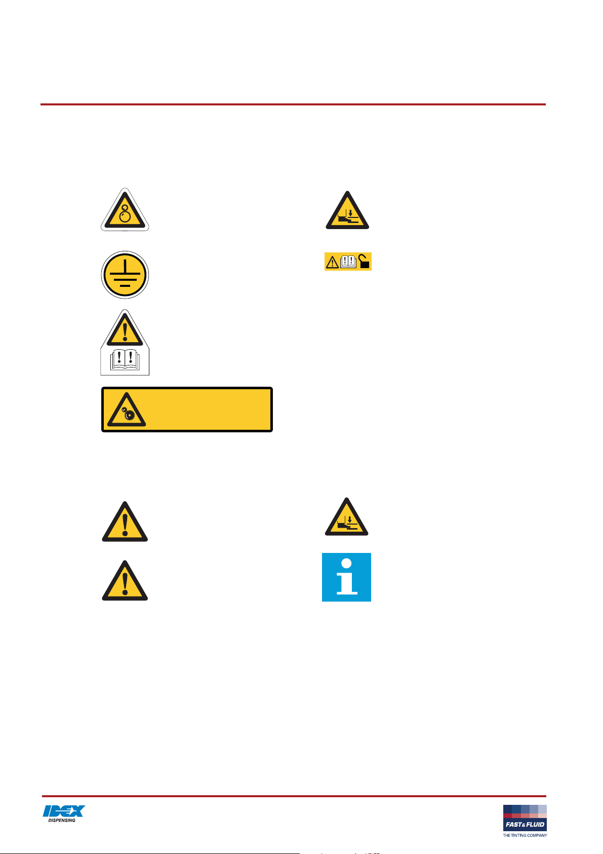
2.5 Safety symbols on the machine
/i
Moving parts hazard Pinch hazard foot
Grounding is necessary Read the manual before you open this
part. If you do not open this part, lock it.
Read the manual
Return this part to
its original position
2.6 Safety symbols in the manual
/i
WARNIN G
Can cause personal injury.
CAUTION
Can cause damage to the machine.
Return the part to its original position.
WARNING
Pinch hazard for your foot.
Note
Shows further information.
8
Page 9

Safety HP500 / HP800 V. 3.0
2.7 Disposal of the machine
1. Sort the machine, the accessories and the packaging for
environmentally friendly recycling.
2. Do not dispose of the machine into domestic waste. Dispose
of the machine according to local regulations.
3. Dispose of the canisters as chemical waste, according to the
local regulations.
9
Page 10

Safety HP500 / HP800 V. 3.0
10
Page 11
Operator manual HP500 / HP800 V. 3.0
3 Operator manual
3.1 Description
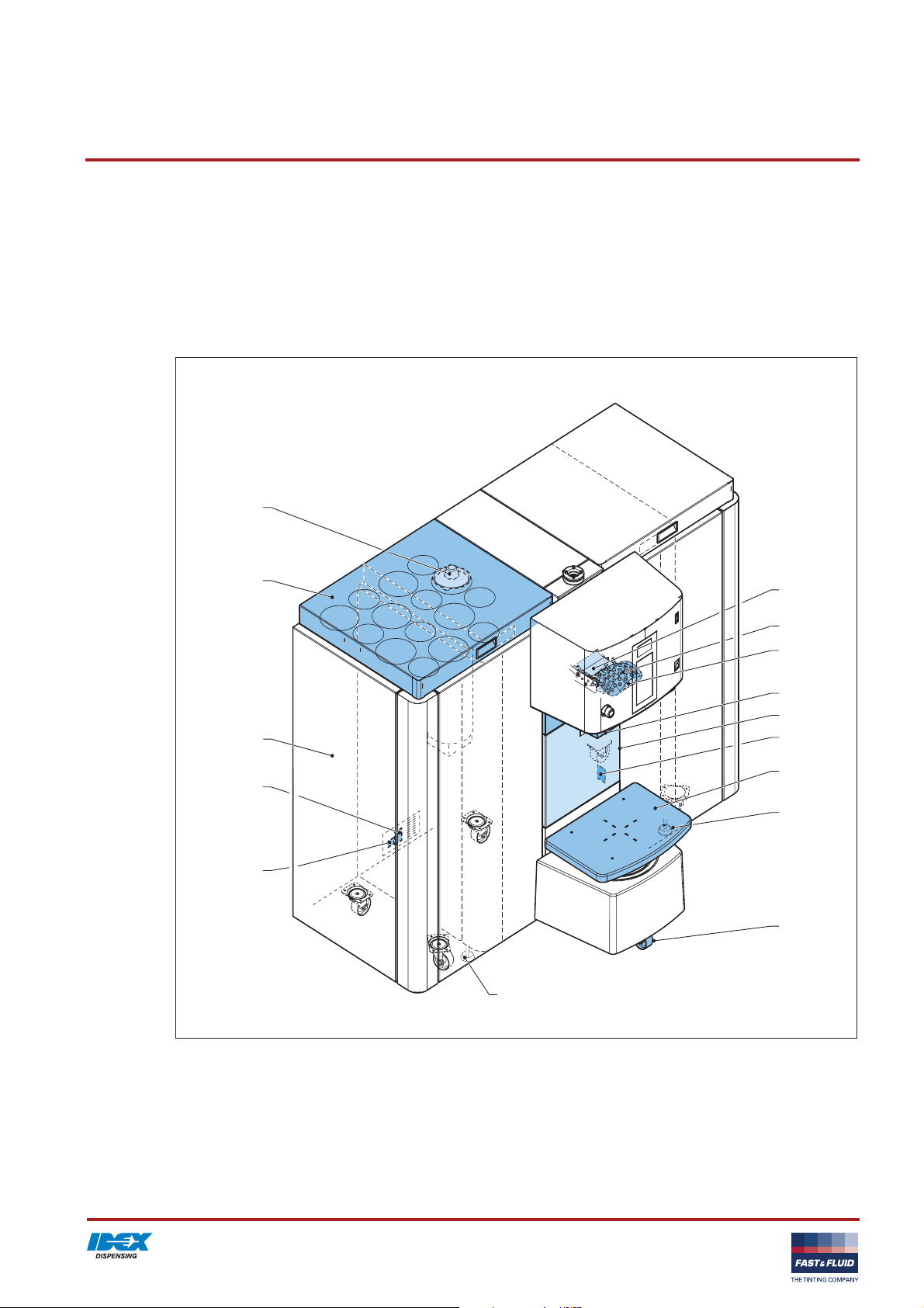
3.1.1 Overview of the machine
C
L
G
A
H
I
J
D
B
A
K
E
F
M(6x)
F
A: Top cover
B: Computer cover
C: Canister
D: Switch plate
E: Can table
F: Adjustable foot (2x)
G: Net entry
H: Brush container
I: Nozzle
J: Nozzle blade
K: Type plate: serial number (at the inside of the
computer compartment)
L: Type plate: details
M: Wheels
11
Page 12

Operator manual HP500 / HP800 V. 3.0
3.1.2 Overview of the controls
A
A: Can table switch
B: Emergency
C: Computer switch
D: Brush maintenance switch
C
B
D
12
Page 13
Operator manual HP500 / HP800 V. 3.0
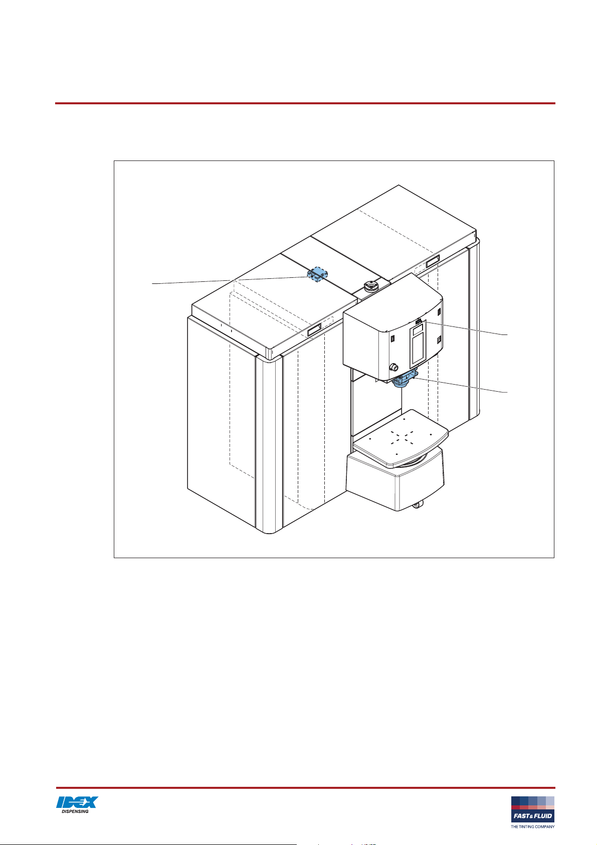
3.1.3 Options
A
C
A: Thermostate
B: Punch
C: Punch switch
B
13
Page 14

Operator manual HP500 / HP800 V. 3.0
3.1.4 Type plate: serial number
Fast & Fluid Management
IDEX Dispensing
&
FAST FLUID
THE TINTING COMPANY
P.O. Box 220
2170 AE Sassenheim
The Netherlands
Model
XXXXX-XXX
Prod. Week XX-XXXX
Serial No.
XXXXX-XX-XXXXXX
3.1.5 Type plate: details
Fast & Fluid Management
IDEX Dispensing
&
FAST FLUID
THE TINTING COMPANY
230 V 50/60 Hz 700 W
Model XXXXX-XXX
Serial no. XXXXX-XX-XXXXXX
Prod. week XX-XXXX
Mass XXX XX
Fuse XX XX
Patented families design
P.O. Box 220
2170 AE Sassenheim
The Netherlands
c
Made in XXXXXXXXX
14
Page 15
Operator manual HP500 / HP800 V. 3.0
3.2 Operation
WARNING
Only push the emergency stop in the case of a safety emergency.
Make sure that the problem is solved before you reset the emergency stop.
When you reset the emergency stop, the machine restarts automatically. When the machine is
operational, you hear ’beep beep’.
CAUTION
Do not remove the power from the machine. See § 4.4. The machine must stir the colorants
periodically.
Note
The computer switch only turns the computer on and off.
3.2.1 General dispensing procedure
For all the software instructions: see the software documentation.
1. Place the can. See § 3.2.2.
2. Move the can table up. See § 3.2.3.
3. Choose the recipe and dispense. See the software
documentation.
4. Move the can table down. See § 3.2.4.
5. Remove the can.
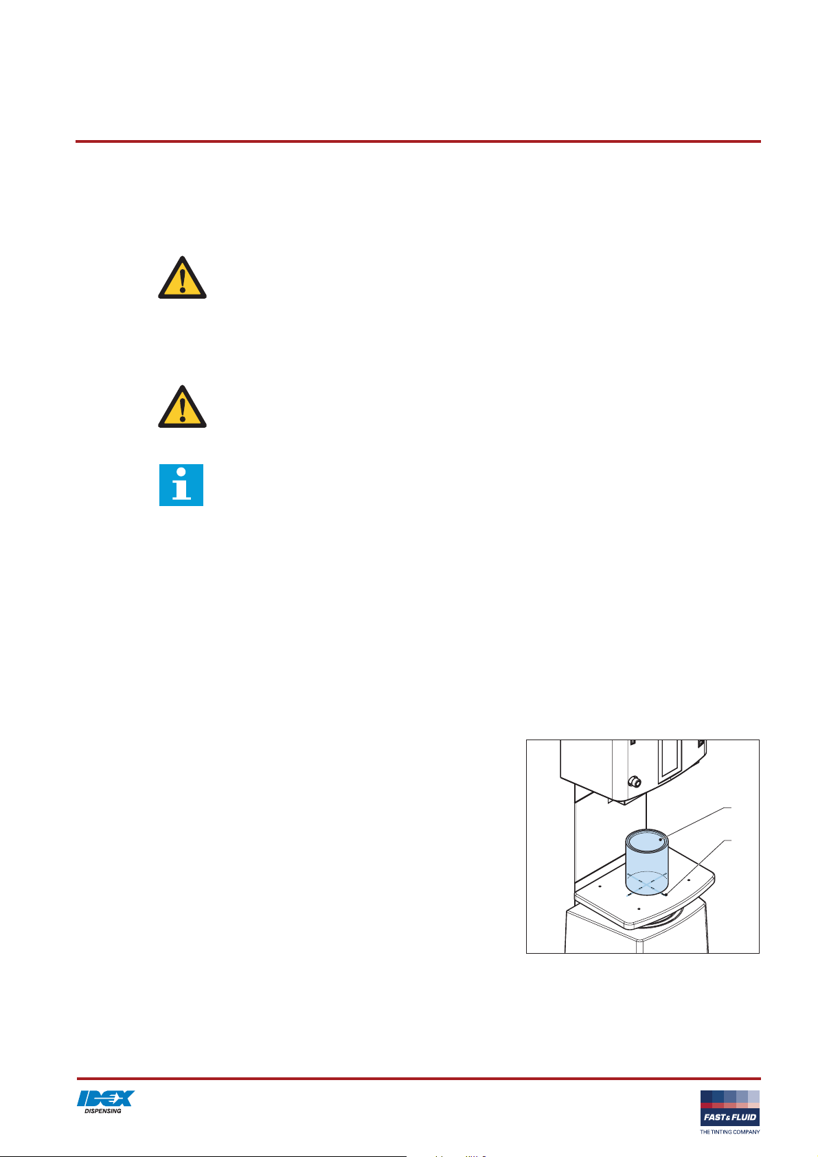
3.2.2 Place the can
1. Place the can (A) at the centre of the mark (B) on the can
table.
A
B
15
Page 16
Operator manual HP500 / HP800 V. 3.0
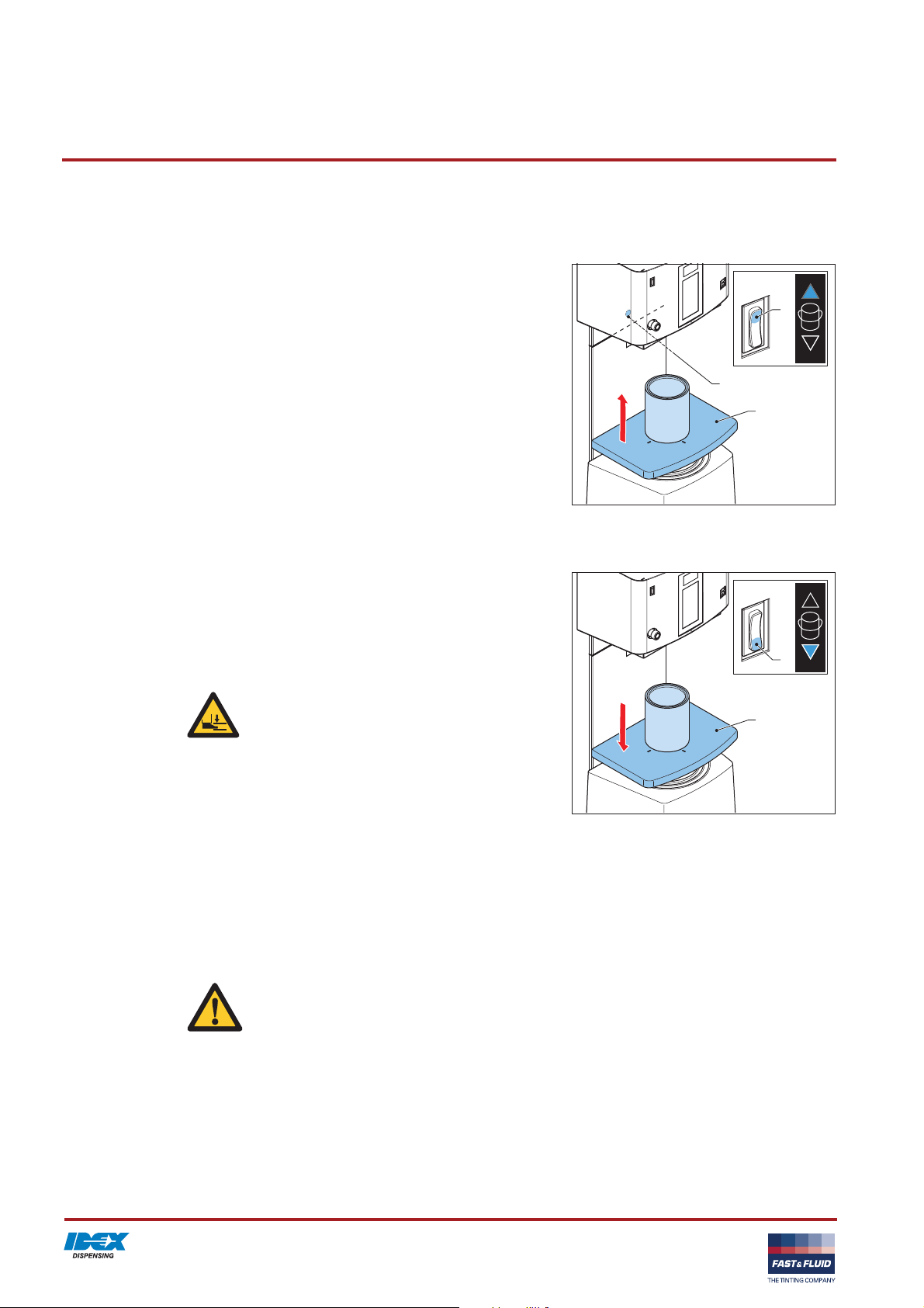
3.2.3 Move up the can table
1. Push and hold the upper part of the can table switch (A). The
can table (B) moves up and stops when the can is in front of
the can sensor (C).
2. After the can table stops, release the can table switch.
C
3.2.4 Move down the can table
A
B
1. Push and hold the lower part of the can table switch (A). The
can table (B) moves down.
2. When you can remove the can, release the can table switch.
If you hold the can table switch, the can table moves down to
a halt.
WARNING
Do not put your foot below the can table.
3.3 Maintenance
3.3.1 General cleaning: after every dispensing operation
1. Clean the machine with a cloth and remove all spilled colorant
or other liquid.
CAUTION
Do not use cleaning agents based on organic
solvents to clean painted or plastic parts of the
machine.
A
B
16
Page 17
Operator manual HP500 / HP800 V. 3.0
3.3.2 Cleaning of the nozzle and the brush container: daily
CAUTION
If you do not clean these items daily, severe pollution will occur.
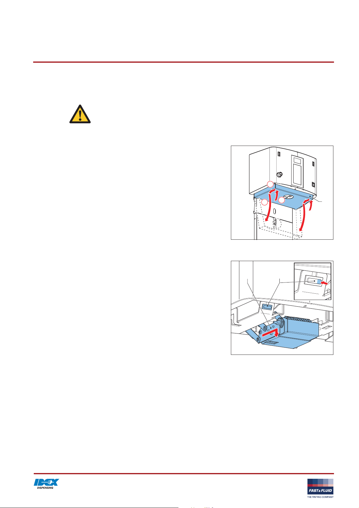
Open the switch plate
1. Move the front of the switch plate (A) upwards.
2. Push the switch plate backwards.
3. Turn the switch plate down.
2
Move down the brush unit
1. Push and hold the right part of the brush maintenance
switch (A). The brush unit (B) moves forward and then down.
2. After the brush unit stops, release the brush maintenance
switch.
1
3
B
A
A
17
Page 18
Operator manual HP500 / HP800 V. 3.0
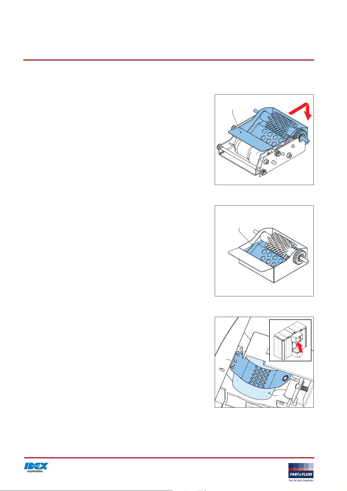
Remove the brush container
1. Remove the brush container (A).
A
Clean the brush container
1. Remove the liquid from the brush container. For the disposal
of the liquid, follow the local regulations.
2. Fill the brush container, with the liquid that your paint supplier
indicates, to the mark (A).
A
Examine the nozzle and clean if necessary
1. Examine the nozzle for contamination.
2. If necessary, clean the surface of the nozzle (A) and the
nozzle blade (B). Use a cloth.
18
B
A
Page 19

Operator manual HP500 / HP800 V. 3.0
Move up the brush unit
1. Install the brush container.
2. Push and hold the left part of the brush maintenance
switch (A). The brush unit moves up and then back.
3. After the brush unit stops, release the brush maintenance
switch.
Close the switch plate
1. Turn the switch plate (A) upwards.
2. Move the switch plate forwards.
3. Put the brackets of the switch plate (B) on the brackets (C) of
the sensor.
B
2
1
3
A
C
A
B
2x
C
19
Page 20

Operator manual HP500 / HP800 V. 3.0
3.3.3 Refilling of a canister
CAUTION
Make sure that the colorant level in the canister is correct. If a canister is empty, this can cause an
inaccurate dispensing and/or a recipe fault.
Note
The software checks the level of colorant in each canister. The software on the machine shows
when you need to refill a canister.
1. In the software, activate the fill canister option.
2. Open the top cover (A).
3. Remove the lid of the canister (B).
4. Add the colorant (C). Do not spill.
A
B
1
2
3
C
20
Page 21

Installation HP500 / HP800 V. 3.0
4 Installation
4.1 Unpack the machine
4.1.1 Remove the cardboard
1. Remove the cardboard and the plastic (A) from the outside of
the machine.
A
4.1.2 Remove the plastic protection on the canisters
1. Open the top cover (A).
2. Remove the plastic protection (B).
A
B
21
Page 22

Installation HP500 / HP800 V. 3.0
4.1.3 Open the switch plate
1. Move up the front of the switch plate (A).
2. Push backwards the switch plate.
3. Turn down the switch plate.
2
4.1.4 Remove the plastic protection on the switch plate
1. Remove the plastic protection (A).
1
3
A
A
4.1.5 Close the switch plate
1. Turn the switch plate (A) upwards.
2. Move forwards the switch plate.
3. Put the brackets of the switch plate (B) on the brackets (C) of
the sensor.
22
2
1
3
A
C
B
C
2x
Page 23

Installation HP500 / HP800 V. 3.0
4.1.6 Remove the corner panels
1. Pull and remove the corner panels (A).
A
4.1.7 Remove the transport brackets at the front
1. Remove the screws (A).
2. Install the corner panels.
4.1.8 Remove the transport brackets at the rear
1. Remove the screws (A).
2. Remove the transport brackets (B).
12mm
A
2x
B
12mm
A
2x
23
B
Page 24

Installation HP500 / HP800 V. 3.0
4.1.9 Remove the wooden beams
1. Remove the screws (A).
2. Remove the wooden beams (B).
A
A
B
4.2 Put the machine in position
4.2.1 Move the machine to the final location, with a fork-lift truck
1. Remove the machine from the pallet. Use a fork-lift truck.
2. Move the machine to the final location.
3. Connect the power cable to the net entry. Do not connect the
power cable to the wall socket.
4. Put down the machine.
4.2.2 Move the machine to the final location, with a ramp (optional)
1. Place the ramp (A).
2. Move the machine from the pallet on to the ground.
3. Move the machine to the final location.
4. Connect the power cable to the net entry. Do not connect the
power cable to the wall socket.
24
A
Page 25

Installation HP500 / HP800 V. 3.0
4.2.3 Level the machine
1. Move down the adjustable feet (A) until the wheels (B) are off
the ground.
2. Adjust the height of the feet and make sure that the machine
is level.
3. Tighten the nuts (C) to lock the feet.
17mm
AB B BA
4.3 Install the computer
4.3.1 Open the computer cover
1. Press and move the latch (A) down.
2. Move up the computer cover (B).
3. Open the computer cover.
A
1
2
3
B
25
Page 26
Installation HP500 / HP800 V. 3.0
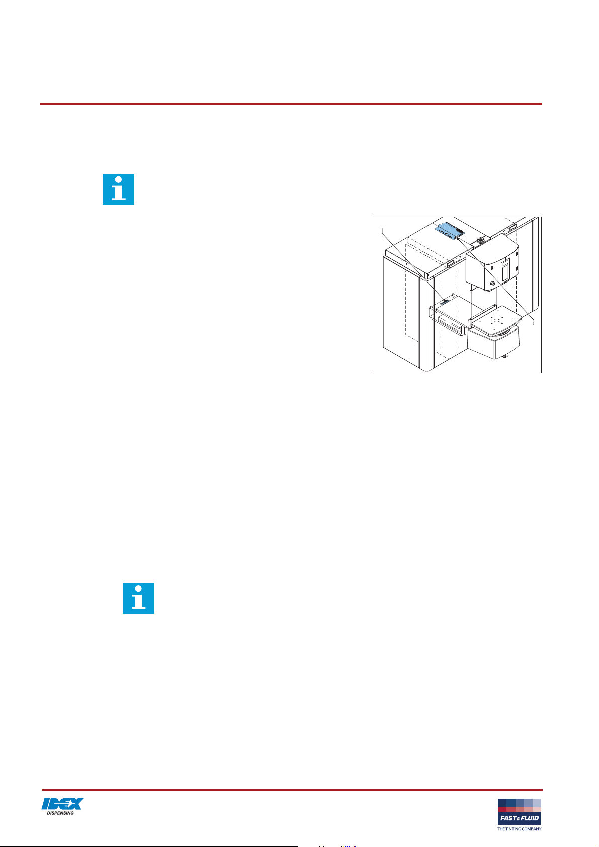
4.3.2 Install the computer
Note
Usually, the computer already has the correct software and drivers installed. If not, refer to the
instructions in the installation manuals of your software provider.
1. Connect the power cables of the computer and the screen to
the 4-way socket (A).
2. Connect an USB cable between the computer and the power
board (B).
3. Connect the keyboard, the mouse and the screen to the
computer.
4.4 Turning on the machine
1. Connect the power cable to the wall socket. When the
machine is operational, you hear two ’beeps’.
2. Make sure that the emergency stop is released.
3. Set the computer switch to ‘ON’.
4.5 First use
1. Fill the brush container. See § 3.3.2.
2. Fill the canisters correctly. See § 3.3.3.
3. Dispense approximately 120 ml colorant into a can. See §
3.2.1.
4. Do step 3 again for all canisters.
A
B
Note
First the air will come out of the nozzle. When
the output is continuous, the tube is filled.
26
Page 27

Troubleshooting HP500 / HP800 V. 3.0
5 Troubleshooting
Note
For all error messages on the computer: see the help topic in the software.
5.1 Contact service
1. Find the type plate on the rear of the machine. See § 3.1.5.
2. Take a note of the model number and the serial number of the
machine.
3. Contact your supplier or manufacturer. See www.fast-
fluid.com.
5.2 Troubleshooting guide
Problem Possible cause Possible solution
Main power supply is
present but the machine
does not work.
Switch plate is not positioned
correctly.
Emergency stop is active. Reset the emergency stop.
A fuse is broken. Contact service. See § 5.1.
Open and close the switch plate. See §
3.3.
27
Page 28

Troubleshooting HP500 / HP800 V. 3.0
28
Page 29
Technical data HP500 / HP800 V. 3.0
6 Technical data
6.1 General specifications
/i
Parameter Specification
HP500 HP800
Model S, M or L XL
Number of canisters 12 to 32 12 to 32
Dispensing 4 Channel Simultaneously 8 Channel Simultaneously
Canister sizes [L] 3, 6, 10 3, 6, 10, 20
Pump type Harbil piston pump Harbil piston pump
Accuracy [mL/step] +/- 0.005 +/- 0.005
Flow rate [L] 0.3 L per minute
0.6 L per minute for the double
pump
0.3 L per minute
0.6 L per minute for the double
pump
Minimum dispensing [mL] 0.05 mL 0.05 mL
Nozzle Rotary nozzle closure (RNC) Rotary nozzle closure (RNC)
Cleaning system Full automatic brush Full automatic brush
Materials used are suitable for Water-, universal- and solvent
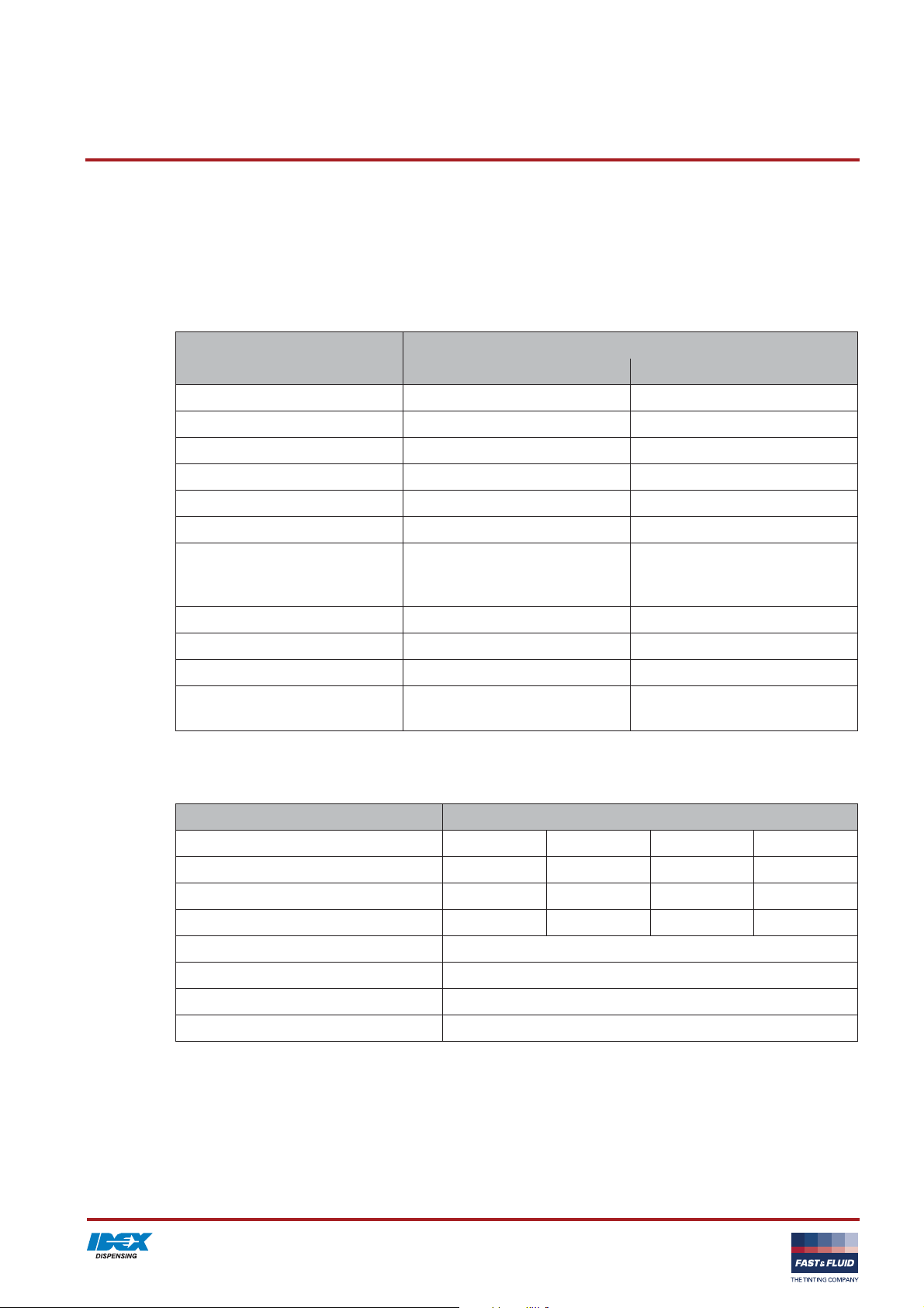
6.2 Dimensions and mass
/i
Parameter Specification
Model S M L XL
Dimensions, height x width x depth [cm] 120x94x94 120x125x94 120x155x94 120x209x94
Net mass [kg] 300 350 400 450
Packed mass [kg] 320 370 420 470
Filling height [cm] 113
Maximum height of the can [cm] 48
Can table dimensions [cm] 44 x 31
Can table loading height [cm] 36
colorants
Water-, universal- and solvent
colorants
29
Page 30

Technical data HP500 / HP800 V. 3.0
6.3 Ambient conditions
/i
Parameter Specification
Temperature [°C] +15 to +40
Altitude above sea level [m], operational -10 to 3000
Altitude above sea level [m], out of operation -10 to 12000
Relative humidity, without condensation [%] 20 to 90
6.4 Noise level
/i
Parameter Specification
Maximum noise level [dB(A)] 70
6.5 Safety classifications
/i
Parameter Specification
IP (Ingress Protection) classification 54
EMC (ElectroMagnetic Compliancy) classification Class B
6.6 Electrical specifications
/i
Parameter Specification
Power consumption, maximum [W] 500 650
Leakage current [mA] 3.5
Fuse specifications [A] T10
Country specific net cables European
HP500 HP800
30
 Loading...