

Page 1
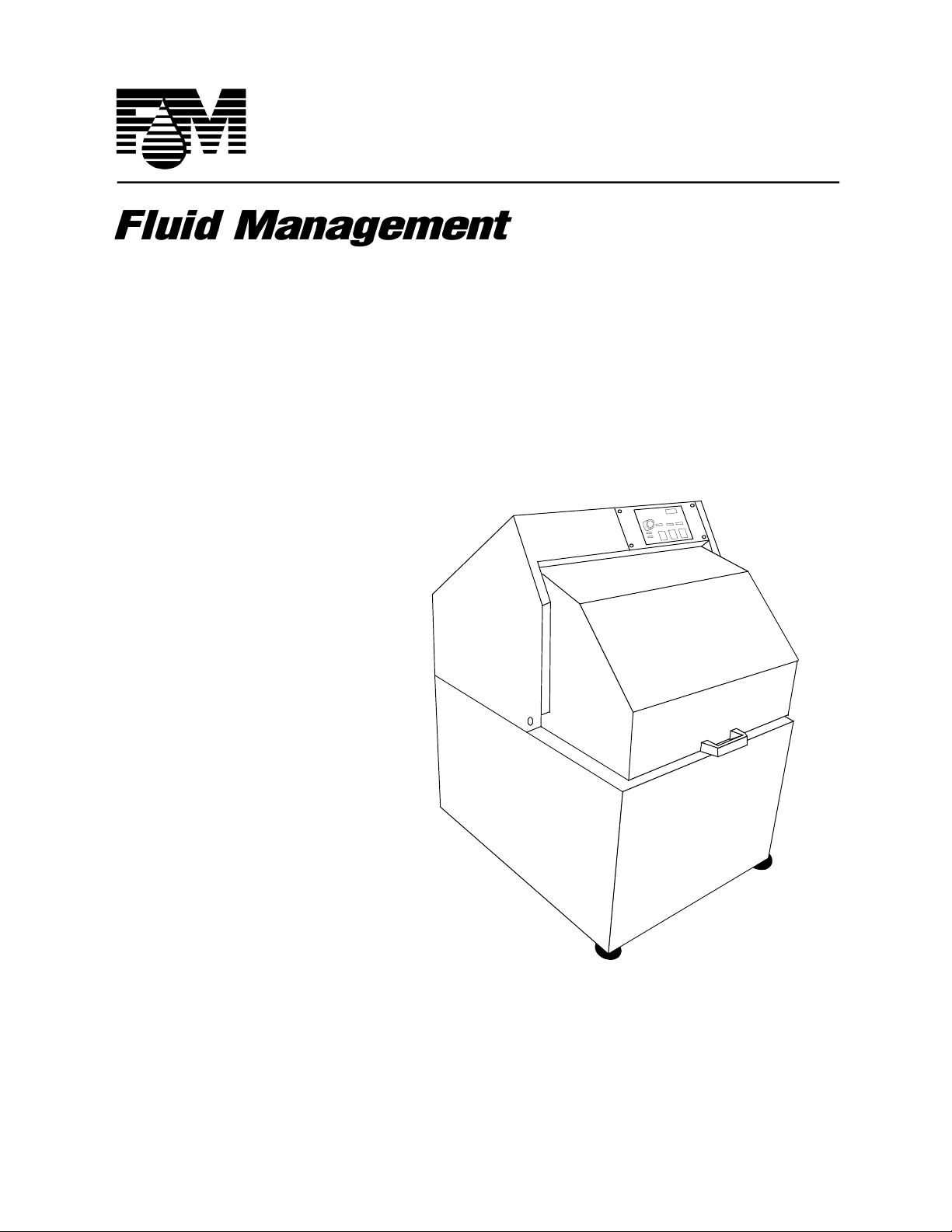
H-5 High Speed
Paint Mixer
®
Operating and
Instruction
Manual
Part # 26019
Rev. C
10/08/01
Page 2

CONFIDENTIAL
PROPERTY OF FLUID MANAGEMENT
(C) COPYRIGHT 2001 FLUID MANAGEMENT
AS AN UNPUBLISHED WORK ALL RIGHTS RESERVED
This material cannot be copied or disclosed to others without
the prior written permission of Fluid Management.
®
FLUID MANAGEMENT
A Unit of IDEX, Corp.
ISO 9001
ISO 14001
1023 Wheeling Road
Wheeling, Illinois 60090-5776
Voice (847) 537-0880
US (800) 462-2466
Fax (847) 537-5530
www.fluidman.com
Page 3

Table Of Cont ents
TABLE OF CONTENTS
SAFETY INFORMATION- - - - - - - - - - - - - - - - - - - - - - - - - - - -5
INTRODUCTION- - - - - - - - - - - - - - - - - - - - - - - - - - - - - - - - - -7
INSTALLATION - - - - - - - - - - - - - - - - - - - - - - - - - - - - - - - - -11
BASIC OPERATION - - - - - - - - - - - - - - - - - - - - - - - - - - - - - -15
MAINTENANCE PROCEDURES - - - - - - - - - - - - - - - - - - - - -17
TROUBLE-SHOOTING CHART - - - - - - - - - - - - - - - - - - - - - -19
SERVICING AND REPAIR - - - - - - - - - - - - - - - - - - - - - - - - - -21
PARTS SECTION- - - - - - - - - - - - - - - - - - - - - - - - - - - - - - - - -28
H-5 Paint Mixer Operating & Instruction Manual 3
Page 4

4 Fluid Management
®
Page 5

SAFETY INFORMATION
SAFETY
INFORMATION
MIXER WARNING LABELS
You should become familiar with important warning labels which are
affixed to the mixer, as well as the symbols which appear throughout this
manual.
Read all warning labels that are on the mixer. Keep them clean so they are
easy to read. If the warning labels become damaged or unreadable, new
labels can be purchased from Fluid Management. See the parts list in the
back of the manual for ordering information.
SAFETY NOTICE INFORMATION
The two main safety notices used in this ma nual are Warning and Caution.
Notices in this manual will look like the example below:
Warning Notice
WARNING: ELECTRICAL HAZARD
Do not operate the mixer with the door
open.Disconnect power before servicing.
A Warning notice tells you about a hazard that could cause serious injury to
you or extensive damage to the mixer. This information is placed at the
beginning of the manual to emphasize the importance of safety to your well
being.
When you see a Warning notice in this manual, read it carefully. Before
continuing with the operation of the mixer, take all necessary precautions to
avoid potential injury.
Caution Notice
CAUTION: ELECTRICAL HAZARD
All electrical components must be kept dry.
Never place containers of liquid on or near
the control box.
H-5 Paint Mixer Operating & Instruction Manual 5
Page 6
SAFETY INFORMATION
A Caution notice tells you about a danger that could cause injury to you or
minor damage to the mixer. When you see a Caution notice in this manual,
read it carefully and be sure you understand it before continuing.
Information Notice
An Information notice gives details that will assist you in efficiently using
the mixer . When you see an Information notice i n this manual, know that it
is there to save you time and energy.
NOTE:
If the cabinet vibrates, loosen the locking
nuts on the right front level ing f oot and
slightly adjust the length.
6 Fluid Management
®
Page 7

INTRODUCTION
INTRODUCTION
The Harbil H-5 High Speed Paint Mixer is a basic, automatic mixer
designed with concern for safety , reli ability and ease of use. It is specifically
designed to be placed on the floor. The gear drive assembly requires no
lubrication. The belt should last for many years with occasional adjustments.
It is a nearly maintenance free device that should deliver many years of
reliable service. Its features include:
• Heavy-duty , high-capacity components and a durable finish for long
wear.
• Vibration-free mixing for blending and conditioning paint.
• Pre-set mixing times with solid state electronic controls and
touchpad.
• Automatic shut off if the door is opened during the mixing operation.
SPECIFICATIONS
Height 40" (101.6 cm.) WITH DOOR OPEN
Width 24-1/8" (61.5 cm.)
Depth 31-1/4" (79.4 cm.)
Weight 310 lbs. (140.6 kg.)
Motor 1/2 HP (Draws 8.4 Amps @ 115 VAC; 4.2 Amps @ 230 VAC)
TYPICAL ELECTRICAL SUPPLY
See name plate for specific information.
115 V ± 10%, 60 Hz 20 Amp
215 V ± 10%, 60 Hz 30 Amp
H-5 Paint Mixer Operating & Instruction Manual 7
Page 8

INTRODUCTION
General Locations
• CONTROL PANEL - All controls are in one location.
• DOOR SAFETY SWITCH -The Door must be closed continuously to
operate the paint mixer.
• WARNING STICKERS - Read these important messages for safety.
• FEET - The feet are factory adjusted to balance the mixer.
CONTROL
PANEL
WARNING
STICKERS
WHEELS
FEET
Figure 1 General Locations
R
O
D
O
Y
T
E
F
A
S
H
C
T
I
W
S
8 Fluid Management
®
Page 9

INTRODUCTION
Control Panel Push-buttons
• POWER ON/OFF pushbutton switch for applying power to the
machine.
• LIGHT membrane pushbutton switch for mixing lighter colors for
short periods of time.
• MEDIUM membrane pushbutton switch for mixing pastels and
moderately tinted colors for normal periods of time.
• DARK membrane pushbutton switch for mixing dark or heavily
tinted colors for longer periods of time.
Control Panel Displays
• NUMERIC DISPLAY for displaying total numbers of mixing cycles
and time remaining to a cycle.
• LIGHT indicator iluminates when mixing short mixing time.
•MEDIUM indicator iluminates when mixing medium mixing time.
• DARK indicator iluminates when mixing long mixing time.
NOTE:
The POWER switch must be ON before the
numeric display shows cycle count or
POWER
ON/OFF
before the
POWER
ON/OFF
H-5 can be operated.
LIGHT
MEDIUM
DARK
DISPLAY
DARK
LIGHT
Figure 2 Control Panel
MEDIUM
H-5 Paint Mixer Operating & Instruction Manual 9
Page 10

INTRODUCTION
Before operating the mixer, carefully read the following important
information.
WARNINGS
• Always shut off the POWER and unplug the mixer from the AC
power outlet before servicing the paint mixer.
• THIS MACHINE IS NOT EXPLOSION-PROOF AND MUST
NOT BE USED IN A FLAMMABLE ATMOSPHERE.
CAUTIONS
• Do not run the paint mixer without a container in place.
• Do not run the paint mixer before removing shipping bolts and
blocks.
10 Fluid Management
®
Page 11
INSTALLATION
INSTALLATION
UNPACKING AND SETUP
INSPECT THE CRATE FOR DAMAGE
IMPORTANT:
If any damage is found, notify the carrier at once
and arrange for inspection in order to claim
recovery. Claims for damage must be made by
the consignee (YOU). The carrier assumes full
responsibility upon acceptance of shipment and
will not entertain any claims by the consignor
(Fluid Management).
REMOVE SHIPPING BLOCKS
1. Look into the open mixer and locate the shipping blocks and bolts.
2. Remove and discard the three (3) bolts that secure the shipping blocks to
the mixer.
3. Remove the bolt that fastens the front of the mixer to the skid.
4. Close the door, release the latches on the back of the mixer and open the
back. (See Figure 7, on page 24)
5. Remove the bolt that fastens the back of the mixer to the skid.
6. Close and latch the back of the mixer.
WARNING:
Do NOT operate the mixer without first
removing the shipping blocks.
BALANCING
The mixer is balanced by the manufacturer at the factory. It is not necessary
to further adjust the feet.
H-5 Paint Mixer Operating & Instruction Manual 11
Page 12

INSTALLATION
CONNECTING TO THE POWER SOURCE
NOTE:
The unit must be plugged into a dedicated
electrical line with no other eq uipment using
the same circuit.
Connect the mixer to a separate, dedicated circuit; for example: 120 volt, 20
ampere. The mixer requires a single, grounded outlet. No other equipment is
to be used on this dedicated line. See “GROUNDING” on page 13.
EXTENSION CORDS
Extension cords for 220 VAC models are not rec ommende d. I f an extension cord is
to be used for 110 VAC models, it should not be combined with other extension
cords. Use only a 3-wire extension cord that has a 3-pole grounding plug. Power
should be provided by a 3-pole receptacle that will accept the plug on the product.
Make sure that your extension cord is in good conditio n. This equ ipment dra ws 5.5
Amps at 115 VAC. An extension cord must be heavy enough to carry the current
your product will draw. An undersized cord can cause a drop in line voltage
resulting in loss of power, overheating and damage to the electronics.
The following chart represents the wire gauge size required in extension
cords for the distance from the grounded receptacle to the equipment.
DISTANCE
GAUGE
SIZE
220V
GAUGE
SIZE
110V
Figure 3 Minimum Wire Gauge for Extension Cords
25 ft50 ft100 ft150 ft200 ft250 ft300 ft400 ft500
ft
18 18 16 14 12 12 10 10 8
18161210108666
12 Fluid Management
®
Page 13

INSTALLATION
GROUNDING
This product should be grounded. In the event of an electrical short circuit,
grounding reduces the risk of electrical shock by causing the over current
protection device to open the electrical circuit. This product is equipped with
a cord having a grounding wire with an appropriate grounding plug. The
plug must be plugged into an outlet that is properly installed and grounded
in accordance with all local codes and ordinances.
DANGER - Improper installation of the grounding plug can result in a risk
of electric shock. If repair or replacement of the cord or plug is necessary, do
not connect the grounding wire to either flat blade terminal. The wire with
insulation having an outer surface that is green with or without yellow
stripes is the grounding wire.
DANGER:
Improper use of the grounding plug can
result in a risk of electric shock.
Check with a qualified electrician or serviceman if the grounding
instructions are not completely understood, or if in doubt as to whether the
product is properly grounded. Do not modify the plug provided. If it will not
fit the outlet, have the proper outlet installed by a qualified electrician.
This product is for use on a nominal 120-volt circuit and has a grounding
plug that looks like the plug illustrated in Figure 4 on page 14. A temporary
adapter that looks like the adapter illustrated in Figure 5 on page 14 may be
used to connect that plug to a 2-pole receptacle as shown, if a properly
grounded outlet is not available. The temporary adapter should be used only
until a properly grounded outlet can be installed by a qualified electrician.
The green colored ridged ear, lug or the like extending from the adapter
must be connected to a permanent ground such as a properly ground outlet
box cover . Whenever the adapter is used, it must be held in place by a metal
screw.
H-5 Paint Mixer Operating & Instruction Manual 13
Page 14

INSTALLATION
PLUG
GROUNDED
OUTLET
WARNING:
After you have plugged the mixer into a
dedicated power line and leveled it, inspect
to be sure that you have removed the
shipping materials inside the mixer.
GROUNDING
PIN
GROUNDED
OUTLET
BOX
Figure 4 Grounded Outlet
MIXER
POWER
CORD
ADAPTER
METAL
SCREW
Figure 5 Adapter Grounding
ADAPTER
TAB FOR
SCREW
GROUNDING
GROUNDED
OUTLET
BOX
Figure 6 Adapter
14 Fluid Management
®
Page 15

BASIC OPERATION
BASIC
OPERATION
1. Open the door.
2. Place a can of paint in the mixer with the bail at the top.
3. Close the door. A safety switch prevents operation of the paint mixer
while the door is open.
4. Apply power to the paint mixer by pressing the POWER switch.
NOTE: When power i s a ppl ied to the mixer, and when it is not in a mixing cycle,
the numeric display will sh ow th e number of cycle s that the uni t has be en
operated.
5. Push one of the three (3) membrane mix pushbutton.
NOTE: The LIGHT membrane pushbutton switch is used for 120 seconds of
mixing time. The MEDIUM
180 seconds of mixing time. The DARK
is used for 240 seconds of mixing time . At this point, the mixer will start
mixing. The appropriate indicator light will illuminate during the mixing
period and the numeric display will start counting down the remaining
time.
membrane pushbutton switch is used for
membrane pushbutton switch
6. After the mixer has stopped, open the door and remove the container of
paint. Power need not be removed if the mixer is in frequent use.
Turn off power at the end of the working period.
H-5 Paint Mixer Operating & Instruction Manual 15
Page 16

BASIC OPERATION
NOTES:
16 Fluid Management
®
Page 17

MAINTENANCE PROCEDURES
MAINTENANCE
PROCEDURES
To ensure safe, dependable operation of the paint mixer, follow the
maintenance schedule detailed below:
AS NEEDED
Cleaning:
• Clean all accessible inside surfaces with soap and water.
• Clean control panel surfaces with soap and water.
• Clean all outside cabinet surfaces with soap and water.
WARNING: ELECTRICAL HAZARD
This mixer is equipped with an automatically
reset thermal limiter to protect the motor
against damage caused by overload
If the motor encounters a mechanical overload condition, a thermal
limiter device will stop the motor. After the device cools, it could
unexpectedly start the motor.
CAUTION: ELECTRICAL HAZARD
All advanced maintenance procedures must
be preformed by an authorized service
representative.
Damage or injury could result if maintenance procedures other than
routine cleaning and belt tension adjustments are preformed by
unauthorized service representatives.
H-5 Paint Mixer Operating & Instruction Manual 17
Page 18

MAINTENANCE PROCEDURES
Use the table below to record your scheduled maintenance on the mixer.
SCHEDULED LUBRICATION & MAINTENANCE RECORD
CYCLES COMPONENT DATE
7500 Belt
BY :
18 Fluid Management
®
Page 19

TROUBLE-SHOOTING CHART
TROUBLESHOOTING
CHART
PROBLEM CHECK ACTION
The paint mixer does not
start.
Using the chart below, locate the problem in the first column, then select the
probable cause to check and action to take from the next two columns. The
problems are arranged from the simplest to the most complex.
Where appropriate, refer to the Servicing and Repair section to correct the
problem.
if mixer attached to power.
receptacle for voltage.
if the front door is not closed.
Motor overload may be tripped. • Allow motor to cool.
May be problem with printed circuit
board.
• Connect to power source.
• Contact electrician.
• Close the front door.
• Call Customer Service.
• Replace printed circuit
board.
Paint mixer will not shut
off.
The shake motor has voltage and hums, but it will
not run.
door limit switch.
timer control board.
if relay is stuck in the closed posi-
tion.
for low line voltage.
belt tension.
belt
motor.
• Replace as required.
• Call Customer Service.
• Replace printed circuit
board.
• Replace if necessary.
• Confirm that the mixer is
on a dedicated line.
• Correct tension.
• Replace as needed.
• Replace motor.
H-5 Paint Mixer Operating & Instruction Manual 19
Page 20

TROUBLE-SHOOTING CHART
An excessive amount of
vibration occurs.
The power is on and nothing happens.
The mixer starts slowly
and then increases to normal speed in a few seconds.
if mixer is out of balance.
if adjustable leg is broken or dam-
aged.
the motor connections.
for broken wire motor cabling.
for faulty contact block on power
switch.
for problem with the motor.
for problem with printed circuit
board.
for problem with POWER switch
belt tension.
• Balance by adjusting the
legs.
• Replace adjustable leg.
• Tighten motor
connections as required.
• Replace motor cable as
needed.
• Replace contact block as
needed.
• Replace motor.
• Call Customer Service.
Replace printed circuit
board.
• Replace as needed.
• Adjust the belt tension.
The mixer speeds up and
slows down.
for the door is making partial con-
tact with the safety switch.
for a damaged wire in motor
cabling.
20 Fluid Management
• Adjust safety switch.
• Replace motor cable.
®
Page 21

SERVICING AND REPAIR
SERVICING
AND REPAIR
GENERAL INFORMATION
If you do not feel confident about disassembling the paint mixer or replacing
a part, DO NOT ATTEMPT THE PROCEDURE. Should problems or
questions arise, contact Customer Service at Fluid Management.
Carefully read all of the instructions before you begin. For component
identification and location, refer to the Parts Section of this manual.
SAFETY PROCEDURE
Warning
WARNING: ELECTRICAL HAZARD
Always shut off the POWER switch and
unplug the mixer before servicing.
Caution
CAUTION:
Wear your safety glasses to prevent
possible injury.
H-5 Paint Mixer Operating & Instruction Manual 21
Page 22

SERVICING AND REPAIR
CHANGING POWER SWITCH
Read all of the following instructions. If you have any doubt about
performing these procedures, please contact Customer Service at Fluid
Management. Turn to the Parts Section of this manual for component
identification and location.
1. Unplug the power cord from the electrical outlet.
2. Remove the four (4) screws at the top of the control panel and save for
3. Lift the control panel off of the mixer enough to expose the wiring.
WARNING: ELECTRICAL HAZARD
Always shut off the POWER switch and
unplug the mixer before servicing.
later use.
4. Unplug the wire Harness from the rectangular 6-pin connector. This will
free the control panel from the mixer.
5. Remove the control panel and place to the side.
6. Remove the replacement switch assembly from the shipping container.
7. Unplug the two (2) brown wires from the terminals labeled 3 and 4 on
the defective switch assembly.
8. Plug the same two (2) brown wires into the terminals labeled 3 and 4 on
the replacement switch assembly.
9. Unplug the brown and blue wires from the terminals labeled (X1) and
(X2) on the defective switch assembly.
10. Plug the same two (2) blue and brown wires into the terminals labeled
X1 and X2 on the replacement switch assembly. (The blue wire must be
terminated on the X2 terminal.
11. Remove the defective switch assembly and discard.
12. Mount the replacement switch assembly in the panel.
13. Re-connect the rectangular 6-pin connector and place the control panel
back on the front of the mixer.
14. Fasten the control panel with the four (4) screws.
22 Fluid Management
®
Page 23

SERVICING AND REPAIR
CHANGING MOTOR
Read all of the following instructions. If you have any doubt about
performing these procedures, please contact Customer Service at Fluid
Management. Turn to the Parts Section of this manual for component
identification and location.
WARNING: ELECTRICAL HAZARD
The mixer must be unplugged before
attempting this procedure. There is a
chance of electrical shock.
1. Unplug the power cord from the electrical outlet.
2. Close front cover of the machine.
3. Release the two (2) latches as shown and open rear of machine.
4. The belt tension is adjustable with an adjustment bolt and locking nut.
To remove belt back off the locking nut and adjust with adjustment bolt
as shown in “Belt Adjustment” on page 25.
5. Remove belt and save as required.
6. Remove the plate covering the motor saving mounting screws for reassembly.
7. Remove cover plate from motor and sketch the wire connections.
8. Remove the three (3) conductors of the power cable that leads to the
device.
9. The motor is foot-mounted. Remove mounting bolts and motor.
10. Using the same mounting hardware, mount the replacement motor.
11. Refer to the sketch, terminate the three (3) motor conductors of the
power cable that leads to the device.
12. Place the plate covering the motor as it was earlier.
13. Install belt as shown in “Belt Adjustment” on page 25.
14. Tension is properly adjusted when approximately four (4) lbs. of force
deflects belt 1/4".
15. Close back cover of machine and secure with latches.
16. Plug machine into power source and test as required.
H-5 Paint Mixer Operating & Instruction Manual 23
Page 24

SERVICING AND REPAIR
CHANGING OR ADJUSTING POLY-V BELT
Read all of the following instructions. If you have any doubt about
performing these procedures, please contact Customer Service at Fluid
Management. Refer to the Parts Section for component identification and
location.
1. Unplug the power cord from the electrical outlet.
2. Close front cover of the machine.
3. Release the two (2) latches as shown and open rear of machine.
OPEN
LATCHES
Figure 7 Opening Rear of Machine
OPEN
4. The belt tension is adjustable with an adjustment bolt and locking nut.
T o loosen or tighten the tension, back off the locking nut and adjust with
adjustment bolt as shown.
5. To replace the belt, back off the locking nut and loosen with adjustment
bolt as shown. Remove belt and install replacement as required.
24 Fluid Management
®
Page 25

SERVICING AND REPAIR
MOTOR
IDLER
PULLEY
IDLER
ADJUSTMENT
BOLT
LOCK
NUT
MAIN
DRIVE
PULLEY
DRIVE
BELT
Figure 8 Belt Adjustment
6. Tension is properly adjusted when approximately four (4) lbs. of force
deflects belt 1/4".
7. Close back cover of machine and secure with latches.
8. Plug machine into power source and test as required.
H-5 Paint Mixer Operating & Instruction Manual 25
Page 26

SERVICING AND REPAIR
CHANGING CONTROL PANEL
Read all of the following instructions. If you have any doubt about
performing these procedures, please contact Customer Service at Fluid
Management.
Turn to the Parts Section for component identification and location.
1. Unplug the power cord from the electrical outlet.
2. Remove the four (4) screws at the top of the control panel and save for
WARNING: ELECTRICAL HAZARD
The mixer must be unplugged before
attempting this procedure. There is a
chance of electrical shock.
later use.
3. Lift the control panel off of the mixer enough to expose the wiring.
4. Unplug the wire Harness from the rectangular 6-pin connector. This will
free the control panel from the mixer.
5. Remove the control panel and discard.
6. Install the replacement part
7. Re-connect the rectangular 6-pin connector and place the control panel
back on the front of the mixer.
8. Fasten the control panel with the four (4) screws.
26 Fluid Management
®
Page 27

SERVICING AND REPAIR
NOTES:
H-5 Paint Mixer Operating & Instruction Manual 27
Page 28

PARTS SECTION
PARTS
SECTION
This section is designed to assist you in
• Performing service functions
and
• Identifying parts.
All repairs must be performed by qualified service personnel.
TERMS: Unless prior arrangements have been made, parts will be shipped UPSCOD. All prices are F.O.B. Wheeling, Illinois, and are subject to change without
notice.
In all correspondence or phone orders for parts, please state model number and
serial number of the equipment.
RETURNS: No parts are to be returned without prior authorization. A Returned
Goods Authorization number is required.
28 Fluid Management
®
Page 29

EQUIPMENT MAINTENANCE LOG
RECORD MODEL NUMBER HERE: _________________________
RECORD SERIAL NUMBER HERE: _________________________
SERVICE
DATE
DESCRIPTION & PARTS REPLACED
(STATE IF UNDER WARRANTY)
SERVICED
BY
H-5 Paint Mixer Operating & Instruction Manual 29
Page 30

PARTS SECTION
SERVICE
DATE
DESCRIPTION & PARTS REPLACED
(STATE IF UNDER WARRANTY)
SERVICED
BY
30 Fluid Management
®
Page 31

SPARE PARTS ORDER
Fluid Management Parts Order Form
Photocopy and use this form to
Mail or Fax orders to:
Fluid ManagementA unit of IDEX | Phone: 1(800) 462-2466
1023 South Wheeling Road | Fax: 1(847) 537-5530
Wheeling, IL 60090 |
|
Sold To: Ship To:
_____________ __ _________ _________ __ ___ __________
_____________ __ _________ _________ __ ___ __________
_____________ __ _________ _________ __ ___ __________
_____________ __ _________ _________ __ ___ __________
P.O. Number___________
PHONE # (___)___-____
Ship Via: ______________________ Collect Prepaid
Taxable Tax Exem p t (Fax copy of exemption certificate.)
QUANTITY PART
NUMBER
Comments: ____________________________________________________
DESCRIPTION UNIT
____________________________________________________
____________________________________________________
_______________________ ________________________
Name
(Please print) Signature
PRICE
______________
Date:
H-5 Paint Mixer Operating & Instruction Manual 31
Page 32

PARTS SECTION
PANEL
25852
SWITCH
25423
OVERLAY
24398
SCREW
4000093
LIMIT
SWITCH
03179
NUT
4000094
CONTROL
ASSY
24429
LOCK
WASHER
02962
WASHER
4000110
SWITCH
BLOCK
25425
LATCH
25424
HARNESS
25970
RELAY
5608204
Figure 9 Control Panel 25967
32 Fluid Management
®
Page 33

PART NO DESCRIPTION NO REQ
02962 # 6 LOCK WASHER 2
24129 CONTROL ASSEMBLY WITH 3-SWITCH PCB 1
24398 OVERLAY 1
25423 POWER SWITCH OPERAT OR 1
25424 SWITCH MOUNTING LATCH 1
25425 SWITCH MOUNTING BLOCK 1
25852 CONTROL PANEL 1
25967 CONTROL ASSEMBLY COMPLETE 1
25970 WIRE HARNESS 1
4000110 # 6 FLAT WASHER 2
5608204 RELAY 1
40000093 6-32 SCREW 10
40000094 6-32 NUT 2
H-5 Paint Mixer Operating & Instruction Manual 33
Page 34

PARTS SECTION
COUNTER
WEIGHT
16120
SCREW
F0104A4B44
ARM
16096
PULLEY
16008
GEAR
25789
SCREW
F0104A5B36
SCREW
F0103816
SHAFT
25929
PIN
F0115A0816
SHAFT
& HUB
16022
GEAR
25788
SHOULDER
SCREW
F01130424
NUT
F01137
LOCK
WASHER
16107
NUT
16106
BEARING
16105
PIN
F0108A09N16
OPTIONAL
SQUARE
CAN
HOLDER
25723
CAN
HOLDER
25936
Figure 10 Transmission Arm Assembly
34 Fluid Management
®
Page 35

PART NO DESCRIPTION NO REQ
16008 DRIVE PULLEY 1
16022 SECONDARY SHAFT & HUB 1
16032 POLY-V BELT (NOT SHOWN) 1
16080 1/2 HP, 115/230 VAC MOTOR (NOT SHOWN) 1
16096 TRANSMISSION ARM (INCLUDES BEARINGS) 1
16105 BEARING 2
16106 NUT 1
16107 LOCK WASHER 1
16120 COUNTER WEIGHT 1
25723 SQUARE CAN HOLDER (OPTION FOR MIXING SQUARE CANS) 1
25788 32 TOOTH BEVEL GEAR 1
25789 64 TOOTH BEVEL GEAR 1
25935 TRANSMITION ARM ASSEMBLY COMPLETE 1
25936 STANDARD CAN HOLDER 1
F0103816 1/2” - 13 X 1 SCREW 1
F0104A4B44 1/4-20 X 2-1/4 SCREW 2
F0104A5B36 5/16-18 2-1/4 SCREW 4
F0108A09N16 1/4 ROLL PIN 2
F01 130424 SHOULDER SCREW 1
F0115A0816 5/16 DOWEL PIN 2
26056 ONE GALLON ADAPTER (NOT SHOWN)
(OPTION FOR MIXING ONE-GALLON CANS)
F01173 NUT W/ LOCK WASHER 1
N/A
H-5 Paint Mixer Operating & Instruction Manual 35
Page 36

Part No. 26019
Rev. C
10/08/01
Fluid Management
1023 Wheeling Road
Wheeling, Illinois 60090-5773
Telephone: (847) 537-0880
1-800-462-2466
Fax (847) 537-5530
www.fluidman.com
Part No. 26019
Rev. C
10/08/01
 Loading...