

Page 1
Manual GA450
V. 2.2
Fast & Fluid Management B. V.
PO Box 220
2170 AE Sassenheim
The Netherlands
www.fast-fluid.com
Page 2

© Fast & Fluid Management B.V.
This manual or parts thereof may not be reproduced, stored in a retrieval system, or transmitted, in any form or by any means,
electronic, mechanical, photocopying, recording, nor otherwise, without the prior written permission of Fast & Fluid
Management B.V.
This manual could contain technical inaccuracies or typographical errors.
Fast & Fluid Management B.V. reserves the right to revise this manual from time to time in the contents thereof without the
obligation of Fast & Fluid Management B.V. to notify any person of such revision or change.
Details and values given in this manual are average values and have been compiled with care. They are not binding, however,
and Fast & Fluid Management B.V. disclaims any liability for damage or detriments suffered as a result of reliance on the
information given herein or the use of products, processes or equipment to which this manual refers. No warranty is made that
the use of the information or of the products, processes or equipment to which this manual refers will not infridge any third
party’s patents or rights. The information given does not release the user from making their own experiments and tests.
2
Page 3

Table of Contents
Table of Contents
1 About this manual.........................................................................................................5
1.1 How to work with the manual .......................................................................................... 5
1.2 Record of changes ......................................................................................................... 5
2 Safety ............................................................................................................................. 7
2.1 Intended use ................................................................................................................... 7
2.2 Liability ............................................................................................................................ 7
2.3 User qualification for installation ..................................................................................... 7
2.4 CE certification ............................................................................................................... 7
2.5 Safety symbols on the machine ...................................................................................... 8
2.6 Labels on the machine ................................................................................................... 8
2.7 Safety symbols in the manual ......................................................................................... 8
2.8 Disposal of the machine ................................................................................................. 9
3 Operator manual .........................................................................................................11
3.1 Description .................................................................................................................... 11
3.1.1 Overview of the machine.................................................................................... 11
3.1.2 Overview of the control panel............................................................................. 12
3.1.3 Type plate: serial number................................................................................... 12
3.1.4 Type plate: details ..............................................................................................12
3.2 Operation ...................................................................................................................... 13
3.2.1 Turning on the machine...................................................................................... 13
3.2.2 Turning on the machine when the machine is in hybernation ............................ 13
3.2.3 Normal mix procedure ........................................................................................ 13
3.2.4 Placing the can................................................................................................... 13
3.2.5 Start the machine ...............................................................................................15
3.2.6 Remove the can .................................................................................................15
3.2.7 Stop the operation manually............................................................................... 16
3.2.8 Adjust the mix speed .......................................................................................... 16
3.2.9 Adjust the mix time ............................................................................................. 17
3.3 General cleaning: after every operation ....................................................................... 18
3.4 Periodic maintenance: weekly ...................................................................................... 18
3.5 Periodic maintenance: monthly .................................................................................... 18
3.6 Remove spilled paint .................................................................................................... 19
3
Page 4

Table of Contents
4 Installation ...................................................................................................................21
4.1 Unpack the machine ..................................................................................................... 21
4.1.1 Remove the cardboard....................................................................................... 21
4.1.2 Remove the plastic protection and foil ...............................................................21
4.1.3 Remove the transport brackets .......................................................................... 22
4.1.4 Dispose of the packaging material ..................................................................... 22
4.2 Put the machine in position .......................................................................................... 22
4.2.1 Move the machine from the pallet ...................................................................... 22
4.2.2 Move the machine to the final location ............................................................... 23
4.2.3 Level the machine ..............................................................................................23
4.3 Finish the installation .................................................................................................... 23
5 Troubleshooting.......................................................................................................... 25
5.1 General troubleshooting procedure .............................................................................. 25
5.2 Contact service ............................................................................................................. 25
5.3 Troubleshooting guide .................................................................................................. 26
5.3.1 Easy-to-solve errors ...........................................................................................26
5.3.2 Clamp plate errors.............................................................................................. 26
5.3.3 Inverter errors..................................................................................................... 26
5.3.4 Software errors................................................................................................... 27
5.4 Reset after an emergency stop .................................................................................... 27
5.5 Start again after a power failure ................................................................................... 27
5.6 Restart the machine ..................................................................................................... 27
6 Technical data .............................................................................................................29
6.1 General specifications .................................................................................................. 29
6.2 Dimensions and mass .................................................................................................. 29
6.3 Ambient conditions ....................................................................................................... 29
6.4 Noise level .................................................................................................................... 29
6.5 Safety classifications .................................................................................................... 30
6.6 Electrical specifications ................................................................................................ 30
6.7 Electrical diagram ......................................................................................................... 31
4
Page 5

About this manual GA450 V. 2.2
1 About this manual
The manual shows the information necessary to:
-install
- operate
- perform basic maintenance
- correct small problems
The GA450 and all its versions are referred to in the manual as the ’machine’.
This manual contains the original instructions. The original language of the manual is English.
1.1 How to work with the manual
1. Familiarize yourself with the structure and content.
2. Read the safety chapter in detail and make sure you understand all the instructions. See § 2.
3. Carry out the actions completely and in the given sequence.
1.2 Record of changes
/i
Edition Editor Check Date Description
1.0 TB MV 07/2010 First edition
2.0 ET TB 09/2012 Updated edition
2.2 ET TB 07/2013 Updated edition
5
Page 6

About this manual GA450 V. 2.2
6
Page 7

Safety GA450 V. 2.2
2 Safety
WARNING
Read the manual before you install or use the machine. Failure to do so can
result in personal injury, death or property damage.
2.1 Intended use
The machine is designed to mix paint in a can. Any other use of the machine is strictly forbidden.
2.2 Liability
Our machines and accessories are fully compliant with the CE regulations. Any modification can result in not
fulfilling the CE safety requirements and is therefore not allowed. Fast & Fluid Management B.V. will not accept
any responsibility in case of modifications to machines and/or accessories.
Fast & Fluid Management B.V. is not liable if you do not follow the rules below:
- Do not use a damaged machine. When you have doubts, contact your supplier. See § 5.1.
- The machine is for indoors use only.
- Install and connect the machine according to the instructions in this manual.
- Observe all local safety regulations.
- Connect the machine to a grounded wall socket.
- Keep the machine in good condition. Make sure that defective parts are immediately replaced.
- This machine may only be used for commercial settings. The machine is not a household appliance.
- Make sure that the machine is installed as prescribed in this manual
- Replace parts only with original Fast & Fluid Management B.V. spare parts.
All maintenance beyond the scope of this manual must be carried out by a qualified service technician that Fast
& Fluid Management B.V. has trained and certified.
2.3 User qualification for installation
Only install the machine if you have written permission from the supplier of the machine.
2.4 CE certification
The machine is CE certified. This means that the machine complies with the essential requirements concerning
safety. The directives that have been taken into consideration in the design are available on www.fast-fluid.com
.
7
Page 8
Safety GA450 V. 2.2
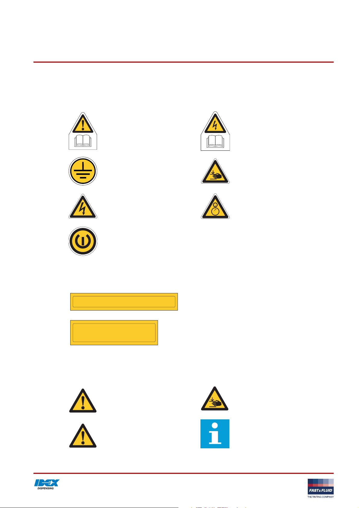
2.5 Safety symbols on the machine
/i
Read the manual. Electrical hazard. Read the manual.
Central earthing point. Pinch hazard.
Electrical hazard. Rotating parts.
On-Off
2.6 Labels on the machine
/i
When can diameter > Ø39 cm : remove shield
When can diameter > Ø40,2 cm and
height <28 cm : use adapters
2.7 Safety symbols in the manual
/i
WARNING
Can cause personal injury.
Upper and lower shield instruction.
WARNING
Pinch hazard.
CAUTION
Can cause damage to the machine.
Note
Shows further information.
8
Page 9

Safety GA450 V. 2.2
2.8 Disposal of the machine
1. Sort the machine, the accessories and the packaging for
environmentally friendly recycling.
2. Do not dispose of the machine into domestic waste. Dispose
of the machine according to local regulations.
9
Page 10

Safety GA450 V. 2.2
10
Page 11

Operator manual GA450 V. 2.2
3 Operator manual
3.1 Description
3.1.1 Overview of the machine
L M
K
B
A
J
I
C
D
H
G
E
F
A: Door
B: Casing
C: Control panel. See also § 3.1.2.
D: Emergency stop
E: Wheel
F: Adjustable foot
G: Can plate (bottom)
H: Can table
I: Drain orifice
J: Can plate (top)
K: Type plate. See also § 3.1.4.
L: Net entry
M: Main switch
11
Page 12

Operator manual GA450 V. 2.2
3.1.2 Overview of the control panel
A: Stop/Up key
B: Program key
C: T1 key (Time 1)
D: T2 key (Time 2)
E: T3 key (Time 3)
F: S-key (mix speed)
G: Display
Note
The function of the T1 to T3 keys changes when you
adjust the default values of the machine. See also §
3.2.8 and § 3.2.9.
3.1.3 Type plate: serial number
Fast & Fluid Management B.V.
IDEX Dispensing
&
FAST FLUID
THE TINTING COMPANY
P.O. Box 220
2170 AE Sassenheim
The Netherlands
Model
XXXXX-XXX
Prod. Week XX-XXXX
Serial No.
B G A
r d y
C D E F
XXXXX-XX-XXXXXX
3.1.4 Type plate: details
&
FAST FLUID
THE TINTING COMPANY
XXX
V XX Hz
Model XXXXX-XXX
Serial no. XXXXX-XX-XXXXXX
Prod. week XX-XXXX
Mass XXX XX
Fuse XX XX
Design
XXX
W
c
Fast & Fluid Management B.V.
IDEX Dispensing
P.O. Box 220
2170 AE Sassenheim
The Netherlands
Made in XXXXXXXXX
12
Page 13

Operator manual GA450 V. 2.2
3.2 Operation
WARNING
Only push the emergency stop in the case of a safety emergency.
3.2.1 Turning on the machine
1. Connect the power cable to the grouned wall socket.
2. Make sure that the emergency stop is released.
3. Set the Main switch to ‘ON’. When the machine is on, you
hear two ‘beeps’ and the display shows ‘...’.
4. Press the Stop/Up key. When the machine is operational, the
display shows ‘rdY’.
3.2.2 Turning on the machine when the machine is in hybernation
When the machine is in hybernation, the display shows ‘.’
1. Press the Stop/Up key. When the machine is operational, the
display shows ‘rdY’.
3.2.3 Normal mix procedure
1. Place the can. See § 3.2.4.
2. Adjust the default mix speed and time, if necessary. See §
3.2.8 and § 3.2.9.
3. Start the machine, See § 3.2.5.
4. Remove the can. See § 3.2.7.
3.2.4 Placing the can
Pull out the can table
1. Open the door.
2. Pull up the handle (A) to unlock the can table (B).
3. Pull out the can table until you hear a ‘click’. The can table is
locked.
B
13
2
1
A
Page 14

Operator manual GA450 V. 2.2
Place the can
1. Put one or more cans (A) in the centre of the can table, or in
a pattern that has its gravitational centre in the middle of the
can table.
WARNING
It is possible that the can is heavy. Use the
correct lifting tool when appropriate. Obey the
local regulations.
CAUTION
Make sure that all cans have the same height.
Do not stack cans upon each other.
Note
When the diameter of the can is > Ø39 cm,
remove the upper shield.
12
34
A A
A A
A
A
Note
When the diameter of the can is > Ø40.2 cm
and the height < 28 cm, use adapters.
2. If the can plates are too close to each other, press the Stop/
Up key until you can place the can.
3. If you mix more than one can at the same time, make sure
that the can handles can not move. Use self-adhesive tape,
for example.
If you mix one can:
1. Retain the can handle with the provided elastic band.
B
A
14
Page 15

Operator manual GA450 V. 2.2
Close the door
1. Pull up the handle (A) to unlock the can table.
2. Push the can table (B) inwards until you hear a ‘click’. The can
table is locked.
3. Close the door.
B
2
1
A
3.2.5 Start the machine
1. Push the T1, T2 or T3 key and select the mix time. See the
table below. The machine automatically clamps the can and
operates for the chosen time. See § 3.2.8.
2. When the machine detects no can, the machine does not start
to mix. In this case, stop the operation manually. See § 3.2.7.
3.2.6 Remove the can
1. Open the door.
2. Pull up the handle (A) to unlock the can table (B).
3. Pull out the can table until you hear a ‘click’. The can table is
locked.
4. Remove the elastic band.
Note
The display shows the time in seconds that
remain before you can open the door.
Note
While the machine operates, you can adjust
the mix time with the + and - keys.
15
B
2
1
A
Page 16

Operator manual GA450 V. 2.2
3.2.7 Stop the operation manually
1. Push the Stop/Up key.
2. Wait until the can plates are open.
3. If necessary, remove the can. See § 3.2.6.
3.2.8 Adjust the mix speed
Note
The machine controls the mix speed based on the
size of the can. For some cans it might be
necessary to adjust the mix speed. Contact you
paint supplier.
Note
You can adjust the mix speed when the display
shows ‘rdY’.
1. Push the S-key. The display shows the last-chosen speed.
This is the default mix speed.
2. Push the S-key a number of times to select SP1, SP2, SP3 or
SP4. SP1 is the lowest mix speed, SP4 is the highest mix
speed.
Note
If the mix speed that you selected differs from the
standard speed, the machine will remember the
setting until a can of another size is placed on the
can table.
Note
If the mix speed that you selected is too high for the
can height, the machine automatically sets the
speed to SP1, SP2 or SP4 according to the can
height. Refer to the figure below.
16
Page 17

Operator manual GA450 V. 2.2
250
SP4
SP3
200
150
SP2
SP1
100
50
A (rpm)
A: Speed (rpm)
B: Can height (cm)
0
Switch point 3
Switch point 2
10 20 30 40 50
B (cm)
Switch point 1
Note
The mix speed depends on the can height.
3.2.9 Adjust the mix time
/i
Key pushed Mix time [s]
T1 60
T2 120
T3 180
T1 + T2 at the same time 60 + 120 = 180
T1 + T3 at the same time 60 + 180 = 240
T2 + T3 at the same time 120 + 180 = 300
17
Page 18

Operator manual GA450 V. 2.2
Note
The table shows the default values.
Note
You can adjust the default mix time when the
display shows ‘rdY’.
1. At the same time, push the Program key and the T1, 2 or 3
key.
2. Push the + or - key to adjust the mix time for T1, 2 or 3.
3. To save the new mix time, push the S-key.
4. If you do not want to save the new mix time, push the Stop/Up
key.
3.3 General cleaning: after every operation
1. Clean the machine with a cloth and remove all spilled paint or
other liquid.
CAUTION
Do not use cleaning agents based on organic
solvents to clean painted or plastic parts of the
machine.
3.4 Periodic maintenance: weekly
1. Remove the paint. Refer to § 3.6.
CAUTION
Do not use cleaning agents based on organic
solvents to clean painted or plastic parts of the
machine.
2. Grease the spindles.
3.5 Periodic maintenance: monthly
1. Remove paint and dirty grease. Add new grease.
CAUTION
Do not use cleaning agents based on organic
solvents to clean painted or plastic parts of the
machine.
2. Grease the axle and other sliding parts.
18
Page 19

Operator manual GA450 V. 2.2
3.6 Remove spilled paint
Do this procedure when paint is spilled inside the machine.
1. Make sure that the machine is stopped. See § 3.2.5 or § 3.2.7.
2. Put a reservoir (A) below the drain orifice (B).
CAUTION
Make sure that the reservoir is big enough to
hold all the spilled paint.
3. Remove the cap (C) from the drain orifice. The spilled paint
comes out of the machine.
4. Dispose of the spilled paint according to local regulations.
5. Install the cap to the drain orifice.
6. Clean the machine. See § 3.3.
B
C
B
A
19
Page 20

Operator manual GA450 V. 2.2
20
Page 21

Installation GA450 V. 2.2
4 Installation
4.1 Unpack the machine
4.1.1 Remove the cardboard
1. Remove the tensioning straps (A).
2. Remove the cardboard (B).
A
FAST FLUID
B
&
4.1.2 Remove the plastic protection and foil
1. Remove the plastic protection (A).
2. Remove the plastic foil (B).
A
B
21
Page 22

Installation GA450 V. 2.2
4.1.3 Remove the transport brackets
1. Remove the screws (A).
2. Remove the transport brackets (B).
B
12mm
A
4x
4.1.4 Dispose of the packaging material
1. Dispose of the packaging material in an environmentally
friendly way, according to local regulations.
4.2 Put the machine in position
4.2.1 Move the machine from the pallet
1. Place the optional ramp (A).
2. Push the machine from the pallet on to the ground.
CAUTION
Do not use a fork-lift truck.
A
22
Page 23

Installation GA450 V. 2.2
4.2.2 Move the machine to the final location
1. Push the machine to the final location.
CAUTION
Do not use a fork-lift truck.
Note
Make sure the final location is sufficiently
illuminated.
2. Connect the power cable to the net entry.
3. Connect the power cable to the wall socket.
4.2.3 Level the machine
1. Move down the adjustable feet (B) until the wheels (A) are off
the ground.
2. Adjust the height of the feet and make sure that the machine
is leveled.
3. Tighten the nuts (C) to lock the feet.
4.3 Finish the installation
1. Turn on the machine. See § 3.2.1.
C
D
AB
17mm
23
Page 24

Installation GA450 V. 2.2
24
Page 25

Troubleshooting GA450 V. 2.2
5 Troubleshooting
5.1 General troubleshooting procedure
1. Try to solve the problem with the information in this manual.
See § 5.3.1.
2. If it is not possible to solve the problem with the information in
this manual, contact service. See § 5.2.
5.2 Contact service
1. Find the type plate on the rear of the machine. See § 3.1.4.
2. Take a note of the model number and the serial number of the
machine.
3. Contact your supplier or manufacturer.
See www.fast-fluid.com
.
25
Page 26

Troubleshooting GA450 V. 2.2
5.3 Troubleshooting guide
5.3.1 Easy-to-solve errors
Problem Possible cause Possible solution
The display shows ‘E00’ Emergency stop is pressed during
idle state.
The display shows ‘E01’ The door is open. Close the door.
The display shows ‘E05’ The cradle lock failed to release
the cradle.
The display shows ‘E08’ Emergency stop is pressed during
running state.
Release the emergency stop. See § 5.4.
Reset the machine. See § 5.4.
When the problem persists, contact
service. See § 5.2.
Release the emergency stop. See § 5.4.
The display shows ‘E11’ No can found during clamping or
5.3.2 Clamp plate errors
Problem Possible cause Possible solution
The display shows ‘E40’ Home sensor not found. Reset the machine. See § 5.4.
The display shows ‘E41’ Top of clamp plates is not reached
The display shows ‘E42’ Clamp plate is sticking on can.
The display shows ‘E43’ Clamp plate is stuck in up position.
5.3.3 Inverter errors
Problem Possible cause Possible solution
The display shows ‘E50’ Inverter is in error mode. Reset the machine. See § 5.4.
The display shows ‘E51’ Failed to initialize inverter. Reset the machine. See § 5.4.
can is too small.
in time.
Cradle lock is stuck.
Cradle lock is stuck.
Install a can. See § 3.2.4.
When the problem persists, contact
service. See § 5.2.
Reset the machine. See § 5.4.
When the problem persists, contact
service. See § 5.2.
Reset the machine. See § 5.4.
When the problem persists, contact
service. See § 5.2.
Reset the machine. See § 5.4.
When the problem persists, contact
service. See § 5.2.
When the problem persists, contact
service. See § 5.2.
When the problem persists, contact
service. See § 5.2.
The display shows ‘E54’ Failed to run the mixer motor
forward.
26
Reset the machine. See § 5.4.
When the problem persists, contact
service. See § 5.2.
Page 27

Troubleshooting GA450 V. 2.2
Problem Possible cause Possible solution
The display shows ‘E55’ Failed to run the mixer motor
The display shows ‘E56’ Failed to stop the mixer motor. Reset the machine. See § 5.4.
The display shows ‘E57’ Failed to brake the mixer motor. Reset the machine. See § 5.4.
The display shows ‘E58’ Failed to stop braking the mixer
The display shows ‘E60’ Failed to send parameter to
The display shows ‘E61’ Failed to send home command to
5.3.4 Software errors
Problem Possible cause Possible solution
The display shows ‘F00’ Parameter is not available. Contact service. See § 5.2.
backward.
motor.
inverter.
inverter.
Reset the machine. See § 5.4.
When the problem persists, contact
service. See § 5.2.
When the problem persists, contact
service. See § 5.2.
When the problem persists, contact
service. See § 5.2.
Reset the machine. See § 5.4.
When the problem persists, contact
service. See § 5.2.
Reset the machine. See § 5.4.
When the problem persists, contact
service. See § 5.2.
Reset the machine. See § 5.4.
When the problem persists, contact
service. See § 5.2.
The display shows ‘F54’ Invalid state value. Contact service. See § 5.2.
5.4 Reset after an emergency stop
WARNING
Make sure that the problem is solved before you
reset the emergency stop.
1. Unlock the emergency stop.
2. Push the Stop/Up key. When the machine is operational, the
display shows ‘rdY’.
5.5 Start again after a power failure
1. Press the emergency stop button.
2. Reset the machine. See § 5.4.
5.6 Restart the machine
1. Set the main switch to ‘OFF’.
2. Wait 30 seconds.
3. Turn on the machine. See § 3.2.1.
27
Page 28

Troubleshooting GA450 V. 2.2
28
Page 29

Technical data GA450 V. 2.2
6 Technical data
6.1 General specifications
/i
Parameter Specification
Materials used are suitable for Water-, universal- and solvent colorants
Maximum load weight [kg] 40
Can plate diameter [cm] 38
Can plate bottom seating diameter [cm] 36
Maximum can height [cm] 48
Minimum can height [cm] 7
Mix ratio [horzontal:vertical] 1:2
6.2 Dimensions and mass
/i
Parameter Specification
Main dimensions, height x width x depth [cm] 108x86x75
Detailed dimensions, height x width x depth [cm] 109.8x86.1x75
Packed dimensions, height x width x depth [cm] 126x97x90
Net mass [kg] 210
Packed mass [kg] 247
6.3 Ambient conditions
/i
Parameter Specification
Temperature [°C] +5 to +40
Altitude above sea level [m], operational (Max.) 2000
Altitude above sea level [m], out of operation (Max.) 12000
Relative humidity, without condensation [%] 20 to 90
6.4 Noise level
/i
Parameter Specification
Maximum noise level [dB(A)] <65
29
Page 30

Technical data GA450 V. 2.2
6.5 Safety classifications
/i
Parameter Specification
IP (Ingress Protection) classification 32
EMC (ElectroMagnetic Compliancy) classification Class B
6.6 Electrical specifications
/i
Parameter Specification
Power consumption, maximum [W] 850
Voltage [V] 230 (/115 optional)
Frequency [Hz] 50/60
Speed [rpm] 100 to 230
Fuse specifications [A] T10
Country specific net cables European
30
Page 31

Technical data GA450 V. 2.2
6.7 Electrical diagram
F1
1
2
CABLE 14
EMERGENCY SWITCH
CABLE 14
1816801
BLACK
1816897
CABLE 6
CABLE 3
CABLE 3
1816790
24VDC POWER
CABLE 4
BROWN
MAINSWITCH
BROWN
CABLE 4
1816791
BLUE
BLUE
CABLE 2
FILTER
CABLE 2
1816789
YEL/GRN
YEL/GRN
YEL/GRN
BROWN
BLUE
YEL/GRN
FUSE
CABLE 1
CABLE 1
1816788
CENTRAL EARTH POINT
EARTH FRAME
EARTH INVERTER COVER
EARTH INVERTER HEATSINK
0
Sheet
2.1
Version
First version
Added 2nd doorlock/switch
Changed partnr. cable 6
Added wire colors, added mixer motor cable detail
Version 2.0
Extra cradlemotorswitch, modied ltercables
NvB
NvB
NvB
NvB
NvB
GA450 Mixer Wiring
Date Drawn Remarks
22-9-2011
29-9-20111.2
17-10-20111.3
9-4-20132.0
GA450 Mixer Wiring
Title
FAST & FLUID
4-6-20132.1
Filename
Revnr.
1.0 5-7-2011 NvB
1.1
The Netherlands
2170 AE Sassenheim
PO Box 220
Hub v. Doorneweg 31
© Fast & FLuid
Tuesday, June 04, 2013
1
2
CABLE 5
3
CABLE 5
INVERTER
DISPLAY/KEYBOARD
321
1816792
3
MIXERMOTOR
OPTICAL SENSORS
321
CABLE 9
CABLE 9
1816796
4
CABLE 7
CABLE 7
CABLE 8
CABLE 8
1816795
5
D D
DOORLOCK1
1816794
CONTROL BOARD
DOORLOCK2
BROWN
BLUE
C C
CRADLELOCK
M
CABLE 10
CABLE 10
1816797
BROWN
BLUE
BLUE
BROWN
BLUE
BROWN
CABLE 11
CABLE 11
1816798
B B
DOORSWITCH1
CABLE 13
CABLE 13
1816800
DOORSWITCH2
4
CABLE 12
CABLE 12
1816799
5
CRADLELOCK SWITCH2
A A
CRADLELOCK SWITCH1
31
Page 32

Technical data GA450 V. 2.2
32
 Loading...