

Page 1
FAST & FLUID MANAGEMENT srl
A Unit of Idex Corporation
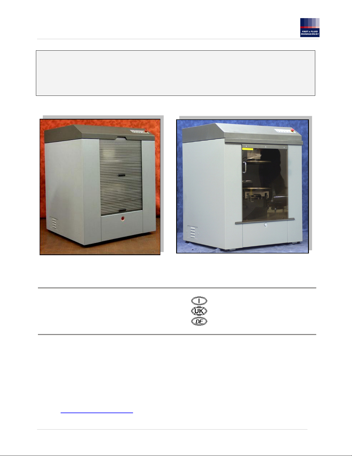
Automatic Mixer Ferraris
FAST & FLUID MANAGEMENT Srl
A Unit of IDEX Corporation
Via Pelizza da Volpedo, n° 109/111
20092 Cinisello Balsamo (MI)
ITALY
Tel. : +39 02 66091.1
Fax : +39 02 66091550
Web : http://www.fast-fluid.com/
MANUALE OPERATIVO
USER MANUAL
BETRIEBSHANDBUCH
1155432A-it,en,de.doc – 11/09/2006
1
Page 2

FAST & FLUID MANAGEMENT srl
A Unit of Idex Corporation
INDICE CONTENTS
Pag.
1. Specifiche tecniche 3 1. Technical specifications 3
2. Condizioni di garanzia 4 2. Terms of warranty 4
3. Introduzione 5 3. Opening statement 22
Dichiarazione dei diritti alla proprietà
4.
intellettuale
5 4. Proprietary notice 22
5. Descrizione generale 5 5. General Description 22
6. Regole per la sicurezza 6 6. Safety specifications 23
7. Rischi residui 7 7. Residual risk 24
8. Condizioni di installazione 8 8. Installation conditions 25
9. Tastiera Mixer automatico Ferraris 9 9. Ferraris keyboard 26
10. Utilizzo del Mixer Ferraris 10 10. Use of Ferraris mixer 27
11. Visualizzazione errori / ricerca guasti 12 11. Troubleshooting 29
12. Manutenzione e pulizia 13 12. Maintenance and cleaning 30
13. Schema funzionale 115V-230V 20 13. Functional diagram 115V - 230V 37
14. Schema elettrico 115-230 V 21 14. Electrical diagram 115V - 230V 38
INHALTSVERZEICHNIS
Seite
1. Technische Eigenschaften 3
2. Garantiebestimmungen 4
3. Einführung 39
Erklärung des geistigen
4.
Eigentumsanspruchs
39
5. Allgemeine Beschreibung 39
6. Sicherheitsregeln 40
7. Restrisiken 41
8. Installationsbedingungen 42
9. Tastatur Automatikmixer Ferraris 43
10. Gebrauch des Mixers Ferraris 44
11. Fehleranzeige / Fehlersuche 46
12. Reinigung und Wartung 47
13. Funktionsschema 115V - 230V 54
14. Elektrischer Schaltplan 115-230 V 55
1155432A-it,en,de.doc – 11/09/2006
Page
2
Page 3

FAST & FLUID MANAGEMENT srl
A Unit of Idex Corporation
EN 292 Parte 1 e 2: 1991 Sicurezza macchine - Concetti di base, principi generali del disegno
EN 418: 1992 Sicurezza macchine - Equipaggiamento di blocco di emergenza, aspetti funzionali
EN 60204 Parte 1: 1997 Sicurezza macchine - Equipaggiamento elettrico delle macchine- Specifiche per aspetti generali.
EN 954 – 1: 1996 Sicurezza macchine - Sicurezza relativa a parti del sistema di controllo – Parte 1: Principi generali del disegno
EN 1088: 1995 Sicurezza macchine - Dispositivi di collegamento associati alle protezioni.
EN 294: 1992 Sicurezza macchine - Distanze di sicurezza per prevenire danni in zone che sono raggiungibili dagli arti
EN 953: 1997 Sicurezza macchine - Protezioni - Requisiti del disegno e della costruzione di protezioni fisse e mobili.
PrEN 12757-1 Macchine agitatrici per prodotti di rivestimento
superiori.
Massimo livello del rumore = 55dB
Velocità di agitazione = 100rpm e 200rpm
Dimensioni macchina: 860mm (Larghezza), 1080mm (Altezza), 780mm (Profondità) 210Kg (Peso)
Dimensioni macchina imballata: 895mm (Larghezza), 1340mm (Altezza), 895mm (Profondità) 235Kg (Peso)
Dimensioni barattoli utilizzabili: Diametro max: 420mm (ø ingombro), 380mm (ø base),
Altezza min 70mm, Altezza max.495mm, Peso 40Kg max.
Nei limiti indicati , anche barattoli quadrati ed ovali.
- I materiali utilizzati da Fast per costruire la macchina non subiscono corrosioni o deterioramenti (sono compatibili) con le vernici
che devono essere miscelate.
Se richiesto verrà fornito l’elenco dei materiali utilizzati per la costruzione della macchina, per assicurare la compatibilità con le
vernici che devono essere miscelate.
EN 292 Part 1 and 2: 1991 Safety of Machinery –Basic concepts, general principles for design
EN 418: 1992 Safety of Machinery – Emergency stop equipment, functional aspects
EN 60204 Part 1: 1997 Safety of Machinery - . Electrical equipment of machines.- Specifications for general requirements.
EN 954 – 1: 1996 Safety of machinery – Safety related parts of control systems – Part 1: General principles for design
EN 1088: 1995 Safety of machinery – Interlocking devices associated with guards
EN 294: 1992 Safety of machinery – Safety distances to prevent ranger zones being reached by the upper limbs.
EN 953: 1997 Safety of machines - Guards – General requirements for the design and construction of fixed and movable
PrEN 12757-1 Mixing machinery for coating materials
Maximum level of noise = 55dB(A)
Stirring velocity = 100rpm e 200rpm
Machine dimensions: 860mm (W) 1080mm (H) 780mm (D) 210Kg (W)
Packaging machine dimensions: 895mm (W) x 895mm (D) x 1340mm (H) 235Kg (W)
Mixing can dimensions: Max Diameter: 420mm (external ø), 380mm (seating ø)
Min high 70mm; Max high 495mm; Weight 40Kg max
Among indicated limits, it is possible to use square or oval cans
- Materials used by Fast to manufacture the machine doesn’t undergo corrosions or deteriorations (They are compatible) with
the paints which have to be mixed .
- If requested will be supplied the list of the used materials for the construction of the machine, to assure the compatibility with
the paints which have to be mixed.
EN 292 E Teil 1 und 2: 1991 Sicherheit von Maschinen - Grundbegriffe, allgemeine Gestaltungsleitsätze.
EN 418: 1992 Sicherheit von Maschinen - Not-Aus-Einrichtung, funktionelle Aspekte
EN 60204 Teil 1: 1997 Sicherheit von Maschinen – Elektrische Ausrüstung von Maschinen –Allgemeine Aspekte.
EN 954-1: 1996 Sicherheit von Maschinen – Sicherheitsbezogene Teile von Steuerungen - Teil 1: Allgemeine
EN 1088: 1995 Sicherheit von Maschinen – Verriegelungseinrichtungen in Verbindung mit trennenden Schutzeinrichtungen.
EN 294: 1992 Sicherheit von Maschinen – Sicherheitsabstände gegen das Erreichen von Gefahrenstellen mit den oberen
EN 953: 1997 Sicherheit von Maschinen - Trennende Schutzeinrichtungen – Allgemeine Anforderungen an Gestaltung und Bau
PrEN 12757-1 Mischgeräte für Beschichtungsstoffe
Maximaler Geräuschpegel = 55dB
Schüttelgeschwindigkeit = 100U/min und 200U/min
Maschinenabmessungen: Breite 860mm, Höhe 1080mm, Tiefe 780mm, Gewicht 210kg
Abmessungen der verpackten Maschine: Breite 895mm, Höhe 1340mm, Tiefe 895mm, Gewicht 235kg
Abmessungen der verwendbaren Dosen: Höchstdurchmesser: 420mm (ø Größe), 380mm (ø Boden),
- Die von Fast verwendeten Konstruktionsmaterialien der Maschine unterliegen keinen Rost- oder Verschleißschäden, sie sind
kompatibel mit den zu mischenden Lacken.
- Falls gewünscht, kann eine Liste der zum Bau der Maschine verwendeten Materialien geliefert werden, um die Kompatibilität
mit den zu mischenden Lacken zu garantieren
guards.
Gestaltungsleitsätze
Gliedmaßen.
von feststehenden und beweglichen Schutzeinrichtungen.
Mindesthöhe 70mm, maximale Höhe 495mm, Höchstgewicht 40Kg
In den angegebenen Grenzabmessungen auch quadratische oder ovale Dosen.
SPECIFICHE TECNICHE
TECHNICAL SPECIFICATIONS
TECHNISCHE EIGENSCHAFTEN
1155432A-it,en,de.doc – 11/09/2006
3
Page 4

FAST & FLUID MANAGEMENT srl
A Unit of Idex Corporation
CONDIZIONI DI GARANZIA
GARANZIA:
FAST & FLUID MANAGEMENT Srl garantisce ogni unità prodotta priva di vizi in materiale e assemblaggio per un periodo di 12 mesi.
Le parti danneggiate devono essere spedite alla FAST & FLUID MANAGEMENT Srl con spese di trasporto a carico dell' utente.
Se il difetto è causato da un uso non corretto o abnorme la riparazione verrà addebitata al costo normale.
In questo caso un preventivo potrà essere presentato prima dell' inizio della riparazione, se richiesto.
SPECIFICARE SEMPRE IL NUMERO DI SERIE DELLA MACCHINA IN OGNI CORRISPONDENZA RIGUARDANTE I RICAMBI.
Il numero di serie è posizionato sulla parte sinistra posteriore della carrozzeria del Mixer Ferraris.
Questi accordi devono essere interpretati secondo le leggi italiane e per ogni controversia è competente il Foro di Milano (ITALIA)
La garanzia del produttore decade:
* 12 mesi dopo la data della fattura
* in caso di uso non corretto
* in caso di utilizzo di ricambi non originali
* in caso di riparazioni / adattamenti del Mixer Ferraris senza approvazione
scritta e / o da personale non autorizzato
* in caso di non svolgimento completo delle operazioni di manutenzione,
o mancato rispetto delle istruzioni contemplate in questo manuale
Le presenti condizioni trovano applicazione in assenza di altre condizioni espressamente pattuite.
LIMITED WARRANTY: FAST & FLUID MANAGEMENT Srl warrants each unit manufactured to be free of defects in material and
workmanship for a period of twelve months. The part unit shall be returned with transportation charges prepaid. If the fault has been
caused by misuse or abnormal conditions of operation, repairs will be billed at a normal cost. In this case, an estimate will be
submitted before work is started, if requested.
Always include serial number in any correspondence concerning the part unit.
The serial number is located on the back left side of the equipment housing.
This agreement shall be interpreted in accordance with laws of Italy and jurisdiction and venue shall lie with the courts of Italy as
selected by FAST & FLUID MANAGEMENT Srl.
The "user" must keep the Ferraris Mixer in a proper working condition. Parts and accessories must be replaced with
original FAST & FLUID MANAGEMENT Srl -parts when they cannot longer guarantee proper operation.
The manufacturers warranty expires:
* twelve months after date of invoicing
* in case of inexpert use
* in case of non-original spare parts are used
* in case of repair / adaptation of the Ferraris Mixer without written approval and/or by unauthorized personnel
* in case of non fulfillment of the maintenance-, operation-,or other instructions, like e.g. reflected in this manual
The above conditions are valid in absence of others which were expressly agreed on.
GARANTIE:
FAST & FLUID MANAGEMENT Srl gewährt ein 12-monatige Garantie auf Material- und Montagefehler für jede Produkteinheit.
Beschädigte Teile müssen an FAST & FLUID MANAGEMENT Srl geschickt werden, Transportkosten werden vom Benutzer
übernommen.
Falls der Fehler auf einen nicht korrekten oder anormalen Gebrauch zurückzuführen ist, wird die Reparatur zu normalen Kosten
berechnet.
In diesem Fall kann falls gewünscht ein Kostenvoranschlag vor Beginn der Reparaturen erstellt werden.
GEBEN SIE BEI JEDER KORRESPONDENZ BZGL. DER ERSATZTEILE DIE SERIENNUMMER DER MASCHINE AN.
Die Seriennummer befindet sich links auf der Gehäuserückseite des Mixers Ferraris.
Diese Vereinbarungen müssen nach italienischem Recht interpretiert werden und für jeden Rechtsstreit ist das Landgericht Mailand
(ITALIEN) zuständig.
Die Garantie des Herstellers verfällt:
* 12 Monate nach Datum der Rechnung
* bei nicht korrektem Gebrauch,
* bei Verwendung von Ersatzteilen, die nicht original sind,
* bei Reparaturen/Veränderungen des Mixers Ferraris ohne schriftliche Genehmigung
und/oder durch nicht zuständiges Personal,
* bei unvollständiger Ausführung der Wartungsarbeiten;
oder bei Nichtbeachtung der in diesen Betriebsanweisungen enthaltenen Anleitungen
Diese Bedingungen gelten, wenn nicht ausdrücklich andere Bedingungen vereinbart wurden.
TERMS OF WARRANTY
GARANTIEBEDINGUNGEN
1155432A-it,en,de.doc – 11/09/2006
4
Page 5
FAST & FLUID MANAGEMENT srl
A Unit of Idex Corporation
Il Mixer Ferraris FAST & FLUID MANAGEMENT Srl è il frutto della più recente tecnologia in fatto di mescolamento
di vernici ad alta velocità. Il vostro Mixer Ferraris FAST & FLUID MANAGEMENT è un mescolatore robusto ed
affidabile; il funzionamento e il design mostrano le qualità di un'attenta ingegnerizzazione di prodotto.
Per apprezzare pienamente e proteggere il vostro investimento, vi suggeriamo di dedicare un po' del vostro tempo alla
lettura del presente manuale.
Come sempre FAST & FLUID MANAGEMENT vi supporterà con un anno di garanzia sul prodotto e una
organizzazione di servizio dedicata.
Le poche operazioni di manutenzione, successivamente menzionate nel manuale devono essere effettuate
regolarmente.
FAST & FLUID MANAGEMENT Srl, non sarà responsabile per danni o infortuni occorsi
per il mancato rispetto delle regolamentazioni o per l’uso e la manutenzione eseguita
senza seguire i normali criteri di sicurezza spiegati di seguito.
Il Mixer Ferraris non deve essere acceso se non è stato messo a terra mediante uno o
entrambe i punti di connessione di terra (presa e/o bullone di messa a terra).
ITALIANO
INTRODUZIONE
DICHIARAZIONE DEI DIRITTI ALLA PROPRIETA’ INTELLETTUALE
Dichiarazione dei diritti alla proprieta' intellettuale.
Le informazioni contenute in questo manuale sono basate su dati che costituiscono la proprietà intellettuale della FAST & FLUID
MANAGEMENT Srl. Questo manuale è stato preparato espressamente per l' assistenza all' uso e manutenzione generale del
Mixer Ferraris.
La pubblicazione di queste informazioni non fornisce alcun diritto alla riproduzione o all' uso di questo manuale per scopi diversi
dall' installazione, esercizio o manutenzione.
Nessuna parte di questo manuale può essere riprodotta tradotta archiviata (anche su computer) in qualsiasi forma o con
qualunque mezzo senza la preventiva autorizzazione scritta di un funzionario FAST & FLUID MANAGEMENT Srl.
DESCRIZIONE GENERALE
Il Mixer Ferraris ad alta velocità FAST & FLUID MANAGEMENT Srl è stato progettato sia per operare presso punti di
vendita di vernici sia per applicazioni semi industriali.
Il mixer Ferraris ad alta velocità FAST & FLUID MANAGEMRNT Srl è stato progettato per assolvere alle esigenze
sia del mercato vendite al dettaglio con una portata limitata sia per il mercato professionale e semi industriale con
capacità di contenere barattoli fino ad un’altezza di 495 mm.
La macchina richiede pochissima manutenzione e permette quindi di produrre vernici a basso costo per litro prodotto.
Il sistema opera con un meccanismo automatico di bloccaggio e di agitazione del barattolo, per un tempo prestabilito
dall’utente.
Utilizzando due diverse velocità di agitazione barattolo: 100giri/min. e 200giri/min.
Per una più dettagliata spiegazione vedere il paragrafo UTILIZZO DEL MIXER FERRARIS
1155432A-it,en,de.doc – 11/09/2006
5
Page 6
FAST & FLUID MANAGEMENT srl
A Unit of Idex Corporation
REGOLE PER LA SICUREZZA
AREA OPERATIVA
AREA DI MANUTENZIONE
Conformità con requisiti di sicurezza
La macchina deve essere utilizzata solo da personale qualificato, poichè è possible che un cattivo uso dell’ apparecchiatura
possa causare danni o incidenti.
Le aree che possono presentare rischi sono:
Area di lavoro
Area di manutenzione
Alimentazione elettrica
220-240 VOLT: Garantire un' alimentazione elettrica di 220/240V (o altrimenti specificato) che abbia una protezione
magnetotermica differenziale (30mA) da 16 Ampère e una rete di messa a terra secondo le Normative.
115 VOLT: Garantire un' alimentazione elettrica di 115V (o altrimenti specificato) che abbia una protezione magnetotermica
differenziale (30mA) da 25 Ampère e una rete di messa a terra secondo le Normative.
L’ ACCESSO AI CAVI ELETTRICI E’ PERMESSO SOLO A PERSONALE QUALIFICATO.
NON LAVORARE CON LA MACCHINA PRIVA DEL PANNELLO POSTERIORE.
Utilizzo sicuro della macchina
Il produttore deve utilizzare tutte le attenzioni possibili nella progettazione , nel disegno, nei controlli, nelle installazioni e nell’
avviamento del suo prodotto per garantire il massimo livello di funzionamento durante un uso razionale del sistema fornito. Tutti
i componenti devono essere in accordo con le attuali norme di sicurezza. Aggiornati sistemi di sicurezza sono installati per
assicurare il massimo livello di protezione che sia disponibile attualmente.
Durante l’ utilizzo del mixer Ferraris le seguenti norme di sicurezza devono essere osservate:
L’ “utilizzatore” deve seguire le norme di sicurezza del luogo dove l’ apparecchiatura verrà installata . Se esiste una
contraddizione tra le normative Europee e le normative locali , verrà seguita quella più severa riguardante lo specifico
argomento.
L’ installazione e la manutenzione del mixer Ferraris devono essere effettuate da un tecnico specializzato.
Norme di sicurezza durante l’ uso
1. Per prevenire infortuni tutti i pannelli della carrozzeria devono essere montati sul Mixer Ferraris e debitamente fissati
2. Non manomettere le protezioni il sistema di controllo e di blocco porta/tapparella.
3. Prima di ogni intervento di ispezione e manutenzione sul Mixer Ferraris scollegare il cavo di alimentazione dalla rete elettrica per
prevenire avviamenti inaspettati.
4. Non lasciare attrezzi nel Mixer Ferraris dopo la manutenzione .
5. Controllare che l’ambiente dove la macchina è installata sia conforme alle Norme vigenti (è necessario un permesso emesso dai
vigili del fuoco o dalle autorità competenti) e evitare una concentrazione pericolosa di barattoli di vernice. E’ vietato immagazzinare
materiali infiammabili o altri materiali all’interno dell’apparecchiatura. E’ vietato l’uso di fiamme libere, oggetti incandescenti o
dispositivi in grado di generare scintille nel locale dove è presente la macchina.
6. E’ raccomandabile installare un sistema di ventilazione per garantire che vicino alle apparecchiature elettriche la diluzione dei vapori
dannosi sia inferiore al 30%.
7. A fine lavoro evitare di lasciare il barattolo all’interno della macchina ed evitare di lasciare la macchina accesa se non viene
utilizzata.
8. Se la macchina è accesa ma non sta agitando all’interno di questa non vi è energia residua in quanto l’inverter è spento.
9. Nel locale dove è installato il Mixer Ferraris devono essere presenti i simboli di divieto di fumare, posti a 5 metri dalla macchina.
AREA DI LAVORO
1155432A-it,en,de.doc – 11/09/2006
6
Page 7
FAST & FLUID MANAGEMENT srl
A Unit of Idex Corporation
Questo Mixer è stato costruito per il trattamento di materiali non esplosivi. È vietato l’uso di
questa macchina con vapori infiammabili o esplosivi.
Togliere dal cestello il barattolo prima di spegnere la macchina
Successive rotture durante l'agitazione possono causare danni al Mixer Ferraris.
Usare il Mixer Ferraris con barattoli danneggiati è a rischio dell' utente.
Barattoli già danneggiati possono causare danni alla vostra macchina.
Durante le operazioni di manutenzione rispettare tutte le regole di sicurezza
Il Mixer Ferraris deve essere utilizzato da personale addestrato.
FAST non è responsabile per ogni danno o infortunio occorsi per il mancato rispetto
delle norme " d'uso" e " di sicurezza" contemplate in questo manuale o per l 'uso,
la manutenzione e la riparazione del Mixer Ferraris senza prendere le normali precauzioni
Questo vale anche per danni e / o incidenti risultanti da modifiche fatte alla macchina
Attenzione:
Non provare ad avviare il Mixer Ferraris senza un barattolo.
Non usare con un carico superiore a 40 Kg.
Non inserire barattoli danneggiati nel Mixer Ferraris.
e tutte le procedure descritte in questo paragrafo.
anche se non espressamente scritte in questo manuale.
senza approvazione della FAST & FLUID MANAGEMENT Srl
RISCHI RESIDUI
Tabella dei rischi residui per l’ operatore
Nonostante i provvedimenti adottati nella progettazione della macchina in modo da garantire un utilizzo sicuro si possono
verificare situazioni ragionevolmente prevedibili per le quali è stato possibile solo la riduzione del rischio ma non la completa
eliminazione.
Ferite o schiacciamenti durante operazioni di
carico e scarico barattoli
Abrasioni e ferite causate da bordi affilati ed
appendici dei contenitori da trattare
Fuoriuscita di vernice/liquido dai barattoli Pulire accuratamente l’area di lavoro dell’operatore
Tabella dei rischi residui per il manutentore
Pericolo elettrocuzione durante le fasi di taratura
della scheda Inverter
Protezioni personali dell’ operatore
Se utilizzata razionalmente ed in modo appropriato, l’apparecchiatura nelle condizioni della versione prodotta, non
presenta rischi o pericoli per l’operatore, il quale comunque deve indossare dispositivi di protezione individuale
(occhiali di sicurezza, scarpe di sicurezza anti-scivolo, guanti di sicurezza) specialmente durante le fasi di carico/scarico
dei barattoli.
Situazioni generali di pericolo
Non vi sono particolari situazioni generali di pericolo (es. incendio, emissione/dispersione di sostanze dannose) comunque è
necessario avere un estintore a polvere per eventuali situazioni d’incendio (apparecchiature elettriche).
RISCHIO DIRETT. 392 PRECAUZIONE
1.6.4
4.1.1
1.6.4
4.1.1
RISCHIO DIRETT. 392 PRECAUZIONE
1.5.1
1.5.2
Utilizzare i guanti e scarpe di sicurezza protettivi nelle
operazioni di carico e scarico barattoli
Utilizzare guanti protettivi nelle operazioni di carico e
scarico barattoli
Utilizzare scarpe di sicurezza.
Riposizionare schermi protettivi di morsettiere pericolose
1155432A-it,en,de.doc – 11/09/2006
7
Page 8
FAST & FLUID MANAGEMENT srl
A Unit of Idex Corporation
Componenti e dispositivi di sicurezza
La macchina è equipaggiata con i seguenti dispositivi di sicurezza:
•
Un pulsante d’emergenza
• Un blocco apertura porta/tapparella
•
E’ bene che tutti gli addetti di reparto, per ovvi motivi di sicurezza, conoscano le posizioni e le modalita’ di utilizzo del
comando a “fungo rosso” di emergenza.
Il pulante di emergenza a “Fungo Rosso” è montato sulla pulsantiera del pannello operatore posto sul frontale della macchina.
La pressione sul pulsante provoca immediatamente l’apertura del circuito di auto mantenimento della tensione con il
conseguente arresto del motore di rotazione. Il ripristino del normale funzionamento dell’apparecchiatura si ottiene disarmando il
ritegno del “ Fungo Rosso” (rotazione oraria del pomolo). Nel caso di arresto di emergenza durante il ciclo di lavorazione è
necessario eseguire la procedura di ripristino premendo il tasto STOP.
Un sensore per uso improprio della velocità di rotazione.
Pulsante di emergenza a fungo
Blocco porta/tapparella di sicurezza.
L’ apparecchiatura è dotata di un dispositivo di sicurezza che impedisce l’avvio del ciclo di trattamento qualora la porta/tapparella
fosse in posizione di carico (aperta). Durante il ciclo di lavoro, il dispositivo di sicurezza non permette l’apertura della
porta/tapparella stessa.
Sensore controllo di velocità
Sull’apparecchiatura è posizionato un sensore in grado di rilevare la presenza di un barattolo con altezza superiore a 200 mm . Il
sistema di controllo garantisce regimi di rotazione di 100 g/m per contenitori con altezze superiori a questa soglia , permette
invece rotazioni di 100 oppure 200 g/m con altezze inferiori a discrezione dell’operatore. Ciò garantisce un corretto assetto
dinamico all’apparecchiatura. Qualora l’operatore impostasse una velocità alta con un contenitore grande il sistema dà un
segnale di errore e inizia la rotazione con la velocità adeguata.
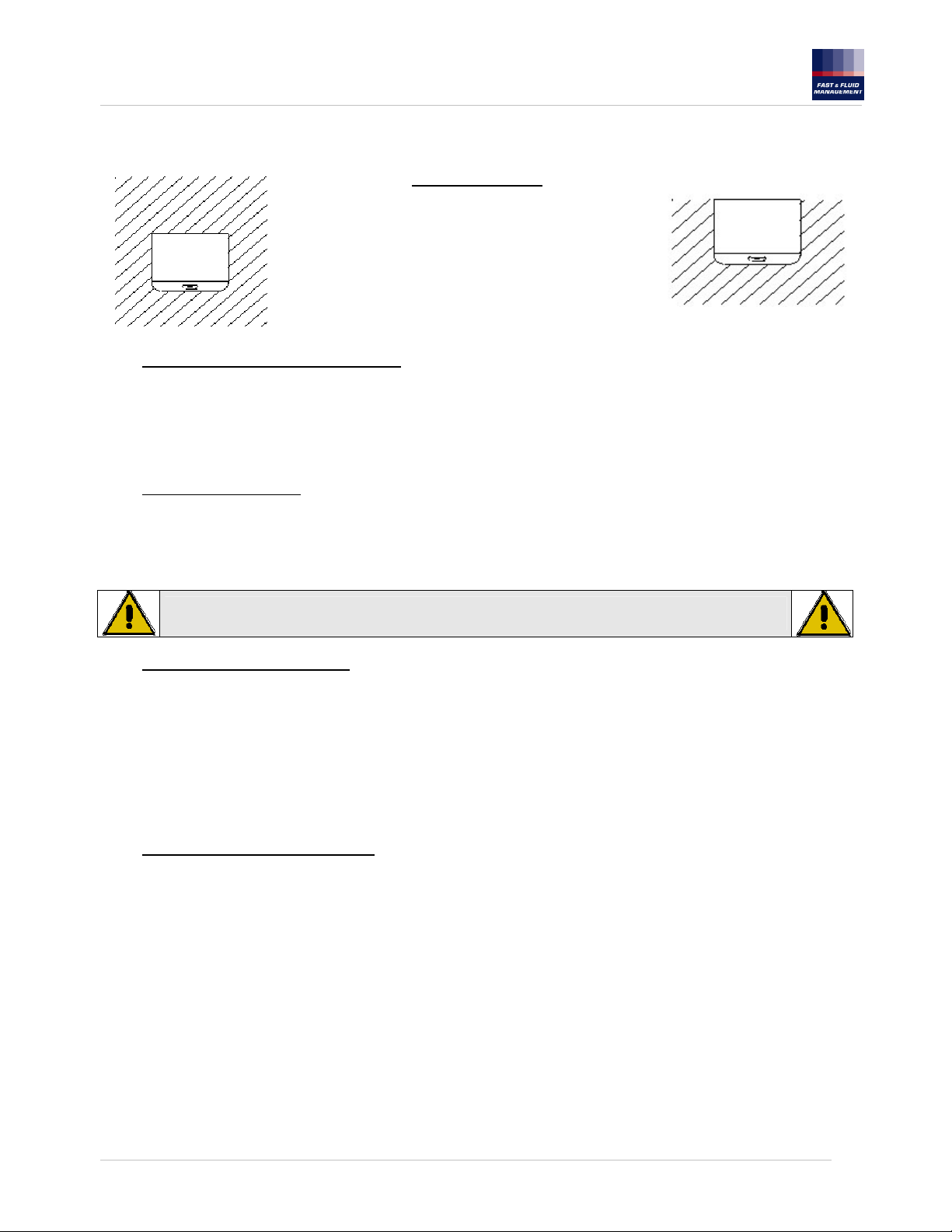
CONDIZIONI DI INSTALLAZIONE
Per l' installazione notare i punti seguenti:
Posizionare il Mixer Ferraris su un pavimento livellato e solido:
•
220-240 VOLT: Garantire un' alimentazione elettrica di 220/240V (o altrimenti specificato) che abbia una protezione
magnetotermica differenziale (30mA) da 16 Ampère e una rete di messa a terra secondo le Normative.
• 115 VOLT: Garantire un' alimentazione elettrica di 115V (o altrimenti specificato) che abbia una protezione magnetotermica
differenziale (30mA) da 25 Ampère e una rete di messa a terra secondo le Normative.
Le condizioni ambientali devono essere:
Temperatura ambiente : 10 a 40 °C
Umidità relativa : 30 a 90 %
Durante l’installazione è consigliabile utilizzare i guanti protettivi.
Questo Mixer Ferraris non può essere installato in un' area di lavoro classificata EX
Qualora sia necessario usare una prolunga, assicurarsi che la stessa sia
correttamente dimensionata tenendo conto dell’assorbimento elettrico del mixer.
Un solo il mixer (e quindi nessun altro macchinario) deve essere connesso ad un
singolo interruttore magne-totermico
1155432A-it,en,de.doc – 11/09/2006
8
Page 9
FAST & FLUID MANAGEMENT srl
A Unit of Idex Corporation
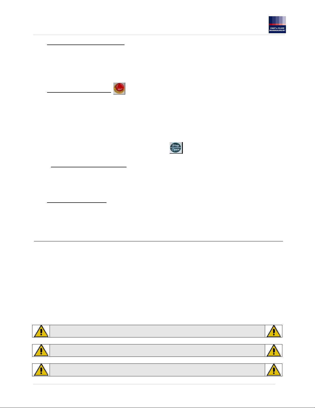
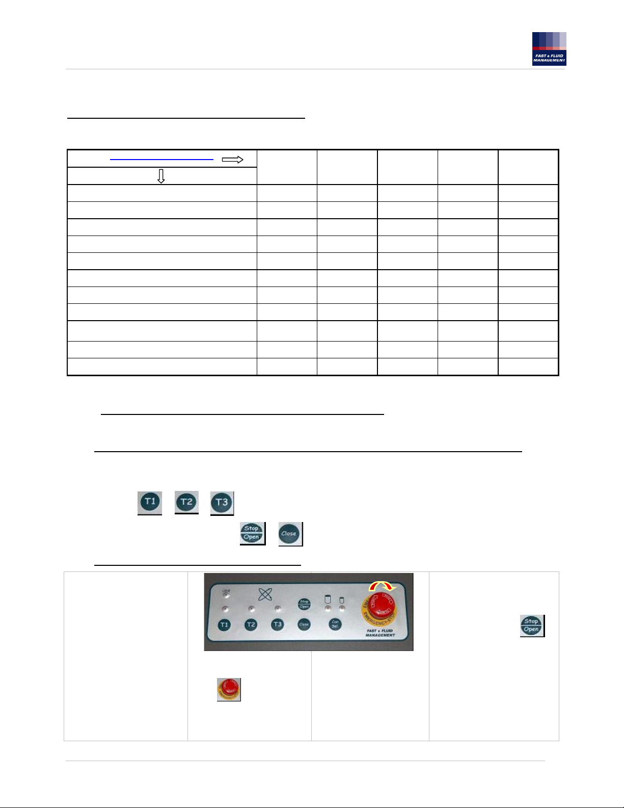
SPIA DI ALIMENTAZIONE
TASTIERA MIXER AUTOMATICO FERRARIS
PULSANTE “START” CON TEMPO 1
PULSANTE “START” CON TEMPO 2
PULSANTE “START” CON TEMPO 3
SPIA VELOCITA’ BASSA (Barattoli grandi)
SPIA VELOCITA’ ALTA (Barattoli piccoli)
PULSANTE DI SELEZIONE VELOCITA’
PULSANTE DI CHIUSURA PIATTI
PULSANTE “STOP” / APERTURA PIATTI
FUNGO DI EMERGENZA
1155432A-it,en,de.doc – 11/09/2006
9
Page 10
FAST & FLUID MANAGEMENT srl
A Unit of Idex Corporation
UTILIZZO DEL MIXER FERRARIS
ACCENSIONE MIXER FERRARIS
Foto A
APERTURA PORTINA APERTURA TAPPARELLA
Dopo l’avvenuto sblocco
è possibile aprire la portina
tirando la maniglia verso
destra come visualizzato in
figura
A macchina spenta la porta/tapparella non si apre.
Per accendere il mixer ruotare in posizione “1” l’interruttore principale (posizionato sul
lato posteriore della macchina) vedi foto A.. Per bloccare l’interruttore si può usare un
lucchetto.
Verificare che il pulsante di emergenza non sia premuto
Dopo l’avvenuto sblocco per
aprire la tapparella tirare
verso l’alto le apposite
maniglie
come visualizzato in figura
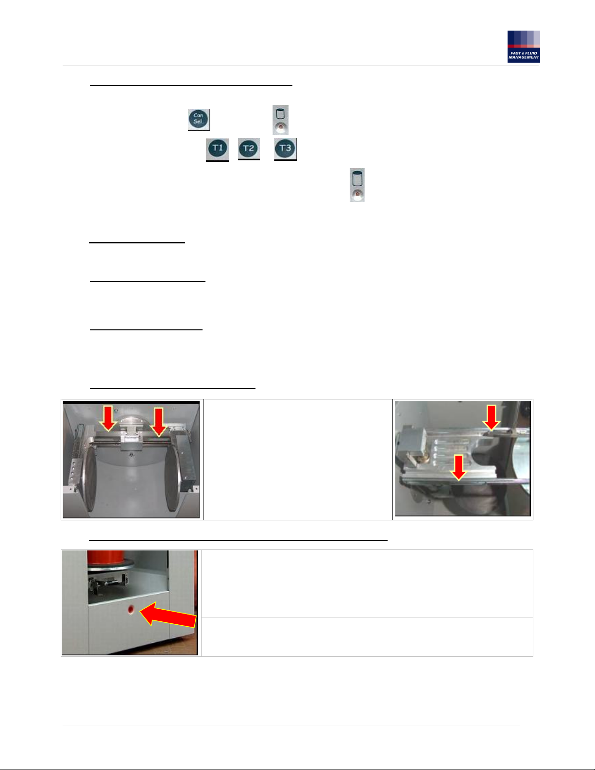
INSERIMENTO BARATTOLO
Aprire la porta/tapparella e premere la
leva posizionata sotto il piatto inferiore.
Vedi foto B.
AGITAZIONE BARATTOLO
1) Premere il tasto per selezionare una delle velocità
2) Avviare il ciclo di agitazione desiderato selezionando uno dei tasti o o con tempi
preimpostati
B
Estrarre il piatto inferiore per facilitare
il caricamento di barattoli superiori a 7
litri. Vedi foto C.
C
Posizionare il barattolo sul piatto inferiore e
premere nuovamente la leva per reinserire
il piatto all’interno della macchina (spingere
il piatto inferiore fino all’avvenuto
bloccaggio dello stesso). Vedi foto D.
Chiudere la porta/tapparella
D
1155432A-it,en,de.doc – 11/09/2006
10
Page 11
FAST & FLUID MANAGEMENT srl
A Unit of Idex Corporation
I due piatti mobili si avvicinano fino a premere il barattolo. Dopo circa 2 secondi inizia l’agitazione a velocità
ridotta. Trascorsi 5 secondi la velocità del cestello aumenta fino a regime
A tempo scaduto la velocità di rotazione diminuisce
Dopo la fase di decelerazione la macchina si ferma (fase di fermata con posizionamento a zero del cestello).
A cestello bloccato i due piatti si aprono ad è possibile estrarre il barattolo e ripetere l’operazione.
N.B. Con un barattolo di peso superiore a 10Kg non è abilitata l’agitazione a velocità massima
Premendo il tasto o o la macchina emette un segnale di errore e successivamente inizia
ad agitare a velocità lenta
3) Se il barattolo da agitare ha un’altezza superiore rispetto all’apertura del Mixer Ferraris, prima di aprire la
porta/tapparella bisogna aumentare la distanza dei piatti premendo il tasto
4) Se si vuole interrompere un ciclo appena avviato e non si è in una situazione di emergenza, usare il tasto
per interrompere il ciclo di agitazione.
Se non è necessario, evitare di utilizzare il pulsante di emergenza.
5) Se durante il funzionamento del Mixer Ferraris viene premuto il pulsante di emergenza, prima di riavviare un
nuovo ciclo di agitazione premere il tasto per riportare in posizione corretta il cestello. Se
quest’operazione non viene eseguita, premendo i tasti o o la macchina darà un segnale di
errore.
N.B. Dopo aver premuto il tasto di emergenza attendere che il cestello si fermi prima di effettuare qualsiasi altra
operazione.
6) A ciclo di agitazione terminato, ricordarsi di non lasciare il barattolo all’interno del cestello
a) Se dovesse mancare tensione mentre i piatti bloccano il barattolo, attendere il ripristino della linea ed il
cestello si riposizionerà automaticamente.
b) Se dovesse mancare tensione con barattolo inserito e piatti aperti, spegnere l’interruttore e togliere il
barattolo.
c) Se la porta/tapparella è chiusa, spegnere l’interruttore, aprire la porta/tapparella come indicato nel
successivo paragrafo.
7) Evitare di premere ripetutamente il pulsante
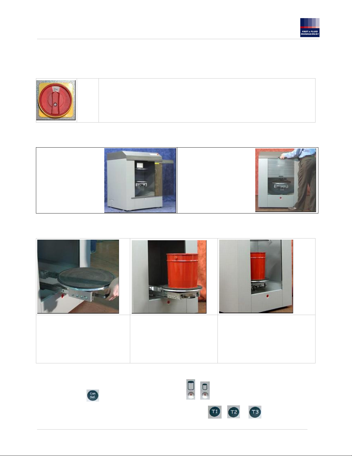
APERTURA DI EMERGENZA PORTINA
In caso di anomalie o mancanza di tensione di alimentazione la porta/tapparella è bloccata.
Se fosse necessaria l’apertura procedere come segue:
Inserire la punta di un cacciavite sotto la guida di
scorrimento porta/tapparella (come indicato da foto).
Premere il perno di blocco porta verso l’interno e
contemporaneamente aprire la porta/tapparella.
1155432A-it,en,de.doc – 11/09/2006
11
Page 12

FAST & FLUID MANAGEMENT srl
A Unit of Idex Corporation
ERRORI/ RICERCA GUASTI
La visualizzazione degli errori è possibile solo con l’Operator Panel (opzionale)
“E-0” ERRORE 0
- Pulsante di emergenza premuto
“E-1” ERRORE 1
- Porta aperta
“E-3” ERRORE 3
-a) Non sufficiente distanza tra barattolo e
piatto superiore
-b) Cinghia chiusura cestello allentata o rotta
-c) Sensore chiusura (su scheda Sensori
ottici) danneggiato o rotto
“E-4” ERRORE 4
-Cestello fuori posizione
“E-5” ERRORE 5
-Attuatore in posizione non corretta
“E-6” ERRORE 6
-Posizione di carico non raggiunta dopo la
ricerca
“E-8” ERRORE 8
-Premuto pulsante di emergenza durante il
funzionamento
“E-9” ERRORE 9
-Inverter in anomalia
1. Ruotare il pulsante di emergenza (sbloccarlo).
2. Controllare il collegamento dei fili sui contatti del fungo di
emergenza.
3. Cavo / cablaggio del Fungo di emergenza difettoso.
4. Scheda Logica difettosa.
1. Chiudere la porta.
2. Staffa di comando micro non in posizione (montata sulla
porta)
3. Micro-switch rotto
4. Cavo/cablaggio del microswitch o microswitch difettoso.
5. Scheda Logica difettosa.
1a. Aumentare la distanza premendo il tasto “STOP” prima
di iniziare il ciclo di agitazione
1b. Regolare cinghia o sostituirla.
1c. Pulire i sensori della scheda Sensori ottici
2c. Cavo tra scheda Logica – scheda Sensori ottici difettoso
3c. Scheda Sensori ottici difettosa
1. Prima di iniziare il ciclo di agitazione premere il tasto
“STOP”
1. Micro-switch attuatore rotto
2. Motore attuatore rotto
3. cavo microswitch / cavo motore attuatore difettosi
4. Scheda Controllo Attuatore / Logica difettose.
1. Spegnere la macchina per almeno 15 minuti. Se l’errore
dovesse ripresentarsi richiedere l’intervento di assistenza
2. Pulire i sensori della scheda sensori ottici
3. Scheda Sensori ottici difettosa
1. Se durante il ciclo di funzionamento è stato premuto il
pulsante di emergenza, premere STOP per poter riavviare
la macchina.
1. Tensione di rete tropo bassa o non stabilizzata
2. Se viene utilizzata una prolunga di alimentazione la
sezione del cavo è troppo piccola
3. Spegnere la macchina per 3-5 secondi poi riaccendere.
Se l’anomalia persiste richiedere l’intervento di assistenza
1155432A-it,en,de.doc – 11/09/2006
12
Page 13
FAST & FLUID MANAGEMENT srl
A Unit of Idex Corporation
. MANUTENZIONE E PULIZIA
Per qualsiasi intervento di manutenzione ed ispezione utilizzare guanti protettivi e spegnere il mixer Ferraris.
La manutenzione è da eseguirsi solo da personale addestrato.
Tabella manutenzione periodica.
Frequenza manutenzione
7 Giorni 1 Mese 6 Mesi 1 Anno 2 Anni
Operazione
Controllo elementi di sicurezza SI
Pulizia esterna SI
Pulizia interna SI
Lubrificazione guide verticali SI
Lubrificazione viti ed albero scanalato SI
Pulizia e lubrificazione corona dentata SI
Lubrificazione terna conica centrale
Lubrificazione ruota bloccaggio viti SI
Lubrificazione leva sbloccaggio ed alberi
carrello
Controllo stato dischi gommati SI
Controllo stato usura cinghie
12.2. Controllo elementi di sicurezza
SI
SI
SI
BLOCCOPORTA/TAPPARELLA (A macchina spenta e portina chiusa)
Tirando la maniglia, la porta/tapparella non deve aprirsi.
PORTA/TAPPARELLA (A macchina in tensione ma non funzionante; Spina inserita ed interruttore su “I”)
Appena accesa la macchina attende alcuni secondi per lo sblocco della porta/tapparella.
Aprire la porta/tapparella
Premendo i tasti o o , la macchina non deve funzionare ma dare un segnale di errore ( E-1)
Premendo i tasti di apertura e chiusura piatti o , la macchina non deve funzionare ma dare un segnale di errore
( E-1)
FUNGO DI EMERGENZA (A macchina funzionante)
Accendere la macchina
Aprire la porta/tapparella ed
inserire un barattolo vuoto
come indicato nell’apposito
capitolo, richiudendo la
porta/tapparella.
Selezionare una velocità e far
partire la macchina con un
tempo di lavoro qualsiasi.
Prima che il ciclo finisca,
premere il tasto di emergenza
rosso.
La rotazione deve arrestarsi
mentre la macchina darà un
segnale di errore (E-0 ).
Premere tutti i tasti ad
esclusione del tasto STOP;
Nessuno di essi dovrà
funzionare.
Premere il tasto STOP e
verificare che il cestello si
Il cestello si ferma in
posizione casuale con i piatti
chiusi e nessun tasto deve
funzionare
Riarmare il tasto di
emergenza ruotandolo in
senso orario.
riposizioni per poi aprire i piatti
Verificare che la portina venga
sbloccata.
1155432A-it,en,de.doc – 11/09/2006
13
Page 14
FAST & FLUID MANAGEMENT srl
A Unit of Idex Corporation
CONTROLLO VELOCITA’ (A macchina funzionante).
• Inserire un barattolo vuoto di altezza superiore ai 230 mm e richiudere la porta/tapparella.
•
Selezionare con il tasto la velocità alta
• Premere uno dei tasti di avvio t1 o o
•
Dopo la chiusura piatti la macchina darà un segnale di errore ( E-7)
• La macchina deve automaticamente iniziare il ciclo in velocità bassa .
Pulizia
Parti esterne e portina
Utilizzare un normale prodotto non abrasivo per la pulizia domestica di superfici lavabili.
Pannello comandi tastiera
Utilizzare un panno umido eventualmente con del sapone neutro asciugando senza risciacquare con un panno asciutto o carta
assorbente.
Parti interne (carrozzeria).
In caso di perdite di vernici, pulire immediatamente !
Se necessario togliere le parti secche con una spatola e successivamente utilizzare un normale prodotto non abrasivo per la
pulizia domestica di superfici lavabili.
Parti interne (gruppo cestello rotante).
In caso di perdite di vernici, pulire
immediatamente!
Se necessario togliere le parti secche con una
spatola.
Per pulire le parti lubrificate sarà sufficiente
utilizzare uno straccio che asporterà i residui di
vernice assieme al velo di lubrificante.
Ripristinare subito la lubrificazione secondo le
procedure in seguito illustrate.
Fuoriuscite accidentali di vernici interne e/o esterne al mixer Ferraris
Non usare getti d’acqua o pulitrice ad alta pressione per la pulizia del mixer Ferraris!
Non usare solventi per pulire il mixer Ferraris!
Se ciò fosse proprio indispensabile, arieggiare la macchina spenta con la porta/tapparella aperta per almeno 1 ora prima di
riutilizzarla
1155432A-it,en,de.doc – 11/09/2006
Pulire immediatamente la macchina ed il pavimento nella “Zona operatore” per evitare
rischi di scivolamento.
Svuotare la vasca di drenaggio svitando il tappo indicato e raccogliendo la vernice in un
contenitore basso.
Tappo drenaggio
14
Page 15
FAST & FLUID MANAGEMENT srl
A Unit of Idex Corporation
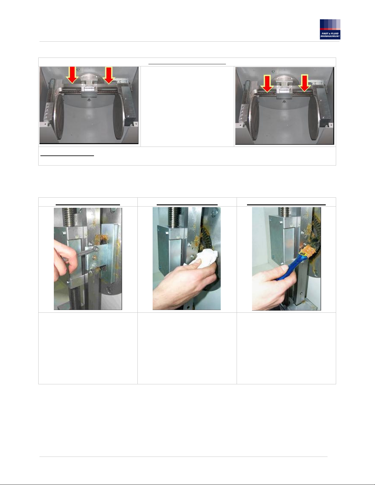
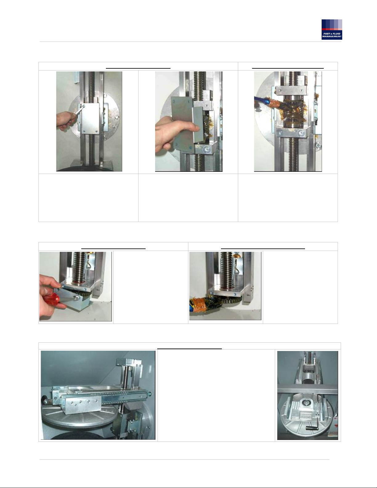
Lubrificazione guide verticali, viti ed albero scanalato.
Prodotti lubrificanti consigliati
Utilizzare un grasso giallo generico adesivo per ingranaggi scoperti, gradazione N.G.L.I. 2.
Preparazione macchina (prima fase)
Accendere la macchina con porta/tapparella chiusa
Chiudere completamente i piatti del cestello
Aprire la porta/tapparella e spegnere la macchina.
Asportare con uno straccio il vecchio lubrificante e gli eventuali residui di vernici
Ingrassaggio (prima fase)
Applicare il grasso con un pennello sulle
guide verticali
Sulle viti di comando piatti
Sulla barra scanalata
Preparazione macchina (seconda fase)
Chiudere la porta/tapparella ed accendere la macchina
Aprire completamente i piatti del cestello
Aprire la porta/tapparella e spegnere la macchina.
Ora è disponibile la parte centrale del cestello precedentemente coperta dai carri
Asportare con uno straccio il vecchio lubrificante e gli eventuali residui di vernici
1155432A-it,en,de.doc – 11/09/2006
15
Page 16
FAST & FLUID MANAGEMENT srl
A Unit of Idex Corporation
Ingrassaggio (seconda fase)
Opzione in alternativa
E’ possibile utilizzare anche del grasso confezionato in bombolette spray purché sia di tipo denso ed adesivo.
Pulizia e lubrificazione corona dentata
Ripetere l’operazione di ingrassaggio
per la porzione guide, viti ed albero
scanalato ora scoperti
Preparazione macchina Pulizia corona dentata Ingrassaggio corona dentata
Chiudere la porta/tapparella ed
accendere la macchina
Aprire completamente i piatti del cestello
Aprire la porta/tapparella e spegnere la
macchina.
Con una chiave fissa da 8 mm togliere le
viti dei due carter che proteggono la
corona dentata
Asportare con uno straccio il vecchio
lubrificante e gli eventuali residui di
vernici
1155432A-it,en,de.doc – 11/09/2006
Applicare il grasso con un pennello sulla
corona dentata
Ruotare a mano il cestello ripetendo
l’operazione di ingrassaggio su tutta la
corona dentata.
Verificare che il grasso riempia lo spazio
tra i denti
Rimontare nella posizione originaria i due
carter.
16
Page 17
FAST & FLUID MANAGEMENT srl
A Unit of Idex Corporation
Lubrificazione terna conica centrale.
Preparazione macchina Ingrassaggio terna conica
Chiudere la porta/tapparella ed
accendere la macchina
Aprire completamente i piatti del cestello
Aprire la portina e spegnere la macchina.
Con una chiave fissa da 8 mm togliere le
viti del carter che protegge la terna
conica
Asportare il grasso vecchio con uno
straccio
Lubrificazione ruota bloccaggio viti.
Preparazione macchina Ingrassaggio ruota bloccaggio
Chiudere la porta/tapparella
ed accendere la macchina
Chiudere completamente i
piatti del cestello
Aprire la porta/tapparella e
spegnere la macchina.
Con una chiave fissa da 8 mm
togliere le viti del carter che
protegge la ruota dentata
Lubrificazione leva sbloccaggio ed alberi carrello.
Preparazione macchina
Chiudere la porta/tapparella ed accendere la
macchina
Chiudere completamente i piatti del cestello
Aprire la porta/tapparella e spegnere la macchina
Ruotare a mano il cestello di mezzo giro
Premere la leva, estrarre il carrello e bloccarlo.
Applicare il grasso con un pennello sugli
ingranaggi conici
Verificare che il grasso riempia lo spazio
tra i denti
Rimontare nella posizione originaria i due
carter.
Asportare il grasso vecchio
con uno straccio
Applicare il grasso con un
pennello sulla ruota dentata
Verificare che il grasso riempia
lo spazio tra i denti
Rimontare nella posizione
originaria il carter.
1155432A-it,en,de.doc – 11/09/2006
17
Page 18

FAST & FLUID MANAGEMENT srl
A Unit of Idex Corporation
Ingrassaggio leva bloccaggio ed alberi carrello estrazione
Applicare il grasso con un
pennello sulla leva e sulla
cave indicate.
Applicare un velo sottile di
grasso nelle guide di
scorrimento del carrello.
Far scorrere il carrello e
ripetere l’operazione per
favorire la lubrificazione nelle
porzioni coperte.
Controllo stato dischi gommati.
Preparazione macchina Controllo stato dischi gommati
Chiudere la porta/tapparella ed accendere
la macchina
Aprire completamente i piatti del cestello
Aprire la porta/tapparella
Estrarre il carrello
Pulire i piatti
Controllo stato usura cinghie.
Preparazione
macchina
Chiudere la
porta/tapparella ed
accendere la
macchina.
Chiudere
completamente i piatti
del cestello.
Aprire la
porta/tapparella e
spegnere la macchina
Con una chiave fissa da 8 mm togliere le quattro viti del carter che
protegge la cinghia dentata ed asportarlo
Verificare che il disco inferiore non
presenti solchi eccessivamente
profondi o consumi non uniformi
Verificare che il disco superiore non
presenti solchi eccessivamente profondi o
consumi non uniformi
Controllo cinghia trasmissione piatto superiore
Verificare l’integrità della cinghia
dentata
La cinghia non deve presentare
denti rotti o sfilacciature
Rimontare il carter nella
posizione originaria
1155432A-it,en,de.doc – 11/09/2006
18
Page 19

FAST & FLUID MANAGEMENT srl
A Unit of Idex Corporation
Controllo cinghia trasmissione principale
ATTENZIONE:
PRIMA DI RIMUOVERE IL PANNELLO POSTERIORE
LEVARE L’ALIMENTAZIONE DI CORRENTE ELETTRICA
ALLA MACCHINA.
DOPO AVERE TOLTO L’ALIMENTAZIONE DI CORRENTE
ELETTRICA, ATTENDERE CINQUE MINUTI PRIMA DI
ACCEDERE ALLE SCHEDE ELETTRONICHE.
Accertarsi che non ci siano barattoli nel cestello.
Spegnere il mixer Ferraris agendo sull’interruttore rotativo
posteriore.
Per asportare il pannello, sollevarlo mediante l’aiuto dei due
fori come indicato in figura e contemporaneamente tirarlo
verso l’esterno
Verificare la tensione della cinghia che deve flettere di 5 ÷ 10
mm alla pressione delle dita sul lato libero più lungo.
Eventualmente ripristinare la tensione corretta agendo sul
bullone (13 mm) indicato in figura.
Usando un misuratore di tensione elettronico (basato sulla
rilevazione delle onde sonore) verificare che la cinghia di
trasmissione verticale abbia una frequenza di circa 90Hz, e la
cinghia di trasmissione orizzontale abbia una frequenza di
circa 125Hz.
Verificare l’assenza di sfilacciature su tutta la cinghia facendo
ruotare a mano la puleggia centrale.
Rimontare il pannello posteriore nella condizione originaria
1155432A-it,en,de.doc – 11/09/2006
19
Page 20

FAST & FLUID MANAGEMENT srl
OTTICI
A Unit of Idex Corporation
SCHEDA
CONTROLLO
ATTUATORE
SCHEMA FUNZIONALE 115 - 230V
SCHEDA
SENSORI
SCHEDA
LOGICA
FILTRO + CAVO
SCHEDA INVERTER
1155432A-it,en,de.doc – 11/09/2006
20
Page 21

FAST & FLUID MANAGEMENT srl
A Unit of Idex Corporation
SCHEMA ELETTRICO 115 - 230V
1155432A-it,en,de.doc – 11/09/2006
21
Page 22

FAST & FLUID MANAGEMENT srl
A Unit of Idex Corporation
ENGLISH
OPENING STATEMENT
This FAST& FLUID MANAGEMENT Srl Ferraris Mixer represents the very latest in High Speed Paint mixing
technology. As a result, your FAST Ferraris Mixer is a rugged and reliable mixer which performance and design
exhibits the qualities of a strong and sturdy engineering product.
To fully appreciate and protect your investment, we suggest that you take the necessary time to read and fully
understand this manual.
As, always, FAST & FLUID MANAGEMENT Srl stands behind your unit with a one year limited warranty, and a
dedicated service organization.
The few maintenance operations as mentioned in this manual need to be carried out on a regular bases.
FAST & FLUID MANAGEMENT Srl shall not be liable for any damage or injury incurred by noncompliance with these regulations, or by not taking the usual and accepted precautions in
handling, operation or repair, even if expressly stated in this manual.
Ferraris Mixer must not be switched on if it has not been earthed through one or
both of the earth connection points (socket and/or earth/ground bolt).
The information contained in this manual is property of FAST & FLUID MANAGEMENT Srl . This manual has been
prepared expressly for the purpose of assisting in the use and general maintenance of this equipment.
Publication of this information does not imply any right to reproduce or use this manual for purposes other than installing,
operating, or maintaining this equipment.
No part of this manual may be reproduced, translated, stored in a retrieval system, or translated into any language or
computer language, in any form or by any means, without the prior written permission of an officer of FAST & FLUID
MANAGEMENT Srl.
The FAST & FLUID MANGEMENT Srl high speed Ferraris Mixer is specially designed for point of sale color mixing
applications as well as for semi industrial applications.
The FAST & FLUID MANAGEMENT Srl high speed Ferraris has been designed to meet the demand of the retail
market with a reduced clamping clearance and for the professional market with a maximum clamping clearance of
495 mm.
The unique design enables to reduce maintenance to a minimum and therefore allows color mixing to be performed
at a low cost per liter produced.
The equipment features an automatic clamping and mixing cycle. The user of the FAST & FLUID MANAGEMENT
Srl high speed paint Ferraris Mixer can select the preferred mixing time on a membrane electronic pad.
Use two different stirring velocity for cans: 100 turns/min. e 200 turns /min.
PROPRIETARY NOTICE
GENERAL DESCRIPTION
1155432A-it,en,de.doc – 11/09/2006
22
Page 23

FAST & FLUID MANAGEMENT srl
A Unit of Idex Corporation
SAFETY SPECIFICATIONS
WORKING AREA
MAINTENANCE AREA
OPERATOR AREA
Compliance with security requirements
The machine must be used and serviced by trained personal only ,because it is possible that a wrong use can
introduce dangers and cause accidents.
The main areas in which can be present risks are:
Working area
Maintenance area
Power supply
220-240 VOLTAGE: The Ferraris Mixer must be connected to a voltage of 220 - 240 Volt (or otherwise specified following local
situations), which has a differential (MINIMUM 30mA), a magnetothermic protection of 16 Amp and a grounded outlet according
to local regulations.
115 VOLTAGE: The Ferraris Mixer must be connected to a voltage of 115 Volt (or otherwise specified following local situations),
which has a differential (MINIMUM 30mA), a magnetothermic protection of 25 Amp and a grounded outlet according to local
regulations.
THE ACCESS TO THE ELECTRICAL WIRING IS ALLOWED TO SKILLED PEOPLE ONLY.
DON’T WORK WITH THE MACHINE IF BACK PANEL IS OFF.
Safe use of the machine
The manufacturer has adopted all measures and attentions projecting, drawing manufacturing , checking , installing , starting and
defining the procedures for using its products, to guarantee the highest possible level during a rational use of the supplied
system. The components are in conformity to the recent security rules. Updated security equipments are installed to assure the
maximum security level that it is available today.
When using the FAST & FLUID MANAGEMENT Srl Ferraris Mixer, the following safety regulations need to be observed:
The "user" is expected to follow all local safety regulations. If there is a contradiction in European regulations and local
regulations, the demands of the most severe legislation must be met.
The installation and the maintenance of the Ferraris Mixer have to be performed by a specialized technician
Service safety rules
1. To prevent any physical injuries all outside panels should always be in place on the Ferraris Mixer and properly secured.
2. Don’t touch protections system as speed control and blocking security closing door/shutter.
3. Prior to any maintenance and inspection of the Ferraris Mixer: disconnect the power cord from the outlet mains. Make sure
that the Ferraris Mixer cannot be started unexpectedly.
4. Do not leave any tools inside in the Ferraris Mixer after maintenance.
5. Check that the environment where the machine is installed conforms to local regulations (a permit issued by the fire marshall
or by local autority may be necessary) and avoid dangerous concentration of paint cans around the equipment. It’s forbidden
to stock inflammable materials or other materials inside the machine. It’s forbidden to use free flames, incandescent objects or
equipments able to create sparks in the local where the machine is installed.
6. It is recommended to install a ventilation system to guarantee that the concentration of dangerous vapours around all
electrical components is less than 30%.
7. At the end of the work avoid keeping free cans inside the machine and avoid keeping the machine switched on if it isn’t used.
8. If the machine is switched on but it isn’t stirring inside it, there isn’t residual mechanical energy because the inverter is switched
off.
9. In the locations where the Mixer Ferraris is installed the prohibition symbols “no smoking” have to be present placed at 5 meters
from the machine.
1155432A-it,en,de.doc – 11/09/2006
23
Page 24

FAST & FLUID MANAGEMENT srl
A Unit of Idex Corporation
The equipment was built for the treatment of not explosive materials. it’ is forbidden to use
this machine with flammable or explosive vapours.
Avoid to operate the Ferraris Mixer without a clamped load.
Never use a load with a weight over 40 Kg.
Don’t switch-off the machine with the can inside.
Do not place any damaged packaging in the Ferraris Mixer.
Further rupture during mixing may cause damage to the Ferraris Mixer
Running the Ferraris Mixer with damaged packaging is at "User's" risk.
Already damaged packaging may cause damage to the your machine.
During the maintenance respect the security rules and the procedure described in its paragraph.
The Ferraris Mixer is to be operated only by trained personnel. FAST & FLUID MANAGEMENT shall not be liable for
any damage or injury caused by non - compliance with the "user"- and "safety" - regulations presented in this manual,
or by not taking the usual and accepted precautions in handling, operation or repair, even if not expressly stated in
This is also valid for damage and/or accidents as a result of changes made to the machine, that are implemented without
prior notice to and approval by FAST & FLUID MANAGEMENT Srl.
Residual risks list for the operator
Even if all attentions have been paid during the designing of the machine to guarantee a safety use it is possible to find situations
rationally foreseeable for which it has been possible only to reduce the risk but not to eliminate it completely.
RISK DIRECTIVE 392 PRECAUTION
Injuries or crushing during loading and
unloading operations
Abrasions and injuries caused by sharp
edges and parts of the cans to use
Liquid leakages from the cans Clean carefully the area where the operator works.
Residual risks for the maintenance people
RISK DIRECTIVE 392 PRECAUTION
Danger of electrocution during the setting
phases of the inverter
Personal protection for user
If the equipment is used in a correct way , the machine does not present risks or dangers for the operator , which in any
case has to wear individual protection devices (security glasses, anti-sliding shoes, protective gloves ) specially during
the loading and unloading phases of the cans.
General danger situations
There aren’t any particular danger situations ( E.G.. Fire risk, issue/ dispersion of dangerous products) but in any case it is
necessary to have a powder extinguisher for possible fire situations. (electrical equipments).
Warning:
this manual.
RESIDUAL RISK
1.6.4
4.1.1
1.6.4
4.1.1
1.5.1
1.5.2
Use security protective gloves and shoes during loading and
unloading operations
Use protective gloves during loading and unloading
operations
Use security shoes.
Position protective screen for the dangerous terminal blocks
1155432A-it,en,de.doc – 11/09/2006
24
Page 25

FAST & FLUID MANAGEMENT srl
A Unit of Idex Corporation
Security components and devices
The machine is equipped with the following security devices:
•
An emergency push button
• A blocking door/shutter device
•
For security reasons,it is recommended that all users know the positions and the modalities to use the red emergency
push button.
The emergency RED push button is assembled on the operator panel on the right part of the system. The pressing of this push
button permits the immediate cut off of the power supply and the stopping of the motor rotation . The restore of the normal
functioning of the equipment is possible rotating the emergency push button in clockwise direction . In case of emergency
stopping during the working cycle it is necessary execute the resetting procedures pushing STOP KEY .
The machine is equipped with a security device which doesn’t permit the starting of the cycle if the door/shutter is in loading
position. During the working cycle the security device doesn’t permit the opening of the door/shutter.
On the machine is positioned a sensor able to notice the presence of a can with a high superior to 200 mm. The control system
guarantees rotation regime of 100g/m for cans with high superior to this dimension, it permits, on the contrary, rotation of 100
or 200 rpm for cans with high inferior to this dimension . This situation guarantees a correct dynamic arrangement of the
equipment . If the operator set a high velocity with a big can the system gives an error signal and it starts the rotation with a
suitable velocity.
A sensor for improper use of the rotation velocity
Emergency push button
Open door/shutter sensor
Speed control sensor
INSTALLATION CONDITIONS
Before installation please make sure of the following:
Place the Ferraris Mixer on a firm and leveled floor
• 220-240 VOLTAGE: Provide a grounded power supply of 220 / 240 Volt (or otherwise specified following local situations),
which has a differential (MINIMUM 30mA), a magnetothermic protection of 16 Amp.
•
115 VOLTAGE: Provide a grounded power supply of 115 Volt (or otherwise specified following local situations), which has a
differential (MINIMUM 30mA), a magnetothermic protection of 25 Amp.
Environmental conditions should be within the following limits:
Relative humidity : 30 to 90 %
During the installation it is advisable to use protective gloves to avoid hand injuries
Ambient air temperature : 10 to 40 °C
This mixer must not be installed in an explosion proof classified working area
In case an extension is needed, please make sure it is correctly dimensioned,
according to the electrical absorption of the mixer
One mixer only (therefore no other machinary) is to be connected to a single
magnetothermic switch
1155432A-it,en,de.doc – 11/09/2006
25
Page 26

FAST & FLUID MANAGEMENT srl
A Unit of Idex Corporation
POWER LIGHT
MIXER FERRARIS KEYBOARD
“START” BUTTON (With time 1)
“START” BUTTON (With time 2)
“START” BUTTON (With time 3)
LOW SPEED LIGHT (Big can)
HIGHT SPEED LIGHT (Small can)
SELECTION SPEED BUTTON
CLOSING PLATES BUTTON
“STOP” BUTTON / OPENING BUTTON
EMERGENCY PUSH BUTTON
1155432A-it,en,de.doc – 11/09/2006
26
Page 27

FAST & FLUID MANAGEMENT srl
A Unit of Idex Corporation
USE OF THE FERRARI MIXER
SWITCHING MIXER FERRARIS ON
The door/shutter doesn’t open when the machine is switched off.
Photo A
OPENING DOOR/SHUTTER OPENING SHUTTER
Open the door/shutter
pulling the handle to the
right (as shown in the
figure)
To switch the machine on turn in position “1” the main switch (positioned on the back
side of the machine). See photo A.. To lock the switch, a locker must be used.
Verify that the emergency push button is not pushed
Open the shutter pulling up
the handle (as shown in the
figure)
LOADING THE CAN IN THE MIXER
Open the door/shutter and press the lever
positioned below the inferior plate. See
photo B.
MIXING PAINT CANS
1) Set the desired mixing speed using the key
2) Start mixing cycle using or or (three preset times)
B
Extract the lower plate to facilitate
loading of heavier cans. See photo C.
C
Position the can on the inferior plate and
press again the lever to push the plate
back inside the machine (Push the inferior
plate until it locks inside the machine). See
photo D. Now close the door/shutter.
D
1155432A-it,en,de.doc – 11/09/2006
27
Page 28

FAST & FLUID MANAGEMENT srl
A Unit of Idex Corporation
The two mobile plates move untill the can is pressed . After about 2 seconds the mixing cycle begins at slow
velocity. After 5 seconds the velocity of the can increases until it reaches the desired mixing velocity.
When the set time is expired the rotation velocity decreases
After the deceleration phase the machine stops.
When the stirring cycle is finished and the can is motionless the two plates open and it is now possible to extract
the can.
N.B.
It is not possible to perform the mixing cycle at the maximum velocity with cans which weighs more
than 10 Kg.
Pushing the or or keys, the machine indicates an error (E-7) and automatically the
machine begins to operate at slow velocity
3) If the can to be mixed is higher than the opening clearance of the plates, it is necessary to open the distance
between the plates pushing key before opening the door/shutter.
7) To stop the mixer during non-emergency situation, press the STOP key .
8) If during the functioning of the Mixer Ferraris the emergency push button is pushed down, push the key
N.B. After pushing the emergency button, before activating any operation please wait till the cradle stops completely.
9) When the mixing cycle is finished, remember not to keep the can inside the basket
7) Avoid to go on pressing and releasing key
EMERGENCY DOOR/SHUTTER OPENING
In case of malfunctioning or absence of power supply the door/shutter is blocked.
To open the door/shutter operate as follows:
Unless necessary, please do not use the emergency push button .
STOP before starting a new mixing cycle. Failure to do so will generate an error (E-4) when pressing the
or or keys.
b If the power supply is off with the can inside , switch off the main switch and take away the can.
a) If the power supply is off when the plates block the can, wait for the setting of the line and the cradle will
position itself automatically
If the door/shutter is closed, turn off the switch, open the door/shutter as indicated in the “EMERGENCY
DOOR/SHUTTER OPENING” and take away the can.
Insert the point of a screw-driver under the
sliding door/shutter guide ( as indicated)
Push the block-pin and pull the door/shutter to
the right.
1155432A-it,en,de.doc – 11/09/2006
28
Page 29

FAST & FLUID MANAGEMENT srl
A Unit of Idex Corporation
TROUBLESHOOTING
It is possible to display error using Operator Panel (optional)
“E-0” ERROR 0
- Emergency push button – pushed down
“E-1” ERROR 1
- Open door/shutter
“E-3” ERROR 3
-a) Distance between can and superior plate
not sufficient
-b) Loosen/broken belt for closing plates
-c) Damaged/broken sensor for closing (on
optic sensor board)
E-4” ERROR 4
- Wrong position of the mixing apparatus
“E-5” ERROR 5
- Actuator faulty position
“E-6” ERROR 6
- Unable to find loading position
“E-8” ERROR 8
- The emergency push button is pressed
during the functioning
“E-9” ERROR 9
- Anomaly of the inverter
1. Turn the emergency push button clockwise
2. Check the wires connection on the emergency
push button
3. Defective emergency push button wire/cable
4. Defective Logic Board
1. Close the door/shutter
2. Microswitch bracket out of position (assembled on the
door/shutter)
3. Broken microswitch
4. Defective wire/cable of the microswitch
5. Defective Logic Board
1a. Increase the distance pressing the key STOP before
beginning the stirring cycle.
1b. Regulate the belt or replace it.
. Clean the sensor on the Optic Sensor Board
1c
2. Defective cable between Logic Board and Optic Sensor Board
3. Defective Optic Sensor Board
1. Before starting the mixing cycle push the “STOP” key
1.Broken actuator switch
2.Broken actuator
3. Defective cable of the micro switch.
4. Defective Logic Board
1. Switch off the machine for 15 minutes. If the error appears
again call for assistance in replacing the broken micro switch
of the actuator
2. Clean or replace the sensor of zero position
3. Defective Optic Sensor Board
If during the mixing cycle the emergency push button is
1.
pressed , push STOP to restart the machine.
1. Power supply too low or not stabilized
2. Extension cord is used.
Switch off the machine for 3-5 seconds and then switch it
3.
again. If the problem persist call for assistance.
1155432A-it,en,de.doc – 11/09/2006
29
Page 30

FAST & FLUID MANAGEMENT srl
cle ends, push
The rotation has to stop
while the machine indicate an
A Unit of Idex Corporation
MAINTENANCE AND CLEANING
For any maintenance operation or inspection use protective gloves and switch off the mixer Ferraris.
Only trained personal can execute maintenance operations
Periodical maintenance list
Maintenance frequency
Operations
Check of the security elements
Outside cleaning
Inside cleaning
Lubrication vertical guides
Lubrication screws and shaft
Cleaning and lubrication of the
Crown gear
Lubrication conical triad
Lubrication blocking screws wheel
Lubrication unblocking lever and trolley
shafts
Check of the rubber disks
Check of the belts
Check of the security elements
7 days 1 month 6 months 1 year 2 years
YES
YES
YES
YES
YES
YES
YES
YES
YES
YES
YES
BLOCKING DOOR/SHUTTER ( with switched off machine and closed door/shutter )
Pulling the handle , the door/shutter hasn’t to open.
DOOR/SHUTTER (The machine is switched on but it doesn’t work; Connected plug and turn the switch on “I”)
When the machine is switched on
Open the door/shutter
Pushing or or , the machine hasn’t to work , but it has to indicate an error (E-1).
Pushing the opening and closing keys of the plates or , the machine hasn’t to work , but it has to
indicate an error (E-1).
EMERGENCY PUSH BUTTON (Working machine)
Switch on the machine.
Open the door/shutter and
insert an empty can as
indicated in the specific
chapter. Then close the
door/shutter.
Push or or
to start the machine.
1155432A-it,en,de.doc – 11/09/2006
attend some seconds for the release of the door/shutter
Before the cy
the red emergency push
button.
error (E-0).
The cradle stops with the
closed plates and no key
has to work.
Set the emergency push
button turning it in clock
wise direction.
Push all the keys except from
the key STOP. No key should
be operational.
Push the key STOP
and verify that the cradle
position to permit to the plates
to open.
Verify that the door/shutter is
unlocked.
30
Page 31

FAST & FLUID MANAGEMENT srl
A Unit of Idex Corporation
SPEED CHECK (With working machine).
• Insert an empty can with a high superior to 230 mm. and close the door/shutter.
• Set the high mixing speed using the key
• Push the key start or or
•
After the closing of the plates the machine indicates an error (E-7).
•
The machine has automatically to start the cycle with a slow velocity
Cleaning
Outside parts of the door/shutter
Use a normal not abrasive product for the cleaning of the washable domestic surfaces.
Use a wet cloth with neutral soap and dry without rinsing with a dried cloth or absorbent paper.
If there are paint leakages, clean immediately !
If necessary take away the dried part using a paddle and then use a normal not abrasive product for the cleaning of washable
domestic surfaces.
Command panel , keyboard
Inside parts (frame).
Inside parts (turning basket group).
If there are paint leakages, clean immediately !
If necessary take away the dried part using a
paddle.
To clean the lubricated parts it will be sufficient
to use a cloth able to take away residual paint
parts and a little part of lubricant product.
Lubricate immediately following the procedures
below shown .
Accidental inside and/ or outside paint leakages
Don’ t use water jet or polishing machine with high pressure to clean the mixer Ferraris!
Don’ t use solvent to clean mixer Ferraris!
If the use of solvent is necessary , keep the machine switched off with the door/shutter open for 1 hour before using it.
Clean immediately the machine and the floor in the “operator area” to avoid sliding
risks.
Empty the drainage tank unscrewing the cap indicated and picking up the paint in a
low container.
Drainage cap
1155432A-it,en,de.doc – 11/09/2006
31
Page 32

FAST & FLUID MANAGEMENT srl
A Unit of Idex Corporation
Lubrication of the vertical guides, screws and shaft.
Advised lubricant products
Use a yellow adhesive generic grease for uncovered gears, gradation N.G.L.I. 2.
Preparation of the machine (first phase)
Switch on the machine with the door/shutter closed.
Close completely the cradle plates.
Open the door/shutter and switch off the machine.
Clean using a cloth the old lubricant and the possible residual paint
Greasing (first phase)
Grease the vertical guides using a brush.
Grease the plates command screws.
Grease the shaft
Preparation of the machine (second phase)
Close the door/shutter and switch on the machine
Open completely the cradle plates
Open the door/shutter and switch off the machine.
Now it is available the central part of the cradle that previously is covered by the guides.
Clean using a cloth the old lubricant and the residual paint
Greasing (second phase)
Alternative operation
It is possible to use spray grease too, but it has to be thick and adhesive
Repeat the greasing operation for the
part of the guides, screws and shaft
that now are discovered.
1155432A-it,en,de.doc – 11/09/2006
32
Page 33

FAST & FLUID MANAGEMENT srl
A Unit of Idex Corporation
Cleaning and lubrication of the crown bevel gear
Preparation of the machine Cleaning of the crown gear Greasing of the crown gear
Close the door/shutter and switch on the
machine
Open completely the cradle plates
Open the door/shutter and switch off the
machine.
Using a key of 8 mm. remove the screws
of the two protections of the crown bevel
gear.
Remove the old lubricant and the
residual paints using a cloth
Lubrication of the central triple gear group.
Preparation of the machine
Put the grease on the crown bevel gear
using a brush
Turn manually the cradle repeating the
greasing on all the crown bevel gear.
Verify that the grease cover the space
among the teeth .
Assemble again the two protections in
their position
Greasing of the triple gear group
Close the door/shutter and switch on the
machine
Open completely the cradle plates
Open the door/shutter and switch off the
machine
By using an 8 mm key, remove the
screws of the protection of the triple gear
group
Remove the old grease with a cloth
Put the grease on the conical gears
using a brush
Verify that the grease cover the space
among the teeth
Assemble again the two protections in
their position
1155432A-it,en,de.doc – 11/09/2006
33
Page 34

FAST & FLUID MANAGEMENT srl
A Unit of Idex Corporation
Lubrication of the blocking screws wheel.
Preparation of the machine Greasing of the blocking wheel
Close the door/shutter and
enter in the machine
Close completely the cradle
plates
Open the door/shutter and
switch off the machine
Using a key of 8 mm. remove
the screws of the toothed
wheel
Lubrication of the unblocking lever and shafts of the trolley.
Preparation of the machine
Remove the old grease by
using a cloth
Put the grease on the toothed
wheel using a brush
Verify that the grease cover
the space among the teeth
Assemble again the protection
in its position.
Close the door/shutter and switch on the machine
Close completely the cradle plates
Open the door/shutter and switch off the machine
Turn manually the cradle of half a turn
Push the lever, take out the trolley and block it.
Blocking lever gear and shafts for taking out the trolley
Grease the lever and slots with a
brush
Grease the shafts of the trolley
using a brush
Move the trolley and repeat the
operation on previously covered
part of the shaft
1155432A-it,en,de.doc – 11/09/2006
34
Page 35

FAST & FLUID MANAGEMENT srl
A Unit of Idex Corporation
Check of the rubber disks
Preparation of the machine
Close the door/shutter and
switch on the machine
Open completely the cradle
plates
Open the door/shutter
Take out the trolley
Clean the plates
Check of the rubber disks
Check of the belts
Preparation of the
machine
Close the door/shutter
and switch on the
machine
Close completely the
plates of the cradle
Open the door/shutter
and switch off the
machine
Verify that the inferior disk hasn’t deep
grooves or it is excessively worn
Check of the transmission belt of the upper plate
Using a key of 8 mm remove the four screws of the protection
which cover the timing belt and remove it.
Verify that the upper plate hasn’t deep grooves
or it is excessively worn
Check the timing belt. It must not
to have broken teeth or grindings
Assemble the protection in its
original position
1155432A-it,en,de.doc – 11/09/2006
35
Page 36

FAST & FLUID MANAGEMENT srl
A Unit of Idex Corporation
Check of the main transmission belt
ATTENTION:
BEFORE REMOVING THE BACK PANEL, UNPLUG THE
MACHINE FROM ELECTRIC POWER SUPPLY.
ONCE UNPLUGGED THE MACHINE, WAIT FOR AT LEAST
FIVE MINUTES BEFORE ACCESSING THE ELECTRONIC
BOARDS.
Make sure that there isn’t any can in the cradle
Turn off mixer Ferraris (rear main switch)
Remove the back panel, lift it up by using the two holes (as
shown in the picture) while pulling it towards you
Make sure that the tension of the belt has to have a bending
of 5 ÷ 10 mm when the longer free part is pushed by a finger.
If necessary tension the belt by using the bolt (mm 13)
indicated
By using a belt tension tester (which operates by measuring
sound waves), make sure that frequency of the vertical
transmission belt is about 90Hz, and that frequency of
horizontal transmission belt is about 125Hz.
Verify that the belt hasn’t any grindings while turning manually
the central pulley
Assemble the back panel to its original position.
1155432A-it,en,de.doc – 11/09/2006
36
Page 37

FAST & FLUID MANAGEMENT srl
BOARD
INVERTER BOARD
A Unit of Idex Corporation
ACTUATOR
CONTROL
BOARD
LOGIC BOARD
FUNCTIONAL DIAGRAM 115 - 230V
OPTICAL
SENSORS
CABLE + FILTER
1155432A-it,en,de.doc – 11/09/2006
37
Page 38

FAST & FLUID MANAGEMENT srl
A Unit of Idex Corporation
ELECTRICAL DIAGRAM 115 - 230V
1155432A-it,en,de.doc – 11/09/2006
38
Page 39

FAST & FLUID MANAGEMENT srl
A Unit of Idex Corporation
Der Mixer Ferraris FAST & FLUID MANAGEMENT Srl ist das Resultat modernster Technologie im Bereich der
Lackmischung bei Hochgeschwindigkeit. Ihr Mixer Ferraris FAST & FLUID MANAGEMENT ist ein stabiles und
zuverlässiges Mischgerät, Funktionsweise und Design beweisen akkurate Planung und Bau des Produkts.
Um Ihre Anschaffung bestmöglich zu nutzen und zu schützen ist es ratsam, sich die Zeit zum Lesen der vorliegenden
Betriebsanweisungen zu nehmen.
Wie immer gewährt Ihnen FAST & FLUID MANAGEMENT eine einjährige Garantie auf das Produkt und bietet einen
spezifischen Kundenservice.
Die wenigen Wartungsarbeiten, die nachfolgend in den Anweisungen genannt werden, müssen regelmäßig
durchgeführt werden.
FAST & FLUID MANAGEMENT Srl haftet nicht für Schäden oder Unfälle, die durch
Nichtbeachtung der Bestimmungen oder Nichtbefolgung der nachfolgend
beschriebenen normalen Sicherheitskriterien bei Gebrauch und Wartung entstanden
sind.
Der Mixer Ferraris darf ohne vorherige Erdung nicht angestellt werden. Die Erdung
erfolgt durch eine oder beide Erdungsverbindungen (Erdungsbuchse u/o -mutter).
DEUTSCH
EINFÜHRUNG
ERKLÄRUNG DES GEISTIGEN EIGENTUMSANSPRUCHS
Erklärung des geistigen Eigentumsanspruchs.
Die in diesen Betriebsanweisungen enthaltene Information basiert auf Daten, die geistiges Eigentum der FAST & FLUID
MANAGEMENT Srl sind. Diese Betriebsanweisungen werden eigens als Hilfe zum Gebrauch und zur allgemeinen Wartung des
Mixers Ferraris zur Verfügung gestellt.
Die Veröffentlichung dieser Informationen liefert keinerlei Recht auf Reproduktion oder Verwendung der Betriebsanweisungen zu
anderen Zwecken als zu Installation, Gebrauch oder Wartung.
Diese Betriebsanweisungen dürfen ohne vorherige schriftliche Genehmigung eines höheren Angestellten der FAST & FLUID
MANAGEMENT Srl auch nicht teilweise in irgendeiner Form reproduziert, übersetzt oder (auch im Computer) archiviert werden.
ALLGEMEINE BESCHREIBUNG
Der Hochgeschwindigkeitsmixer Ferraris FAST & FLUID MANAGEMENT Srl ist zum Gebrauch sowohl an den
Verkaufsstellen für Lacke als auch für halbindustrielle Verwendung geplant.
Der Hochgeschwindigkeitsmixer Ferraris FAST & FLUID MANAGEMENT Srl ist so geplant, dass er sowohl die
Bedürfnisse des Einzelhandels mit begrenzten Mengen als auch die der Fachbranche oder des halbindustriellen
Markts mit Dosen bis zu einer Höhe von 495mm erfüllt.
Die Maschine erfordert sehr wenig Wartung und ermöglicht die Lackproduktion bei einem niedrigen Literpreis des
Produkts.
Das System arbeitet mit einer automatischen Blockier- und Schüttelvorrichtung der Dose bei einer vom Benutzer
voreingestellten Zeit.
Dabei werden zwei unterschiedliche Schüttelgeschwindigkeiten der Dose verwendet: 100U/min und 200 U/min.
Detaillierte Beschreibung, siehe Abschnitt GEBRAUCH DES MIXERS FERRARIS.
1155432A-it,en,de.doc – 11/09/2006
39
Page 40

FAST & FLUID MANAGEMENT srl
A Unit of Idex Corporation
SICHERHEITSVORSCHRIFTEN
BETRIEBSBEREICH
WARTUNGSBEREICH
Konformität mit den Sicherheitsbedingungen
Die Maschine darf ausschließlich von Fachpersonal verwendet werden, da eine falscher Gebrauch des Geräts zu Schäden oder
Unfällen führen kann.
Gefährdete Bereiche:
Arbeitsbereich
Wartungsbereich
Stromversorgung
220-240 VOLT: Stromversorgung bei 220/240V (oder anders angegebene) mit thermomagnetischem Differentialschutz (30mA)
bei 16 Ampere und vorschriftsmäßige Erdungsanlage gewährleisten.
115 VOLT Stromversorgung bei 115V (oder anders angegeben) mit thermomagnetischem Differentialschutz (30mA) bei 25
Ampere und vorschriftsmäßige Erdungsanlage gewährleisten.
DER ZUGRIFF AUF DIE ELEKTROKABEL IST AUSSCHLIESSLICH QUALIFIZIERTEM
PERSONAL GESTATTET.
MASCHINE BEI FEHLENDER RÜCKWAND NICHT BETÄTIGEN.
Sicherer Gebrauch der Maschine
Der Hersteller ist dazu verpflichtet, jede mögliche Aufmerksamkeit bei der Planung, der Gestaltung, den Kontrollen, der
Installation und der Einführung seines Produkts walten zu lassen, um eine optimale Funktionsweise bei rationalem Gebrauch des
gelieferten Systems zu garantieren. Alle Komponenten müssen den aktuellen Sicherheitsbestimmungen entsprechen. Es sind
neueste Sicherheitssysteme installiert worden, um den höchsten momentan verfügbaren Schutzgrad zu bieten.
Beim Gebrauch des Mixers Ferraris müssen folgende Sicherheitsbestimmungen beachtet werden:
Der „Benutzer" muss die Sicherheitsbestimmungen am Installationsort des Geräts befolgen. Falls ein Widerspruch zwischen den
Europäischen Bestimmungen und den örtlichen Vorschriften besteht, soll die strengere Regelung in Bezug auf den spezifischen
Gegenstand befolgt werden.
Installation und Wartung des Mixers Ferraris müssen von spezialisiertem Fachpersonal ausgeführt werden.
Sicherheitsvorschriften beim Betrieb
10. Um Unfälle zu verhüten, müssen alle Paneele des Mixers Ferraris montiert und wie vorgesehen befestigt sein.
11. Schutzvorrichtungen, Kontrollsystem und Tür-/Rollladensperre nicht außer Betrieb setzen.
12. Vor jeder Inspektions- und Wartungsarbeit am Mixer Ferraris muss das Netzkabel zur Stromversorgung unterbrochen
werden, um einen unerwarteten Start zu verhindern.
13. Nach der Wartung keine Werkzeuge im Mixer Ferraris liegen lassen.
14. Überprüfen, dass der Raum, in dem die Maschine installiert ist, den gültigen Bestimmungen entspricht (eine Erlaubnis der
Feuerwehr oder der zuständigen Behörden ist notwendig) und eine gefährliche Ansammlung von Lackdosen verhindern. Es ist
verboten, brennbares Material oder anderes Material im Gerät zu lagern. Die Verwendung ungeschützter Flammen, glühender
Gegenstände oder Funken erzeugender Geräte im Raum, wo die Maschine steht, ist verboten.
15. Es ist ratsam, ein Lüftungssystem zu installieren, um zu garantieren, dass die Konzentration schädlicher Dämpfe in der Nähe der
elektrischen Geräte unter 30% liegt.
16. Bei Arbeitsende, keine Dosen in der Maschine lassen und die Maschine nicht eingeschaltet lassen, wenn sie nicht gebraucht
wird.
17. Wenn die Maschine eingeschaltet ist aber nicht schüttelt, befindet sich keine Restenergie in ihr, da der Stromrichter
ausgeschaltet ist.
18. Im Raum, wo der Mixer Ferraris installiert ist, müssen die Symbole für Rauchverbot innerhalb von 5 Meter Entfernung von der
Maschine angebracht werden.
ARBEITSBEREICH
1155432A-it,en,de.doc – 11/09/2006
40
Page 41

FAST & FLUID MANAGEMENT srl
A Unit of Idex Corporation
Dieser Mixer ist zur Verarbeitung von nicht explosiven Materialien gebaut. Der Gebrauch
dieser Maschine mit entflammbaren oder explosiven Dämpfen ist verboten.
Vor dem Ausschalten der Maschine Dose aus dem Korb nehmen.
Weitere Beschädigungen während des Schüttelns können zu Schäden am Mixer Ferraris führen.
Bei der Verwendung des Mixers Ferraris mit beschädigten Dosen haftet der Benutzer.
Schon beschädigte Dosen können zu Schäden an Ihrer Maschine führen.
und alle in diesem Abschnitt beschriebenen Vorgänge beachten.
Der Mixer Ferraris muss von geschultem Personal verwendet werden.
FAST haftet nicht für Schäden oder Unfälle, die durch das Nichtbeachtung
der in diesen Anweisungen enthalten Betriebs- und Sicherheitsanweisungen oder durch den Gebrauch,
die Wartung und die Reparatur des Mixers Ferraris ohne die normalen Sicherheitsvorkehrungen entstanden sind,
Dies gilt auch für Schäden und /oder Unfälle, die aus an der Maschine vorgenommenen Veränderungen,
die nicht von FAST & FLUID MANAGEMENT Srl genehmigt wurden, entstanden sind.
Achtung:
Nicht versuchen, den Mixer Ferraris ohne Dose zu starten.
Nicht mit Lasten über 40kg verwenden.
Keine beschädigten Dosen in den Mixer Ferraris einführen.
Bei den Wartungsarbeiten alle Sicherheitsvorschriften
auch wenn diese in hier nicht direkt beschrieben werden.
RESTRISIKEN
Tabelle über die Restrisiken für den Maschinenführer
Trotz der bei der Planung der Maschine angewendeten Vorkehrungen, um einen sicheren
Gebrauch zu garantieren, können vernunftmäßig vorhersehbare Situationen entstehen, bei denen
lediglich eine Risikoreduzierung möglich ist und nicht die vollkommene Ausschaltung des Risikos.
RISIKO VORSCHR. 392 VORSICHTSMASSNAHME
Verletzungen oder Quetschungen beim Ein- und
Ausladen der Dosen
Abschürfungen und Verletzungen durch scharfe
Kanten und Anhängsel der zu behandelnden
Behälter
Ausfließen von Lack / Flüssigkeit aus den Dosen Den Arbeitsbereich perfekt sauber halten.
Tabelle über die Restrisiken für den Wartungsbeauftragten
RISIKO VORSCHR. 392 VORSICHTSMASSNAHME
Gefahr des Stromschlags bei der Regulierung der
Stromrichterkarte
Persönliche Schutzausrüstung des Maschinenführers
Wenn das Gerät vernünftig und korrekt, den Bedingungen des Modells entsprechend verwendet wird, bestehen für den
Maschinenführer keine Risiken oder Gefahren, Letzterer muss jedoch Schutzkleidung (Schutzbrille, rutschsichere
Sicherheitsschuhe, Schutzhandschuhe) tragen, besonders während des Ein- und Ausladens der Dosen.
Allgemeine Gefahrensituationen
Es bestehen keine allgemeinen Gefahrensituationen (z.B. Feuergefahr, Abgabe/Dispersion giftiger Stoffe) es muss jedoch ein
Pulverfeuerlöscher für eventuelle Brandsituationen (Elektrogeräte) bereitstehen.
1.6.4
4.1.1
1.6.4
4.1.1
1.5.1
1.5.2
Schutzhandschuhe und Sicherheitsschuhe beim Einund Ausladen der Dosen verwenden
Schutzhandschuhe und Sicherheitsschuhe beim Einund Ausladen der Dosen verwenden
Sicherheitsschuhe verwenden.
Schutzabschirmungen gefährlicher Klemmen wieder
anbringen
1155432A-it,en,de.doc – 11/09/2006
41
Page 42

FAST & FLUID MANAGEMENT srl
A Unit of Idex Corporation
Sicherheitskomponenten und -vorrichtungen
Die Maschine verfügt über die folgenden Sicherheitseinrichtungen.
• Not-Aus-Druckknopf
•
Tür-/Rollladenöffnungssperre
• Sensor für unzweckmäßige Drehgeschwindigkeit.
Pilzförmiger Not-Aus-Schalter
Es ist empfehlenswert, dass das gesamte Abteilungspersonal aus klar ersichtlichen Sicherheitsgründen, die Position
und Gebrauchsweise des “roten Not-Aus-Pilzknopfs” kennt.
Der Not-Aus-Schalter "roter Pilz" ist auf der Betriebsschalttafel auf der Frontseite der Maschine montiert.
Der Druck des Knopfs führt zur sofortigen Öffnung des Kreislaufs zur eigenständigen Beibehaltung der Spannung mit
nachfolgendem Stillstand des Drehmotors.
Die Wiederherstellung des normalen Betriebs geschieht durch Entsperrung des “roten Pilzes” (Drehung des Knopfs im
Uhrzeigersinn) Im Fall eines Nothalts während des Arbeitsvorgangs, muss die Wiederherstellung durch Drücken der STOP-Taste
erfolgen
Tür-/Rollladenschutzsperre
Das Gerät ist mit einer Sicherheitseinrichtung ausgestattet, die den Start des Arbeitsvorgangs verhindert, wenn die Tür bzw. der
Rollladen in Einladeposition (offen) ist. Während des Arbeitsvorgangs, verhindert die Sicherheitsvorrichtung das Öffnen der Tür
bzw. des Rollladens.
Geschwindigkeitskontrollsensor
Auf dem Gerät befindet sich ein Sensor, der das Vorhandensein einer Dose mit Höhe über 200mm feststellt. Das Kontrollsystem
garantiert Drehzahlen von 100 U/min für Dosen mit Höhe über diesem Grenzwert, es ermöglicht dagegen Drehzahlen von 100
oder 200 U/min für Dosen mit niedrigerer Höhe je nach Entscheidung des Maschinenführers. Dies garantiert eine korrekte
dynamische Position des Geräts. Falls der Maschinenführer, eine hohe Geschwindigkeit bei einer großen Dose einstellen sollte,
zeigt das System eine Fehlermeldung an und startet die Umdrehung mit der geeigneten Geschwindigkeit.
INSTALLATIONSBEDINGUNGEN:
Hinweise für die Installation
Mixer Ferraris auf ebenem und festem Fußboden aufstellen:
• 220-240 VOLT: Stromversorgung bei 220/240V (oder anders angegeben) mit thermomagnetischem Differentialschutz
(30mA) bei 16 Ampere und vorschriftsmäßige Erdungsanlage gewährleisten.
•
Umgebungsbedingungen
Raumtemperatur : 10 bis 40 °C
Relative Luftfeuchtigkeit: : 30 bis 90%
Bei der Installation sollten Schutzhandschuhe verwendet werden.
115 VOLT Stromversorgung bei 115V (oder anders angegeben) mit thermomagnetischem Differentialschutz (30mA) bei
25 Ampere und eine vorschriftsmäßige Erdungsanlage gewährleisten.
Dieser Mixer Ferraris darf nicht in einem in Klasse EX eingestuften Arbeitsbereich
installiert werden.
Falls ein Verlängerungskabel benötigt wird, achten Sie darauf, dass es korrekt
bemessen ist und der Stromaufnahme des Mixers entspricht.
Nur der Mixer (d.h. keine weitere Maschine) darf an einen einzelnen Schutzschalter
angeschlossen werden.
1155432A-it,en,de.doc – 11/09/2006
42
Page 43

FAST & FLUID MANAGEMENT srl
A Unit of Idex Corporation
STROMVERSORGUNGSANZEIGE
TASTATUR AUTOMATIKMIXER FERRARIS
START”-KNOPF ZEIT 1
START”-KNOPF ZEIT 2
START”-KNOPF ZEIT 3
ANZEIGE NIEDRIGE GESCHWINDIGKEIT (große Dosen)
ANZEIGE HOHE GESCHWINDIGKEIT (kleine Dosen)
KNOPF ZUR GESCHWINDIGKEITSWAHL
KNOPF ZUM SCHEIBEN SCHLIESSEN
“STOP“-KNOPF / SCHEIBEN ÖFFNEN
NOT-AUS-PILZKNOPF
1155432A-it,en,de.doc – 11/09/2006
43
Page 44

FAST & FLUID MANAGEMENT srl
A Unit of Idex Corporation
GEBRAUCH DES MIXERS FERRARIS
EINSCHALTEN DES MIXERS FERRARIS
Bei ausgeschalteter Maschine läßt sich die Tür bzw. der Rollladen nicht öffnen.
FOTO
TÜRCHEN ÖFFNEN ROLLLADEN ÖFFNEN
Nach erfolgter Entsperrung
kann das Türchen durch
Ziehen des Griffs nach
rechts geöffnet werden,
siehe Abbildung.
Zum Einschalten des Mixers Hauptschalter (auf der Rückseite der Maschine) auf "1"
A
stellen, siehe Foto A.. Der Schalter kann mit einem Schloss blockiert werden.
Prüfen, dass der Not-Aus-Schalter nicht gedrückt ist
Nach erfolgter Entsperrung
zum Öffnen des Rollladens
entsprechende Griffe nach
oben ziehen, siehe Abbildung.
DOSE EINFÜHREN
Tür/Rollladen öffnen und auf Hebel unter
der unteren Scheibe drücken. Siehe Foto
B
SCHÜTTELN DER DOSE
1) Taste zur Geschwindigkeitswahl drücken
2) Schüttelzyklus durch Wahl einer der Tasten oder oder mit voreingestellten Zeiten starten
B
Untere Scheibe herausziehen, um das
Einladen der Dosen über 7 Liter zu
erleichtern. Siehe Foto C
C
Dose auf die untere Scheibe stellen und
nochmals den Hebel drücken, um die
Scheibe wieder in die Maschine
einzuführen, untere Scheibe einschieben,
bis sie blockiert ist. Siehe Foto D.
Tür/Rollladen schließen
D
1155432A-it,en,de.doc – 11/09/2006
44
Page 45

FAST & FLUID MANAGEMENT srl
A Unit of Idex Corporation
Die zwei beweglichen Scheiben nähern sich einander bis sie auf die Dose drücken. Nach ca. 2 Sekunden
beginnt der Schüttelvorgang bei niedriger Geschwindigkeit. Nach 5 Sekunden wird die Geschwindigkeit des
Korbs bis zum Sollwert erhöht
Nach Ablauf der Zeit vermindert sich die Drehgeschwindigkeit.
Nach der Geschwindigkeitsverminderung hält die Maschine an (Standphase mit Nulleinstellung des Korbs).
Bei blockiertem Korb öffnen sich die beiden Scheiben und die Dose kann entnommen und der Vorgang
wiederholt werden.
N.B.: Bei einer Dose über 10kg ist der Schüttelvorgang mit Höchstgeschwindigkeit nicht zulässig.
Beim Drücken der Tasten oder oder signalisiert die Maschine einen Fehler und beginnt
danach mit dem Schütteln bei langsamer Geschwindigkeit.
3) Falls die zu schüttelnde Dose höher ist als die Öffnung des Mixers Ferraris, muss vor dem Öffnen der Tür bzw.
des Rollladens der Abstand der Scheiben vergrößert werden, dazu Taste .......... drücken.
10) Falls der eben begonnene Vorgang gestoppt werden soll, aber kein Notfall besteht, Taste……… verwenden, um
den Schüttelvorgang zu unterbrechen.
Falls nicht unbedingt notwendig, Not-Aus-Schalter nicht verwenden.
11) Falls während des Betriebs des Mixers Ferraris der Not-Aus-Knopf gedrückt wird, vor einem Neustart des
Falls dieser Vorgang nicht ausgeführt wird, signalisiert die Maschine beim Drücken der Tasten oder
oder einen Fehler.
N.B.
12) Nach Ende des Schüttelvorgangs nicht vergessen, die Dose aus dem Korb zu nehmen.
7) Taste……. nicht mehrmals drücken.
ÖFFNEN DES TÜRCHENS IM NOTFALL
Bei Störungen oder bei Stromausfall ist die Tür bzw. der Rollladen blockiert.
Falls das Öffnen notwendig sein sollte, wie folgt vorgehen:
Schüttelzyklus Taste……….. drücken, um den Korb wieder in die korrekte Lage zurückzubringen.
Nach Drücken des Not-Aus-Schalters vor jeder weiteren Handlung abwarten, bis der Korb angehalten hat.
a) Bei Stromausfall während die Scheiben die Dose blockieren, abwarten, bis die Leitung wieder hergestellt
ist, der Korb kehrt automatisch in seine Position zurück.
b) Bei Stromausfall mit eingestellter Dose und offenen Scheiben, Schalter ausschalten und Dose
entnehmen.
c) Falls die Tür bzw. der Rollladen geschlossen ist, Schalter ausschalten, Tür/Rollladen öffnen wie im
folgender Abschnitt beschrieben.
Spitze eines Schraubenziehers unter die
Führungsschiene der Tür bzw. des Rollladens
einführen (siehe Foto).
Stift der Türsperrung nach innen drücken und
gleichzeitig Tür/Rollladen öffnen.
1155432A-it,en,de.doc – 11/09/2006
45
Page 46

FAST & FLUID MANAGEMENT srl
A Unit of Idex Corporation
FEHLERANZEIGE/FEHLERSUCHE
Die Fehleranzeige ist ausschließlich mit dem Operator Panel (Zusatzausstattung) möglich
"E-0" FEHLER 0
- Notschalter ist gedrückt
"E-1" FEHLER 1
- Tür ist offen
"E-3" FEHLER 3
-a) unzureichende Distanz zwischen Dose
und oberer Scheibe
Korbschließriemen locker oder kaputt
-c) Schließsensor (auf Karte der optischen
Sensoren) beschädigt oder kaputt
"E-4" FEHLER 4
- falsche Korbstellung
"E-5" FEHLER 5
- Antrieb in falscher Position
"E-6" FEHLER 6
- nach der Suche wird Ladeposition nicht
erreicht
"E-8" FEHLER 8
- Notschalter ist während des Betriebs
gedrückt
"E-9" FEHLER 9
- Störung des Stromrichters
1. Not-Aus-Schalter drehen (entsperren).
2. Kabelverbindung an den Kontakten des Not-AusSchalters prüfen.
3. Kabel/Leitungen des Not-Aus-Schalters sind defekt.
4. Logikkarte ist defekt.
1. Tür schließen.
2. Bügel der Mikroschaltung ist nicht an seinem Platz (auf
die Tür montiert)
3. Microswitch kaputt
4. Kabel/Leitungen des Microswitch oder Microswitch
defekt.
5. Logikkarte defekt.
1a Distanz durch Drücken der "STOP"-Taste vor Beginn des
Schüttelvorgangs vergrößern.
1b) Riemen regulieren oder ersetzen.
1c) Sensoren auf der Karte der optischen Sensoren reinigen
2c. Kabel zwischen Logikkarte – Karte der optischen
Sensoren defekt
3c. Karte der optischen Sensoren defekt.
1. Vor Beginn des Schüttelvorgangs "STOP"-Taste
drücken.
1. Microswitch-Antrieb kaputt
2. Antriebsmotor kaputt
3. Microswitch-Kabel bzw. Antriebsmotor-Kabel defekt
4. Karte zur Antriebskontrolle bzw. Logikkarte defekt.
1. Maschine mindestens 15 Minuten lang ausschalten. Falls
der Fehler sich wiederholt, Kundendienst anfordern
2. Sensoren auf der Karte der optischen Sensoren reinigen
3. Karte der optischen Sensoren defekt.
1. Falls der Notdruckknopf während des Betriebs gedrückt
worden ist, STOP-Taste drücken, um die Maschine erneut
zu starten.
1. Netzspannung zu niedrig oder nicht beständig
2. Falls ein Verlängerungskabel verwendet wird, ist der
Leitungsquerschnitt zu klein.
3. Maschine 3-5 Sekunden lang ausschalten, dann wieder
einschalten. Falls die Störung andauert, Kundendienst
anfordern.
1155432A-it,en,de.doc – 11/09/2006
46
Page 47

FAST & FLUID MANAGEMENT srl
A Unit of Idex Corporation
. WARTUNG UND REINIGUNG
Bei allen Wartungs- und Inspektionsarbeiten Schutzhandschuhe verwenden und den Mixer Ferraris ausschalten.
Die Wartung darf ausschließlich durch geschultes Personal ausgeführt werden.
Tabelle über periodische Wartung
Wartungsfrequenz
Arbeitsschritt
Kontrolle Sicherheitselemente JA
Außenreinigung. JA
Innenreinigung JA
Schmierung der senkrechten Führungen JA
Schmierung Schrauben und Riffelwelle JA
Reinigung und Schmierung des Kronrads JA
Schmierung konische Dreiergruppe JA
Schmierung Schraubensperrrad
Schmierung Entsperrungshebel und Wellen des
Rollgestells
Kontrolle der gummierten Scheiben JA
Kontrolle Riemenabnutzung
wöchentlich monatlich
alle 6
Monate
JA
JA
jährlich alle 2 Jahre
JA
12.2. Kontrolle Sicherheitselemente
TÜR/ROLLLADENSPERRE (bei ausgeschalteter Maschine und geschlossenem Türchen)
Tür/Rollladen darf sich nicht öffnen, wenn der Griff gezogen wird.
TÜR/ROLLLADEN (bei Maschine unter Spannung aber außer Betrieb: Stecker angeschlossen und Schalter auf "I")
Nach Einschalten der Maschine wird die Tür bzw. der Rollladen nach einigen Sekunden entsperrt.
Tür/Rollladen öffnen
Wenn die Tasten ......... oder ......... .oder. .......gedrückt werden, darf die Maschine nicht funktionieren, sondern muss Fehler
E-1 anzeigen.
Wenn die Tasten zum Öffnen und Schließen der Scheiben …………o…… gedrückt werden, darf die Maschine nicht
funktionieren, sondern muss Fehler E-1 anzeigen.
NOT-AUS-SCHALTER (bei Maschine in Betrieb)
Maschine einschalten.
Tür/Rollladen öffnen und leere
Dose einstellen, wie im
entsprechenden Abschnitt
geschildert, Tür/Rollladen
wieder schließen.
Geschwindigkeit wählen und
Maschine mit beliebiger
Arbeitszeit starten.
Vor Ende des Vorgangs roten
Not-Aus-Schalter drücken.
Die Drehung muss stoppen,
während die Maschine Fehler
E-0 anzeigt
Der Korb hält in einer
zufälligen Position mit
geschlossenen Scheiben
und keine Taste darf
funktionieren.
Not-Aus-Schalter durch
Drehen im Uhrzeigersinn
entsperren
Alle Tasten außer der STOPTaste drücken, keine darf
funktionieren.
STOP-Taste drücken.
Prüfen, dass der Korb wieder in
Ausgangsstellung zurückkehrt,
um dann die Scheiben zu
öffnen
Prüfen, dass das Türchen
entsperrt wird.
1155432A-it,en,de.doc – 11/09/2006
47
Page 48

FAST & FLUID MANAGEMENT srl
A Unit of Idex Corporation
GESCHWINDIGKEITSKONTROLLE (bei Maschine in Betrieb)
• Eine leere, über 230mm hohe Dose einführen und Tür/Rollladen schließen.
•
Durch Taste hohe Geschwindigkeit wählen
• Eine der Starttasten oder oder drücken
•
Nach Schließen der Scheiben zeigt die Maschine Fehler E-7 an
• Die Maschine muss den Arbeitsvorgang automatisch bei niedriger Geschwindigkeit starten.
Reinigung
Außenteile und Türchen
Normales nicht scheuerndes Hausreinigungsmittel für waschbare Oberflächen verwenden.
Tastatur-Steuertafel
Feuchtes Tuch eventuell mit neutraler Seife verwenden, ohne abspülen mit einem trockenen Tuch oder Saugpapier abtrocknen.
Innenteile (Gehäuse)
Im Fall von Lackaustritt sofort reinigen!
Falls notwendig trockene Reste mit einem Spachtel entfernen und danach ein normales nicht scheuerndes Hausreinigungsmittel
für waschbare Oberflächen verwenden.
Innenteile (Drehkorbgruppe)
Im Fall von Lackaustritt sofort reinigen!
Falls notwendig trockene Reste mit einem
Spachtel entfernen.
Zur Reinigung der geschmierten Teile mit einem
Lappen Lackreste entfernen, dabei wird auch eine
dünne Schicht Schmiermittel entfernt.
Schmierung sofort wieder erneuern, dabei die im
Folgenden erläuterten Arbeitsschritte befolgen.
Versehentlicher Lackaustritt innerhalb oder außerhalb des Mixers Ferraris
Zur Reinigung des Mixers Ferraris keinen Wasserstrahl oder Hochdruckreiniger verwenden!
Maschine und Fußboden im Bereich des Maschinenführers sofort reinigen, um
Rutschgefahr zu vermeiden.
Dränagewanne durch Herausschrauben des Stöpsels leeren und Lack in einem
niedrigen Behälter auffangen.
Dränagestöpsel
Zur Reinigung des Mixers Ferraris keine Lösungsmittel verwenden!
Falls dies tatsächlich unvermeidlich sein sollte, ausgeschaltete Maschine vor dem erneuten Betrieb mit offener Tür/Rollladen
mindestens 1 Stunde lang belüften.
1155432A-it,en,de.doc – 11/09/2006
48
Page 49

FAST & FLUID MANAGEMENT srl
A Unit of Idex Corporation
Schmierung der senkrechten Führungen, Schrauben und Riffelwelle.
Empfohlene Schmiermittel
Für offene Zahnräder allgemeine gelbe klebrige Schmiere, Klasse N.G.L.I. 2 verwenden.
Vorbereitung der Maschine (erster Schritt)
Maschine mit geschlossener Tür/Rollladen einschalten.
Scheiben des Korbs vollkommen schließen.
Tür/Rollladen öffnen und Maschine ausschalten.
Mit einem Lappen altes Schmiermittel und eventuelle Lackreste entfernen.
Schmieren (erster Schritt)
Schmiere mit einem Pinsel auf die
senkrechten Führungen,
auf die flachen Schaltschrauben,
und auf die Riffelstange auftragen.
Vorbereitung der Maschine (zweiter Schritt)
1155432A-it,en,de.doc – 11/09/2006
Tür/Rollladen schließen und Maschine einstellen.
Scheiben des Korbs vollkommen öffnen.
Tür/Rollladen öffnen und Maschine ausschalten.
Nun ist der Mittelteil des Korbs, der zuvor durch das Rollgestell verdeckt war, zugänglich.
Mit einem Lappen altes Schmiermittel und eventuelle Lackeste entfernen.
49
Page 50

FAST & FLUID MANAGEMENT srl
A Unit of Idex Corporation
Schmieren (zweiter Schritt)
Alternativvorgang:
Es kann auch dickflüssige und klebrige Schmiere aus Sprühdosen verwendet werden.
Reinigung und Schmierung des Kronrads
Schmiervorgang für die nun
zugängliche Teile der Führungen,
Schrauben und Riffelwelle
wiederholen.
Vorbereitung der Maschine Reinigung des Kronrads Fetten des Kronrads
Tür/Rollladen schließen und Maschine
einstellen.
Scheiben des Korbs vollkommen öffnen.
Tür/Rollladen öffnen und Maschine
ausschalten.
Mit einem festen Schraubenschlüssel
(8mm) Schrauben der beiden
Schutzabdeckungen des Kronrads
entfernen.
Mit einem Lappen altes Schmiermittel
und eventuelle Lackreste entfernen.
1155432A-it,en,de.doc – 11/09/2006
Schmiere mit einem Pinsel auf das
Kronrad auftragen.
Korb von Hand drehen und
Schmiervorgang auf dem ganzen
Kronrad wiederholen.
Prüfen, dass die Schmiere den Platz
zwischen den Zähnen ausfüllt.
Schutzabdeckungen in ihrer
ursprünglichen Position anbringen.
50
Page 51

FAST & FLUID MANAGEMENT srl
A Unit of Idex Corporation
Schmierung zentrale konische Dreiergruppe
Vorbereitung der Maschine Schmierung der konischen
Dreiergruppe
Tür/Rollladen schließen und Maschine
einstellen.
Scheiben des Korbs vollkommen öffnen.
Türchen öffnen und Maschine
ausschalten.
Schmieren des Schraubensperrrads
Mit einem festen Schraubenschlüssel
(8mm) Schrauben der Schutzabdeckung
vor der konischen Dreiergruppe
entfernen.
Alte Schmiere mit einem Lappen
entfernen.
Vorbereitung der Maschine Einfetten des Sperrads
Tür/Rollladen schließen und
Schmieren des Entsperrungshebels und der Wellen des Rollgestells
Maschine einstellen.
Scheiben des Korbs
vollkommen schließen.
Tür/Rollladen öffnen und
Maschine ausschalten.
Mit einem festen
Schraubenschlüssel (8mm)
Schrauben der
Schutzabdeckung vor dem
Zahnrad entfernen.
Vorbereitung der Maschine
Tür/Rollladen schließen und Maschine einstellen.
Scheiben des Korbs vollkommen schließen.
Tür/Rollladen öffnen und Maschine ausschalten.
Korb von Hand um eine halbe Umdrehung
drehen.
Hebel drücken, Rollgestell herausziehen und
blockieren.
Schmiere mit einem Pinsel auf die
konischen Zahnräder auftragen.
Prüfen, dass die Schmiere den Platz
zwischen den Zähnen ausfüllt.
Schutzabdeckungen in ihrer
ursprünglichen Position anbringen.
Alte Schmiere mit einem
Lappen entfernen.
Schmiere mit einem Pinsel auf
das Zahnrad auftragen.
Prüfen, dass die Schmiere den
Platz zwischen den Zähnen
ausfüllt
Schutzabdeckung in ihrer
ursprünglichen Position
anbringen.
1155432A-it,en,de.doc – 11/09/2006
51
Page 52

FAST & FLUID MANAGEMENT srl
A Unit of Idex Corporation
Schmieren Entsperrungshebel und Wellen des Auszugrollgestells
Schmiere mit einem Pinsel
auf den Hebel und die
gekennzeichneten Kerben
auftragen.
Eine dünne Fettschicht mit
einem Pinsel auf die
Führungsschienen des
Rollgestells auftragen.
Rollgestell verschieben und
Vorgang auf den zuvor
verdeckten Teilen ausführen.
Kontrolle der gummierten Scheiben
Vorbereitung der Maschine Kontrolle der gummierten Scheiben
Tür/Rollladen schließen und Maschine
einstellen.
Scheiben des Korbs vollkommen öffnen.
Tür/Rollladen öffnen.
Rollgestell herausziehen.
Scheiben reinigen
Kontrolle der Riemenabnutzung
Vorbereitung der
Maschine
Tür/Rollladen
schließen und
Maschine einstellen.
Scheiben des Korbs
vollkommen schließen.
Tür/Rollladen öffnen
und Maschine
ausschalten.
Mit einem festen Schraubenschlüssel (8mm) die vier Schrauben
der Schutzabdeckung vor dem Zahnriemen lösen und Abdeckung
entfernen.
Prüfen, dass die untere Scheibe keine
stark vertieften Kerben oder
ungleichmäßige Abnutzung aufweist.
Prüfen, dass die obere Scheibe keine
stark vertieften Kerben oder
ungleichmäßige Abnutzung aufweist.
Kontrolle des Treibriemens der oberen Scheibe
Unversehrtheit des Zahnriemens
prüfen.
Dieser darf weder kaputte Zähne
noch Ausfransungen aufweisen.
Schutzabdeckung in ihre
ursprünglichen Position
anbringen.
1155432A-it,en,de.doc – 11/09/2006
52
Page 53

FAST & FLUID MANAGEMENT srl
A Unit of Idex Corporation
Kontrolle des Haupttreibriemens
ACHTUNG:
VOR ENTFERNUNG DER HINTEREN ABDECKUNG
STROMVERSORGUNG DER MASCHINE UNTERBRECHEN.
NACH UNTERBRECHUNG DER STROMVERSORGUNG
FÜNF MINUTEN ABWARTEN, ERST DANN
ELEKTRONIKKARTEN BERÜHREN.
Kontrollieren, dass keine Dosen im Korb sind.
Mixer Ferraris ausschalten, dazu hinteren Drehschalter
betätigen.
Zur Abnahme der Abdeckung, diese mit Hilfe der zwei auf der
Abbildung gekennzeichneten Löcher anheben und gleichzeitig
nach außen ziehen.
Spannung des Riemens prüfen, er muss sich beim
Daraufdrücken mit den Fingern auf der längeren freien Seite 5
- 10 mm durchdrücken lassen.
Eventuell korrekte Spannung durch Betätigen der
gekennzeichneten Schraubenmutter (13mm) wiederherstellen.
Elektronischen Spannungsmesser(der auf der Messung von
Tonwellen basiert) verwenden, um zu kontrollieren, dass der
senkrechte Triebriemen eine Frequenz von ca. 90Hz und der
waagerechte Triebriemen eine Frequenz von ca. 125 Hz
besitzt.
Prüfen, dass der Riemen keine Ausfransungen aufweist, dazu
die Mittelscheibe von Hand drehen.
Rückwand in ursprünglicher Stellung anmontieren.
1155432A-it,en,de.doc – 11/09/2006
53
Page 54

FAST & FLUID MANAGEMENT srl
FILTER + KABEL
A Unit of Idex Corporation
ANTRIEB-
KONTROLLKAR
TE
LOGIKKARTE
FUNKTIONSSCHEMA 115 – 230V
SENSORENKAR
OPTIK-
TE
STROMRICHTERKARTE
1155432A-it,en,de.doc – 11/09/2006
54
Page 55

FAST & FLUID MANAGEMENT srl
A Unit of Idex Corporation
ELEKTROSCHALTPLAN 115 – 230V
1155432A-it,en,de.doc – 11/09/2006
55
 Loading...